Article

Sparse-Based Millimeter Wave Channel Estimation With Mutual Coupling Effect

1
State Key Laboratory of Millimeter Waves, Southeast Univerity, Nanjing 210096, China
2
State Grid Information & Telecommunication Branch, Beijing 100761, China
3
School of Electronic and Information Engineering, Shanghai Dianji University, Shanghai 201306, China
*
Author to whom correspondence should be addressed.
Electronics 2019, 8(3), 358; https://doi.org/10.3390/electronics8030358
Submission received: 14 February 2019 / Revised: 14 March 2019 / Accepted: 19 March 2019 / Published: 25 March 2019
(This article belongs to the Special Issue Millimeter Wave Technology in 5G)

Abstract

:
The imperfection of antenna array degrades the communication performance in the millimeter wave (mmWave) communication system. In this paper, the problem of channel estimation for the mmWave communication system is investigated, and the unknown mutual coupling (MC) effect between antennas is considered. By exploiting the channel sparsity in the spatial domain with mmWave frequency bands, the problem of channel estimation is converted into that of sparse reconstruction. The MC effect is described by a symmetric Toeplitz matrix, and the sparse-based mmWave system model with MC coefficients is formulated. Then, a two-stage method is proposed by estimating the sparse signals and MC coefficients iteratively. Simulation results show that the proposed method can significantly improve the channel estimation performance in the scenario with unknown MC effect and the estimation performance for both direction of arrival (DOA) and direction of departure (DoD) can be improved by about 8 dB by reducing the MC effect about 4 dB.

1. Introduction

Millimeter wave (mmWave) communication with the frequency bands of 30–300 GHz will be a promising technology in the 5G cellular networks [1,2,3]. The critical challenge is the significant path loss in the mmWave frequency bands, and that large antenna arrays are adopted to provide the beamforming gain and compensate for the path loss [4]. Additionally, to improve the performance of mmWave communication, the channel estimation methods are essential to obtain the associated channel parameters including the direction of arrival (DoA) and the direction of departure (DoD) [5,6,7,8,9]. In [10], a joint DoA/DoD estimation method for Impulse Radio-Ultra Wide Band (IR-UWB) peer-to-peer communications is proposed, where the multi-path scenario is considered.
To exploit the sparse scattering nature of mmWave channels, the sparse-based methods have been proposed to convert the channel estimation problems into the problems of sparse reconstruction. For example, in [11], a joint sparse and low-rank structure is exploited, and a two-stage compressed sensing (CS) method has been proposed for the mmWave channel estimation; the approximate message passing (AMP) method has been extended by the nearest neighbor pattern learning algorithm to improve the attainable channel estimation performance in [12]; a channel estimation algorithm based on the alternating direction method of multipliers has been given in [7]. However, in the practical mmWave communication systems, the imperfections of antenna arrays degrade the performance of channel estimation [13,14,15]. The DoA estimation methods with the unknown mutual coupling (MC) effect have been proposed in [16,17,18]. However, in the present papers, the sparsity of mmWave channel and the MC effect between antennas have not been considered simultaneously.
In this paper, the estimation problem for the mmWave channel is addressed. By exploiting the channel sparsity in the spatial domain, a CS-based method is proposed to convert the problem of channel estimation into that of sparse reconstruction. Additionally, the MC effect between antennas is described by a symmetric Toeplitz matrix, and the sparse-based system model with MC is formulated. Then, a novel two-stage channel estimation method is proposed by estimating the sparse signals and the MC coefficients iteratively. The remainder of this paper is organized as follows. The system model of mmWave communication is elaborated in Section 2. The proposed channel estimation method with unknown MC is presented in Section 3. Section 4 gives the simulation results. Finally, Section 5 concludes the paper.
Notations: Matrices are denoted by capital letters in boldface (e.g., A ), and vectors are denoted by lowercase letters in boldface (e.g., a ). I N denotes an N × N identity matrix. I N denotes an N × N identity matrix. E · denotes the expectation operation. CN a , B denotes the complex Gaussian distribution with the mean being a and the variance matrix being B . · 2 , ⊗, Tr · , vec · , ( · ) , ( · ) T and ( · ) H denote the 2 norm, the Kronecker product, the trace of a matrix, the vectorization of a matrix, the conjugate, the matrix transpose and the Hermitian transpose, respectively.

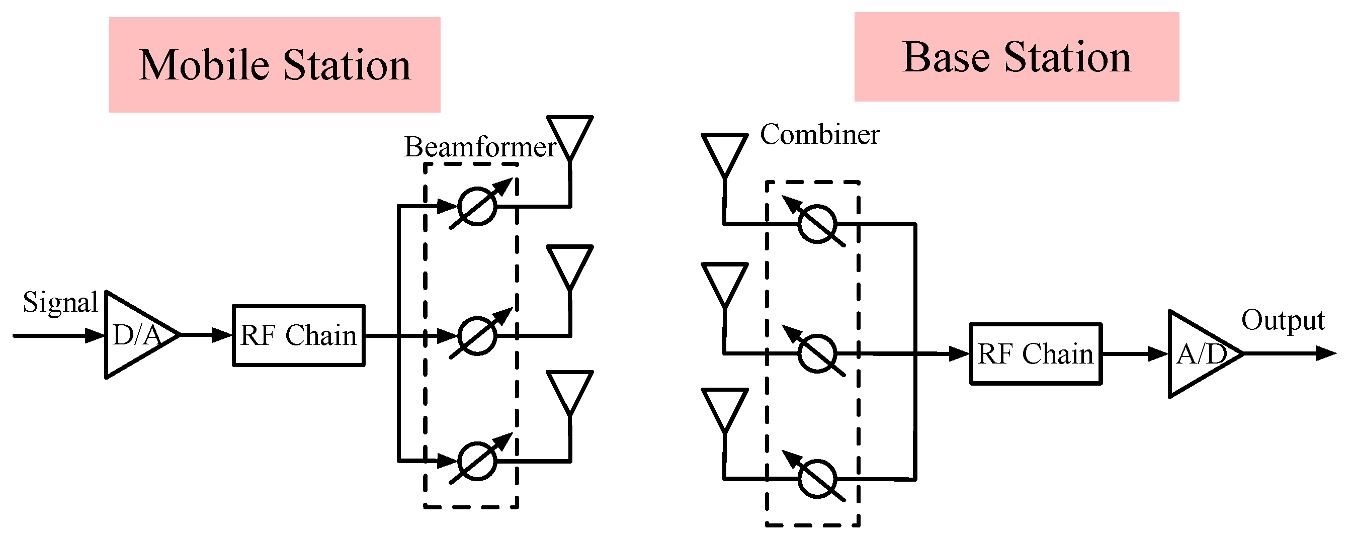
2. System Model of mmWave Communcation

2.1. System Model with MC Effect

As shown in Figure 1, the mmWave MIMO communication system has M antennas in the base station (BS) and N antennas in the mobile station (MS). The transmitting and receiving antennas have the same polarization (horizontal polarization or vertical polarization). Additionally, we solve the problem of 1-D problem and not 2-D problem in both TX and RX sides. In this paper, we only use the analog beamforming in BS and MS, and can extend to the hybrid beamforming structure easily.
The beamfroming vector used in the transmitter (BS) is a ( t ) C M × 1 , and the beamforming vector used in the received (MS) is b ( t ) C N × 1 , so in the time instant t, the received signal can be expressed as
r ( t ) = [ C R b ( t ) ] H H [ C T a ( t ) ] s ( t ) + n ( t ) ,
where s ( t ) denotes the tramitted symbol, H C N × M denotes the mmWave channel matrix, and n ( t ) denotes the additive white Gaussian noise (AWGN). The MC matrices in the transmitter and received are denoted as C T and C R , respectively.
Usually, the MC matrices in the transmitter and receiver are, respectively, described by [19]
C T Z TA + Z TL Z T + Z TL I 1 ,
C R Z RA + Z RL Z R + Z RL I 1 ,
where Z TL and Z TA denote the terminating load and the antenna impedance in transmitter, and Z RL and Z RA denote the terminating load and the antenna impedance in receiver. Z R and Z T denote the mutual impedance matrix in receiver and transmitter, respectively.
The m 1 -th row and m 2 -th column of mutual impedance matrix Z T can be expressed as [20,21,22]
Z T , m 1 , m 2 = 30 ( 0.5772 + ln ( 2 γ L ) g C ( 2 γ L ) + j g S ( 2 γ L ) ) , m 1 = m 2 30 ( g R ( m 1 , m 2 ) + j g X ( m 1 , m 2 ) ) , m 1 m 2
where γ 2 π / λ , and L denotes the length of dipole antennas. g R ( m 1 , m 2 ) and g X ( m 1 , m 2 ) are defined respectively as
g R ( m 1 , m 2 ) sin ( γ L ) [ g S ( ν 0 ) g S ( μ 0 ) + 2 g S ( μ 1 )   2 g S ( ν 1 ) ] + cos ( γ L ) [ g C ( μ 0 ) + g C ( ν 0 ) 2 g C ( μ 1 )   2 g C ( ν 1 ) + 2 g C ( γ d ( m 1 , m 2 ) ) ] [ 2 g C ( μ 1 ) + 2 g C ( ν 1 )   4 g C ( γ d ( m 1 , m 2 ) ) ] ,
g X ( m 1 , m 2 ) sin ( γ L ) [ g C ( ν 0 ) g C ( μ 0 ) + 2 g C ( μ 1 )   2 g C ( ν 1 ) ] + cos ( γ L ) [ g S ( μ 0 ) g S ( ν 0 ) + 2 g S ( μ 1 )   + 2 g S ( ν 1 ) 2 g S ( γ d ( m 1 , m 2 ) ) ] + [ 2 g S ( μ 1 ) + 2 g S ( ν 1 )   4 g S ( γ d ( m 1 , m 2 ) ) ] ,
where d ( m 1 , m 2 ) denotes the distance between the m 1 -th antenna and the m 2 -th antenna. μ 0 , ν 0 , μ 1 and ν 1 are defined, respectively, as
μ 0 = γ d 2 ( m 1 , m 2 ) + L 2 L ,
ν 0 = γ d 2 ( m 1 , m 2 ) + L 2 + L ,
μ 1 = γ d 2 ( m 1 , m 2 ) + 0.25 L 2 0.5 L ,
ν 1 = γ d 2 ( m 1 , m 2 ) + 0.25 L 2 + 0.5 L .
g C ( x ) and g S ( x ) are defined respectively as
g C ( x ) x cos ( t ) t d t ,
g S ( x ) 0 x sin ( t ) t d t .
Similarly, the mutual impedance matrix Z R can be also obtained from the expression of Z T .
However, the expresses for Z T and Z R in (4) are too complex to analysis. Since Z T and Z R depend on the length of dipole antennas and the distances between antennas, the MC matrices C T and C R can be approximated, respectively, by two symmetric Toeplitz matrices [23,24,25].
C T T ( c T ) ,
C R T ( c R ) ,
where T ( c T ) C M × M is defined as
T ( c T ) c T , 0 c T , 1 c T , 2 c T , M 1 c T , 1 c T , 0 c T , 1 c T , M 2 c T , 2 c T , 1 c T , 0 c T , M 3 c T , M 1 c T , M 2 c T , M 3 c T , 0 ,
and T ( c R ) C N × N is defined similarly. Additionally, for the MC matrices, we also have
1 = | c T , 0 | | c T , 1 | | c T , M 1 | ,
1 = | c R , 0 | | c R , 1 | | c R , N 1 | .
Therefore, in the scenario with MC between antennas, the received signal in (1) can be rewritten as
r ( t ) = b H T H ( c R ) H T ( c T ) a s ( t ) + n ( t ) .
Usually, the mmWave channel can be described by a geometric channel model
H = k = 0 K 1 a k c ( ϕ k ) d H ( ψ k ) ,
where K denotes the number of paths, a k denotes the complex gain of the k-th path, ϕ k and ψ k are the DoD and DoA, respectively. We define the following vectors to collect DoD/DoA
ϕ ϕ 0 , ϕ 1 , , ϕ K 1 T ,
ψ ψ 0 , ψ 1 , , ψ K 1 T .
c ( ϕ k ) and d H ( ψ k ) are the steering vectors of receiver and transmitter, and can be expressed as
c ( ϕ k ) = 1 N 1 , e j 2 π d λ sin ( ϕ k ) , , e j 2 π ( N 1 ) d λ sin ( ϕ k ) T
d ( ψ k ) = 1 M 1 , e j 2 π d λ sin ( ψ k ) , , e j 2 π ( M 1 ) d λ sin ( ψ k ) T ,
where d denotes the distance between adjacent antennas, and λ denotes the wavelength.
We define the following matrices
C c ( ϕ 0 ) , c ( ϕ 1 ) , , c ( ϕ K 1 )
D d ( ψ 0 ) , d ( ψ 1 ) , , d ( ψ K 1 ) ,
and the channel model can be rewritten as
H = C G D H ,
where G C K × K is a diagonal matrix and G diag { a 0 , a 1 , , a K 1 } . Substituting (26) into (18), we can obtain
r ( t ) = b H ( t ) T H ( c R ) C G D H T ( c T ) a ( t ) s ( t ) + n ( t )   = ( D H T ( c T ) a ( t ) ) T ( b H ( t ) T H ( c R ) C ) g s ( t ) + n ( t )   = a T ( t ) b H ( t ) T T ( c T ) D T H ( c R ) C g s ( t ) + n ( t ) ,
where the vector g vec { G } .
With the sampling interval T s , we can collect the P sampled signals into a vector
r r ( 0 ) , r ( T s ) , , r ( ( P 1 ) T s ) T .
Then, with s ( t ) = 1 , we can obtain
r = a T ( 0 ) b H ( 0 ) a T ( T s ) b H ( T s ) a T ( ( P 1 ) T s ) b H ( ( P 1 ) T s ) Ψ T T ( c T ) D T H ( c R ) C g + n   = Ψ T T ( c T ) T H ( c R ) ( D C ) g + n
where n n ( 0 ) , n ( T s ) , , n ( ( P 1 ) T s ) T .

2.2. Sparse-Based mmWave Channel Model

To estimate the mmWave channel H , we can discretize the DoD and DoA into grids, and the channel model in (26) can be rewritten as
H = EUF H ,
where we have
E c ( ζ 0 ) , c ( ζ 1 ) , , c ( ζ N r 1 )
F d ( ξ 0 ) , d ( ξ 1 ) , , d ( ξ N t 1 ) .
N r and N t are the numbers of DoD and DoA grids, respectively. ζ n and ξ n are the n-th discretized grids of DoD and DoA, respectively. U is a sparse matrix, and entry at the n 1 -th row and n 2 -th column of U is
U n 1 , n 2 = a k , ζ n 1 = ϕ k and ξ n 2 = ψ k 0 , otherwise .
Therefore, the received signal in (29) can be rewritten in a sparse model as
r = Ψ T T ( c T ) T H ( c R ) ( F E ) u + n ,
where u vec { U } is a sparse vector. As shown in (34), the sparse model is different from the conventional compressed sensing model, where the additional matrix T T ( c T ) T H ( c R ) is introduced to describe the unknown MC effect between antennas.

3. Sparse-Based Channel Estimation With Unknown MC Effect

With the sparse model (34), we propose a two-stage method to estimate the mmWave Channel with the unknown MC between antennas. In the two-stage method, the sparse vector can be estimated firstly, and then the MC matrix T T ( c T ) T H ( c R ) is estimated with the estimated u ^ . In the sparse reconstruction processes, the orthogonal matching pursuit (OMP) method [26,27] can be adopted.
To estimate the MC vectors c T and c R , we can rewrite the system model in (34) as
r = Ψ Q F Q E I N t c T I N r c R u ϑ + n
where we define
Q F Q F ( ξ 0 ) , Q F ( ξ 1 ) , , Q F ( ξ N t 1 ) ,
Q E Q E ( ζ 0 ) , Q E ( ζ 1 ) , , Q E ( ζ N r 1 ) .
Q F ( ξ n ) is a matrix and the entries are from the vector d ( ξ n ) , and Q E ( ζ n ) is a matrix and the entries are from the vector c ( ζ n ) . Both Q F ( ξ n ) and Q E ( ζ n ) can be obtained from the following lemma.
Lemma 1.
For complex symmetric Toeplitz matrix A = Toeplitz a C M × M and complex vector c C M × 1 , we have [28,29]
Ac = Qa ,
where a is a vector formed by the first row of A , and Q = Q 1 + Q 2 with the p-th ( p = 0 , 1 , , M 1 ) row and q-th ( q = 0 , 1 , , M 1 ) column entries being
[ Q 1 ] p , q = c p + q , p + q M 1 0 , otherwise ,
[ Q 2 ] p , q = c p q , p q 1 0 , otherwise .
We can obtain the following equations
ϑ = I N t c T I N r c R u   = vec I N c R u T I N t c T T I N r   = I N t c T I N r u I N c R   = vec c R u T I N t c T T I N r I M N t N r   = ( I M N t N r c R ) I N t c T I N r u   = ( I M N t N r c R ) vec I M N r ( c T I N r ) U   = ( I M N t N r c R ) ( U T I M N r ) vec c T I N r   = ( I M N t N r c R ) vec c T U   = vec { c R vec T c T U }
= vec c T U I N c R .
Therefore, with (41), the system model in (35) can be rewritten as
r = Ψ Q F Q E ( I M N t N r c R ) ( U T I M N r ) Ξ T vec c T I N r + n ,
and with (42), the system model in (35) can be rewritten as
r = Ψ Q F Q E ( vec c T U I N ) Ξ R c R + n ,
We will use (43) and (44) to estimate the MC vectors cT and cR, respectively.
The steepest descent-based method is proposed to estimate the MC vectors. For cT, we define the following objective function from (43)
f T ( c T ) r Ξ T vec c T I N r 2 2 .
Then, we can obtain
f T ( c T ) c T = r H Ξ T vec c T I N r c T vec H c T I N r Ξ T H r c T   + vec H c T I N r Ξ T H Ξ T vec c T I N r c T = r H Ξ T vec c T I N r c T ( Ξ T H r ) T vec c T I N r c T   + ( Ξ T H Ξ T vec c T I N r ) T vec c T I N r c T   + vec H c T I N r Ξ T H Ξ T vec c T I N r c T = ( Ξ T H Ξ T vec c T I N r Ξ T H r ) T vec c T I N r c T = ( Ξ T vec c T I N r r ) T Ξ T Ω T ,
where Ω T ω T , 0 , ω T , 1 , , ω T , M 1 , and the m-th column of ΩT is defined as
ω T , m vec e m M I N r ,
and e m M is a M × 1 vector with the m-th entry being 1 and other entries being 0.
Similarly, we defined the following objective function to estimate c R from (44)
f R ( c R ) r Ξ R c R 2 2 .
Then, we can obtain
f R ( c R ) c R = r H Ξ R c R c R c R T Ξ R H r c R + c R T Ξ R H Ξ R c R c R v   = c R T Ξ R H r H Ξ R .
In Algorithm 1, the details about the proposed method to estimate the mmWave channel is given with the unknown MC effect. In Algorithm 1, the computational complexity of the sparse reconstruction can be obtained as O ( K N t N r P ) + O ( K 4 ) + O ( K 3 P ) . The computational complexity of steepest descent is O ( P M N r ) + O ( P N N t ) + O ( P 2 N t ) . Therefore, with K N t , the computational complexity can be finally obtained as O ( K N t N r P ) .
Algorithm 1 Channel estimation with MC effect
1:
Input: received signal r , the matrices Ψ , Q F and E , the maximum of iteration N iter , the step δ .
2:
Initialization: t = 0 , c ^ T T = [ 1 , 0 1 × ( M 1 ) ] T , c ^ R T = [ 1 , 0 1 × ( N 1 ) ] T , u ^ = 0 N T N R × 1 .
3:
while t N iter do
4:
t t + 1 .
5:
 Obtain MC matrices T ( c ^ T ) and T ( c ^ R ) .
6:
 Obtain Λ Ψ T T ( c T ) T H ( c R ) ( F E ) , and Λ λ 0 , λ 1 , , λ N T N R 1 is the column-normalized matrix of Λ .
7:
k = 1 , z = r , ρ = .
8:
while k K do
9:
   n max = arg max n z λ n .
10:
   ρ ρ n max .
11:
   z = r Λ ρ Λ ρ r , where Λ ρ is a matrix with the | ρ | columns from Λ and † is the Moore-Penrose inverse.
12:
end while
13:
u ^ ρ = Λ ρ r with other entries of u ^ being 0.
14:
 Obtain ν T t = f T ( c T ) c T c T = c ^ T t 1 from (46).
15:
 Obtain ν R t = f R ( c R ) c R c R = c ^ R t 1 from (49).
16:
ν = ν T t T , ν R t T .
17:
c ^ T t , T , c ^ R t , T c ^ T t 1 , T c ^ R t 1 , T δ ν t , T .
18:
end while
19:
Output: the sparse vector u ^ .

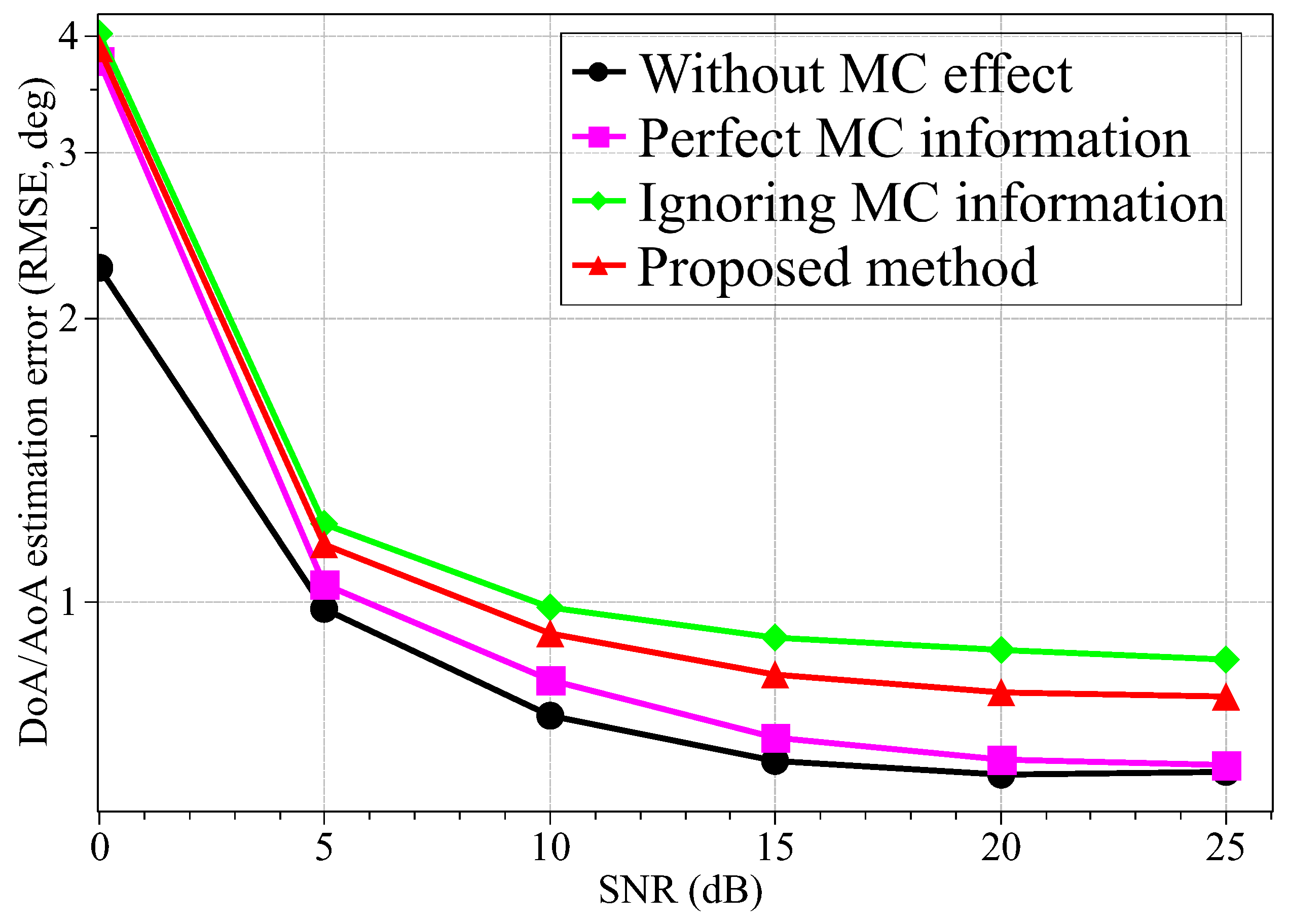
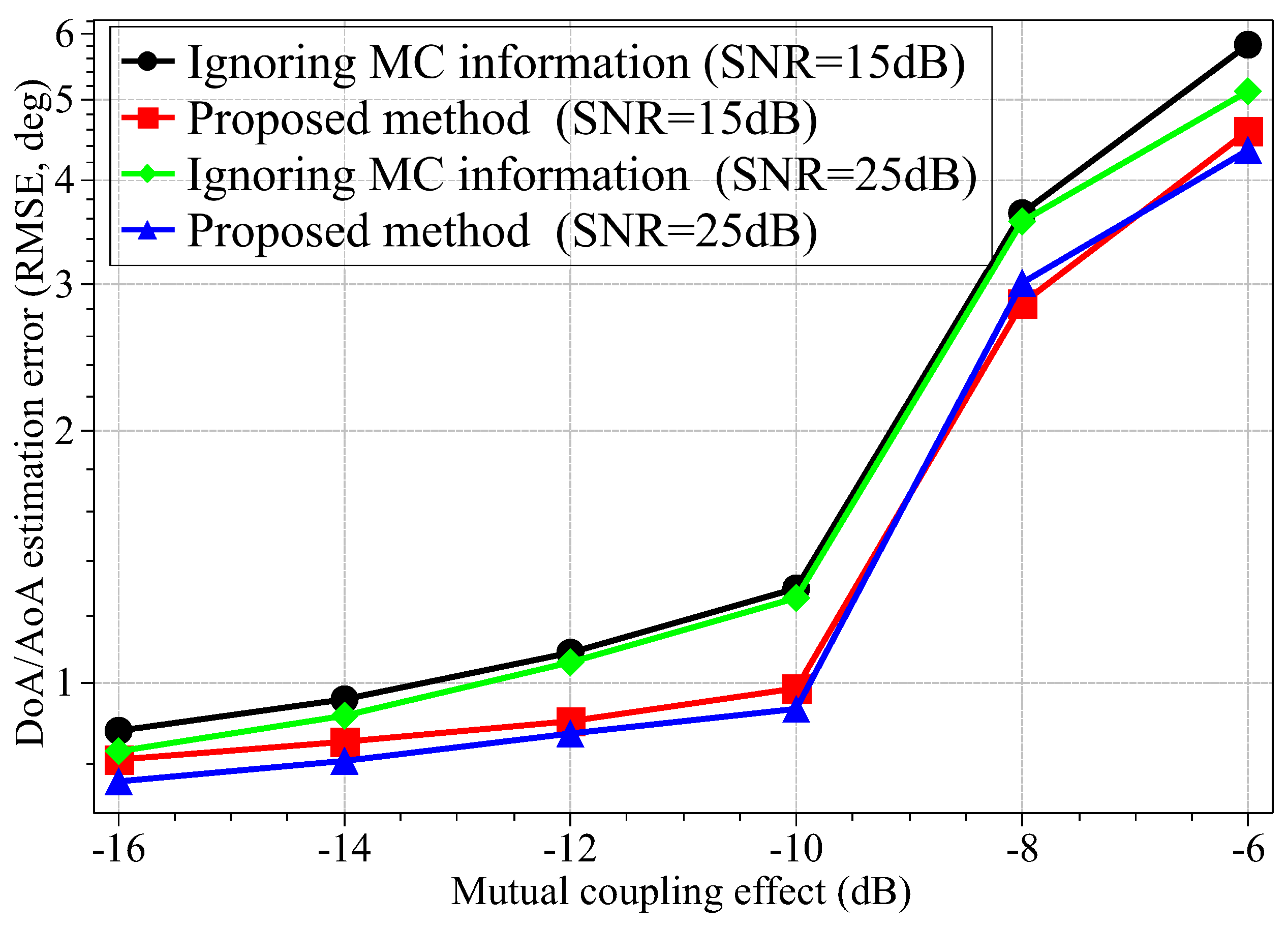
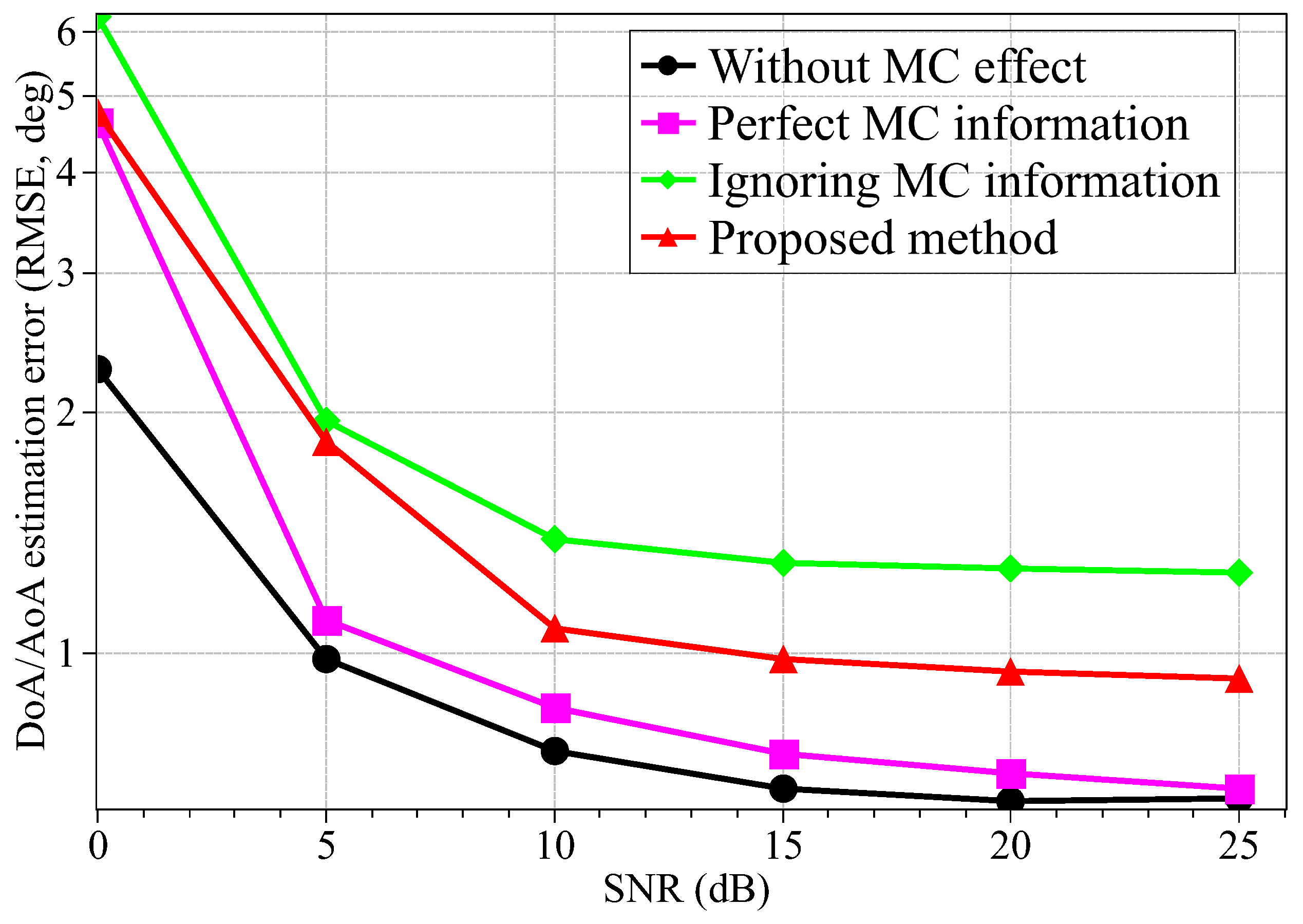
4. Simulation Results

In this section, the simulation results are given, and the simulation parameters are given in Table 1, where the grids in Table 1 are for the 1-D arrangement. MATLAB codes have been made available online at https://drive.google.com/drive/folders/1dFw-XktTZaPQeCZnQMr6Gr_igRBdH0Rk?usp=sharing. All experiments are carried out in Matlab R2017b on a PC with a 2.9 GHz Intel Core i5 and 8 GB of RAM. The beamforming vectors a ( t ) and b ( t ) are uniformly chosen from a unit circle, and this scheme is referred to as a random coding scheme. The DoD/DoA estimation performance is measured by root-mean-square error (RMSE)
e = 1 2 K N p n = 0 N p 1 ϕ ^ ϕ 2 2 + ψ ^ ψ 2 2 ( deg ) ,
where ϕ ^ and ϕ ^ denote the estimated DoA and DoD, respectively. N p denotes the number of pairs to simulate DoD/DoA. The DoD and DoA are randomly chosen from [−45°, 45°] and the minimum space of DoD/DoA for different path is greater than 10°. The signal-to-noise (SNR) ratio is defined as
SNR y H y E { n H n }
where y denotes the signal y Ψ T T ( c T ) T H ( c R ) ( D C ) g , and n denotes the additive white Gaussian noise (AWGN), and the entries of n follow the zero-mean complex Gaussian distribution n CN ( 0 , σ n 2 I ) .
First, the DoD/DoA estimation performance with different SNRs is given in Figure 2, where the MC effect between adjacent antennas is 15 dB. The curve “Without MC effect” is the DoD/DoA estimation performance of OMP method in the scenario without the MC effect. The curve “Perfect MC information” denotes the DoD/DoA estimation performance of the proposed method with perfect MC information, so the MC vectors are not updated in the proposed method. The curve “Ignoring MC information” denotes the DoD/DoA estimation performance of traditional OMP method without considering the MC effect. The curve “Proposed method” denotes the DoD/DoA estimation performance using the proposed method. As shown in this figure, the DoD/DoA estimation performance can be significantly improved by the proposed method with the additional estimation for MC effect. When SNR is 20 dB, the RMSE of the traditional OMP method is 0.889°, but the RMSE can be decreased to 0.800° (10% improvement). The same estimation performance can be achieved by the proposed method when SNR is 12 dB, so the estimation performance is improved by 8 dB.
Then, with the MC effect being −10 dB, we show the DoD/DoA estimation performance in Figure 3. When SNR is 20 dB, the RMSE of the traditional OMP method is 1.276°, and that of the proposed method is 0.948° (25.7% improvement). Therefore, with worse MC effect, the DoD/DoA estimation performance is improved more efficiently using the proposed method.
Figure 4 shows the DoD/DoA estimation performance with different MC effect. When the MC effect is greater than 10 dB, the estimation performance will be worse significantly. When the MC effect is less than 10 dB, the MC effect can be reduced by about 4 dB using the proposed method. Therefore, the proposed method is efficient for the mmWave channel estimation in the scenario with the MC effect.

5. Conclusions

In this paper, the channel estimation problem in the mmWave communication system has been investigated. The unknown MC effect is described by a symmetric Toeplitz matrix, and the sparse-based mmWave system model with MC coefficients has been formulated. Then, by exploiting the channel sparsity in the spatial domain, the two-stage method based CS has been proposed by estimating the DoD/DoA and MC coefficients iteratively. Simulation results show that the proposed method can improve the estimation performance of mmWave channel significantly. Future work will focus on mmWave channel estimation with moving users.

Author Contributions

Conceptualization, Z.C. (Zhenxin Cao) and H.G.; Methodology, Z.C. (Zhenxin Cao) and H.G.; software, Z.C. (Zhimin Chen); validation, Z.C. (Zhenxin Cao); formal analysis, Z.C. (Zhimin Chen); investigation, P.C.; resources, H.G.; data curation, Z.C. (Zhenxin Cao); writing—original draft preparation, H.G.; writing—Review and editing, Z.C. (Zhimin Chen); visualization, P.C.; supervision, P.C.; project administration, Z.C. (Zhimin Chen); funding acquisition, P.C.

Funding

This work was supported in part by the National Natural Science Foundation of China (Grant No. 61471117, 61801112, 61601281), the Natural Science Foundation of Jiangsu Province (Grant No. BK20180357), the Open Program of State Key Laboratory of Millimeter Waves at Southeast University (Grant No. Z201804), and Nanjing Overseas Science and Technology Project (Grant No. 1104000384).

Conflicts of Interest

The authors declare no conflict of interest.

References

  1. Rangan, S.; Rappaport, T.S.; Erkip, E. Millimeter-wave cellular wireless networks: Potentials and challenges. Proc. IEEE 2014, 102, 366–385. [Google Scholar] [CrossRef]
  2. Ghosh, A.; Thomas, T.A.; Cudak, M.C.; Ratasuk, R.; Moorut, P.; Vook, F.W.; Rappaport, T.S.; MacCartney, G.R.; Sun, S.; Nie, S. Millimeter-wave enhanced local area systems: A high-data-rate approach for future wireless networks. IEEE J. Sel. Areas Commun. 2014, 32, 1152–1163. [Google Scholar] [CrossRef]
  3. Cao, Z.; Chen, P.; Chen, Z.; He, X. Maximum Likelihood-Based Methods for Target Velocity Estimation with Distributed MIMO Radar. Electronics 2018, 7, 29. [Google Scholar] [CrossRef]
  4. Swindlehurst, A.L.; Ayanoglu, E.; Heydari, P.; Capolino, F. Millimeter-wave massive MIMO: The next wireless revolution? IEEE Commun. Mag. 2014, 52, 56–62. [Google Scholar] [CrossRef]
  5. Alkhateeb, A.; Ayach, O.E.; Leus, G.; Heath, R.W. Channel estimation and hybrid precoding for millimeter wave cellular systems. IEEE J. Sel. Top. Signal Process. 2014, 8, 831–846. [Google Scholar] [CrossRef]
  6. Chen, P.; Zheng, L.; Wang, X.; Li, H.; Wu, L. Moving target detection using colocated MIMO radar on multiple distributed moving platforms. IEEE Trans. Signal Process. 2017, 65, 4670–4683. [Google Scholar] [CrossRef]
  7. Vlachos, E.; Alexandropoulos, G.C.; Thompson, J. Massive MIMO channel estimation for millimeter wave systems via matrix completion. IEEE Signal Process. Lett. 2018, 25, 1675–1679. [Google Scholar] [CrossRef]
  8. Cao, Z.; Chen, P.; Chen, Z.; Jin, Y. DOA Estimation for Multiple Targets in MIMO Radar with Nonorthogonal Signals. Math. Probl. Eng. 2018, 2018. [Google Scholar] [CrossRef]
  9. Fan, D.; Gao, F.; Liu, Y.; Deng, Y.; Wang, G.; Zhong, Z.; Nallanathan, A. Angle domain channel estimation in hybrid mmWave massive MIMO systems. IEEE Trans. Wirel. Commun. 2018, in press. [Google Scholar] [CrossRef]
  10. La Tosa, V.; Denis, B.; Uguen, B. Direct path DoA and DoD finding through IR-UWB communications. In Proceedings of the 2008 IEEE International Conference on Ultra-Wideband, Hannover, Germany, 10–12 September 2008; Volume 2, pp. 223–227. [Google Scholar]
  11. Li, X.; Fang, J.; Li, H.; Wang, P. Millimeter wave channel estimation via exploiting joint sparse and low-rank structures. IEEE Trans. Wirel. Commun. 2018, 17, 1123–1133. [Google Scholar] [CrossRef]
  12. Lin, X.; Wu, S.; Jiang, C.; Kuang, L.; Yan, J.; Hanzo, L. Estimation of broadband multiuser millimeter wave massive MIMO-OFDM channels by exploiting their sparse structure. IEEE Trans. Wirel. Commun. 2018, 17, 3959–3973. [Google Scholar] [CrossRef]
  13. Zheng, Z.; Zhang, J.; Zhang, J. Joint DOD and DOA estimation of bistatic MIMO radar in the presence of unknown mutual coupling. Signal Process. 2012, 92, 3039–3048. [Google Scholar] [CrossRef]
  14. Clerckx, B.; Craeye, C.; Vanhoenacker-Janvier, D.; Oestges, C. Impact of antenna coupling on 2 × 2 MIMO communications. IEEE Trans. Veh. Technol. 2007, 56, 1009–1018. [Google Scholar] [CrossRef]
  15. Chen, P.; Cao, Z.; Chen, Z.; Wang, X. Off-Grid DOA Estimation Using Sparse Bayesian Learning in MIMO Radar With Unknown Mutual Coupling. IEEE Trans. Signal Process. 2019, 67, 208–220. [Google Scholar] [CrossRef]
  16. Liu, J.; Zhang, Y.; Lu, Y.; Ren, S.; Cao, S. Augmented nested arrays with enhanced DOF and reduced mutual coupling. IEEE Trans. Signal Process. 2017, 65, 5549–5563. [Google Scholar] [CrossRef]
  17. Rocca, P.; Hannan, M.A.; Salucci, M.; Massa, A. Single-snapshot DoA estimation in array antennas with mutual coupling through a multiscaling BCS strategy. IEEE Trans. Antennas Propag. 2017, 65, 3203–3213. [Google Scholar] [CrossRef]
  18. Chen, P.; Cao, Z.; Chen, Z.; Liu, L.; Feng, M. Compressed Sensing-Based DOA Estimation with Unknown Mutual Coupling Effect. Electronics 2018, 7, 424. [Google Scholar] [CrossRef]
  19. Zhang, C.; Huang, H.; Liao, B. Direction finding in MIMO radar with unknown mutual coupling. IEEE Access 2017, 5, 4439–4447. [Google Scholar] [CrossRef]
  20. Lin, M.; Yang, L. Blind calibration and DOA estimation with uniform circular arrays in the presence of mutual coupling. IEEE Antennas Wirel. Propag. Lett. 2006, 5, 315–318. [Google Scholar] [CrossRef]
  21. Liu, C.L.; Vaidyanathan, P.P. Super nested arrays: Linear sparse arrays with reduced mutual coupling—Part I: Fundamentals. IEEE Trans. Signal Process. 2016, 64, 3997–4012. [Google Scholar] [CrossRef]
  22. Liu, L.; Zhang, X.; Chen, P. Compressed sensing-based DOA estimation with antenna phase errors. Electronics 2019, 8, 294. [Google Scholar] [CrossRef]
  23. Liao, B.; Zhang, Z.G.; Chan, S.C. DOA estimation and tracking of ULAs with mutual coupling. IEEE Trans. Aerosp. Electron. Syst. 2012, 48, 891–905. [Google Scholar] [CrossRef]
  24. Basikolo, T.; Ichige, K.; Arai, H. A novel mutual coupling compensation method for underdetermined direction of arrival estimation in nested sparse circular arrays. IEEE Trans. Antennas Propag. 2018, 66, 909–917. [Google Scholar] [CrossRef]
  25. Chen, P.; Qi, C.; Wu, L.; Wang, X. Waveform design for Kalman filter-based target scattering coefficient estimation in adaptive radar system. IEEE Trans. Veh. Technol. 2018, 67, 11805–11817. [Google Scholar] [CrossRef]
  26. Chen, P.; Qi, C.; Wu, L.; Wang, X. Estimation of extended targets based on compressed sensing in cognitive radar system. IEEE Trans. Veh. Technol. 2017, 66, 941–951. [Google Scholar] [CrossRef]
  27. Tropp, J.A.; Gilbert, A.C. Signal recovery from random measurements via orthogonal matching pursuit. IEEE Trans. Inf. Theory 2007, 53, 4655–4666. [Google Scholar] [CrossRef]
  28. Termos, A.; Hochwald, B.M. Capacity benefits of antenna coupling. In Proceedings of the 2016 Information Theory and Applications (ITA), La Jolla, CA, USA, 31 January–5 February 2016; pp. 1–5. [Google Scholar]
  29. Liu, X.; Liao, G. Direction finding and mutual coupling estimation for bistatic MIMO radar. Signal Process. 2012, 92, 517–522. [Google Scholar] [CrossRef]
Figure 1. The system model with analog transmit beamforming and receive combining struct.
Electronics 08 00358 g001
Figure 2. The DoD/DoA estimation performance with different SNRs (the MC effect is 15 dB between adjacent antennas).
Electronics 08 00358 g002
Figure 3. The DoD/DoA estimation performance with different SNRs (the MC effect is 10 dB between adjacent antennas).
Electronics 08 00358 g003
Figure 4. The DoD/DoA estimation performance with different MC effect.
Electronics 08 00358 g004
Table 1. Simulation Parameters.
ParameterValue
The number of sampled signals P50
The number of transmitting antennas M20
The number of receiving antennas N10
The number of paths K3
The space between antennas d0.5 wavelength
The grid space δ 0.2°
The detection DoA range[−45°, 45°]

