Coherent Integration for Radar High-Speed Maneuvering Target Based on Frequency-Domain Second-Order Phase Difference


Abstract
:1. Introduction
- (a)
- Radon transform-based algorithms, such as generalized Radon Fourier transform (GRFT) [21], Radon-fractional Fourier transform (RFRFT) [22], and Radon-Lv’s Distribution (RLVD) [23,24,25,26]. These kinds of algorithms implement phase compensation and parameter estimation by searching the maneuvering target motion trajectory. Although they can obtain coherent integration under a low signal-to-noise ratio (SNR), the huge computational load seriously limits their practical application.
- (b)
- KT based algorithms, such as second-order keystone transform (SoKT) [27], Doppler keystone transform (DKT) [28], keystone-Lv’s distribution (KT-LVD) [29], and so on. The KT is used to correct the QRM blindly, which reduces the calculation cost to a certain extent, but it still needs to use parameter searching to eliminate the Doppler ambiguity.
- (c)
- Correlation-based algorithms: The representative adjacent cross-correlation function and Lv’s distribution (ACCF-LVD) algorithm proposed in References [30,31,32] reduces the migration order by ACCF and quickly estimates the motion parameters without any searching procedure, which greatly reduces the computational burden and benefits practical applications. Unfortunately, this method is only effective when the input SNR is high [33]. The three-dimensional scaled transform (TDST) method was then presented to realize coherent integration and motion parameters estimations for maneuvering targets under a low SNR background [34]. This method eliminates the coupling effectively among spatial frequency, slow time, and time delay. However, the complex three-dimensional transform is usually less suitable for realistic applications.
2. Signal Model and Problem Formulation
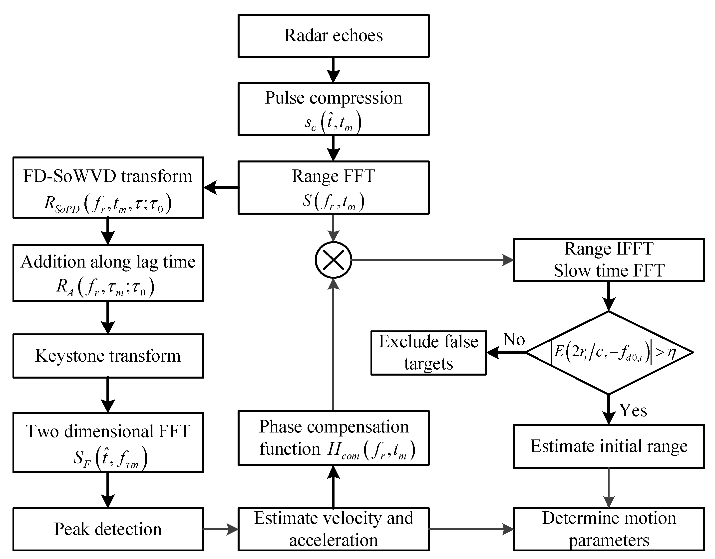
3. The Principle of the FD-SoPD
3.1. FD-SoPD with Mono-Target
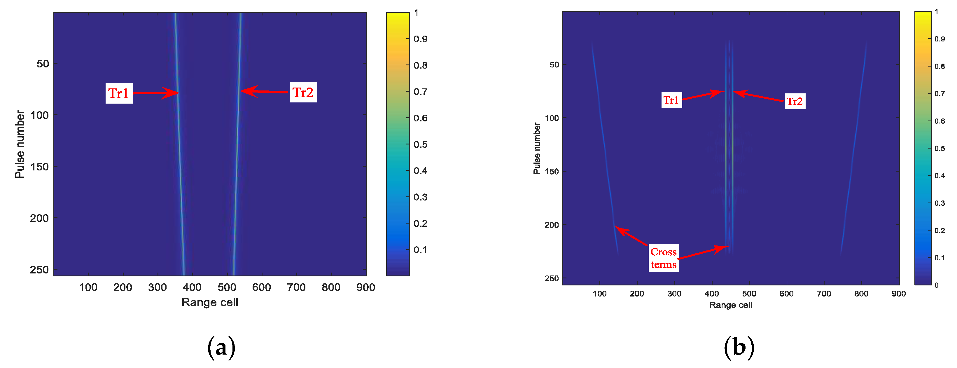
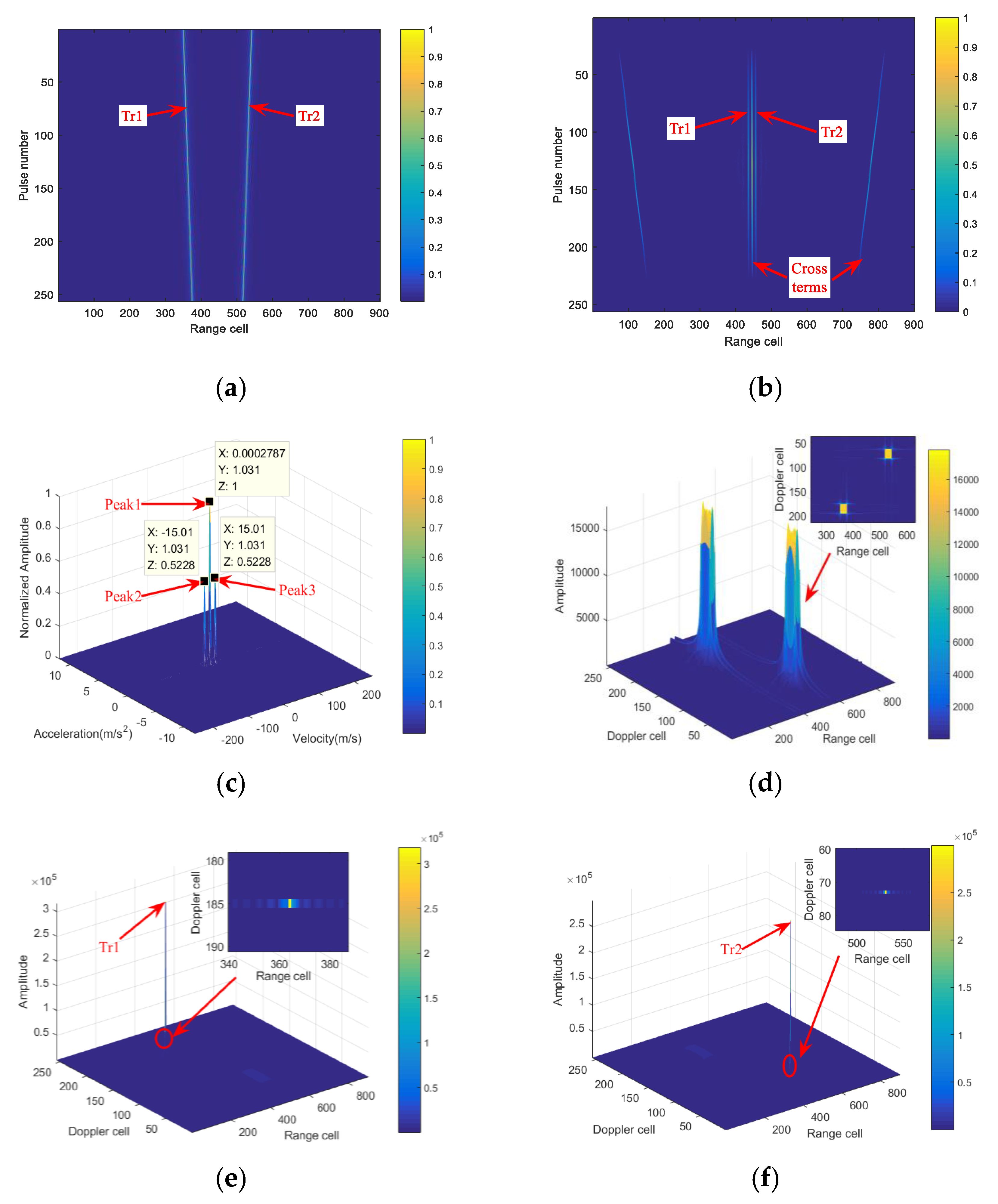
3.2. FD-SoPD with Multi-Targets
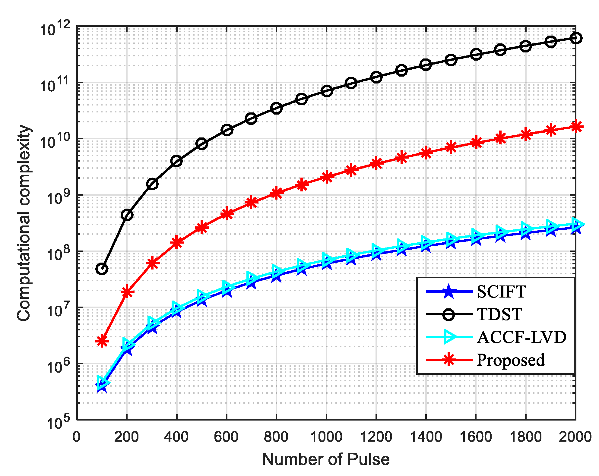
4. Computational Burden Analysis of the FD-SoPD Algorithm
5. Numerical Results
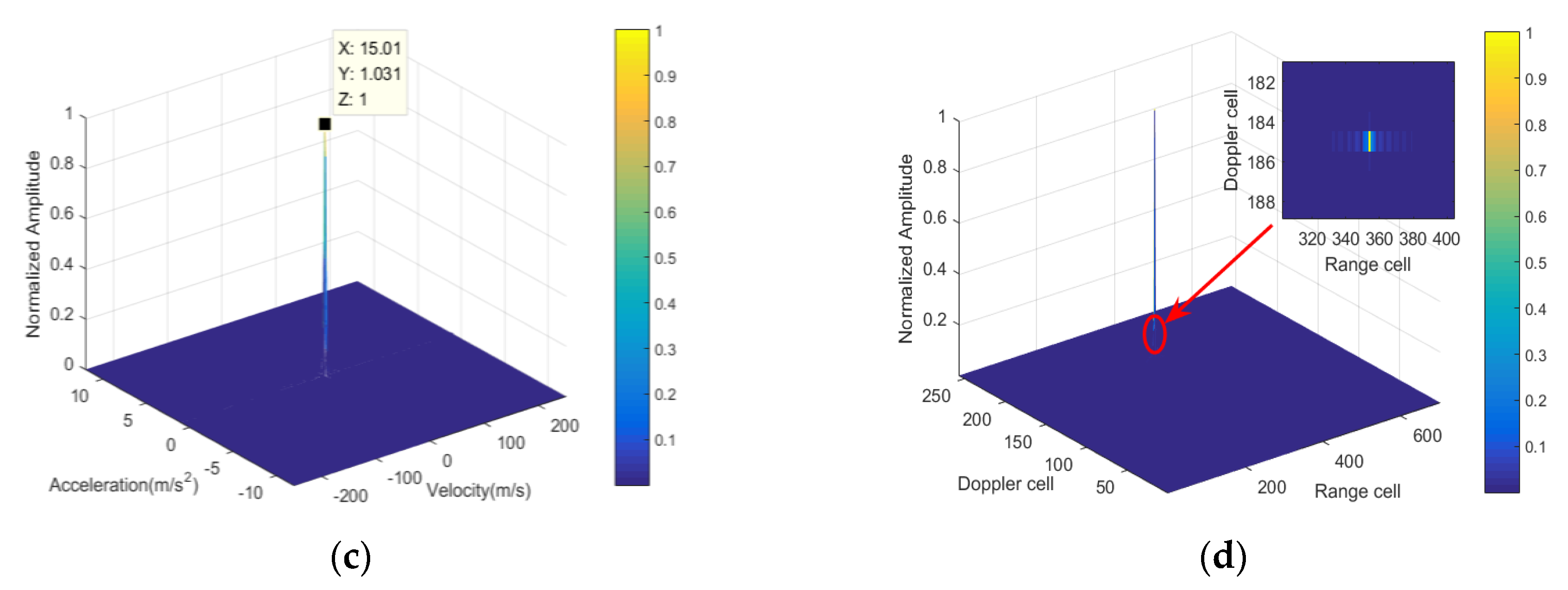
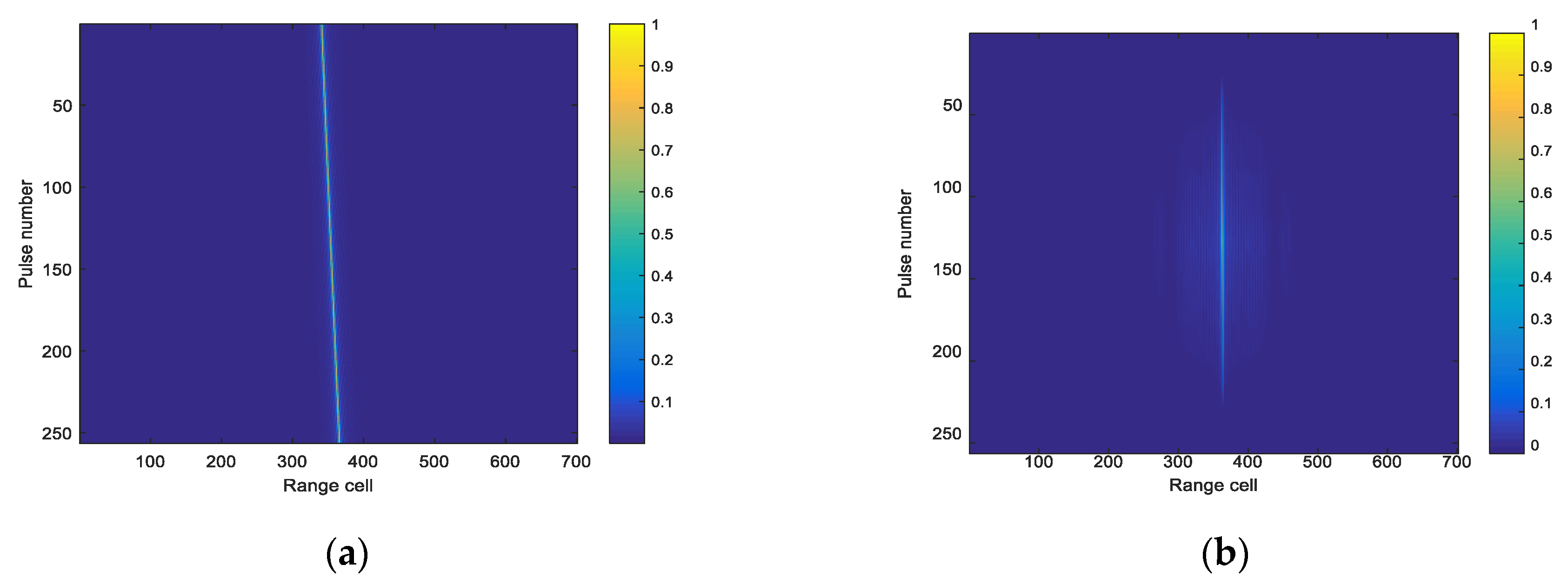
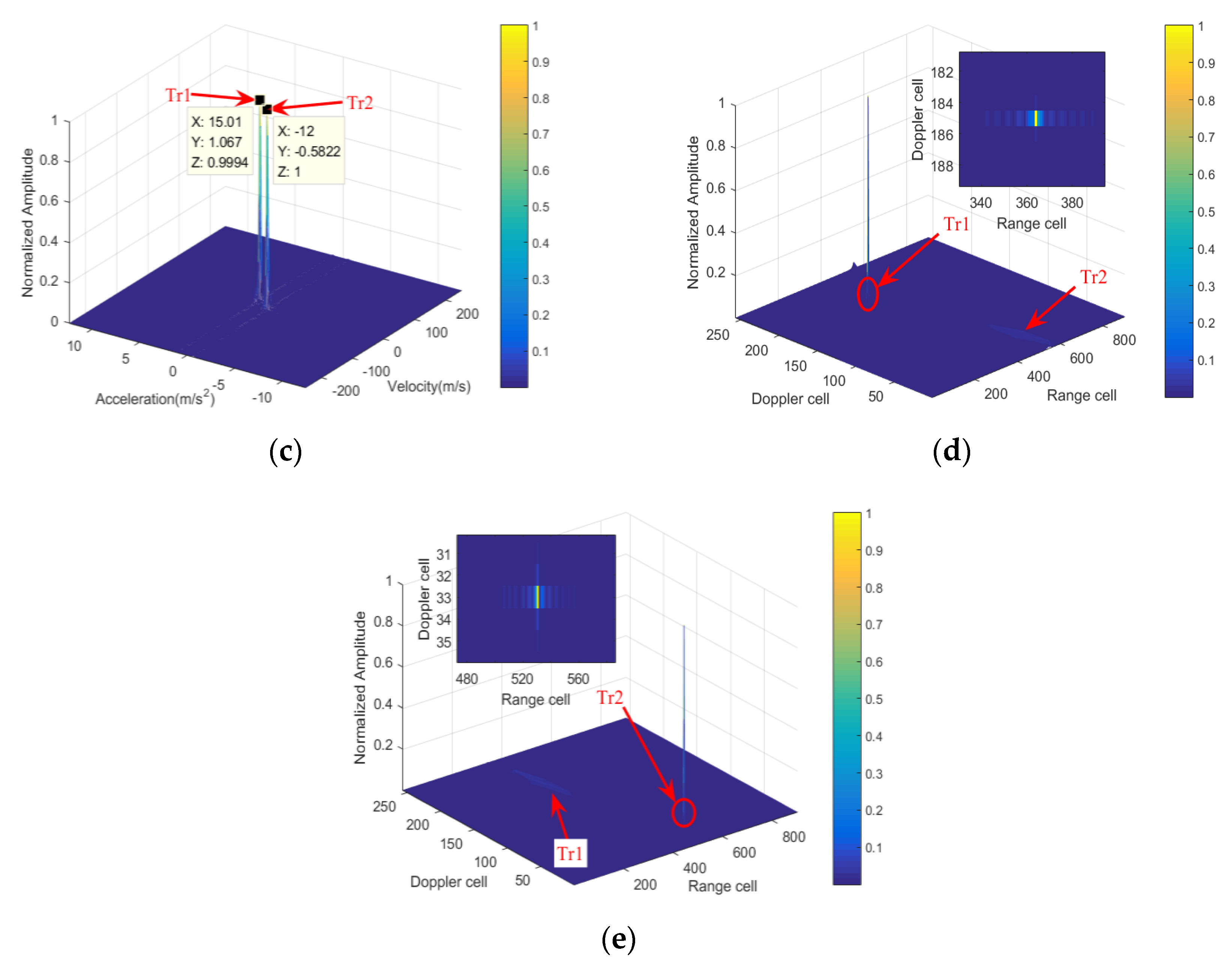
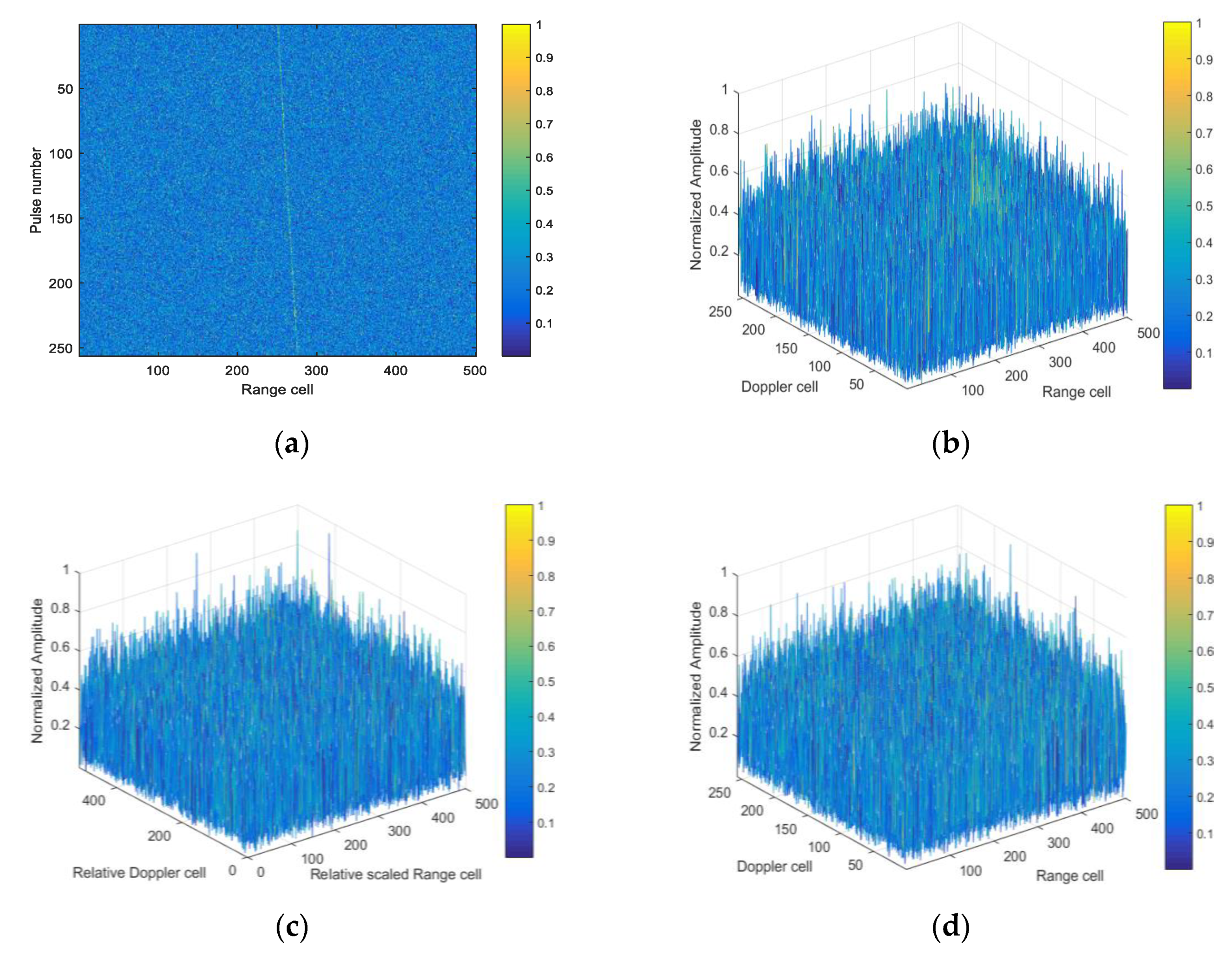
5.1. Coherent Integration Performance
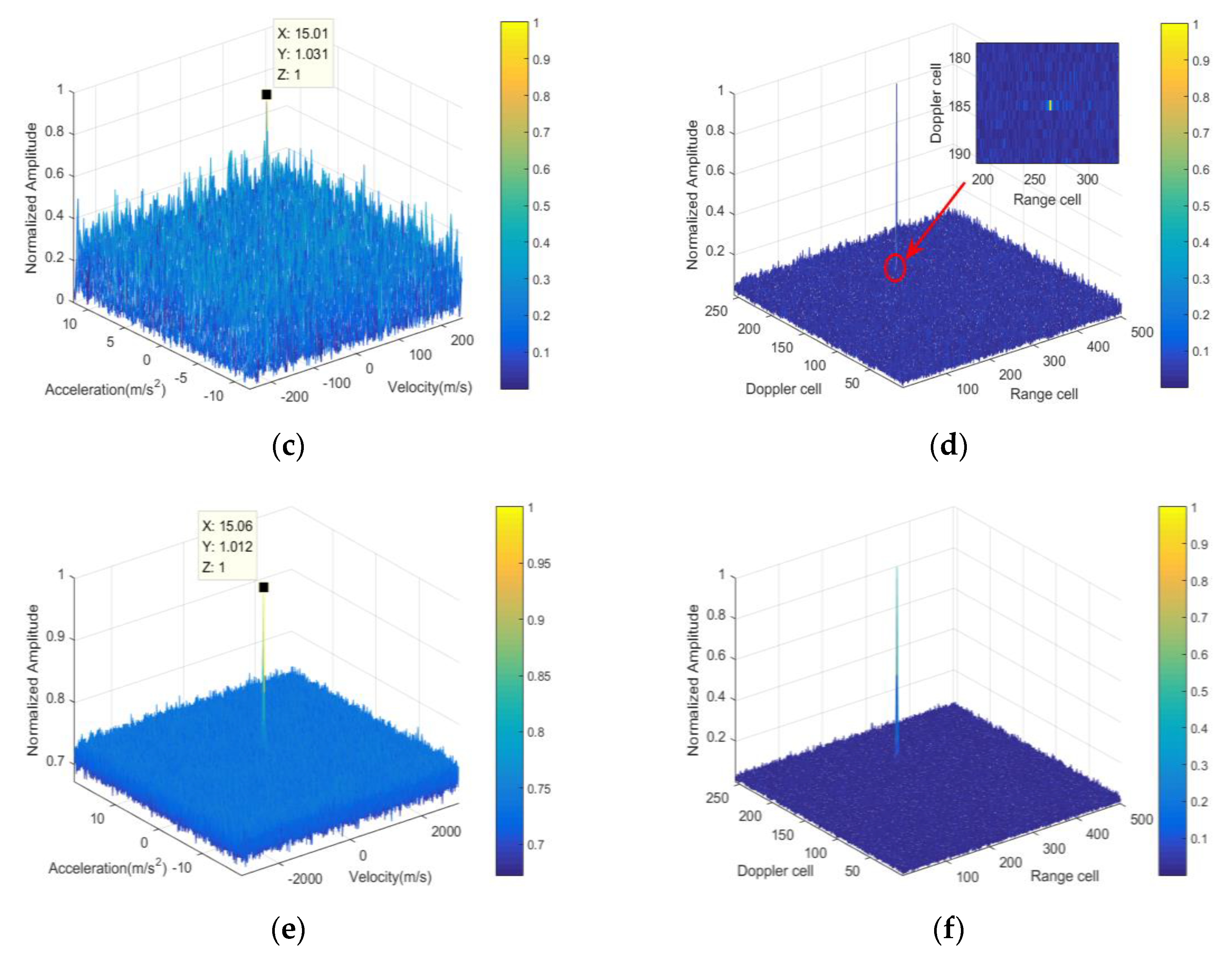
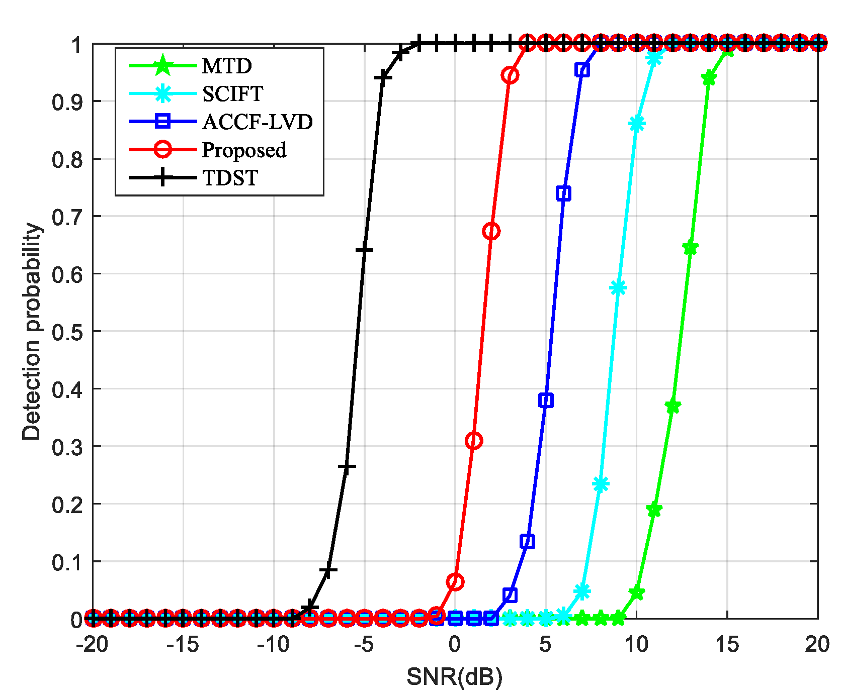
5.2. Detection Performance
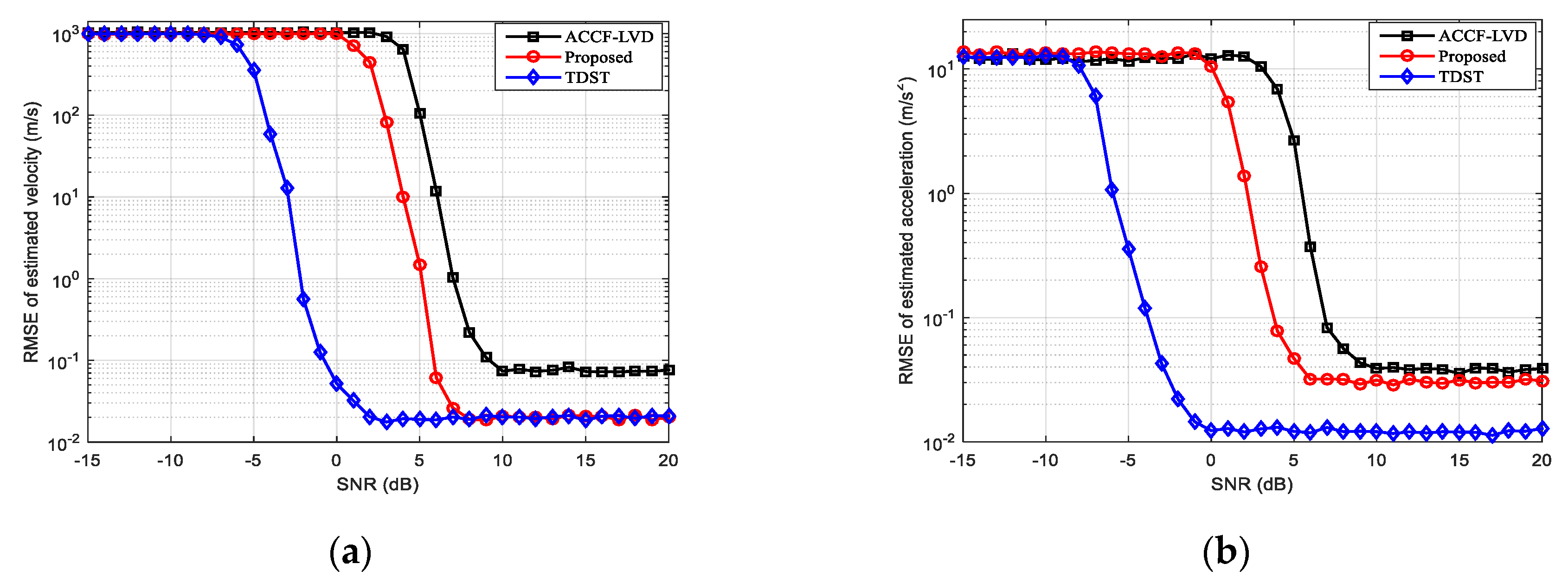
5.3. Parameter Estimation Performance
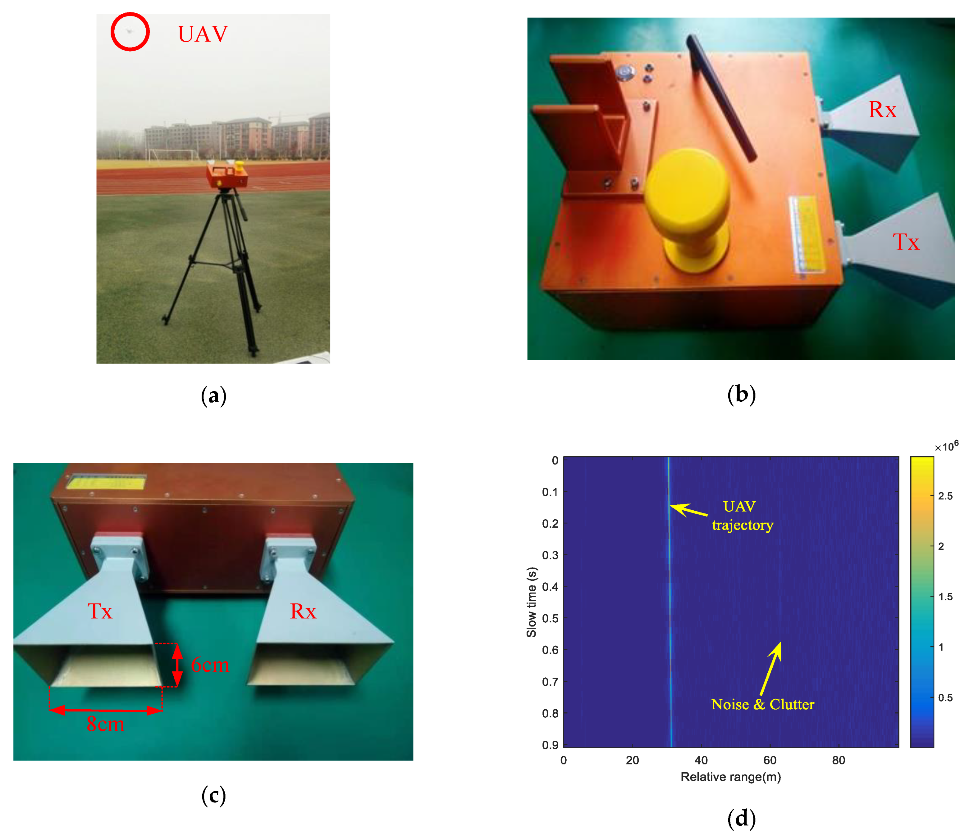
5.4. Experimental Data Processing
6. Conclusions
Author Contributions
Funding
Acknowledgments
Conflicts of Interest
Appendix A
References
- Huang, P.H.; Liao, G.S.; Yang, Z.Z.; Xia, X.G.; Ma, J.T.; Ma, J.T. Long-Time Coherent Integration for Weak Maneuvering Target Detection and High-Order Motion Parameter Estimation Based on Keystone Transform. IEEE Trans. Signal Process. 2016, 64, 4013–4026. [Google Scholar] [CrossRef]
- Suo, P.C.; Tao, S.; Tao, R.; Nan, Z. Detection of high-speed and accelerated target based on the linear frequency modulation radar. IET Radar Sonar Navig. 2014, 8, 37–47. [Google Scholar] [CrossRef]
- Zhu, S.Q.; Liao, G.S.; Yang, D.; Tao, H.H. A New Method for Radar High-Speed Maneuvering Weak Target Detection and Imaging. IEEE Geosci. Remote Sens. Lett. 2014, 11, 1175–1179. [Google Scholar]
- Li, X.L.; Sun, Z.; Yi, W.; Cui, G.L.; Kong, L.J.; Yang, X.B. Computationally efficient coherent detection and parameter estimation algorithm for maneuvering target. Signal Process. 2018, 155, 130–142. [Google Scholar] [CrossRef]
- Li, X.L.; Cui, G.L.; Yi, W.; Kong, L.J. Fast coherent integration for maneuvering target with high-order range migration via TRT-SKT-LVD. IEEE Trans. Aerospace Electr. Syst. 2016, 52, 2803–2814. [Google Scholar] [CrossRef]
- Wu, W.; Wang, G.H.; Sun, J.P. Polynomial Radon-Polynomial Fourier Transform for Near Space Hypersonic Maneuvering Target Detection. IEEE Trans. Aerospace Electr. Syst. 2018, 54, 1306–1322. [Google Scholar] [CrossRef]
- Zhang, J.C.; Su, T.; Zheng, J.B.; He, X.H. Novel Fast Coherent Detection Algorithm for Radar Maneuvering Target with Jerk Motion. IEEE J. Sel. Top. Appl. Earth Observ. Remote Sens. 2017, 10, 1792–1803. [Google Scholar] [CrossRef]
- Lao, G.C.; Yin, C.B.; Ye, W.; Sun, Y.; Li, G.J. An SAR-ISAR Hybrid Imaging Method for Ship Targets Based on FDE-AJTF Decomposition. Electronics 2018, 7, 46. [Google Scholar] [CrossRef]
- Lv, Y.K.; Wu, Y.H.; Wang, H.Y.; Qiu, L.; Jiang, J.W.; Sun, Y. An Inverse Synthetic Aperture Ladar Imaging Algorithm of Maneuvering Target Based on Integral Cubic Phase Function-Fractional Fourier Transform. Electronics 2018, 7, 148. [Google Scholar] [CrossRef]
- Lazarov, A.; Minchev, C. ISAR Geometry, Signal Model, and Image Processing Algorithms. IET Radar Sonar Navig. 2017, 11, 1425–1434. [Google Scholar] [CrossRef]
- Li, X.L.; Kong, L.J.; Cui, G.L.; Yi, W. A low complexity coherent integration method for maneuvering target detection. Dig. Signal Process. 2016, 49, 137–147. [Google Scholar] [CrossRef]
- Rao, X.; Tao, H.H.; Su, J.; Xie, J.; Zhang, X.Y. Detection of Constant Radial Acceleration Weak Target via IAR-FRFT. IEEE Trans. Aerospace Electr. Syst. 2015, 51, 3242–3253. [Google Scholar] [CrossRef]
- Xu, J.; Yu, J.; Peng, Y.N.; Xia, X.G. Radon-Fourier Transform for Radar Target Detection, I: Generalized Doppler Filter Bank. IEEE Trans. Aerospace Electr. Syst. 2011, 47, 1186–1202. [Google Scholar] [CrossRef]
- Zhu, D.Y.; Li, Y.; Zhu, Z.D. A Keystone Transform Without Interpolation for SAR Ground Moving-Target Imaging. IEEE Geosci. Remote Sens. Lett. 2007, 4, 18–22. [Google Scholar] [CrossRef]
- Sun, G.C.; Xing, M.D.; Xia, X.G.; Wu, Y.R.; Bao, Z. Robust Ground Moving-Target Imaging Using Deramp–Keystone Processing. IEEE Trans. Geosci. Remote Sens. 2013, 51, 966–982. [Google Scholar] [CrossRef]
- Zheng, J.B.; Su, T.; Zhu, W.T.; He, X.H.; Liu, Q.H. Radar High-Speed Target Detection Based on the Scaled Inverse Fourier Transform. IEEE J. Sel. Top. Appl. Earth Observ. Remote Sens. 2015, 8, 1108–1119. [Google Scholar] [CrossRef]
- Niu, Z.Y.; Zheng, J.B.; Su, T.; Zhang, J.C. Fast implementation of scaled inverse Fourier transform for high-speed radar target detection. Electr. Lett. 2017, 53, 1142–1144. [Google Scholar] [CrossRef]
- Zheng, J.B.; Su, T.; Liu, H.W.; Liao, G.S.; Liu, Z.; Liu, Q.H. Radar High-Speed Target Detection Based on the Frequency-Domain Deramp-Keystone Transform. IEEE J. Sel. Top. Appl. Earth Observ. Remote Sens. 2016, 9, 285–294. [Google Scholar] [CrossRef]
- Sun, Z.; Li, X.L.; Yi, W.; Cui, G.L.; Kong, L.J. A Coherent Detection and Velocity Estimation Algorithm for the High-Speed Target Based on the Modified Location Rotation Transform. IEEE J. Sel. Top. Appl. Earth Observ. Remote Sens. 2018, 11, 2346–2361. [Google Scholar] [CrossRef]
- Xu, J.; Yu, J.; Peng, Y.N.; Xia, X.G. Radon-Fourier Transform for Radar Target Detection (II): Blind Speed Sidelobe Suppression. IEEE Trans. Aerospace Electr. Syst. 2011, 47, 2473–2489. [Google Scholar] [CrossRef]
- Xu, J.; Xia, X.G.; Peng, S.B.; Yu, J.; Peng, Y.N.; Qian, L.C. Radar Maneuvering Target Motion Estimation Based on Generalized Radon-Fourier Transform. IEEE Trans. Signal Process. 2012, 60, 6190–6201. [Google Scholar]
- Chen, X.L.; Guan, J.; Liu, N.B.; He, Y. Maneuvering Target Detection via Radon-Fractional Fourier Transform-Based Long-Time Coherent Integration. IEEE Trans. Signal Process. 2014, 62, 939–953. [Google Scholar] [CrossRef]
- Li, X.L.; Cui, G.L.; Yi, W.; Kong, L.J. Coherent Integration for Maneuvering Target Detection Based on Radon-Lv’s Distribution. IEEE Signal Process. Lett. 2015, 22, 1467–1471. [Google Scholar] [CrossRef]
- Lv, X.L.; Bi, G.A.; Wan, C.R.; Xing, M.D. Lv’s Distribution: Principle, Implementation, Properties, and Performance. IEEE Trans. Signal Process. 2011, 59, 3576–3591. [Google Scholar] [CrossRef]
- Lv, X.L.; Xing, M.D.; Zhang, S.H.; Bao, Z. Keystone transformation of the Wigner-Ville distribution for analysis of multicomponent LFM signals. Signal Process. 2009, 59, 791–806. [Google Scholar] [CrossRef]
- Zheng, J.B.; Liu, H.W.; Liu, Q.H. Parameterized Centroid Frequency-Chirp Rate Distribution for LFM Signal Analysis and Mechanisms of Constant Delay Introduction. IEEE Trans. Signal Process. 2017, 65, 6435–6447. [Google Scholar] [CrossRef]
- Kirkland, D. Imaging moving targets using the second-order keystone transform. IET Radar Sonar Navig. 2011, 5, 902–910. [Google Scholar] [CrossRef]
- Li, G.; Xia, X.G.; Peng, Y.N. Doppler Keystone Transform: An Approach Suitable for Parallel Implementation of SAR Moving Target Imaging. IEEE Geosci. Remote Sens. Lett. 2008, 5, 573–577. [Google Scholar] [CrossRef]
- Li, X.L.; Cui, G.L.; Yi, W.; Kong, L.J. Manoeuvring target detection based on keystone transform and Lv’s distribution. IET Radar Sonar Navig. 2016, 10, 1234–1242. [Google Scholar] [CrossRef]
- Li, X.L.; Cui, G.L.; Yi, W.; Kong, L.J. A Fast Maneuvering Target Motion Parameters Estimation Algorithm Based on ACCF. IEEE Signal Process. Lett. 2015, 22, 270–274. [Google Scholar] [CrossRef]
- Li, X.L.; Cui, G.L.; Kong, L.J.; Yi, W. Fast Non-Searching Method for Maneuvering Target Detection and Motion Parameters Estimation. IEEE Trans. Signal Process. 2016, 64, 2232–2244. [Google Scholar] [CrossRef]
- Li, X.L.; Cui, G.L.; Yi, W.; Kong, L.J. Radar Maneuvering Target Detection and Motion Parameter Estimation Based on TRT-SGRFT. Signal Process. 2017, 133, 107–116. [Google Scholar] [CrossRef]
- He, X.P.; Liao, G.S.; Zhu, S.Q.; Xu, J.W.; Guo, Y.F.; Wei, J.Q. Fast Non-Searching Method for Ground Moving Target Refocusing and Motion Parameters Estimation. Digital Signal Process. 2018, 79, 152–163. [Google Scholar] [CrossRef]
- Zheng, J.B.; Liu, H.W.; Liu, J.; Du, X.L.; Liu, Q.H. Radar High-Speed Maneuvering Target Detection Based on Three-Dimensional Scaled Transform. IEEE J. Sel. Top. Appl. Earth Observ. Remote Sens. 2018, 11, 2821–2833. [Google Scholar] [CrossRef]
- Zheng, J.B.; Su, T.; Zhang, L.; Zhu, W.T.; Liu, Q.H. ISAR Imaging of Targets with Complex Motion Based on the Chirp Rate–Quadratic Chirp Rate Distribution. IEEE Trans. Geosci. Remote Sens. 2014, 52, 7276–7289. [Google Scholar] [CrossRef]
- Guida, M.; Longo, M.; Lops, M. Biparametric CFAR procedures for lognormal clutter. IEEE Trans. Aerospace Electr. Syst. 1993, 29, 798–809. [Google Scholar] [CrossRef]


| Method | Computational Complexity | Time Cost (s) 1) | Computational Resources |
|---|---|---|---|
| SCIFT | 6.35 | ||
| TDST | 335.43 | ||
| ACCF-LVD | 6.06 | ||
| FD-SoPD | 12.24 |
| Parameters | Value | Parameters | Value |
|---|---|---|---|
| Carrier frequency | 1 GHz | Bandwidth | 100 MHz |
| Sample frequency | 2 MHz | PRF | 128 Hz |
| Pulse duration | Pulse number | 256 | |
| Initial slant range | 3 km | Radial velocity | 15 m/s |
| Radial acceleration | 1 m/s2 | - | - |
| Initial Range (km) | Velocity (m/s) | Acceleration (m/s2) | Detection Result | |
|---|---|---|---|---|
| MTD | 2.95 | −1.65 | - | No target |
| SCIFT | 3.07 | 655.72 | - | No target |
| ACCF-LVD | 2.88 | 1043.84 | 11.386 | No target |
| Proposed | 3.00 | 15.01 | 1.031 | Detected |
| TDST | 3.00 | 15.06 | 1.012 | Detected |
| Radar Parameter | Value | Radar Parameter | Value |
|---|---|---|---|
| Carrier frequency | 9.5 GHz | PRF | 50 Hz |
| Bandwidth | 1 GHz | Sampling frequency | 1 MHz |
| Pulse width | 0.0102 s | Coherent time | 0.92 s |
| Transmit power | 25 dbm | Weight | 7 kg |
| Radar length | 35 cm | Radar width | 24 cm |
| Radar height | 20 cm | - | - |
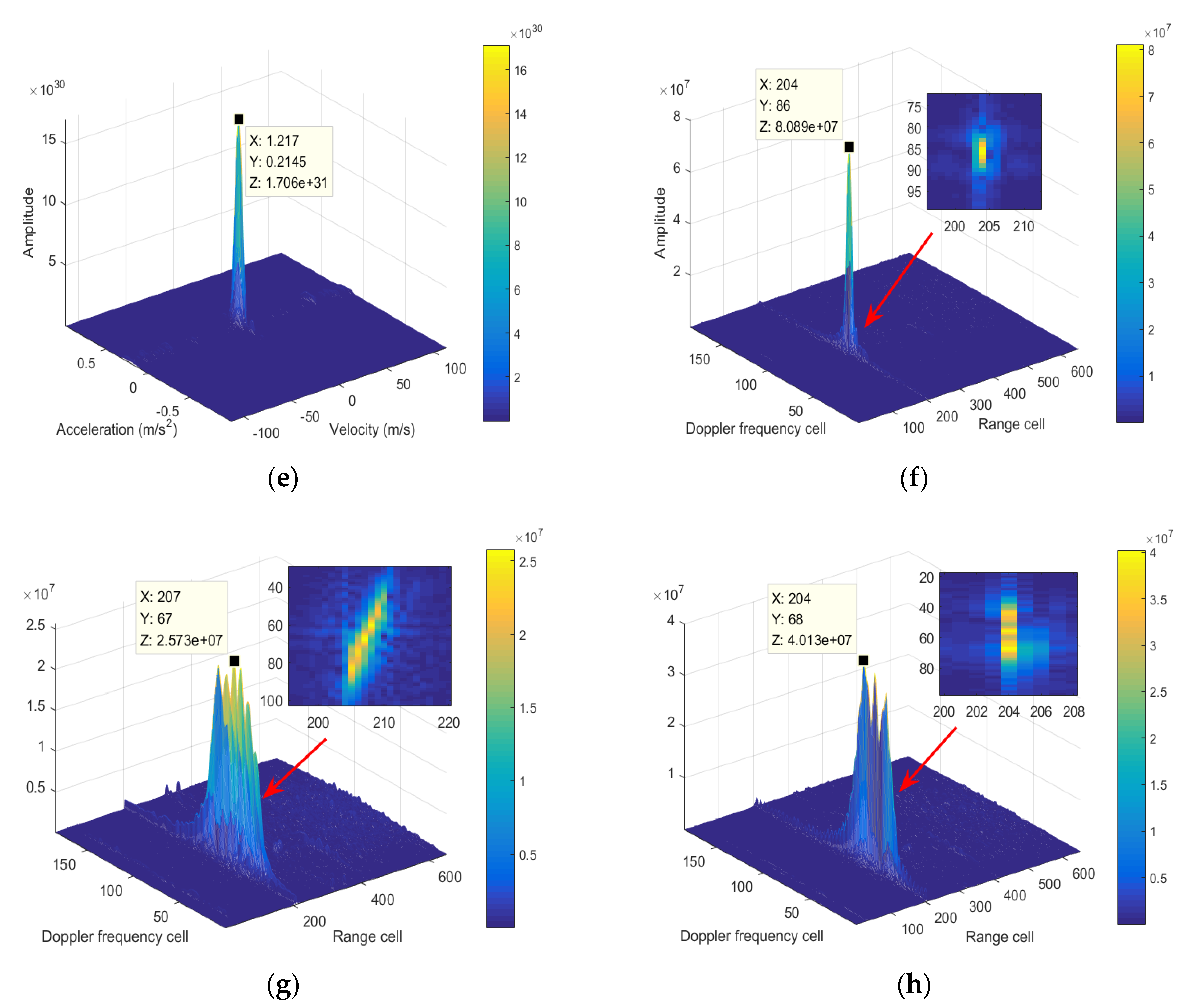
| Range Cell | Velocity (m/s) | Acceleration (m/s2) | Peak Value | |
|---|---|---|---|---|
| MTD | 207 | −0.279 | - | |
| SCIFT | 204 | −0.283 | - | |
| FD-SoPD | 204 | 1.217 | 0.2145 |
© 2019 by the authors. Licensee MDPI, Basel, Switzerland. This article is an open access article distributed under the terms and conditions of the Creative Commons Attribution (CC BY) license (http://creativecommons.org/licenses/by/4.0/).
Share and Cite
Jin, K.; Lai, T.; Wang, Y.; Li, G.; Zhao, Y. Coherent Integration for Radar High-Speed Maneuvering Target Based on Frequency-Domain Second-Order Phase Difference. Electronics 2019, 8, 287. https://doi.org/10.3390/electronics8030287
Jin K, Lai T, Wang Y, Li G, Zhao Y. Coherent Integration for Radar High-Speed Maneuvering Target Based on Frequency-Domain Second-Order Phase Difference. Electronics. 2019; 8(3):287. https://doi.org/10.3390/electronics8030287
Chicago/Turabian StyleJin, Ke, Tao Lai, Yubing Wang, Gongquan Li, and Yongjun Zhao. 2019. "Coherent Integration for Radar High-Speed Maneuvering Target Based on Frequency-Domain Second-Order Phase Difference" Electronics 8, no. 3: 287. https://doi.org/10.3390/electronics8030287
APA StyleJin, K., Lai, T., Wang, Y., Li, G., & Zhao, Y. (2019). Coherent Integration for Radar High-Speed Maneuvering Target Based on Frequency-Domain Second-Order Phase Difference. Electronics, 8(3), 287. https://doi.org/10.3390/electronics8030287