1. Introduction
Application and storage architecture within data centers are becoming more complicated in recent years. As shown in Reference [
1], the large-scale online data intensive services, high-performance deep learning networks, modern telecommunication central office networks and high-speed distributed pools of Non-Volatile Memory Express storage are the four critical data center use cases which are stressing the data center network. These applications raise increasingly demand for high throughput and low latency in data center network, which are generally regarded as two important goals for data center design [
2]. Traditional network protocol, such as standard TCP/IP stacks, is designed for the wide-area networks, with high latencies and high CPU overhead [
3] and cannot meet the demands in the data center. To address this problem, much work has been done around these two goals [
4,
5,
6] for data center.
RDMA is an approach that can meet these demands in a data center. It is designed to solve the delay of server-side data processing in network transmission. At present, the mainstream transport protocol of RDMA over Ethernet is RoCE, which is based on the UDP. Compared with TCP protocol. UDP protocol is faster and occupies less CPU resources but it does not achieve reliable transmission. Once packet loss occurs, it can only rely on the upper layer protocol to check and recover, which will greatly reduce the performance of RDMA. The protocol only achieves good performance when running over a lossless network. RoCE relies on PFC to support a lossless environment in the layer 2 networks.
PFC is a coarse-grained port-based mechanism to avoid packet loss. It can cause many network problems such as congestion spreading [
7] and deadlocks [
8]. Congestion is the primary source of packet loss in the network. It can lead to serious performance degradation [
9]. Therefore, PFC scheme should be triggered as a last resort. A congestion control which operates efficiently can alleviate these problems of PFC.
Two broadly adopted practical approaches to support congestion control are end-to-end congestion control and network-assisted congestion control. In an end-to-end congestion control approach, the network layer does not provide explicit support to the transport layer for congestion control purposes, such as the congestion control mechanism in TCP protocol. With network-assisted congestion control, network-layer components (i.e., routers) provide explicit feedback to the sender regarding the congestion state in the network. An example of network-assisted congestion control is the ATM available bit-rate (ABR) congestion control [
10]. Several new congestion control schemes are proposed to improve performance in data centers, such as QCN [
11], DCQCN [
12] and so on. QCN is a flow-level congestion control scheme which is enabled within layer 2 networks and is incompatible with layer 3 networks. DCQCN is an improvement of QCN, extending the QCN to L3 networks. However, DCQCN uses a three-point algorithm architecture which sends congestion feedback from the receiver to sender. It may suffer longer round-trip-time for the ECN (Explicit Congestion Notification) control loop when the data center becomes larger with more switches and more layers in the network.
We design a congestion control protocol—called P4QCN—which extends the QCN based on P4 for the purpose of alleviating problems of PFC within a lossless network. P4 [
13] is a programming language mainly used for data planes to provide instructions to the data forwarding plane equipment (such as switches, network cards, etc.) how to handle data packets. By the aid of these features of the programmable data plane, P4QCN can achieve a flow-level, rate-based, network-assisted congestion control protocol. Extending QCN protocol to IP-routed networks is not easy under the traditional network architecture. However, in the context of programmable data plane, we can flexibly achieve such extending. P4QCN extends the QCN protocol to make it compatible with IP-routed networks based on framework of P4 and adopts a two-point algorithm architecture which is more effective than the three-point architecture used in DCQCN.
The paper is organized as follows. In
Section 2, we list the related work of congestion control in the data center network and the inadequacies of the existing design. The detail design and the implementation model of P4QCN is presented in
Section 3. We introduce the CP-RP architecture of algorithm and the implementation model of P4QCN based on programmable data plane and PISA (Protocol Independent Switch Architecture). In
Section 4, we introduce the simulation experiment using mininet and the performance results of P4QCN. In
Section 5, we summarize our work and discuss the future work.
2. Related Work
Research revolving around congestion control, applied to high performance data center networks has already been in progress for many years, some of which have been widely used in the data centers network. We will present the related work historically, as it may be useful for us to understand the relevant research.
2.1. RDMA Networks: InfiniBand, RoCE, iWarp
Compared with the traditional network protocol, RDMA does not need the intervention of an operating system. So RDMA can easily achieve ultra-low latency and ultra-high throughput transmission between endpoints. In a word, RDMA has three main characteristics: CPU offload, kernel bypass, zero-copy.
RDMA has three different hardware implementations: (1) InfiniBand [
14] is a network designed specifically for RDMA that guarantees reliable transmission at the hardware level. InfiniBand network has a good performance in the throughput and latency, however it uses the custom switch and NIC, so the cost is very high. Meanwhile, the InfiniBand networking stack cannot be easily deployed in modern data centers. InfiniBand is not compatible with IP and Ethernet technologies. (2) RDMA over Converged Ethernet (RoCE) [
15] has been defined to enable the RDMA over the IP and Ethernet. RoCEv2 [
16] inherited the philosophy of InfiniBand which needs a lossless Layer 2 network to simplify the transport protocol. PFC [
17] is been used in the RoCEv2 to achieve the lossless layer 2 network. RoCE is deployed on a large scale in the data center in reality due to technical and economic reasons [
18]. (3) iWarp [
19] is also an Ethernet-based RDMA technology which involves a different concept to InfiniBand and RoCE. iWarp protocol is designed to handle packet loss efficiently rather than making the Layer 2 network lossless. To ensure the generality, iWarp implements the entire TCP/IP protocol stack on the NIC. However, the full implementation of TCP/IP requires multiple translation between RDMA abstraction and TCP abstraction. As a result, the iWarp is more complex than the RoCE and has a higher cost and a lower performance [
20].
2.2. Priority Flow Control
PFC, which is also referred to as Class-based Flow Control, is a mechanism that prevents frame loss that is due to congestion. When the queue length exceeds the set threshold, the switch sends a pause frame to the upstream switch. When the congestion is mitigated (the queue length comes under the threshold), a resume frame is generated to restart the transmission. PFC can achieve a lossless network when configured correctly.
PFC is a coarse-grained mechanism which can lead to some problems as shown in Reference [
21]. For example, as shown in
Figure 1, when the congestion occurs in the S1 switch and the queue size of the ingress port exceeds the threshold, a PFC PAUSE frame will be sent to the upstream switch (L1) due to the cascading effect of PAUSE frame and switch L1 stops sending data to switch S1. Because PFC will stop all traffic in a particular traffic class at the port, packet from h21 are also suspended, even if the destination port of the data stream from h21 is not congested. The phenomenon is known as head-of-line blocking. The cascade effect of the PAUSE frame can also lead to congestion spread.
The PFC mechanism itself provides the class of priority to address the Head-of-Line blocking problem. However, the protocol only supports 8 priority classes. When the topology and senders are expanding, the performance will be bad. Furthermore, flows within the same class will still have the same problems shown above.
2.3. Quantized Congestion Notification
QCN is a congestion control mechanism by sending congestion feedback from switches to end hosts. QCN provides congestion control based on network feedback (similar to DCTCP [
22]/ECN [
23]) but operated at the Ethernet layer and does not isolate incast [
24].
Basic QCN algorithm is consist of 2-point architecture: Congestion Point (CP) and Reaction Point (RP). CP is the point where the congestion occurs, it is responsible for sampling frames that are being sent in the buffer, computing and quantizing the feedback (Fb) value, RP is the point where the sending rate of a flow is changed due to congestion signals. When congestion message arrives, the data source performs multiplicative decrease of the sending rate. Also, when there is no congestion message arrives, the data source will gradually increase its transmission rate to detect the available bandwidth or recover the “lost” rate due to congestion. QCN also provides a three-point algorithm. The algorithm using three-point architecture shifts part work (generating feedback packets) of CP in two-point architecture to the destination as the Notification Point (NP) point.
QCN is a congestion control mechanism which is easy to deploy and has light resource requirement. QCN enables flow-level congestion control which is fine-grained compared to PFC, it resolves some problems of PFC mentioned above. However, QCN is designed within an L2 domain which identify flows using source/destination MAC address, therefore, it is not compatible with IP-routed networks.
2.4. Other Relevant Protocol
Some other congestion control protocols are also proposed, such as DCQCN [
12], TIMELY [
25] and IRN [
21]. DCQCN is a rate-based, end-to-end congestion control protocol, that builds upon QCN and DCTCP. It consists of RP, CP and NP. The arriving packets are marked by the CP algorithm when the queue length exceeds the threshold. NP receives marked packets indicating congestion in the network and then sends Congestion Notification Packets (CNP) [
14] back to the sender. When the RP gets an CNP, it reduces its sending rate of traffic injection into the network. DCQCN uses the ECN to feedback the congestion information to the sender. It may suffer longer round-trip-time for the ECN control loop when the data center becomes larger with more switches and more layers in the network. Larger networks also exist more data in-flight, making it difficult to absorb bursts of traffic before ECN congestion control takes effort.
IRN (Improved RoCE NIC) [
21] provides another solution, which allows packet loss and improves network performance by adopting a more effective packet loss recovery mechanism. It makes two key changes to current RoCE NICs: (1) improving the loss recovery mechanism; (2) basic end-to-end flow control mechanism. IRN eliminates the need for PFC. In the diversified network environment, the performance degradation caused by packet loss is different, especially in some elephant-dominated networks, packet loss recovery will aggravate congestion.
PFC, ETS (Enhanced Transmission Selection) [
26], QCN and DCBX (Data Center Bridging Exchange Protocol) [
26] are a set of enhancements to the Ethernet local area network communication protocol for use in data center environments. These technologies are indeed complementary and typically used in combination. ETS is to enable multiple traffic types to coexist in the same network. DCBX is an extension protocol based on LLDP (Link Layer Discovery Protocol) used to automatically negotiate and configure PFC, ETS and CN among devices.
Some other congestion control protocols such as DCTCP [
22]/TCP-Bolt [
27] are window-based algorithms. They are complex in implementation and implemented in end host stacks and thus have high CPU overhead and high latency.
3. Modeling of P4QCN
In the past few years, one of the most active areas in computer networking is Software Defined Networking (SDN) [
28] which separates the control-plane and the data-plane. The separating of the control-plane and data-plane brings additional flexibility of the networks. However, SDN still assumes that the behavior of the network data-plane is fixed. This hinders the further innovation of the network. In this context, programmable data plane technology has emerged. Programmable data plane has the characteristics of openness, flexibility and protocol independence. Based on the programmable data plane, we design P4QCN algorithm which is a network-assisted and flow-based congestion control protocol and extends the QCN protocol to IP-routed networks. P4QCN is based on P4 [
29] and is implemented in the P4-Capable switch.
As mentioned in
Section 1, one of the main contributions of P4QCN is extending the QCN protocol to L3 networks within the framework of P4. Flows are defined using source/destination either MAC address or IP address and then we achieve a congestion control algorithm based on QCN. The P4QCN architecture is consist of two points: RP and CP.
3.1. Overall Architecture of P4QCN
P4QCN is a two-point congestion control architecture including RP and CP as shown in
Figure 2. Compared with three-point architecture, CP on switches in the two-point architecture sends congestion feedback packet directly to RP on the source. Therefore, it is more effective and less complex than three-point architecture, where feedbacks are sent via NP. Next, we introduce the CP and RP algorithms in detail.
3.1.1. CP Algorithm
As shown in
Figure 2, the CP algorithm deploys on switches in the network. It mainly achieves two functions: (1) predicating the congestion status; and (2) generating feedback packets. The probability to send feedbacks is shown in Equation (1). When the queue size in the egress port exceeds
, the feedback packets are generated at a certain probability. When the queue size reaches to
, the feedback packets will be generated and sent to RP at a probability of one hundred percent.
is the probability of sending a feedback packet,
is the current queue size on the egress port indicating the current congestion status.
As shown in
Figure 3, the probability of feedback packet generation is defined similar as in QCN [
24]. Since PFC protocol is the last resort to ensure the achievement of lossless network, P4QCN should been triggered before PFC. It means that packets in flight during P4QCN message taking effect should been taken into account. PFC protocol is triggered when the queue size in the ingress port exceeds the
. P4QCN is designed to reduce this occurrence.
When the P4QCN mechanism is triggered as the growth of queue size, the feedback packet (FBP) is generated according to CP algorithm. ECN field of FBP is set to “11” to indicate congestion. We can extract the source/destination IP address from the arriving packet at egress queue based on PISA (Protocol independent switch architecture) in programmable data plane. The congestion flow is defined by the source/destination IP address. Then the information of the congestion is sent to the source of the flow. In order to avoid frequent transmission of feedback information, the congestion point generates at most one feedback packet every N micro-second for a same congestion flow when the P4QCN is triggered.
The algorithm of CP is implemented by the original P4 program. The P4 program of P4QCN is then compiled and configured onto the P4 target (bmv2 in our testbed). We provide some definitions and phrase of P4 [
30] so that the description of the model can be understood easily.
Header definitions: the format (the set of fields and their sizes) of each header within a packet.
Parser: the permitted header sequences within packets.
Pipeline layout and control flow: the layout of tables within the pipeline and the packet flow through the pipeline.
Figure 4 describes the CP algorithm based on protocol independent switch architecture (PISA) of P4. It is based upon an abstract forwarding model consisting of a parser and a set of match+action table resources, divided between ingress and egress. P4 is a declarative language for expressing how packets are processed by the pipeline of a network forwarding element such as a switch, NIC, router or network function appliance.
When the queue size of egress exceeds the threshold of P4QCN, the packet entering the egress queue is cloned to ingress. In ingress, the ECN field of the packet is set to “11” and then the packet is sent to the source of the packet by modifying the destination IP address. Furthermore, when the ingress queue size exceeds the threshold of PFC, the packet is cloned to ingress and then be modified to the upstream switch to pause the sending of the upstream. The above operation is implemented by defining match+action table and controlling the flow logic in P4. The CP point is implemented in P4 language. The code of CP algorithm is compiled into a configuration file and loaded on the forwarding device.
Table 1 shows the header and metadata fields extracted from packet by parser in P4 terminology. The parser identifies the headers present in each incoming packet.
3.1.2. RP Algorithm
As shown in
Figure 2, the RP algorithm deploys on ending hosts in the network. When the RP receives a FBP, it reduces sending rate of traffic injection into the network and records the rate before receiving feedback information as a target rate for fast recovery. The algorithm of reducing rate is shown in Equation (2), where
is the rate before receiving FBP,
is the target rate for fast recovery and
is the current rate. β is the rate reduction factor which is a constant, representing the degree of rate reduction. The maximum value of β is set to 1, so the maximum rate reduction is half of the original sending rate when a feedback packet is received.
The source limits its transmission rate based on the FBP received from CP. Then, the source will gradually increase its transmission rate to recover the “lost” rate due to congestion to detect the available bandwidth. The process of increasing the rate includes two stages: the fast recovery and the active increase.
When the sending rate is reduced, a byte counter is reset and enters the fast recovery process. The fast recovery stage consists of N cycles. At the end of each cycle,
remains unchanged and
is updated according to Equation (3). The byte counter records the number of sending byte during one cycle and when the value of bytes counter reached a threshold, it records one cycle. The value of N is suggested to set to 5 in QCN. The process of rate increase in fast recovery is shown in
Figure 5. When the N cycles has been completed, the stage of active increase begins to detect the available bandwidth.
After five cycles of fast recovery, the byte counter enters the active increase. This stage is used to find redundant available bandwidth. RP performs operations as shown in Equation (4).
is a constant which is set to 5Mbps in P4QCN protocol.
The RP algorithm is implemented by a finite state machine (FSM). The FSM contains three states and the migration between them. Three states of the FSM represent three processes of RP algorithm: rate reduction, fast recovery and active increase.
Each host runs an instance of the RP process, which receives the feedback message from CP point. When receiving the feedback packet, the RP processor reduces the sending rate of the flow injection into the network and records the rate before receiving feedback information as a target rate for fast recovery. When RP process enters the fast recovery, the sending rate increases as the Equation (3) describes. After N cycles of the fast recovery, RP process enters the active increase to detect the available bandwidth of the network. The instance of RP process is implemented in python file, the script achieves the function of the FSM described in
Figure 6.
Figure 6 shows the operation of RP algorithm. The finite state machine contains three states and the migration between them. The arrows in the FSM description indicate the transition of the algorithm from one state to another. As shown in
Figure 6, the event causing the transition is shown above the horizontal line labeling the transition and the actions taken when the event occurs are shown below the horizontal line. Rcv (FBP) represents the event of receiving FBP. The FSM is implemented in Python.
3.2. Analysis of P4QCN
As mentioned above, the targets of congestion control algorithm of P4QCN are: (1) ensuring lossless of packet working with PFC and reducing the negative impact of PFC. (2) maintaining cache queue occupancy at a desired value to increase link utilization. In a sense, these two objectives are contradictory. We must ensure that we do not lose packets and also seek for the higher link utilization. It means that the trigger of congestion control mechanism is neither too early nor too late. So the setting of the threshold is important to P4QCN. In addition, packet loss due to internal cache structure of switches should also be taken into account.
3.2.1. Switch-Inner Lossless Mechanism
In order to ensure lossless network, packet loss within the switch should also been taken into account. First of all, let us take a look at where queues will appear in the switch. Theoretically, it is clear that packet queues may form at both the input ports and the output ports. The location and extent of queueing (either at the input port queues or the output port queues) will depend on the traffic load, the relative speed of the switching fabric and the line speed. Input-Queued switch and Output-Queued switch have their own merits and flaws, respectively. Discussions on queuing design is out of the scope of this paper and much research has revolved around this topic. Details of the Input-Queued switch and Output-Queued switch design can be found in Virtual Output Queuing (VOQ) [
31] and Combined Input/Output Queueing (CIOQ) [
32] and so forth.
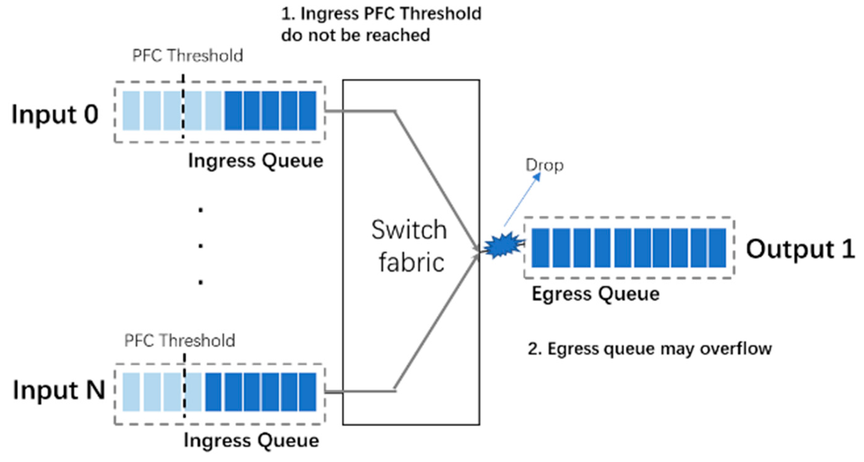
PFC is implemented on the ingress queues of a switch. An example of packet loss within switch is shown in
Figure 7. In the scenario shown in
Figure 7, both input 0 and input N are forwarded to output 1, it is possible that the egress queue has overflowed before the ingress queues triggering PFC. A coordination mechanism between ingress queue and egress queue to ensure a lossless environment within a switch should be taken into account. This coordination mechanism depends on the structure of the switch cache. In this paper, the buffer of the bmv2 switch is shared among all ports.
3.2.2. Setting of Threshold
We now discuss the threshold for triggering P4QCN on egress queue and PFC on ingress queue.
PFC threshold(): PFC is triggered as the last resort to ensure the lossless of network. PFC threshold is the maximum value of the queue size can grow to. To avoid the overflow of the queue, packets that are in flight and sent by upstream switch during processing the PFC PAUSE message should been taken into consideration. Some buffer space (
) should been reserved to receive these packets. Packets in flight for a flow is defined by the bandwidth-delay product (BDP) of the network in P4QCN, as suggested in Reference [
33]. The total switch buffer size is
, there are
n ports in the switch and support 8 PFC priorities. The threshold should follow:
≤
.
P4QCN threshold (): P4QCN should been triggered before PFC. Furthermore, PFC should not be triggered before P4QCN take effect, it means that packets in flight during P4QCN message taking effect should be taken into account. So
. The switch buffer is shared among all ports in bmv2 switch which used in our testbed. P4QCN adopts the threshold setting method used in algorithm DCQCN [
12] which is compatible for shared cache architecture.
<
; we use α = 8.
3.2.3. IP-Enabled Protocol Extension
P4QCN is implemented based on programmable data plane and P4(Programming Protocol-Independent Packet Processors). P4 is a declarative language for expressing how packets are processed by the pipeline of a network forwarding element. It is based upon an abstract forwarding model consisting of a parser and a set of match+action table resources. The parser identifies the headers present in each incoming packet. Each match+action table performs a lookup on a subset of header fields and applies the actions corresponding to the first match within each table.
Since QCN is designed within an L2 domain which identify flows using source/destination MAC address, it is not compatible with IP-routed networks. P4QCN extends QCN protocol to L3 networks within the framework of P4. P4QCN defines flows with either source/destination IP address or MAC address enabled by the parser in P4 model. P4 models the parser as a state machine. This can be represented as a parse graph with each state a node and the state transitions as edges.
Figure 8 shows a simple example of the parser, the source/destination IP address can be extracted from the header of the packet.
The parser produces the representation of the packet on which match + action stages operate. It is the set of header instances which are valid for the packet. Therefore, we can define the headers and parser according to different protocol stack.
The source/destination IP address extracted from the header of the packet will be used in match + action stages to identify the congestion flow.
4. Experiments Results
The system and its implementation of P4QCN is described in
Figure 9. We implement the CP algorithm based on the abstract model of programmable data plane as described in the right part of
Figure 9. The parser graph defines how headers are identified within a packet and produces the representation of the packet on which match + action stages operate. The match + action table and the control flow achieve the logic of CP algorithm. The CP algorithm written in P4 language is compiled into a JSON configuration file and loaded into the data plane forwarding device. At the same time, the API is opened to the control plane. The data plane and the control plane communicate with each other using thrift protocol. RP algorithm implements three processes: rate reduction, fast recovery and action increase on the host ending of networks as described in the left part of
Figure 9. RP algorithm is implemented with Scapy library of Python language.
We simulate a 3-tier datacenter topology in mininet to represent the current data center network. As shown in
Figure 10, there are two spines (S1–S2), four leaves (L1–L4) and four ToRs (T1–T4) in the topology. We use bmv2(behavior model version 2) as the P4 software switch in mininet which is written in C++. We implement each switch as CP Point and each host as RP point.
Limited by the performance of the simulation environment, we conclude that after many experiments the link bandwidth is the most stable when it is below 10 Mbps. We set the bandwidth of the link 7Mbps in our testbed; = = = 11; = 14 (the value of and is the quantization of queue occupancy in the virtual switch model); N = 5; β = 1, = 5Mbps respectively. We extend mininet by modifying the CLI class and Mininet class of mininet and use the extended iperf tools of mininet with a random traffic model for the data center environment. In the random traffic model, any host in the mininet topology randomly initiates a UDP data stream to another host with a random flow size. We use random traffic model to generate background traffic in the data center network in our experiments. The congestion may happen on T4 switch in our experiments. We send a UDP flow with 4M/s from host11 to host41 via iperf and meanwhile set the sending rate of background traffic with 2M/s, 3M/s, 4M/s and 5M/s respectively to introduce different level of congestion on T4 switch.
4.1. Preliminary Verification of P4QCN
We deploy the P4QCN on the testbed. The CP algorithm is deployed on the bmv2 switch and the RP algorithm is deployed on the ending host. When congestion occurs, we capture the packet which is marked with “ECN” with Wireshark. As shown in
Figure 11, “ECN” is set to “11.” The sending rate of the source is recorded in the
Figure 12, we can see the process of “rate reduction” “fast recovery” and “active increase.”
4.2. Comparative Analysis
We set up five groups of comparative experiments to verify the performance of P4QCN from different perspectives.
4.2.1. P4QCN Compared with UDP and TCP
We compare the performance metrics of UDP flows with and without P4QCN. As shown in
Figure 13a,b, we can see that when congestion occurs, the packet loss with P4QCN is much lower than the case without P4QCN, in particular, when congestion level is high. It shows that P4QCN can effectively reduce the packet loss. In
Figure 13a, the results indicate the delay with P4QCN increases a bit compared with UDP on the other hand.
We also compare the latency of TCP flows with P4QCN in
Figure 13a. The results show that the TCP congestion control and loss recovery mechanism causes higher latency than P4QCN.
4.2.2. P4QCN Compared with P4QCN + PFC
We implement the PFC mechanism in the programmable data plane. In this group of experiments, we compare the network performance of P4QCN only with P4QCN and PFC both deployed simultaneously.
As shown in
Figure 14a,b, when P4QCN and PFC are deployed together, the latency increases compared with P4QCN is deployed alone. This is due to additional delay introduced by PFC. The results of
Figure 14b show packet losses with P4QCN, therefore, P4QCN alone cannot achieve lossless.
From this set of comparative experiments, we can conclude that: (1) P4QCN deployment alone cannot achieve lossless, it must be deployed with PFC to achieve a lossless network; (2) P4QCN can only reduce the number of PFC triggers but it cannot completely avoid PFC triggers.
4.2.3. P4QCN + PFC Compared with PFC
In this set of experiments, we compare the case of both P4QCN and PFC deployed with the case only PFC deployed in terms of latency. Both cases can achieve lossless but P4QCN + PFC can reduce the latency compared with PFC as shown in
Figure 15. This is because P4QCN effectively reduces the number of PFC triggers. The results of experiments show that P4QCN is effective in improving some of the negative effects of PFC. Therefore, P4QCN is helpful to improve the performance of RoCE network when combined with PFC.
4.2.4. CP-RP Architecture Compared with CP-NP-RP Architecture
P4QCN uses two-point architecture which contains CP and RP, while some algorithms such as DCQCN use a three-point architecture which contains CP, RP and NP (Notification Point). We implement a three-point architecture algorithm in the programmable data plane model. The algorithm using three-point architecture shifts part work (generating feedback packets) of CP in two-point architecture to the destination as the NP point.
The results of experiments are shown in
Figure 16a,b. Compared with three-point, two-point architecture has lower latency and smaller packet loss rate. In three-point architecture, the congestion information needs to go through a longer path and then feed back to the source. Therefore, the congestion control algorithm takes longer time to take effect. So, two-point architecture is more efficient.
4.2.5. Bandwidth Utilization Comparison under Different Thresholds
Next, we compare the bandwidth utilization of P4QCN and PFC and the impact of threshold on bandwidth utilization by setting different thresholds of P4QCN (
) and PFC (
). The value of threshold is the quantization factor of the queue occupancy in the virtual switch model. In the case of slight congestion, the results of experiments are shown in
Figure 17.
We compare the bandwidth utilization of P4QCN and PFC deployed separately under different thresholds to further analyze the impact of these two different mechanisms on network performance. The results in
Figure 17 show that the P4QCN has a higher bandwidth utilization than PFC when the threshold is lower. They are getting closer when the threshold is getting higher. This is because, when the PFC is triggered, the upstream switch will be paused to send packets while P4QCN reducing the sending rate of the source. Therefore, PFC is more coarse-grained, which has a negative impact on network performance.
The results in
Figure 17 also show that the higher the threshold of
is, the more the bandwidth utilization would be. P4QCN is triggered more frequently when the threshold is getting smaller, as P4QCN reduces the sending rate of source which leads to a reduction of the bandwidth utilization. PFC has the same situation as P4QCN.
As the resource needed for computing and communication in P4QCN is comparable to that in QCN/DCQCN with either virtual or hardware switches, we expect our proposed P4QCN algorithm in real networks will achieve the same performance as in mininet environment in terms of network latency and bandwidth utilization, however higher processing speed.
5. Conclusions and Future Work
RDMA over Ethernet namely RoCE over the UDP is the current transport protocol designed to achieve high performance in the datacenter network. In the paper, we propose P4QCN, which is a flow-level, rate-based, network-assisted congestion control protocol, implemented in the framework of P4. It extends the QCN protocol to IP-routed networks and uses two-point (CP-RP) architecture to reduce the end-to-end latency and the packet loss rate.
We verify the performance of the P4QCN algorithm and compare it with other algorithms in the simulation network environment. The experiments are limited by the performance of virtual switches. In future work, we will verify P4QCN in the real network.


