1. Introduction
Cloud data centers and cloud services providers guarantee CPU, memory, and storage for tenant virtual machines. However, they fail to ensure cloud network bandwidth availability, preventing tenants from achieving predictable running application performance due to limited network-bandwidth availability. Applications are often deployed in a traditional data center, claiming specialized network topology and routing mechanism to achieve better performance and infrastructure expense reduction. Unfortunately, VDC suffers deficient performance from the one-size-fits-all routing scheme prevalent in data center networks.
While modern protocols support multiple paths through schemes, such as Equal-Cost Multi-Path routing (ECMP) [
1,
2], in which each path continues to be selected using the same optimization metric, higher requirement cloud tenants should retain the ability to self-define both their network topology and forwarding path according to application characteristics set in the cloud data center [
3]. The authors of [
4], devoted to controlling logic over cloud network functions, solved this issue by installing flowtable entries in physical switches; however, it fails to maintain scalability. Moreover, the shared nature of the network in the multi-tenant cloud data center implies network performances for VDC vary significantly.
No internal traffic control mechanisms exist in popular cloud services providers, such as Amazon EC2 [
5], Rackspace Cloud [
6], and Microsoft Azure [
7], not to mention the fine-grained traffic control mechanisms for the specific service type. Thus, the imperative exists to provide bandwidth guarantees for VDC under the premise of application-aware networking and the feasibility of fine-grained traffic control for tenants in cloud data centers, offering similar performance guarantees exhibited in the enterprise; therefore, the challenges for such scenario are considered below.
Tenants self-defined network scalability: Recent research on cloud data center virtualization has made it possible to decouple the VN configuration from the underlying physical network fabrication where tenants can self-define VDC network topology [
8,
9] and allocate arbitrary subnet address to the designated virtual machine (VM) with the full address space virtualization provided. Gateways realize access control among various subnets. However, self-defining packets forwarding rules in independent VDC, promoting application-aware networking, has failed to be implemented in popular cloud data centers. Even though software-defined network technology can be employed to implement network virtualization to achieve application-aware networking [
10], it does not apply to the cloud environment due to its original, considerable services revealing a severe switch state maintenance scalability problem. Therefore, allowing tenants to embrace application-aware networking power in the cloud data center addresses an onerous existing challenge virtual data centers need to solve.
Better VNE schemes and VN to PN mapping: A prerequisite for supporting bandwidth guarantee in cloud datacenter holds appropriately allocating bandwidth resource in the physical network among VDCs to meet sufficiently tenant’s SLA demands. Such an approach can be divided into the following two parts: mapping virtual VDC machines to a physical node and mapping the virtual link to physical link. This is usually considered a multi-commodity flow problem, demonstrating an NP-hard single unsplittable source flow [
11]. Through the years, several virtual network mapping heuristics have been proposed; in our research, we found the four most profound in cloud datacenter [
12,
13,
14,
15]. To the best of our knowledge, virtual network mapping algorithms adopt serialized VM-centered VN to PN mapping patterns, requiring each VM to be first mapped to a suitable position to fulfill the given conditions. When allocating a VDC with thousands of VMs in cloud datacenter hosting over 100,000 computing nodes, which takes approximately 100s. Apparently, the virtual network possesses enough space to map a lifting algorithm. Tenants desire an efficient allocation procedure. Hence, how to design a VDC allocation algorithm improving allocation efficiency poses another challenge to overcome.
This paper presents GANA-VDC, a network virtualization framework supporting bandwidth allocation in cloud data centers. In this work, we observe primarily the network remains physically interconnected as a fat-tree to a second layer scalable and fault-tolerant routing and forwarding protocol, for cloud data center using commodity switches [
16]. However, the commodity switches closure restricts internal information access and control, prohibiting application-aware networking. By deliberately replacing commodity switches with OpenFlow-based switches [
17], we offer a flexible physical network infrastructure. Flowtable capacity typifies a limited resource, as flowtable capacity remains scarce. Given the cloud datacenter magnitude, the flowtable cannot practically accommodate the flow entry volume. OpenFlow permits scalable flow entries with the switches; thus, source routing was chosen as the preferred method. With source routing, even though one benefits from the switches’ statelessness completely unaware of VDC and bandwidth reservation, one cannot avoid the challenge related to the inability of a tenant to enable properly fine-grained traffic on specified and concrete service type. As OpenFlow v1.3 protocol [
18] offers a table of entries defining the flow meters to implement complex QoS frameworks, e.g., DiffServ [
19,
20], the redundant flowtable-space is amortized on demand with pay-as-you-go pricing. Combining source routing with flowtable can be adapted to the diverse SLA requirements, and thus, two principal mechanisms in VMSG perform routing and forwarding: Firstly, one provides the fundamental bandwidth guarantee using source routing, the other targets fine-grained QoS relying on flowtable division.
Datacenters tenants should be able to select their Self-Defined Network (SDN) controllers, e.g., OpenDaylight [
21], NOX [
22], and Floodlight [
23]. The underlying physical network remains transparent to the network VDC controllers. To achieve this, we use switch-level virtualization, such as FlowVisor [
10], in which several isolated networks with potentially differing forwarding and addressing tenants mechanisms are built on the same hardware forwarding plane. However, the challenge arises to support many tenants each characterizing a different topology and alternative application controller. The link service is the underlying network service the SDN controller eventually provides. It starts with learning physical links initially created between switches in the control domain utilizing instructing switches to send Link-Local Discovery Protocol messages (LLDP) out of all ports connected once the service is initiated. Once the number of tenant controllers expands to a particular scale, FlowVisor fails to sustain the overhead. In this work, we propose the design of hierarchical state maintenance and query algorithm for relieving the burden of FlowVisor. The state of high layer tenant link service can be constructed from the intermediate one conserved by low tenant link service, reducing the overall request number tenant link services send to each physical network switch.
Efficient virtual network mapping to the physical network crucially gives good user experience, especially when the scale of VDC to-be-allocated proves enormous. As mentioned above, mapping VN to PN is an NP-hard problem. Therefore, we propose a heuristic switch-centered based VN to PN mapping approach to solve the VDC allocation issue in polynomial time. Converse to VM centered approaches, this method is parallel and more efficient. Our work includes the following contributions:
Designing a network virtualization framework for enabling application-aware networking with bandwidth VDC guarantees.
Maintaining VN mapping topology on PN, proposing the GANA model, a switch centered based VN to PN mapping scheme.
Introducing hierarchical state maintenance and query algorithm for relieving the limitation of FlowVisor employed VDC guarantees.
The remainder of the paper is organized as follow. In
Section 2, we present related work. In
Section 3, we introduce the system model and give definitions of related concepts. In
Section 4, we unveil the GANA-VDC framework. In
Section 5, we outline the experiment results, evaluation, and performance analysis. In
Section 6, we further discuss our work.
Section 7 concludes the paper.
2. Related work
Researchers in cloud datacenters have concentrated on providing a sophisticated solution for supporting VN performance separation in the cloud data center. Presenting diverse bandwidth allocation VN models, such as traffic matrix [
13]; engendering a fixed bandwidth, e.g., the hose model with invariable bandwidth [
14] or where the bandwidth varies with time [
24] or a TAG model based on a communication structure between applications [
19]. Choosing from this variety, researchers design their proper version of VN to PN mapping algorithms. However, the above works only emphasize practical VN models conveying the communication relationship among VMs and VN to PN mapping efficiency, and none of these proposals intend to provide fine-grained QoS for VDC. Currently, despite self-defining network topology, VDC tenants cannot self-define control networks logic. We summarize the requirements to consider in such a scenario in the cloud data center.
Virtualization: According to Faizul et al., a virtualized data center is a data center where some or all of the hardware is virtualized [
25]. This is achieved by simply ensuring the different components are isolated and independent virtual instance [
25]. This process faces a unique problem known as VNE. Virtual Network Embedding (VNE) is a common challenge faced by different researchers. Fischer et al.’s proposal is one of the viable solutions to this process. They highlighted the importance of self-configuration and organization of the network [
26]. According to the authors, good service is computed based on either QoS, economic profit or survivability over energy-efficiency to the security of the network. The most palatable procedure, in this case, is to ensure virtual resources are allocated to physical infrastructure in the most optimal method [
26]. These resources are allocated to nodes as well as links (Virtual Node Mapping (VNoM) and Virtual Link Mapping (VLiM)). To further simplify the challenge, the authors suggested that all VNE approaches should be categorized as “static or dynamic”, “centralized or distributed” and “concise or redundant”.
Optimization: Optimization is therefore key in the virtualization process. The authors detailed this in their editorial into different steps. By considering small instances of the challenge, the authors discussed exact solution, heuristics-based solution and metaheuristic solution. Besides this, embedding metrics must be considered, including quality of services metrics, cost-related metrics and resilience metrics [
26]. Quality of service is related to this topic where different metrics define the proposition. QoS is derived from the following entities, which are used to discuss a network: path length, stress level, utilization, throughput, delay and jitter [
26].
IP Addressing: Preferably, a multi-tenant network allows a tenant to design the VN abstraction where the tenant acts as the sole occupant of the physical network (PN). This signifies second layer (L2) and third layer (L3) addresses must remain tenant definable. For address isolation, every VDC may create multiple subnets, where each has a personal IP address that can interfere with other VDC addresses. VM communications remain within the same VDC managed by a distinguished controller. By default, for the sake of network security, different VDCs do not allow their VMs to communicate. In such a framework, the proper way to communicate will then be achieved through L3 gateways. Likewise, VM communication in VDCs with private networks or computers on the Internet also go through those gateways. The authors of [
27] presented an approach for encapsulating second layer L2 packets to send them over a scalable L2 fabric combining both the L2 and L3 layers through encapsulation simultaneously benefitting from using both characteristics. Such encapsulation provides full address space virtualization.
Self-defining Topology: Tenants should be able to build network topologies that can deploy necessary VDC applications. Virtual switches remain interconnected, similar to practical commodity switches, providing limited interfaces link VMs and the corresponding restricted bandwidth, forming the network structure.
Application-aware Functionality: As more applications migrate to the cloud and best effort QoS no longer entails a satisfactory approach, a new breed of intelligent networks is necessary. Application-aware networking is the answer. The networks need to sophisticatedly delve deeper into tenant-applications to enhance high performance. The ability to benefit from application-awareness depends upon SDN, particularly separating the data plane from the control plane, and thus facilitates on the fly network architecture reconfiguration and dynamic control of efficient resource allocation [
28]. This opens application-aware networking making VDC-based application-aware networking a crucial and attractive cloud datacenter approach.
Tenants Oriented QoS: Cloud data centers share environments with a high multiplexity level to benefit from cost-efficiency and scale where the same cluster allows for tasks from various tenants and VMs to coexist [
29]. Cloud data centers have strong requirement to enforce performance isolation among tenants, but the current existing mechanisms fall short on data center network I/O resources, as performance predictability remains a crucial concern for customers assessing a transfer using cloud data centers. Cloud data centers offer tenant-oriented QoS support, including providing bandwidth guarantee to insulate inter VDCs and enabling fine-grained traffic control mechanisms for intra-VDC.
Quality of Experience (QoE): Cases where security systems contribute to the reduced or poor performance of a system are common. Often, developers forego quality as opposed to having security threats. A proposal by Moayad et al. [
30], however, seeks to resolve this challenge [
30]. They proposed an intrusion detection system that does not compromise the user requirements of quality of service (QOS) and quality of experience (QOE). This is achieved by providing a dedicated connection with specific capabilities. According to the researchers, this is achieved by creating clusters that provide specific services. The cluster heads will then communicate with trusted third-party entities (TTPs), which will ensure the system remains safe. The researchers’ framework is based on detecting intrusive nodes through Deep belief and Decision Tree-based Hybrid Intrusion Detection System.
Security: Several security threats affect bandwidth allocation or rather manipulate the bandwidth allocation. One major case is the Black-Hole (B-H) attack. This is case where a node receiving data packets drops or blocks the data packet as opposed to sending it the next recipient or receiving node. This threat was highlighted by Safa et al. [
31]. The authors proposed a system that evaluates the validity of a node based on its selfishness, energy, honesty and intimacy. This is achieved by detecting the B-H cluster heads, where re-clustering is done to ensure the legitimate cluster heads (CHs) are in use. The process of re-clustering is purely based on a trust score, which, according to the trio, is the best way of distinguishing between normal and malicious devices. In their work, the authors used a hierarchical trust score evaluation method [
31]. The authors researched on the performance of different thresholds divided into 20%, 30%, 40% and 50%. At 50%, the system was most stable while at 20% it was most vulnerable with all the CHs being considered as B-H nodes.
Data Aggregation: In [
32], the authors worked on a system capable of recognizing intrusion for wireless sensor clusters in critical infrastructure. Sensory data from other sensors in the corresponding cluster are aggregated in the cluster head. This information is then sent to a centralized sink. Safa et al. confirmed that data aggregation is used to measure the aggregator’s trust score. This score is based on the score of each sensor in relation to the trust evaluation between aggregator and the sensor [
32]. By using the trust value of a node and trust evaluation between the aggregator and the node. We can therefore calculate the trust value of the aggregator. The system utilizes two parallel intrusion detection subsystems where the aggregated traffic is used as input.
FlowVisor: FlowVisor is one of the first hypervisors developed. As documented by Arsany et al., FlowVisor is used for virtualizing and sharing resources on a network based on the OF protocol [
33]. Research work around this concept is meant to improve the usability of the same. According to the authors, the goal of FlowVisor is to provide a hardware abstraction layer that facilitates innovation above and below the virtualization layer. The software controls the access of the tenants’ controllers to the switches. FlowVisor achieves this requirement based on different metrics [
33]. Abstraction and isolation is one of the features that FlowVisor provides; this is done through vSDNs with bandwidth isolation, topology isolation, switch CPU isolation, flowspace isolation, isolation of the flow entries and isolation of the OF control channel [
33]. FlowVisor also compliments the work of SDN controllers and SDN switches. In this case, the latency is overhead to the tenant control operations.
Compared to FlowVisor, Advisor and VeRTIGO provide more or less the same services. According to the author, Advisor improves the functionality of FlowVisor using two procedures. Introducing an improved abstraction mechanism is one of the procedures. This mechanism hides physical switches in virtual topologies [
33]. Besides, the technology also enables the sharing of flow space by multiple slices as an added advantage. VeRTIGO further develops this concept by enabling the vSDN controller to select the desired level of virtual network abstraction. However, this ability also means that the process is more complex and therefore more challenging to diagnose [
33]. FlowVisor has improvements on its usability. This has been termed as enhanced FlowVisor. This new technology resolves the challenge of bandwidth allocation and lack of admission control.
4. GANA-VDC System Architecture
The GANA-VDC model provides a guaranteed bandwidth a VDC specifies and supports more fine-grained VDC service traffic control. This system is built based on Portland layer-2 fabric considerations. Contrary to Portland [
16], in our underlying physical network topology, we use interconnected OpenFlow switches instead of commodity switches. The main work of GANA-VDC implemented in the hypervisor contains four main components (
Figure 4):
Forwarding Pattern Dispatcher: Two forwarding patterns are provided in GANA-VDC where tenants can determine which pattern to use. A parameter passed to Forwarding Pattern Dispatcher component marks the forwarding pattern. Subsequently, GANA-VDC forwards tenant traffic.
Flow Split: In accordance with Clos network theory [
36], since Portland epitomizes a de facto rearrangeable non-blocking network, a non-negligible amount of bandwidth is lost to the collisions on a longer time scale through the number
of paths existing between possible sources and possible destinations where an ECMP-style of flow hashing is leveraged [
1]. Nevertheless, if one carefully schedules the packets sent through possible paths, one can achieve a non-blocking situation. Nevertheless, this remains a challenging problem. To alleviate network blocking, we assume any flow can be split into several smaller flows; the Flow Split component is designed to implement that. The main technique of splitting flow depicts Multipath TCP (MPTCP) [
37]. A Sender must segment and then distribute across multiple sub-flows transmitting a data stream to MPTCP by a VM source. It then must be reassembled into a single data stream before delivering it back to the destination VM. To split flow and define how many sub-flows, we modify the multipath congestion control algorithm in MPTCP in light of the global status of underlying physical network resource utilization. We merely split best-effort flow service with no bandwidth guarantee to achieve an actual non-blocking network, but that discussion will be reserved for future work.
OpenFlow: The OpenFlow component operates according to SDN specifications. Tenants use OpenFlow to control flowtable to offer intra-VDC fine-grained QoS. When different VDCs follow the same devices for forwarding purposes, a conflict in the flowtable entries results due to associated application interference. Consequently, we introduce sub-component named VN Tagging to distinguish tenants flow entries. However, if the VLAN ID field is used for writing 12-bit-long VN-ID, only allowing up to 4094 VLANs, this proves insufficient for such a large-scale cloud data center. Temporarily, we define a VN-ID, as 24-bit label, which is stored in IPv4 header options. At the same time, the addition of the VN-ID information extends the flowtable. Tenants demanding fine-grained traffic control is feasible and efficient in practice.
Moreover, this component displays a prerequisite to provide fine-grained traffic control by leveraging the OpenFlow v1.3 protocol [
18] standard with already added Meter/Band functions to support various simple QoS operations, such as rate limitation, QoS remarking, or packet drop functionalities. A meter measures the packets rate assigned and enables packets control rates. When installing flows, a tenant controller can attach meters directly to each flow entry as opposed to queues associated with ports. Data plane traffic generated based on matching endpoints ensure the switch strictly forwards traffic based on the configured meter rate.
Source Routing: Source routing is considered an inefficient and expensive networking technology. However, with SDN technology development, the source routing approaches utilizing the controller network topology knowledge has gained attention thanks to its ability to better scale the traditional hop-by-hop routing approach [
38]. The source routing component consists of three sub-components:
forwarding sub-component is used to forward packets from VMs;
path selection sub-component consults the SDN controller and then makes a source routing choice; and
encapsulation sub-component principally refers to Netlord [
27], combining with Portland, the second and third layer (L2 and L3), which are virtualized efficiently and completely, allowing tenants to benefit from a simple and flexible network abstractions, eventually providing tenants simple and flexible network abstractions. Contrary to Netlord [
27], we set
MAC.src = PMAC(SRC),
MAC. dst = PMAC(DST); encapsulation and decapsulation details are ignored to build source-routing, leveraging the method proposed in [
38]. We elaborate a model where OpenFlow switches are activated for source routing. In addition, to encapsulate the matched packet with a new header, a novel action is expanded. The latter is referred to as a path header and encompasses the particulars deciding the controller-informed path to follow. An efficient mechanism analog to SecondNet Port Switching approach [
13] is chosen rather than opting for the MPLS label stack. Our path headers contain the roadmap of interface numbers deciding how the flow ought to be forwarded between intermediate switches. The flow path between Node A and Node B is highlighted in
Figure 5 for the packet headers containing the path as a sequence of interface numbers [
34].
In GANA-VDC, we divide the system into two modules to implement the approach shown in
Figure 4: Flow Rate Limiting Model (FRLM) and Link Bandwidth Guarantee Model (LBGM).
FRLM emphasizes fine-grained traffic control with respect to flow rate, and
LBGM focuses on coarse-grained traffic control with respect to bandwidth guarantee. We describe the actual tenant packet forwarding procedure of FRLM and LBGM as the directed dashed lines.
Flow Rate Limiting Module: In
Figure 4, the blue dashed lines indicate the forwarding sub-component receives the packets from tenant VM; VN Tagging sub-component writes the VN ID into the Ethernet header to distinguish VDC networks, and then forwards it to the physical OpenFlow switches. In a situation where one cannot find a match between an entry from the flowtable and the packet, the standard option transfers the packet to the controller via the control channel deciding based on rules of FlowVisor how the packet-Out message should install flow rules. If not, the corresponding instruction set is executed.
Link Bandwidth Guarantee Module: The red dashed lines in
Figure 4 signify that the forwarding sub-component receives the packets from the tenant VM. The path selection component will choose an appropriate path, which the packets should flow through its path storage. Initially, path storage does not contain the required path, therefore it will send a Packet-In message to VDC controller under the supervision of FlowVisor, and then the interceptor component translates the Packet-Out message and responds with a path message to the path storage instead of writing flowtables, thus the ensuing packets will follow this path. Finally, the encapsulation component encapsulates the packet, using a source routing protocol. When a server sends a packet, the encapsulation component invokes a call to the fabric manager in Portland [
16] to learn the real destination switch location and tunnels the original packet in accordance with the source routing protocol. Thereby, this eliminates the ARP in layer-2 networks scalability problems.
4.1. VN Topology Optimization
Every virtual data center uniquely self-defines VN topology, although some underlying physical link failure may invalidly derive VN path topology. Thus, we need network discovery to synchronize VN topology with the physical network. As for the OpenFlow network, the controller performs network discovery to provide a global topology. The network discovery learns the switch connections in the control domain leveraging LLDP and discovering whether a physical link between switches exists. If a switch receives an LLDP message on one direction of the link Packet-Out on the other side of the link Packet-In, we will know the two switches are connected. Regardless of the network discovery iterations over all physical network ports, it sends out LLDP packets periodically. This provides the rationale for the VDC to obtain its VN topology. Concerning VDC, the requested virtual resources are mapped onto the physical network by an embedding algorithm of FlowVisor. Nevertheless, this does not suggest this algorithm can address connections from the virtual topology to an outside physical network. Indeed, a mapping mechanism remains necessary for this. Depending on the complexity of the mapping mechanism, the mappings per second has an upper limit as to how many FlowVisors it can handle. In some cases, a quick search can be provided using hashing. For example, when the physical link fails, it affects multiple tenants. When the FlowVisor mechanism, the iteration of all tenants, is performed to obtain the real link status, the physical identifier of each tenant is queried. As the number of VDCs expands to a larger scale, heavy burden due to frequent mapping and de-multiplexing the LLDP messages imposes on the FlowVisor degrading performance when too many LLDP messages appear on the switch flowtable.
4.2. Proposed VN Optimization Mechanism
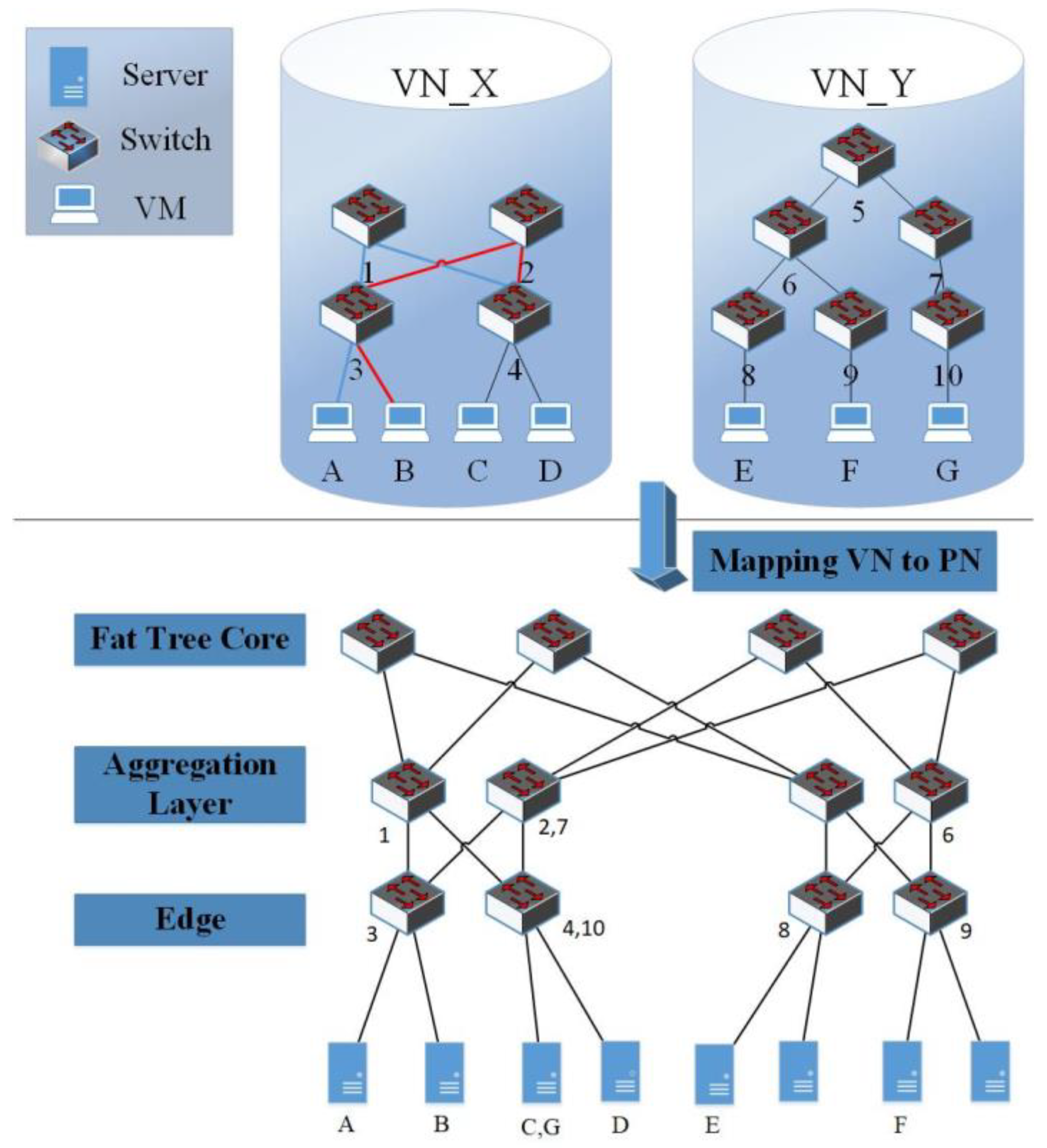
Virtually, in the cloud data center environment, VMs mapping of a VDC to a physical switch most likely overlaps another VDC. Therefore, to attain a global network topology, LLDP messages do not need to be sent by each VDC controller; instead, it can rely on another VDC, which has already requested the topology drastically reducing the workload on FlowVisor. In our work, we built a Green VDC Mapping Graph (GVMG) to represent inclusion advantages, a list to indicate VDCs with identical mappings supporting network topology request load balance. If the switches to which the VDC_B VMs map have those of VDC_A, the mapped switch of VDC_A demonstrates the maximum subset or has some switch, not in other subsets; thus, the paths between the mapped switches are identical. Afterward, a directed link is drawn from VDC_A to VDC_B illustrating the significance of this approach. In the fat tree module, if two mappings have to share same switches, then mapping links must be the same as any two adjacent switches exist on one link. Thus, we can ignore the paths between mapped switches to indicate an inclusive relationship. As shown in
Figure 6, the initializing of VDC_A VMs map to switch_1 and switch_2, the VMs of VDC_B map to switch_3 and switch_4, and VDC_C VMs map to switch_2 and switch_4 (
Figure 6A). No direct links among these VDCs exist due to no inclusive relationship. Now, we introduce VDC_D with its VMs mapped to switch_1, switch_2, switch_3, and switch_4. As the maximum subsets contain VDC_1, VDC_B, and VDC_C, we draw three corresponding direct links (
Figure 6B). Next, we introduce VDC_E with its VMs mapped to switch_1, switch_2, and switch_4; its maximum subsets contain VDC_1 and VDC_C, thus we add a direct link from VDC_A to VDC_E and another direct link from VDC_C to VDC_E. Meanwhile, as VDC_E has maximum subsets of VDC_D (
Figure 6C), we finally introduce VDC_F with identical mapping to VDC_E, and then the list of VDC_E added element VDC_F, where it can request network topology from VDC_E. When the mapping of VDC_G to coincide with VDC_E, it can request network topology from one randomized VDC in the list and be added to the list as a candidate for load balance (
Figure 6A). Accordingly, we propose the hierarchical state maintenance and query algorithm (Algorithm 1).
| Algorithm 1: VN_Topology_Request () |
| | Input: Mapping VDC), current Green VDC Mapping Graph (GVMG) |
| Output: Updated Green VDC Mapping Graph (GVMG). |
| Begin |
| 1 | vn_mappings getVN2PNMapping |
| 2 | start_nodes getMinDisjointSet(GVMG) |
| 3 | search_nodes getFilteredNodes(vn_mappings, start_nodes) |
| 4 | requested_node null |
| 5 | for each node in search_nodes do |
| 6 | node.visited true |
| 7 | requested_node DFS_visit(node) |
| 8 | end for |
| 9 | if requested_node != null then |
| 10 | selected_node requested_node.list.getRandomizedNode( ) |
| 11 | generated_node request_VN_topology(selected_node) |
| 12 | requested_node.list.add(generated_node) |
| 13 | Else |
| 14 | new_node do_LLDP_NetworkDiscovery( ) |
| 15 | GVMG.add(new_node) |
| 16 | end if |
| 17 | DFS_visit) |
| 18 | current_node |
| 19 | current_node.visited true |
| 20 | if vn_mappings.links == current_node.links and |
| 21 | vn_mappings.switches == current_node.switches then |
| 22 | requested_node current_node |
| 23 | Else |
| 24 | children_nodes current_node. children |
| 25 | for each node in children_nodes do |
| 26 | if node.visited != true then |
| 27 | DFS_visit(node) |
| 28 | end if |
| 29 | end for |
| 30 | end if |
| 31 | end DFS_visit |
Generally, the per-tenant network topology graph is always updated based on link events to observe the working state. If the underlying physical links go offline, the corresponding link event is triggered, and the relative network topology graphs will be accordingly adjusted. To allow the network topology graph update coherence, we adopt a bottom-up method linking events propagating in the direction as the GVMG specifies.
To determine the effectiveness of VN topology discovery optimization, we refer to the overall overlap ratio of VN to PN mappings. Thus, we can entirely refer to previous mapping results to lift the overlap ratio when a new VDC allocation task arrives. Alternatively, this problem can be solved by maintaining a centralized global PN topology. When a VDC executes its network discovery mechanism, the tailored VN topology responds, but a single-point-of-failure (SPOF) problem results, adding intense requests and highly stressing the tailoring PN topology to mapped switches. Our approach overcomes the two problems by making the SDN controller provision a platform as a service (PaaS), where tenants only need to upload to the corresponding application controllers.
4.3. VDC Cloud Datacenter Network Allocation
Portland provides a scalable second layer addressing, routing and forwarding for data center networks by observing the topology and baseline multi-rooted network fixed in the data center. Based on Portland, we can modify its forwarding and routing mechanism using sourcing routing and through the scalable fault-tolerant second layer (L2) domain of OpenFlow Portland Designs. The latter implements the Clos [
36] topology features in a multi-rooted framework of a traditional data center.
A combination of four-port switches into a 16-port multi-stage topology is illustrated in
Figure 7 Generally, by building a three-stage fat tree using
k port switches, a non-blocking communication can be supported between
k2/4 individual
k-port switches being used by
k3/4 end hosts [
39]. To this end,
k individual pods are obtained splitting the entire fat tree where these pods support non-blocking operations between the
k2/4 hosts mentioned previously. A similar approach is presented in [
39], where the authors used pods to represent entities supporting non-blocking networks.
4.4. Virtual Network Constraints
VDC allocation aims to map VN to the underlying fat tree physical network. We define a VN topology to not extend beyond three layers, as, in general, the majority of the VDC applications rely on an architecture formed in three layers: access, core, and aggregation. We use XML description to describe the GANA model, in which the depth must be ≤3. Moreover, we define additional constraints such that each VS is connected by a number of VMs given by the number of ports existing on the physical switch. In defining these constraints, we must agree with the number of real layers the underlying physical network (fat-tree type) can manage.
4.5. Switch-Centered Mapping
In our work, we proposed a heuristic switch centered based mapping mechanism for VN to PN to solve VDC allocation. The principal, built on a hierarchical architecture in a self-organizing approach, accelerates the mapping from VN to PN, using distributed VDC allocation. Such architecture employs task division, e.g.,
Global Leader (GL) and
Pod Allocation Managers (PAM), to allow efficient VDC allocation. Each PAM manages the local network separately, and the GL acts as a supervisor of the PAMs enforcing decomposition if necessary. The GL strategizes the VDC allocation delegating to the PAMs based on respective latency level, thus scheduling specialized VM agreeing with the tenant specifications. Moreover, another advantage represents exploiting PAM autonomy, in which a daemon responsible for path consolidation can achieve substantial network energy saving. To assure this architecture is self-organized, we design it on top of the Apache ZooKeeper [
40], a reliable and highly available coordination system including leader election algorithm among PAMs if the GL fails.
To check PAM resource availability, the latter regularly sends this information to the GL. Based on this, the index information decides if a PAM can handle VDC tasks or if it should distribute it among several PAMs stored in the GL. A tenant can request a VDC with 30,000 VMs, noting one pod contains 576 hosts and each of the houses 12 VMs, and a minimum of five pods is required to accommodate a VDC. This requires the GL to handle good resource management when determining the pods needed to fulfill a task. As illustrated in
Figure 8, two parts compose the index information. The first is the index for the edge layer, given by an increasing bandwidth interval [Bm, Bn]. The tuples correspond to <Switch, VM-number> where Switch corresponds to the number of VMs accommodated by one edge switch within the interval [Bm, Bn] and VM-number gives the sum of VMs that can be handled by a pod within this same interval. Secondly, the aggregation layer index is given, in the same format as the one used for the edge layer with the sole difference being the tuple <Switch, VM-number> now contains the same information but for one aggregation switch. In doing so, the assumption is that, only when both parts of this index information are fulfilled, will the allocation be assigned to a pod. The GL efficiently chooses between pods as ordered in increasing number of VMs they can handle, thus assuring reasonable VDC allocation. This simply makes sure one mapping from VN to VP exists based on an index information validation mechanism. Indeed, the efficiency of the fast allocation is improved, and if some pods are chosen, they can parallelly perform sub VDC allocation including mapping of VM and links through mapping centered switches. This sub VDC mapping finds the optimal choice selected from the possible mappings. However, it will vary with both sub VDC mapping mechanism used by the cloud service provider and per tenant strategy generated as the acting factor according to tenant intent. If no other choices are presented, we use a single mapping outcome.
4.6. Mapping Procedure
In this subsection, we discuss VN to PN mapping procedure as GL receives the request of VDC using the GANA model and the steps executed in Algorithm 2 are detailed.
| Algorithm 2: GANA-VDC_Allocation(VN) |
| | Input: Virtual Network (VN) |
| | Output: Allocation status (isAllocationFinished) |
| | Begin |
| 1 | Initialize indexlnfo |
| 2 | VNLevel = getVNLevel(VN) |
| 3 | taskToDo = [] |
| 4 | feedbacks = [] |
| 5 | if (VNLevel <= 2) then |
| 6 | taskToDo.add(VN.getTask()) |
| 7 | Else |
| 8 | subTasks = VN.decompose() |
| 9 | getL3Mappings(VN) |
| 10 | taskToDo.add(subTasks) |
| 11 | end if |
| 12 | Map<PAM, task> = GL.delegateToPAMs(taskToDo, indexlnfo) |
| 13 | update(indexInfo) |
| 14 | for <PAM, task> in Map<PAM, task> do |
| 15 | Thread.new( PAM.doSubAllocation(task)) |
| 16 | end for |
| 17 | while true do |
| 18 | feedbacks.add( receiveFeedbacks()) |
| 19 | if feedbacks.size() == taskToDo.size() then |
| 20 | if feedbacks.getResult() is success then |
| 21 | isAltocationFinished = true |
| 22 | Else |
| 23 | GL.rollback() |
| 24 | isAltocationFinished = false |
| 25 | end if |
| 26 | Break |
| 27 | end if |
| 28 | end while |
| 29 | return isAllocationFinished |
| 30 | doSubAllocation (task) |
| 31 | theMnppedEdgeSwitches = mapEdgeSwitch(VN) |
| 32 | getL2Mappings(VN) |
| 33 | scheduleVM2Hosts(theMappedEdgeSwitches) |
| 34 | getL1Mappings(VN) |
| 35 | end doSubAllocation |
Step 1. In accordance to the VN XML description, the GL determines the number of levels each VN possesses. Then, the VN structure is kept in the VN to PN map. In the meantime, the GL-calculated resource allocation refers to the index information. Only one pod should be allocated to perform the VN to PN mapping task in case less than two layers for the VN exist. Oppositely, the number of VN core switches decides the number of pods. From the moment the pods are discovered, we assume the links between the VN core switch and aggregation switch have been mapped. Lastly, the VN XML description of the selected pods is forwarded by the GL, sending only the part for which each pod is responsible to handle.
Step 2. An individual PAM receives the request from GL; it will sub-allocate simultaneously in accordance with local resource status, where the relation between the edge and the VN aggregation switches is ascertained, and eventually schedule to allocate VMs to servers with the abounded resource. Along with Step 1, all parts of VN are mapped. Through this step, a bipartite graph is constructed with the VESes in VN on the left side and the PESes on the right-side pod. We assume a PES poses a feasible candidate to a VES if the PES meets the requirement of VES of bandwidth and VM number, and all links between the PES and the mapped PASes should satisfy the condition the VN counterparts are not larger than the residual bandwidths of egress and ingress type, respectively. An edge is drawn between the VES and the PES if the PES is considered a valid candidate. To obtain a match, the min-cost network flow is then applied [
41]. To the right of the PESes, a dst node is added while, to the left side of the VESes, a source node is added. Between each of these pairs, edges are also added. To define the weight a certain edge needs to carry, and we look at the bandwidth of the corresponding PES, indicated by the sum of both upward and downward link bandwidth. This bidirectional question of matching then becomes a question of defining the minimum cost flow between
dst and
scr where the capacity
m is determined by the amount of VESes. According to our VN to PN mapping methodology, we can find at least one match. Better network utilization can be obtained by properly assigning the weights because PEG with a higher residual bandwidth is favored, thus balancing the mapping quality by better utilizing it. When scheduling VMs to servers in the scope of PES, we presume no two VMs will be scheduled to the same servers. Thus, a bipartite graph between VMs and servers will be created. Similarly, with this methodology, a VES to PES mapping achieves high network utilization.
Step 3. Every PAM participating acknowledges the result of its GL sub-allocation. Only when all PAMs respond will the allocation be considered completed. The GL instructs all the other participants to perform a rollback in case one participant fails to inform the GL of its response representing a failure. In the process of VDC allocation, we use three-phase balanced mapping measures. In the first phase, we map core switches and aggregation switches of VN to those of PN, hence the links between the core layer and aggregation layer remain fixed. In the second phase, we select the appropriate edge switches of PN to map to the VN. Thus, the connections between the edge layer and the aggregation layer remain fixed. Lastly, in the third phase, we schedule the corresponding VMs to the servers in the mapped switches. Eventually, the links between the edge layer and the servers remain fixed. With these three phases, we complete the overall VN to PN mapping procedure. Note that we consider the factor of even VDC allocation in all the mapping phases. Within the first phase, we sort the pods in ascending order in accordance with the VMs that can be accommodated. The pods are selected in a greedy approach. Through Phases 2 and 3, we abstract the corresponding mappings into the min-cost network flow problem. By making every partial mapping even, we achieve overall fair balanced VDC allocation, achieving higher network utilization.
5. Experiments and Evaluation
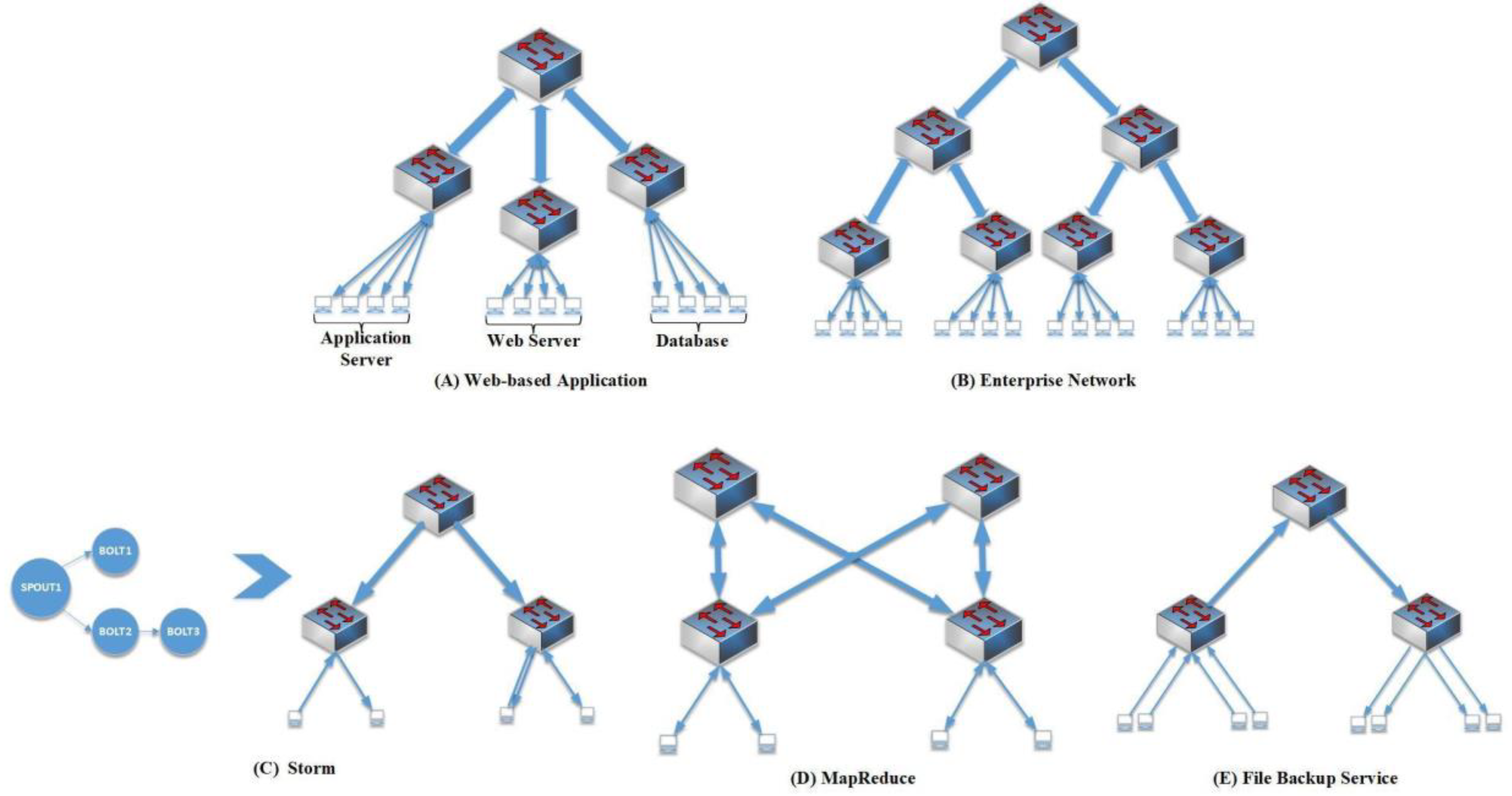
In our experiment, we evaluated the performance of our VDC allocation mechanism, conducting experiments on Dawning server eight quad-core AMD 800 MHZ CPU and 32G RAM. In this experiment, a simulator with three-level fat-tree topology with 48 port 10Gig Ethernet commodity switches was used. In this simulation, there were 27,648 physical nodes and 24 VMs accommodated per host, resulting in 663,552 virtual machines. All applications requiring guaranteed bandwidth were analyzed using statistics. Five possible outcomes of this analysis allowed us to categorize them into typical scenarios for applications. Note the assumption were made to choose the most suitable VN topology for each of these applications in an empirical fashion. These were chosen as templates to help mimic and create VN topology.
Web-based application
(Figure 9A): Multi-tier application forms the majority of the web-based applications [
42]. Typically, three tiers exist: front-end web-based server, medium application server, and the back-end database. Bandwidth guarantees favor the middle-to-backend and frontend-to-middle to assure a predictable performance while servicing web services tenants.
Enterprise networks
(Figure 9B): Companies purchase cloud services to automate typical office work. The majority of middle-size companies have hundreds of employees divided into departments; therefore, thousands of hosts are needed. Generally, an enterprise network with oversubscription will benefit from using a three-layer model.
Storm (
Figure 9C): The application for real-time data analytics. Storm [
43] is used for ML on the web with a non-interrupted calculation of data streams. These kinds of applications are composed of two Java thread implemented parts: “bolts”, which represents both a mapper and reducer; and “spouts”, analog to the mappers used in MapReduce [
44]. The traffic among components is considered exceedingly directional.
MapReduce (
Figure 9D): Many infrastructure services demand non-blocking network services such as MapReduce [
44]. Intermediate files need to be fetched from various servers when performing the Reduce operation phase in the MapReduce mechanism. The traffic forms an all-to-all communication pattern the Reduce workers generate, thus highlighting the need for the specific network topology a fat-free topology offers.
File backup service (
Figure 9E): The characteristic of this service mostly reflects downward traffic.
Table 2 describes the proportion accounting for each application in our experiments. We did not consider the CPU intensive applications, as we assume they did not impose a noticeable impact on networking. Synthetic VDC application types were generated, where the ratio occupied by each application decided the optimal way to distribute it. Furthermore, the size of the VDC was randomized, and the weight for the VN topology was assigned. We chose different ranges and empirical estimates based on variance with the chosen template.
The network utilization, given by (network_util), demonstrates how the VDCs were divided by the total link capacity, while (server_util), i.e., the server bandwidth utilization, corresponds to the same bandwidth but distributed via server link capacity. Finally, pod bandwidth utilization, (pod_ util), follows the same definition but with the pod capacity as the dividing factor. A series of VDCs generated at random was added into the created networks, where only when the sum of rejected VDC allocations goes beyond the threshold of at least 20 times was the algorithm stopped. The results we report represent mean values for 100 measures. Overall, 70,855 allocations (99.86%) were successful out of 70,957 allocations.
Even Allocation: In
Figure 10, the plots of (
pod_util) have similar trends during all of the VDC allocations in any percentage of the number of VDC allocations, and the (
pod_util) of most of the pods remain close. Thus, the network resource was evenly allocated among pods. Through three-phase balanced mapping, our algorithm ensured the fair distribution of network utilization during VDC allocation.
High Network Utilization: We collect statistics of network utilization in
Figure 10a. The horizontal axis represents the percentage of the number of the allocated VDCs. The vertical axis indicates network utilization.
Figure 10b shows the resources were primarily utilized with our proposed algorithm for VDC allocation: 94% for (
server_util), and 87% for (
pod_util) of all the pods on average, and 61% for (
network_util). When confronted with the first VDC allocation failure, (
server_util) was close to 82%. Because most of the VN of VDCs comprise two layers, they are supposed to be mapped to the corresponding aggregation layer and edge layer and in the underlying physical network the ratio between the connections between the three layers equals 1:1:1; thus, the bisection bandwidth between the aggregation and the core layers was not used entirely when no bandwidth remains available to the servers. In our experiment, only the enterprise network in the application types occupied three layers. However, its proportion remained low, thus an upper limit of network utilization was set at 65.66% in principle.
Efficient and Scalable Allocation: To facilitate analyzing the VDC allocation efficiency, the intervals are defined based on the ratios of the volumes of VDC allocations when cloud data center approached heavy loads in
Figure 11. Here, we set the interval at 20%. All VDC allocations are points in this figure to depict the allocation times together. Two clear black lines stand out where the lower one refers to the VDC applications with two-layer networks, and the upper one agrees with the data from three-layer networks. A linear fit processing in
Figure 11a shows the scalability of the algorithm to perform allocation through these points, as the allocation time scaled almost linearly with the increasing number of VDC. In
Figure 11b, the allocation time almost keeps stable with the increasing VNC number, and the moving average stays close to the lower line since most of applications are of two-layer network types. Because most of the applications engender a two-layer network type, the linear fit line usually agreed with the lower black line. This agreement worsened slightly when the number of VDC allocations increased. While the VDC allocations progressed, the network resources were affected negatively when they tried to determine which PAM to use for a VDC allocation based on the info regarding the global index. Usually, the time required for a VDC allocation ranged 100
–600 ms. However, for intervals from 80% to 100%, sometimes data points rose to as high as 2 s. This was rationalized as some applications containing three-layer networks required a more thorough search of the index information. Indeed, in the case of a deficient network, at times, the whole index information might need to be traversed to detect a proper PAM. We can finally conclude, based on this analysis, the algorithm efficiently and adequately allocates the VDC.
Comparison: As server network utilization reached 80% of its capacity, we tested eight VDCs allocations with 800 VMs to examine VDC algorithm efficiency. In comparison to SecondNet [
13] with the same physical network scale in
Figure 12, for thousands of VMs in the VDC in a fat-tree topology, SecondNet performed allocation in 20–90 s, while GANA-VDC only took 0.41–0.48 s. The results show GANA-VDC allocation time cost was far less.
Mappings Duplication: In our experiments, more than 70,000 active mapping sets consisted of the mapped physical switches. Statistically, we analyzed the number of VDC allocations with the same mapping sets, about 40,550; thus, we computed the duplication degree of the VDC allocations, about 42.49% on average. With our proposed VDC allocation algorithm, we did not take this factor into consideration, and, to some extent, the results prove our VN topology discovery optimization to be more beneficial.
6. Discussion
For us to achieve desirable application-aware networking, we implemented and extended techniques proposed from previous works. FlowVisor [
10] and FlowN [
45] were used to provide a network virtualization layer to allow multiple isolated logical networks each with potentially different addressing and forwarding mechanisms to share the same physical infrastructure [
46]. We extended them by adding an interceptor in VN responsible for source routing in a scalable large 2-layer network. For the provisioning of fine-grained traffic control, we employed the original OpenFlow QoS pattern by giving a VDC limited flowtable. We also optimized the topology discovery measure in large-scale datacenters containing many VDCs, combining inherently sending and receiving LLDP messages resorting to other VDCs. Hence, we effectively balanced the load from the per-tenant topology discovery.
Tenants can build arbitrary VN topology architecture just as they used to construct individual networks. We propose the GANA model, describing VDC using its resource demands, in addition to VN and VMs. Contrary to other models, it has superior advantages such as unprecedentedly supporting multipath VN, and self-defined link bandwidth more precisely benefits pay-as-you-go business model in cloud computing. Based on the GANA model, we scheme a novel switch centered VN to PN mapping algorithm. Contrary to previous heuristic VN to PN mapping algorithms, it can be deemed as parallel and coupled with optimization to dedicate fat tree topology, thus resulting in remarkable speed.
While the current technology seeks to resolve the challenge of Virtual network embedding as the ultimate solution, different disciplinaries are being developed to improve the services. This was documented by Andreas et al., who developed an interest in the future work on distributed VNE. This is in a bid to resolve the Intra-InP VNE challenge. While the format resolves the challenge of a centralized approach, it faces the challenge of being optimal in resource usage.
Similar to previous works in this research field, we did not consider high availability or low latency when allocating the VDCs executed, even though the VMs of each VDC scheduled to various pods can augment high availability. Nevertheless, we consider high availability and low latency as allocation strategies, and the hierarchical architecture designed for VN to PN mapping can support tenant selecting different allocation strategies. We maintain these possibilities to refine our system scheme for future work.

 ,
, 


