Figure 1.
PLIS-based DSLIFFT algorithm.
Figure 1.
PLIS-based DSLIFFT algorithm.
Figure 2.
PLIS-based DSLIFFT algorithm with 4MSCW.
Figure 2.
PLIS-based DSLIFFT algorithm with 4MSCW.
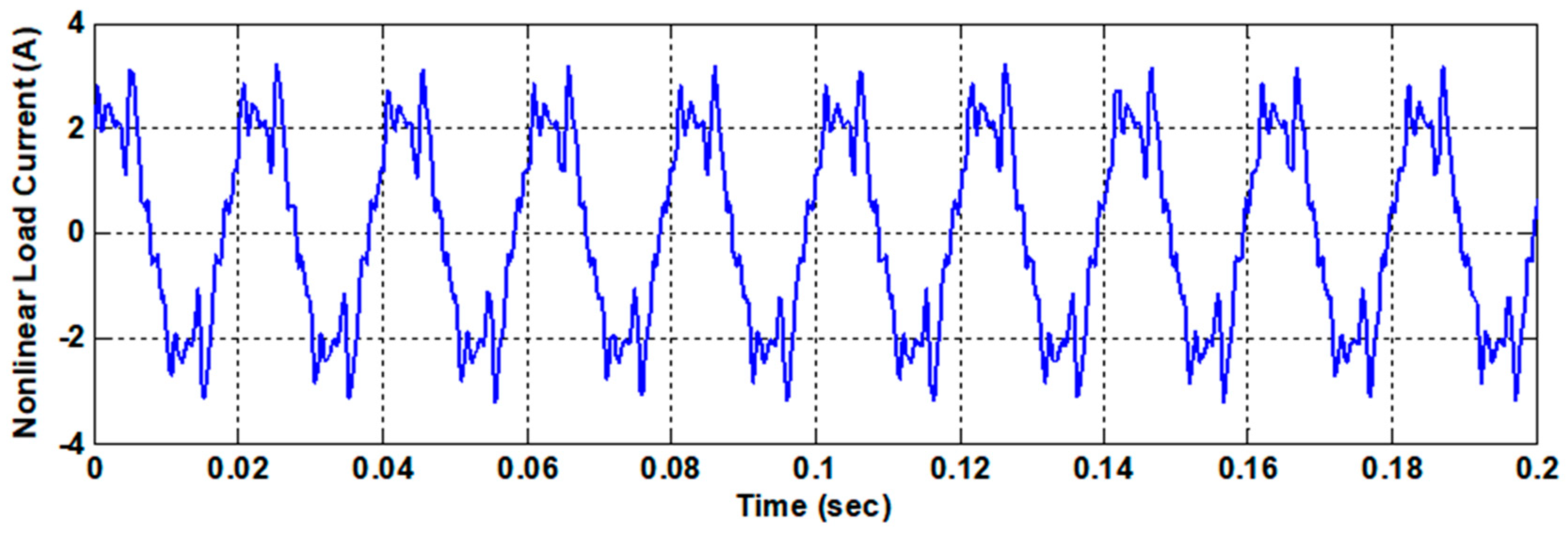
Figure 3.
Benchmark harmonic test signal.
Figure 3.
Benchmark harmonic test signal.
Figure 4.
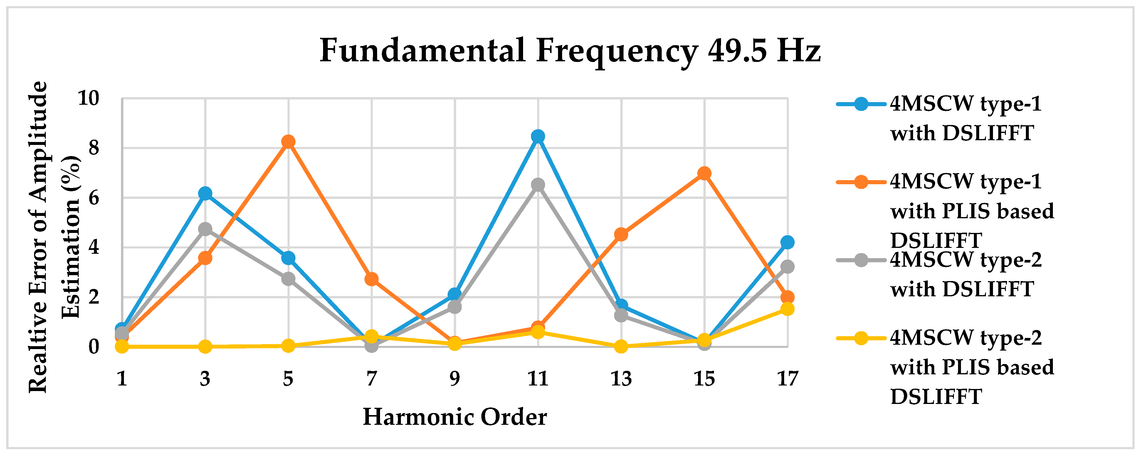
Percentage relative errors variation of amplitude estimation to the harmonic order with proposed PLIS-based DSLIFFT and conventional DSLIFFT using 4MSCW type-1 and type-2 at the frequency is 49.5 Hz.
Figure 4.
Percentage relative errors variation of amplitude estimation to the harmonic order with proposed PLIS-based DSLIFFT and conventional DSLIFFT using 4MSCW type-1 and type-2 at the frequency is 49.5 Hz.
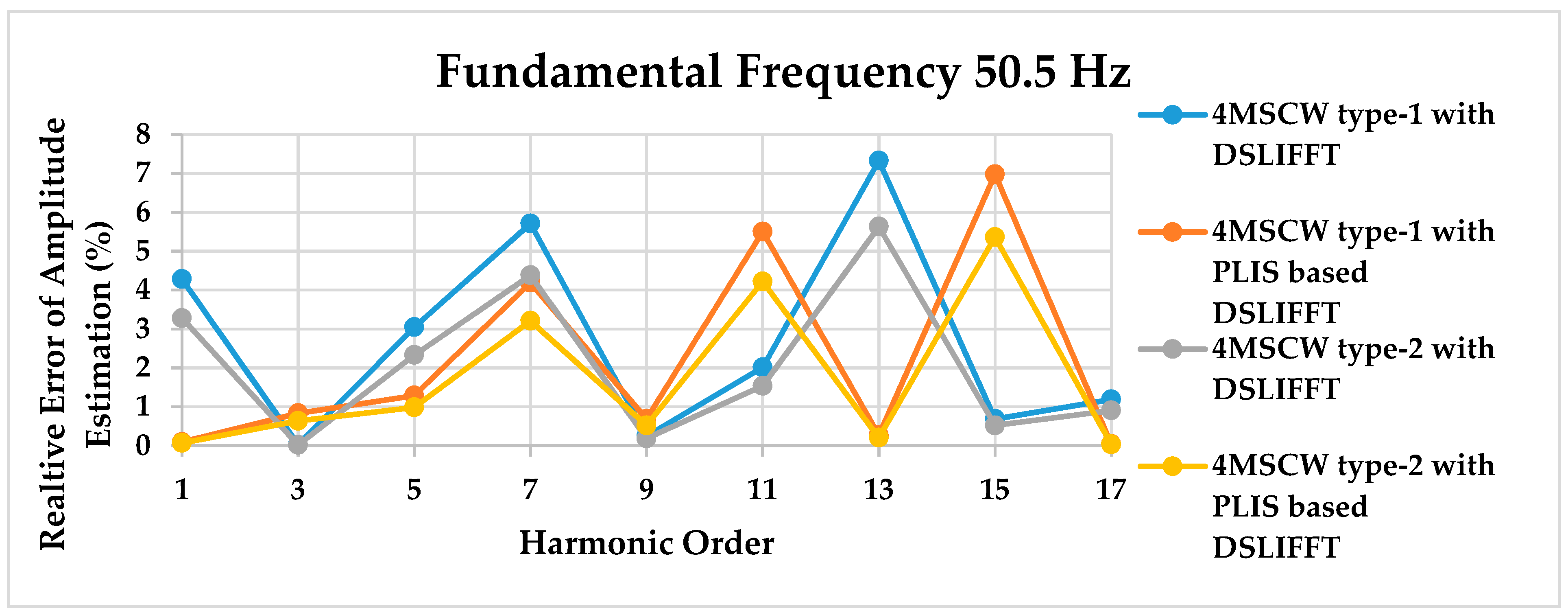
Figure 5.
Percentage relative errors variation of amplitude estimation to the harmonic order with proposed PLIS-based DSLIFFT and conventional DSLIFFT using 4MSCW type-1 and type-2 at the frequency 50.5 Hz.
Figure 5.
Percentage relative errors variation of amplitude estimation to the harmonic order with proposed PLIS-based DSLIFFT and conventional DSLIFFT using 4MSCW type-1 and type-2 at the frequency 50.5 Hz.
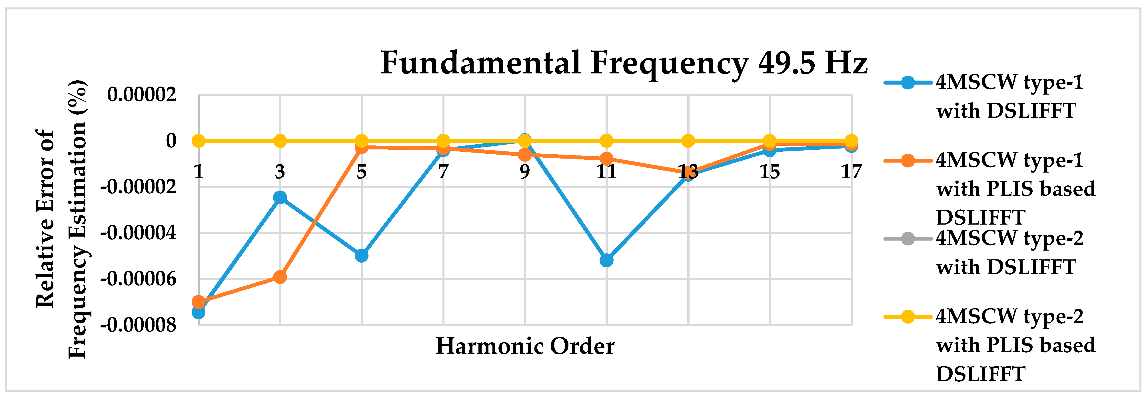
Figure 6.
Percentage relative errors variation of frequency estimation to the harmonic order with proposed PLIS-based DSLIFFT and conventional DSLIFFT using 4MSCW type-1 and type-2 at the frequency 49.5 Hz.
Figure 6.
Percentage relative errors variation of frequency estimation to the harmonic order with proposed PLIS-based DSLIFFT and conventional DSLIFFT using 4MSCW type-1 and type-2 at the frequency 49.5 Hz.
Figure 7.
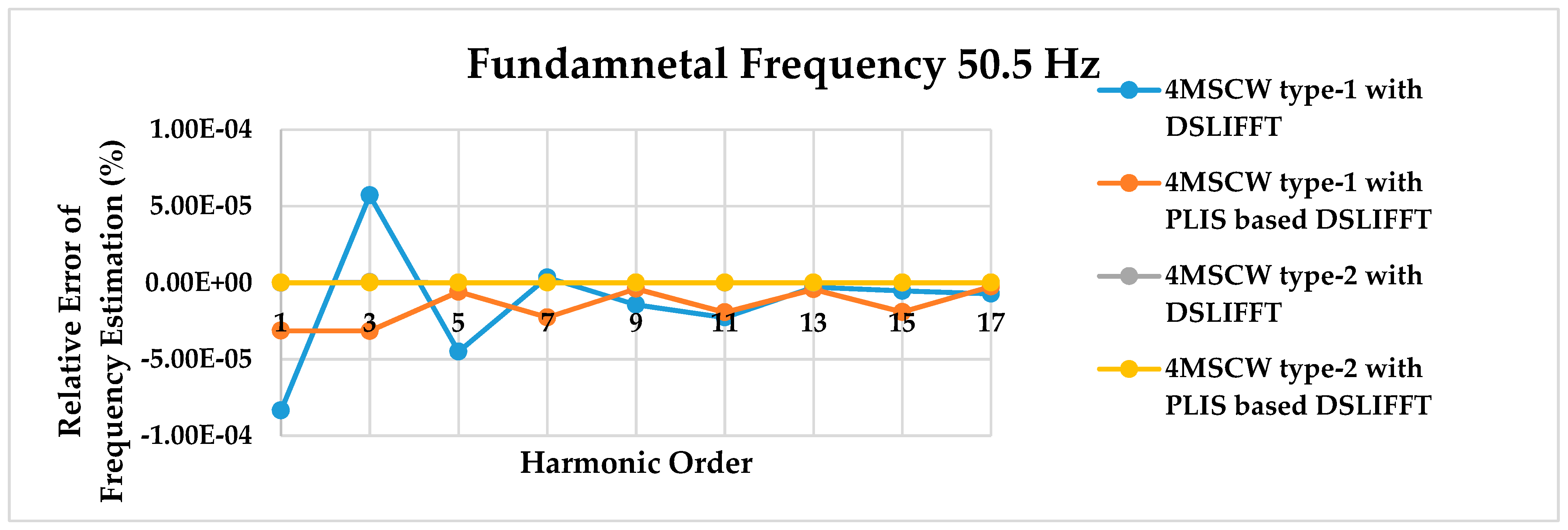
Percentage relative errors variation of frequency estimation to the harmonic order with proposed PLIS-based DSLIFFT and conventional DSLIFFT using 4MSCW type-1 and type-2 at the frequency 50.5 Hz.
Figure 7.
Percentage relative errors variation of frequency estimation to the harmonic order with proposed PLIS-based DSLIFFT and conventional DSLIFFT using 4MSCW type-1 and type-2 at the frequency 50.5 Hz.
Figure 8.
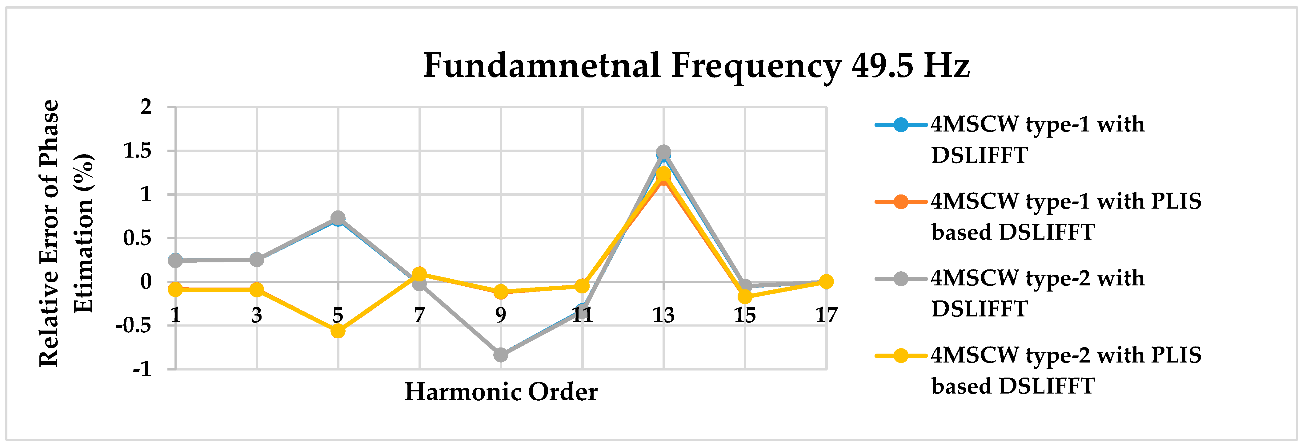
Percentage relative errors variation of phase estimation to the harmonic order with proposed PLIS-based DSLIFFT and conventional DSLIFFT using 4MSCW type-1 and type-2 at the frequency 49.5 Hz.
Figure 8.
Percentage relative errors variation of phase estimation to the harmonic order with proposed PLIS-based DSLIFFT and conventional DSLIFFT using 4MSCW type-1 and type-2 at the frequency 49.5 Hz.
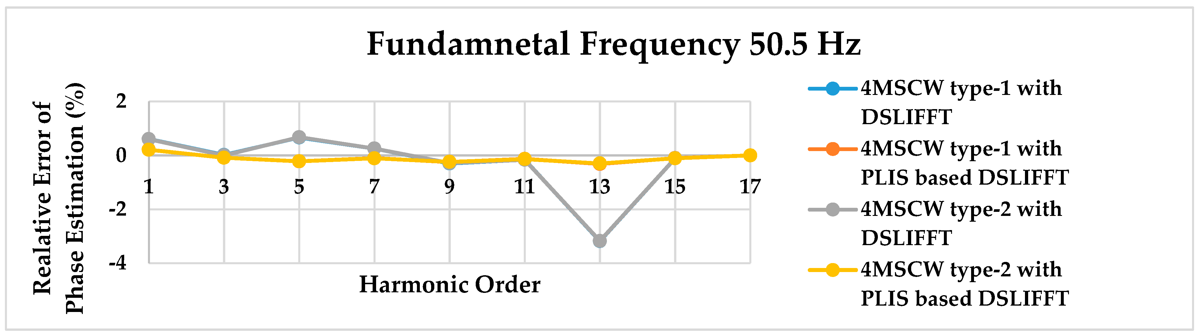
Figure 9.
Percentage relative errors variation of phase estimation to the harmonic order with proposed PLIS-based DSLIFFT and conventional DSLIFFT using 4MSCW type-1 and type-2 at the frequency is 50.5 Hz.
Figure 9.
Percentage relative errors variation of phase estimation to the harmonic order with proposed PLIS-based DSLIFFT and conventional DSLIFFT using 4MSCW type-1 and type-2 at the frequency is 50.5 Hz.
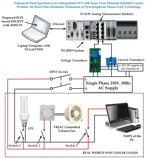
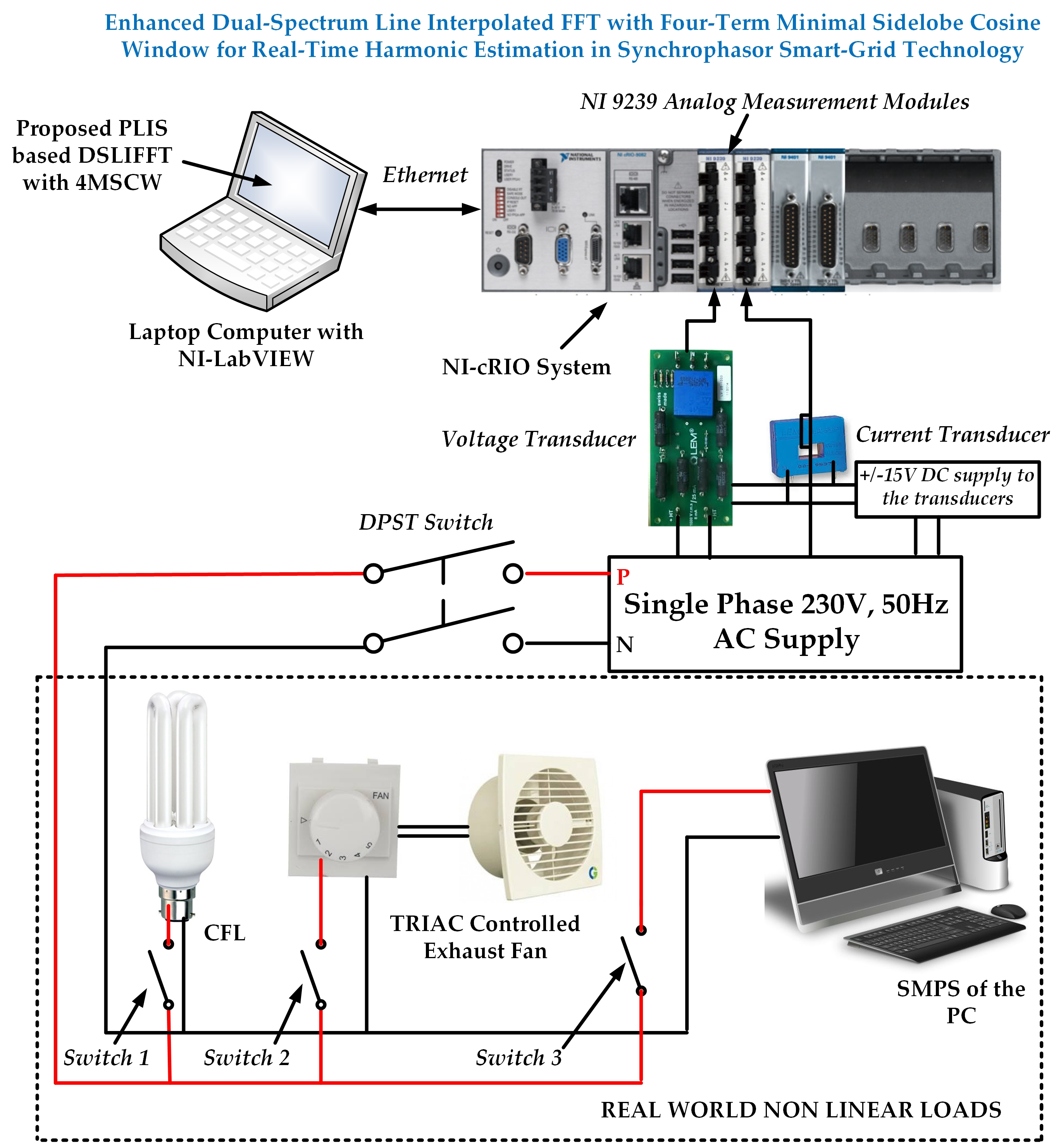
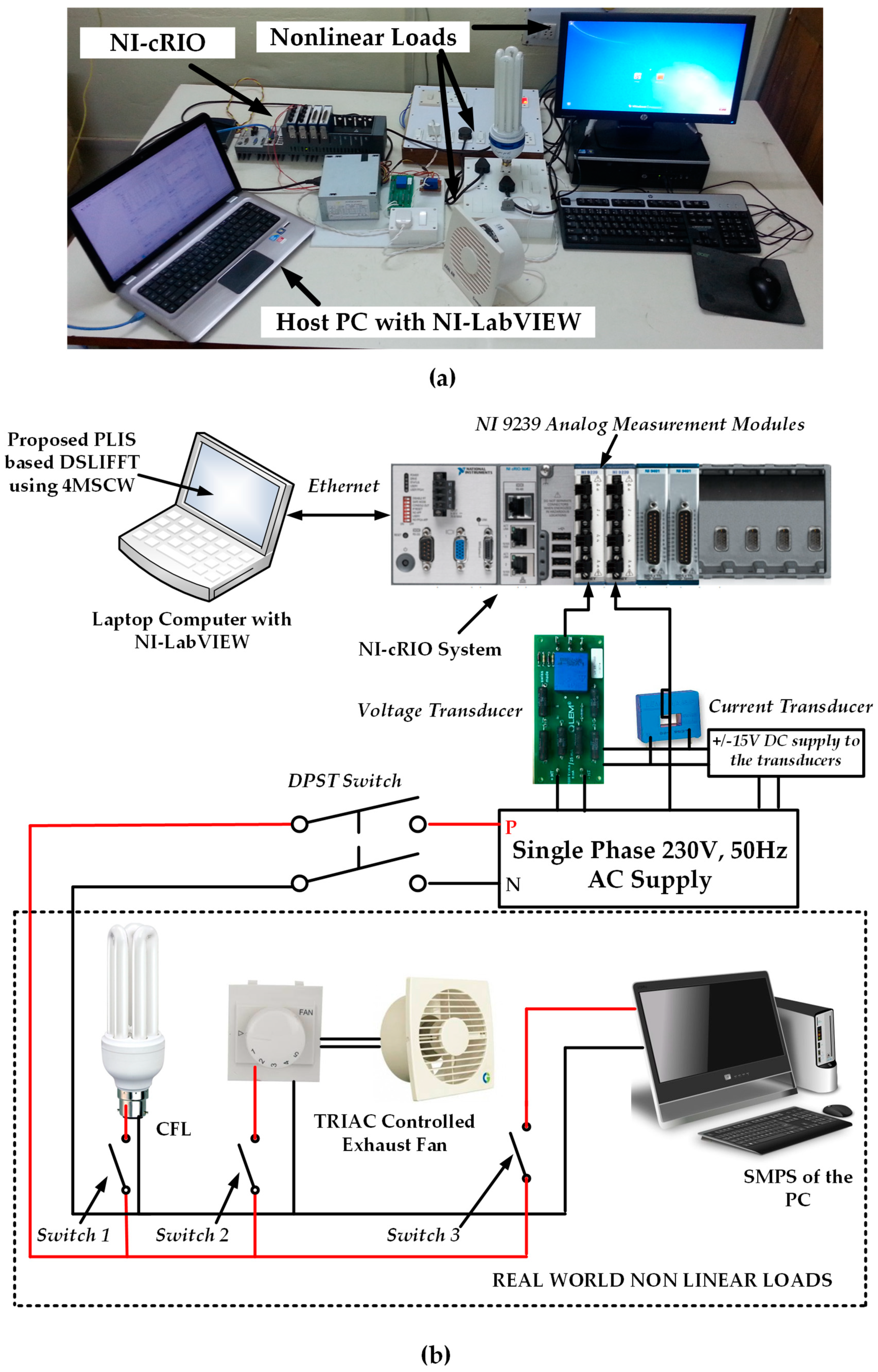
Figure 10.
NI-cRIO-based experimental setup. (a) Lab setup; (b) Setup drawing.
Figure 10.
NI-cRIO-based experimental setup. (a) Lab setup; (b) Setup drawing.
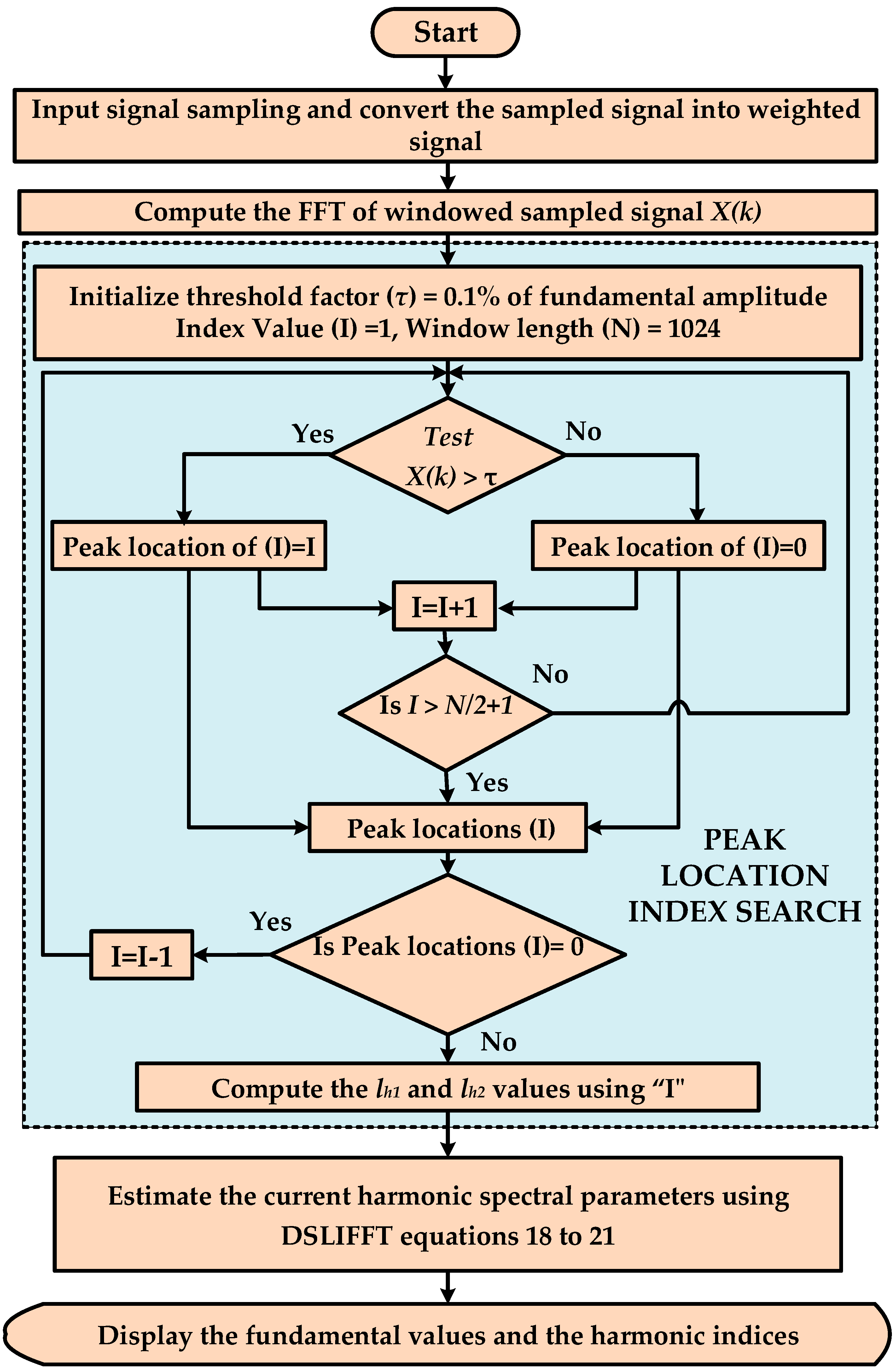
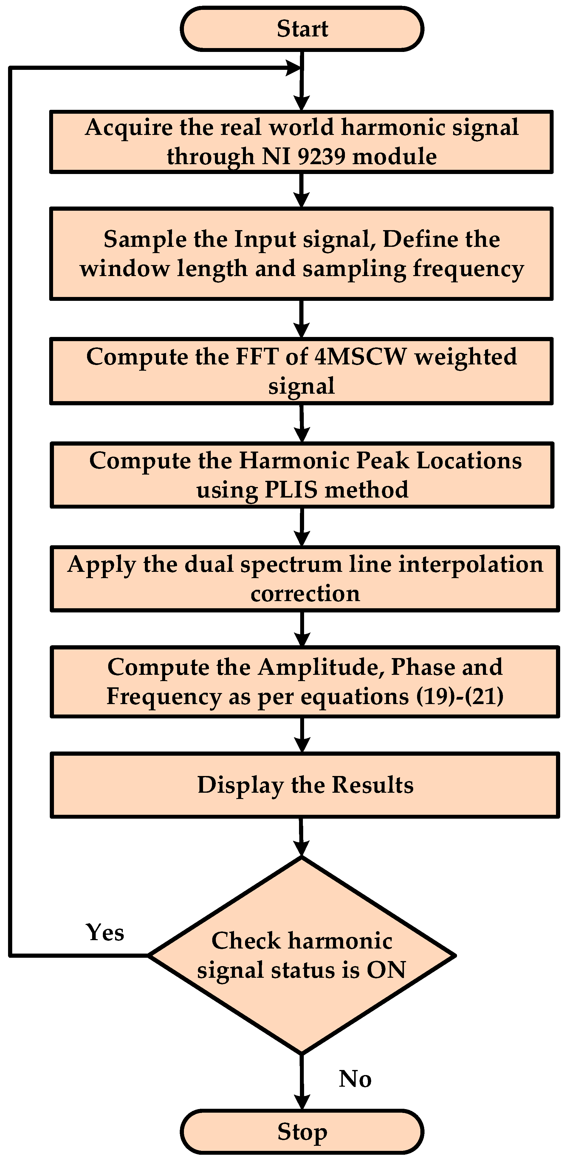
Figure 11.
Flowchart of the proposed PLIS based DSLIFFT Algorithm with 4MSCW in RT estimation.
Figure 11.
Flowchart of the proposed PLIS based DSLIFFT Algorithm with 4MSCW in RT estimation.
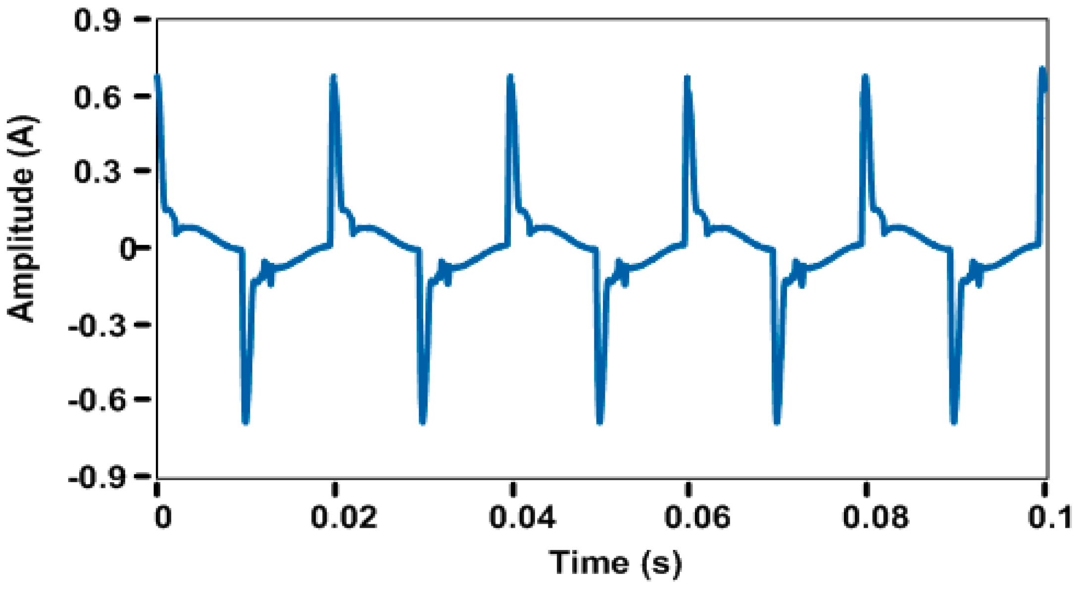
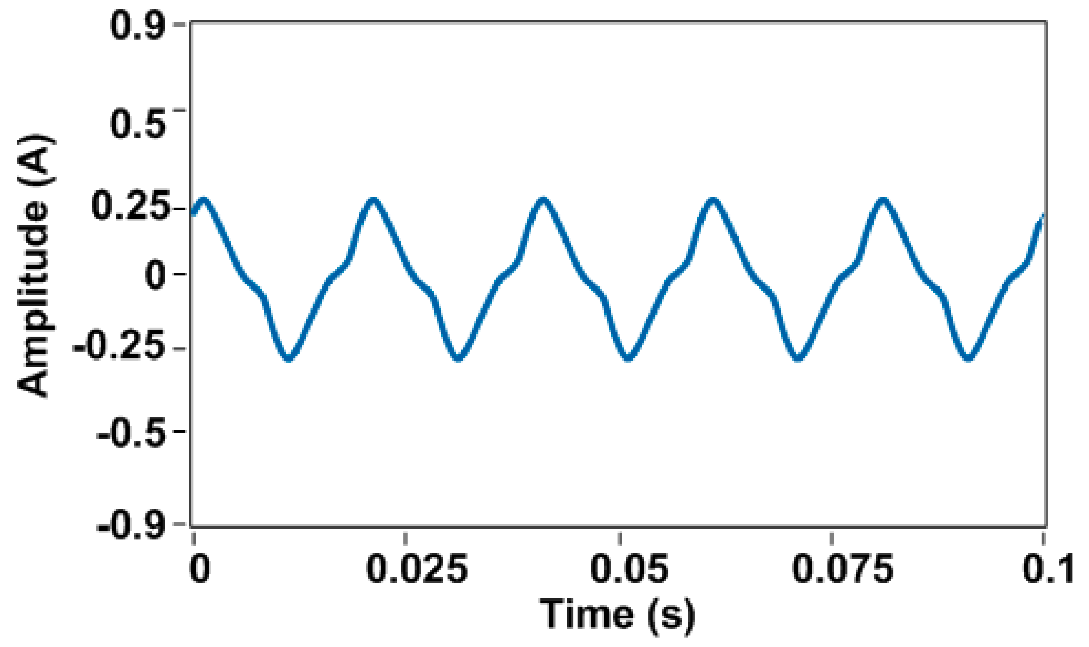
Figure 12.
CFL and Computer with UPS load current waveform.
Figure 12.
CFL and Computer with UPS load current waveform.
Figure 13.
TRIAC controlled Ventilating Electric Fan load current waveform.
Figure 13.
TRIAC controlled Ventilating Electric Fan load current waveform.
Table 1.
4MSCW Coefficients and Properties.
Table 1.
4MSCW Coefficients and Properties.
| Window Type | Window Coefficients | Main Lobe Width | Peak Sidelobe Level (dB) | Sidelobe Roll-off Rate (dB/oct) |
|---|
| a0 | a1 | a2 | a3 |
|---|
| 4MSCW type-1 | 0.355768 | 0.487396 | 0.144232 | 0.012604 | 4Hπ/N | −93 | 18 |
| 4MSCW type-2 | 0.3125 | 0.46875 | 0.1875 | 0.03125 | 4Hπ/N | −61 | 42 |
Table 2.
4MSCW Polynomial Coefficients.
Table 2.
4MSCW Polynomial Coefficients.
| Window Type | a0 | a1 | a2 | a3 | a4 |
|---|
| 4MSCW type-1 | 2.6645 | - | 0.2806 | - | 0.1313 |
| 4MSCW type-2 | 3.5 | - | - | - | - |
Table 3.
Simulated harmonic test signal information.
Table 3.
Simulated harmonic test signal information.
| Parameters | Harmonic Orders (Fundamental Frequency = 49.5 Hz and 50.5 Hz) |
|---|
| 1 | 3 | 5 | 7 | 9 | 11 | 13 | 15 | 17 |
|---|
| Amplitude (A) | 2.5 | 0.4 | 0.35 | 0.3 | 0.25 | 0.2 | 0.2 | 0.15 | 0.2 |
| Phase (deg) | 40 | 115 | −30 | 110 | −20 | 100 | −10 | −90 | 0 |
| Frequency (Hz) | 49.5 | 148.5 | 247.5 | 346.5 | 445.5 | 544.5 | 643.5 | 742.5 | 841.5 |
| 50.5 | 151.5 | 252.5 | 353.5 | 454.5 | 555.5 | 656.5 | 757.5 | 858.5 |
Table 4.
Amplitude estimation comparison using 4MSCW type-1 with DSLIFFT and proposed PLIS-based DSLIFFT, when the fundamental frequency = 49.5 Hz.
Table 4.
Amplitude estimation comparison using 4MSCW type-1 with DSLIFFT and proposed PLIS-based DSLIFFT, when the fundamental frequency = 49.5 Hz.
| Harmonic Order (h) | Amplitude (A) Estimation Using 4MSCW Type-1 with DSLIFFT [12,13,14,15,16,17,18] | Amplitude (A) Estimation Using 4MSCW Type-1 with Proposed PLIS-Based DSLIFFT | The Relative Error of Amplitude Estimation (%) |
|---|
| 4MSCW Type-1 with DSLIFFT | 4MSCW Type-1 with Proposed PLIS-Based DSLIFFT |
|---|
| 1 | 2.4824 | 2.4899 | 0.7028 | 0.4020 |
| 3 | 0.3753 | 0.3857 | 6.1643 | 3.5653 |
| 5 | 0.3375 | 0.3211 | 3.5652 | 8.2501 |
| 7 | 0.2998 | 0.2918 | 0.0502 | 2.7204 |
| 9 | 0.2448 | 0.2496 | 2.0958 | 0.1525 |
| 11 | 0.1831 | 0.1985 | 8.4625 | 0.7695 |
| 13 | 0.1967 | 0.1910 | 1.6485 | 4.5175 |
| 15 | 0.1498 | 0.1395 | 0.1524 | 6.9757 |
| 17 | 0.1916 | 0.1960 | 4.2013 | 1.9859 |
Table 5.
Amplitude estimation comparison using 4MSCW type-2 with DSLIFFT and proposed PLIS-based DSLIFFT, when the fundamental frequency = 49.5 Hz.
Table 5.
Amplitude estimation comparison using 4MSCW type-2 with DSLIFFT and proposed PLIS-based DSLIFFT, when the fundamental frequency = 49.5 Hz.
| Harmonic Order (h) | Amplitude (A) Estimation Using 4MSCW Type-2 with DSLIFFT [12,13,14,15,16,17,18] | Amplitude (A) Estimation Using 4MSCW Type-2 with Proposed PLIS-Based DSLIFFT | The Relative Error of Amplitude Estimation (%) |
|---|
| 4MSCW Type-2 with DSLIFFT | 4MSCW Type-2 with Proposed PLIS-Based DSLIFFT |
|---|
| 1 | 2.4866 | 2.4998 | 0.5361 | 0.0071 |
| 3 | 0.3811 | 0.3999 | 4.7318 | 0.0035 |
| 5 | 0.3405 | 0.3498 | 2.7285 | 0.0371 |
| 7 | 0.2999 | 0.2988 | 0.0384 | 0.4133 |
| 9 | 0.2460 | 0.2497 | 1.6013 | 0.1162 |
| 11 | 0.1870 | 0.1988 | 6.5141 | 0.5870 |
| 13 | 0.1975 | 0.1999 | 1.2588 | 0.0111 |
| 15 | 0.1498 | 0.1496 | 0.1162 | 0.2658 |
| 17 | 0.1936 | 0.1970 | 3.2176 | 1.5171 |
Table 6.
Amplitude estimation comparison using 4MSCW type-1 with DSLIFFT and proposed PLIS-based DSLIFFT, when the fundamental frequency = 50.5 Hz.
Table 6.
Amplitude estimation comparison using 4MSCW type-1 with DSLIFFT and proposed PLIS-based DSLIFFT, when the fundamental frequency = 50.5 Hz.
| Harmonic Order (h) | Amplitude (A) Estimation Using 4MSCW Type-1 with DSLIFFT [12,13,14,15,16,17,18] | Amplitude (A) Estimation Using 4MSCW Type-1 with Proposed PLIS-Based DSLIFFT | The Relative Error of Amplitude Estimation (%) |
|---|
| 4MSCW Type-1 with DSLIFFT | 4MSCW Type-1 with Proposed PLIS-Based DSLIFFT |
|---|
| 1 | 2.3930 | 2.4977 | 4.2795 | 0.0931 |
| 3 | 0.3999 | 0.3967 | 0.0266 | 0.8342 |
| 5 | 0.3393 | 0.3455 | 3.0453 | 1.2898 |
| 7 | 0.2829 | 0.2874 | 5.7078 | 4.1883 |
| 9 | 0.2494 | 0.2483 | 0.2479 | 0.6866 |
| 11 | 0.1960 | 0.1890 | 2.0134 | 5.5007 |
| 13 | 0.1854 | 0.1995 | 7.3230 | 0.2709 |
| 15 | 0.1490 | 0.1395 | 0.6867 | 6.9756 |
| 17 | 0.1976 | 0.1999 | 1.1892 | 0.0447 |
Table 7.
Amplitude estimation comparison using 4MSCW type-2 with DSLIFFT and proposed PLIS-based DSLIFFT, when the fundamental frequency = 50.5 Hz.
Table 7.
Amplitude estimation comparison using 4MSCW type-2 with DSLIFFT and proposed PLIS-based DSLIFFT, when the fundamental frequency = 50.5 Hz.
| Harmonic Order (h) | Amplitude (A) Estimation Using 4MSCW Type-2 with DSLIFFT [12,13,14,15,16,17,18] | Amplitude (A) Estimation Using 4MSCW Type-2 with Proposed PLIS-Based DSLIFFT | The Relative Error of Amplitude Estimation (%) |
|---|
| 4MSCW Type-2 with DSLIFFT | 4MSCW Type-2 with Proposed PLIS-Based DSLIFFT |
|---|
| 1 | 2.4181 | 2.4982 | 3.2777 | 0.0709 |
| 3 | 0.3999 | 0.3975 | 0.0210 | 0.6367 |
| 5 | 0.3418 | 0.3466 | 2.3292 | 0.9845 |
| 7 | 0.2869 | 0.2904 | 4.3793 | 3.2077 |
| 9 | 0.2495 | 0.2487 | 0.1888 | 0.5237 |
| 11 | 0.1969 | 0.1916 | 1.5380 | 4.2192 |
| 13 | 0.1887 | 0.1996 | 5.6291 | 0.2065 |
| 15 | 0.1492 | 0.1420 | 0.5237 | 5.3599 |
| 17 | 0.1982 | 0.1999 | 0.9077 | 0.0341 |
Table 8.
Frequency estimation comparison using 4MSCW type-1 with DSLIFFT and proposed PLIS-based DSLIFFT, when the fundamental frequency = 49.5 Hz.
Table 8.
Frequency estimation comparison using 4MSCW type-1 with DSLIFFT and proposed PLIS-based DSLIFFT, when the fundamental frequency = 49.5 Hz.
| Harmonic Order (h) | Frequency (Hz) Estimation Using 4MSCW Type-1 with DSLIFFT [12,13,14,15,16,17,18] | Frequency (Hz) Estimation Using 4MSCW Type-1 with Proposed PLIS-Based DSLIFFT | The Relative Error of Frequency Estimation (%) |
|---|
| 4MSCW Type-1 with DSLIFFT | 4MSCW Type-1 with Proposed PLIS-Based DSLIFFT |
|---|
| 1 | 49.5000346 | 49.50003683 | −7.4406 × 10−05 | −6.9938 × 10−05 |
| 3 | 148.5000878 | 148.5000365 | −2.4595 × 10−05 | −5.9110 × 10−05 |
| 5 | 247.5000069 | 247.5001234 | −4.9840 × 10−05 | −2.7740 × 10−06 |
| 7 | 346.5000111 | 346.5000139 | −4.0007 × 10−06 | −3.2111 × 10−06 |
| 9 | 445.5000269 | 445.4999988 | 2.7295 × 10−07 | −6.0283 × 10−06 |
| 11 | 544.5000422 | 544.5002823 | −5.1850 × 10⁻⁵ | −7.7484 × 10−06 |
| 13 | 643.5000888 | 643.5000947 | −1.4715 × 10−05 | −1.3799 × 10−05 |
| 15 | 742.5000096 | 742.5000303 | −4.0779 × 10−06 | −1.2987 × 10−06 |
| 17 | 841.5000116 | 841.5000183 | −2.1798 × 10−06 | −1.3728 × 10−06 |
Table 9.
Frequency estimation comparison using 4MSCW type-2 with DSLIFFT and proposed PLIS-based DSLIFFT, when the fundamental frequency = 49.5 Hz.
Table 9.
Frequency estimation comparison using 4MSCW type-2 with DSLIFFT and proposed PLIS-based DSLIFFT, when the fundamental frequency = 49.5 Hz.
| Harmonic Order (h) | Frequency (Hz) Estimation Using 4MSCW Type-2 with DSLIFFT [12,13,14,15,16,17,18] | Frequency (Hz) Estimation Using 4MSCW Type-2 with Proposed PLIS-Based DSLIFFT | The Relative Error of Frequency Estimation (%) |
|---|
| 4MSCW Type-2 with DSLIFFT | 4MSCW Type-2 with Proposed PLIS-Based DSLIFFT |
|---|
| 1 | 49.5000000 | 49.5000000 | −3.1142 × 10−08 | −5.7960 × 10⁻¹⁰ |
| 3 | 148.5000001 | 148.5000000 | −6.7450 × 10−08 | −5.1360 × 10−09 |
| 5 | 247.5000000 | 247.5000000 | 8.5180 × 10−09 | −9.5515 × 10⁻¹⁰ |
| 7 | 346.4999999 | 346.5000000 | 4.0677 × 10−08 | 1.1977 × 10⁻¹⁰ |
| 9 | 445.4999999 | 445.5000000 | 2.9231 × 10−08 | −4.1347 × 10⁻¹⁰ |
| 11 | 544.4999998 | 544.5000000 | 2.8381 × 10-08 | −4.7089 × 10⁻¹⁰ |
| 13 | 643.5000001 | 643.5000000 | −9.5225 × 10−09 | −1.1344 × 10⁻¹⁰ |
| 15 | 742.4999999 | 742.5000000 | 7.0338 × 10−09 | −4.9105 × 10⁻¹⁰ |
| 17 | 841.5000000 | 841.5000000 | −1.5468 × 10−09 | 1.6209 × 10⁻¹⁰ |
Table 10.
Frequency estimation comparison using 4MSCW type-1 with DSLIFFT and proposed PLIS-based DSLIFFT, when the fundamental frequency = 50.5 Hz.
Table 10.
Frequency estimation comparison using 4MSCW type-1 with DSLIFFT and proposed PLIS-based DSLIFFT, when the fundamental frequency = 50.5 Hz.
| Harmonic Order (h) | Frequency (Hz) Estimation Using 4MSCW Type-1 with DSLIFFT [12,13,14,15,16,17,18] | Frequency (Hz) Estimation Using 4MSCW Type-1 with Proposed PLIS-Based DSLIFFT | The Relative Error of Frequency Estimation (%) |
|---|
| 4MSCW Type-1 with DSLIFFT | 4MSCW Type-1 with Proposed PLIS-Based DSLIFFT |
|---|
| 1 | 50.5000422 | 50.5000159 | −8.3555 × 10−05 | −3.14059 × 10−05 |
| 3 | 151.4999135 | 151.5000478 | 5.7095 × 10−05 | −3.15744 × 10−05 |
| 5 | 252.5001140 | 252.5000150 | −4.5132 × 10−05 | −5.95614 × 10−06 |
| 7 | 353.4999881 | 353.5000803 | 3.3715 × 10−06 | −2.27095 × 10−05 |
| 9 | 454.5000656 | 454.5000181 | −1.4439 × 10−05 | −3.98165 × 10−06 |
| 11 | 555.5001266 | 555.5001078 | −2.2782 × 10−05 | −1.93978 × 10−05 |
| 13 | 656.5000193 | 656.5000285 | −2.9417 × 10−06 | −4.34459 × 10−06 |
| 15 | 757.5000407 | 757.5001457 | −5.3686 × 10−06 | −1.923 × 10−05 |
| 17 | 858.5000624 | 858.5000213 | −7.2647 × 10−06 | −2.48504 × 10−06 |
Table 11.
Frequency estimation comparison using 4MSCW type-2 with DSLIFFT and proposed PLIS-based DSLIFFT, when the fundamental frequency = 50.5 Hz.
Table 11.
Frequency estimation comparison using 4MSCW type-2 with DSLIFFT and proposed PLIS-based DSLIFFT, when the fundamental frequency = 50.5 Hz.
| Harmonic Order (h) | Frequency (Hz) Estimation Using 4MSCW Type-2 with DSLIFFT [12,13,14,15,16,17,18] | Frequency (Hz) Estimation Using 4MSCW Type-2 with Proposed PLIS-Based DSLIFFT | The Relative Error of Frequency Estimation (%) |
|---|
| 4MSCW Type-2 with DSLIFFT | 4MSCW Type-2 with Proposed PLIS-Based DSLIFFT |
|---|
| 1 | 50.5000001 | 50.5000000 | −2.2646 × 10−07 | −2.03743 × 10−09 |
| 3 | 151.4999994 | 151.5000000 | 3.6736 × 10−07 | 4.81584 × 10−09 |
| 5 | 252.5000000 | 252.5000000 | 1.9738 × 10−08 | 3.6238 × 10⁻¹⁰ |
| 7 | 353.4999999 | 353.5000000 | 2.0310 × 10−08 | 1.59258 × 10⁻¹⁰ |
| 9 | 454.5000001 | 454.5000000 | −1.5487 × 10−08 | 1.36637 × 10⁻¹⁰ |
| 11 | 555.5000002 | 555.5000000 | −3.2930 × 10−08 | 6.71479 × 10⁻¹¹ |
| 13 | 656.5000001 | 656.5000000 | −7.9165 × 10−09 | −5.25211 × 10⁻¹⁰ |
| 15 | 757.5000000 | 757.5000000 | −4.0858 × 10−09 | −3.76255 × 10⁻¹¹ |
| 17 | 858.5000000 | 858.5000000 | 3.9645 × 10−09 | 1.73331 × 10⁻¹⁰ |
Table 12.
Phase estimation comparison using 4MSCW type-1 with DSLIFFT and proposed PLIS-based DSLIFFT, when the fundamental frequency = 49.5 Hz.
Table 12.
Phase estimation comparison using 4MSCW type-1 with DSLIFFT and proposed PLIS-based DSLIFFT, when the fundamental frequency = 49.5 Hz.
| Harmonic Order (h) | Phase (deg) Estimation Using 4MSCW Type-1 with DSLIFFT [12,13,14,15,16,17,18] | Phase (deg) Estimation Using 4MSCW Type-1 with Proposed PLIS-Based DSLIFFT | The Relative Error of Phase Estimation (%) |
|---|
| 4MSCW Type-1 with DSLIFFT | 4MSCW Type-1 with Proposed PLIS-Based DSLIFFT |
|---|
| 1 | 39.9018 | 40.0345 | 0.2454 | −0.0861 |
| 3 | 114.7082 | 115.1044 | 0.2537 | −0.0908 |
| 5 | −29.7853 | −30.1692 | 0.7156 | −0.5640 |
| 7 | 110.0253 | 109.9035 | −0.0230 | 0.0877 |
| 9 | −20.1676 | −20.0241 | −0.8382 | −0.1207 |
| 11 | 100.3316 | 100.0481 | −0.3316 | −0.0481 |
| 13 | −9.8551 | −9.8817 | 1.4489 | 1.1826 |
| 15 | −90.0466 | −90.1555 | −0.0517 | −0.1728 |
| 17 | −0.0024 | −0.0008 | 0 | 0 |
Table 13.
Phase estimation comparison using 4MSCW type-2 with DSLIFFT and proposed PLIS-based DSLIFFT, when the fundamental frequency = 49.5 Hz.
Table 13.
Phase estimation comparison using 4MSCW type-2 with DSLIFFT and proposed PLIS-based DSLIFFT, when the fundamental frequency = 49.5 Hz.
| Harmonic Order (h) | Phase (deg) Estimation Using 4MSCW Type-2 with DSLIFFT [12,13,14,15,16,17,18] | Phase (deg) Estimation Using 4MSCW Type-2 with Proposed PLIS-Based DSLIFFT | The Relative Error of Phase Estimation (%) |
|---|
| 4MSCW Type-2 with DSLIFFT | 4MSCW Type-2 with Proposed PLIS-Based DSLIFFT |
|---|
| 1 | 39.9033 | 40.0366 | 0.2418 | −0.0914 |
| 3 | 114.7098 | 115.1098 | 0.2523 | −0.0954 |
| 5 | −29.7806 | −30.1688 | 0.7312 | −0.5625 |
| 7 | 110.0258 | 109.9043 | −0.0234 | 0.0870 |
| 9 | -20.1676 | −20.0225 | −0.8381 | −0.1125 |
| 11 | 100.3420 | 100.0507 | −0.3420 | −0.0507 |
| 13 | −9.8515 | −9.8763 | 1.4849 | 1.2375 |
| 15 | −90.0452 | −90.1549 | −0.0502 | −0.1721 |
| 17 | −0.0024 | −0.0008 | 0 | 0 |
Table 14.
Phase estimation comparison using 4MSCW type-1 with DSLIFFT and proposed PLIS-based DSLIFFT, when the fundamental frequency = 50.5 Hz.
Table 14.
Phase estimation comparison using 4MSCW type-1 with DSLIFFT and proposed PLIS-based DSLIFFT, when the fundamental frequency = 50.5 Hz.
| Harmonic Order (h) | Phase (deg) Estimation Using 4MSCW Type-1 with DSLIFFT [12,13,14,15,16,17,18] | Phase (deg) Estimation Using 4MSCW Type-1 with Proposed PLIS-Based DSLIFFT | The Relative Error of Phase Estimation (%) |
|---|
| 4MSCW Type-1 with DSLIFFT | 4MSCW Type-1 with Proposed PLIS-Based DSLIFFT |
|---|
| 1 | 39.7577 | 39.9156 | 0.6057 | 0.2110 |
| 3 | 114.9842 | 115.0985 | 0.0138 | −0.0856 |
| 5 | −29.8017 | −30.0666 | 0.6611 | −0.2219 |
| 7 | 109.7212 | 110.1140 | 0.2535 | −0.1036 |
| 9 | −20.0598 | −20.0490 | −0.2990 | −0.2448 |
| 11 | 100.1596 | 100.1303 | −0.1596 | −0.1303 |
| 13 | −10.3180 | −10.0318 | −3.1795 | −0.3177 |
| 15 | −90.0972 | −90.0900 | −0.1080 | −0.1000 |
| 17 | 0.0012 | −0.0001 | 0 | 0 |
Table 15.
Phase estimation comparison using 4MSCW type-2 with DSLIFFT and proposed PLIS-based DSLIFFT, when the fundamental frequency = 50.5 Hz.
Table 15.
Phase estimation comparison using 4MSCW type-2 with DSLIFFT and proposed PLIS-based DSLIFFT, when the fundamental frequency = 50.5 Hz.
| Harmonic Order (h) | Phase (deg) Estimation Using 4MSCW Type-2 with DSLIFFT [12,13,14,15,16,17,18] | Phase (deg) Estimation Using 4MSCW Type-2 with Proposed PLIS-Based DSLIFFT | The Relative Error of Phase Estimation (%) |
|---|
| 4MSCW Type-2 with DSLIFFT | 4MSCW Type-2 with Proposed PLIS-Based DSLIFFT |
|---|
| 1 | 39.7593 | 39.9166 | 0.6018 | 0.2086 |
| 3 | 114.9810 | 115.1013 | 0.0165 | −0.0881 |
| 5 | −29.7975 | −30.0656 | 0.6750 | −0.2188 |
| 7 | 109.7209 | 110.1189 | 0.2537 | −0.1081 |
| 9 | −20.0574 | −20.0478 | −0.2869 | −0.2391 |
| 11 | 100.1643 | 100.1369 | −0.1643 | −0.1369 |
| 13 | −10.3173 | −10.0300 | −3.1726 | −0.3000 |
| 15 | −90.0958 | −90.0980 | −0.1065 | −0.1089 |
| 17 | 0.0126 | −0.0012 | 0 | 0 |
Table 16.
Real-world nonlinear load data.
Table 16.
Real-world nonlinear load data.
| Type of Load | Ratings |
|---|
| Compact Fluorescent Lamp (CFL) | 220–240 V, 50 Hz, 85 W |
| TRIAC controlled Exhaust Fan | 220–240 V, 50 Hz, 20 W, 1750 rpm |
| SMPS of the PC | Input: 230 V AC, 50 Hz, Output: 12V DC, 0.3 A |
Table 17.
Case 1: Comparison of proposed PLIS-based DSLIFFT with type-2 4MSCW and Tektronix PQA.
Table 17.
Case 1: Comparison of proposed PLIS-based DSLIFFT with type-2 4MSCW and Tektronix PQA.
| Harmonic Order (h) | Amplitude (A) Measured Using PQA (Tek-PA4000) | Amplitude (A) Measured Using Proposed Algorithm with NI-cRIO | The Relative Error (%) |
|---|
| 1 | 0.4977 | 0.4974 | 0.0698 |
| 3 | 0.2839 | 0.2821 | 0.6266 |
| 5 | 0.2154 | 0.2117 | 1.7319 |
| 7 | 0.1625 | 0.1570 | 3.3688 |
| 9 | 0.1333 | 0.1330 | 0.2404 |
| 11 | 0.1091 | 0.1091 | 0.0242 |
| 13 | 0.1076 | 0.1038 | 3.5233 |
| 15 | 0.1037 | 0.1018 | 1.8444 |
| 17 | 0.0880 | 0.0874 | 0.6956 |
Table 18.
Case 1: Comparison of proposed PLIS-based DSLIFFT with type-2 4MSCW and Tektronix PQA.
Table 18.
Case 1: Comparison of proposed PLIS-based DSLIFFT with type-2 4MSCW and Tektronix PQA.
| Harmonic Order (h) | Frequency (Hz) Measured Using PQA (Tek-PA4000) | Frequency (Hz) Measured Using Proposed Algorithm with NI-cRIO | The Relative Error (%) |
|---|
| 1 | 49.95 | 49.95000000 | 1.5123 × 10−09 |
| 3 | 149.85 | 149.85000000 | 2.3758 × 10⁻¹⁰ |
| 5 | 249.75 | 249.75000000 | 8.1686 × 10⁻¹¹ |
| 7 | 349.65 | 349.65000000 | −8.0636 × 10⁻¹¹ |
| 9 | 449.55 | 449.55000000 | −6.2287 × 10⁻¹¹ |
| 11 | 549.45 | 549.45000000 | 5.7149 × 10⁻¹¹ |
| 13 | 649.35 | 649.35000000 | −8.0238 × 10⁻¹¹ |
| 15 | 749.25 | 749.25000000 | 6.0587 × 10⁻¹¹ |
| 17 | 849.15 | 849.15000000 | 1.0753 × 10⁻¹⁰ |
Table 19.
Case 1: Comparison of proposed PLIS-based DSLIFFT with type-2 4MSCW and Tektronix PQA.
Table 19.
Case 1: Comparison of proposed PLIS-based DSLIFFT with type-2 4MSCW and Tektronix PQA.
| Harmonic Order (h) | Phase (deg) Measured Using PQA (Tek-PA4000) | Phase (deg) Measured Using Proposed Algorithm with NI-cRIO | The Relative Error (%) |
|---|
| 1 | 17.983 | 17.9564 | 0.14780 |
| 3 | −120.99 | −119.9192 | 0.88502 |
| 5 | 110.49 | 110.3468 | 0.12959 |
| 7 | −18.289 | −18.4017 | −0.61626 |
| 9 | −140.37 | −140.4560 | −0.06124 |
| 11 | 98.337 | 98.4469 | −0.11174 |
| 13 | −13.938 | −13.8060 | 0.94690 |
| 15 | −139.16 | −139.0005 | 0.11463 |
| 17 | 97.427 | 97.4327 | −0.00589 |
Table 20.
Case 2: Comparison of proposed PLIS-based DSLIFFT with type-2 4MSCW and Tektronix PQA.
Table 20.
Case 2: Comparison of proposed PLIS-based DSLIFFT with type-2 4MSCW and Tektronix PQA.
| Harmonic Order (h) | Amplitude (A) Measured Using PQA (Tek-PA4000) | Amplitude (A) Measured Using Proposed Algorithm with NI-cRIO | The Relative Error (%) |
|---|
| 1 | 0.291 | 0.2907 | 0.0698 |
| 3 | 0.071 | 0.0709 | 0.0632 |
| 5 | 0.019 | 0.0186 | 1.7318 |
Table 21.
Case 2: Comparison of proposed PLIS-based DSLIFFT with type-2 4MSCW and Tektronix PQA.
Table 21.
Case 2: Comparison of proposed PLIS-based DSLIFFT with type-2 4MSCW and Tektronix PQA.
| Harmonic Order (h) | Frequency (Hz) Measured Using PQA (Tek-PA4000) | Frequency (Hz) Measured Using Proposed Algorithm with NI-cRIO | The Relative Error (%) |
|---|
| 1 | 49.95 | 49.9500000 | 1.2913 × 10−09 |
| 3 | 149.85 | 149.8500000 | −6.3863 × 10⁻¹⁰ |
| 5 | 249.75 | 249.7500000 | −1.3610 × 10−09 |
Table 22.
Case 2: Comparison of proposed PLIS-based DSLIFFT with type-2 4MSCW and Tektronix PQA.
Table 22.
Case 2: Comparison of proposed PLIS-based DSLIFFT with type-2 4MSCW and Tektronix PQA.
| Harmonic Order (h) | Phase (deg) Measured Using PQA (Tek-PA4000) | Phase (deg) Measured Using Proposed Algorithm with NI-cRIO | The Relative Error (%) |
|---|
| 1 | 0 | 0.0001 | 0 |
| 3 | 158.90 | 158.88 | 0.0072 |
| 5 | 0 | 0.0008 | 0 |

 ,
, 


