A Comparative Study of Markerless Systems Based on Color-Depth Cameras, Polymer Optical Fiber Curvature Sensors, and Inertial Measurement Units: Towards Increasing the Accuracy in Joint Angle Estimation

 ,
,  , , , ,
  , and
, and
Abstract
1. Introduction
2. Materials and Methods
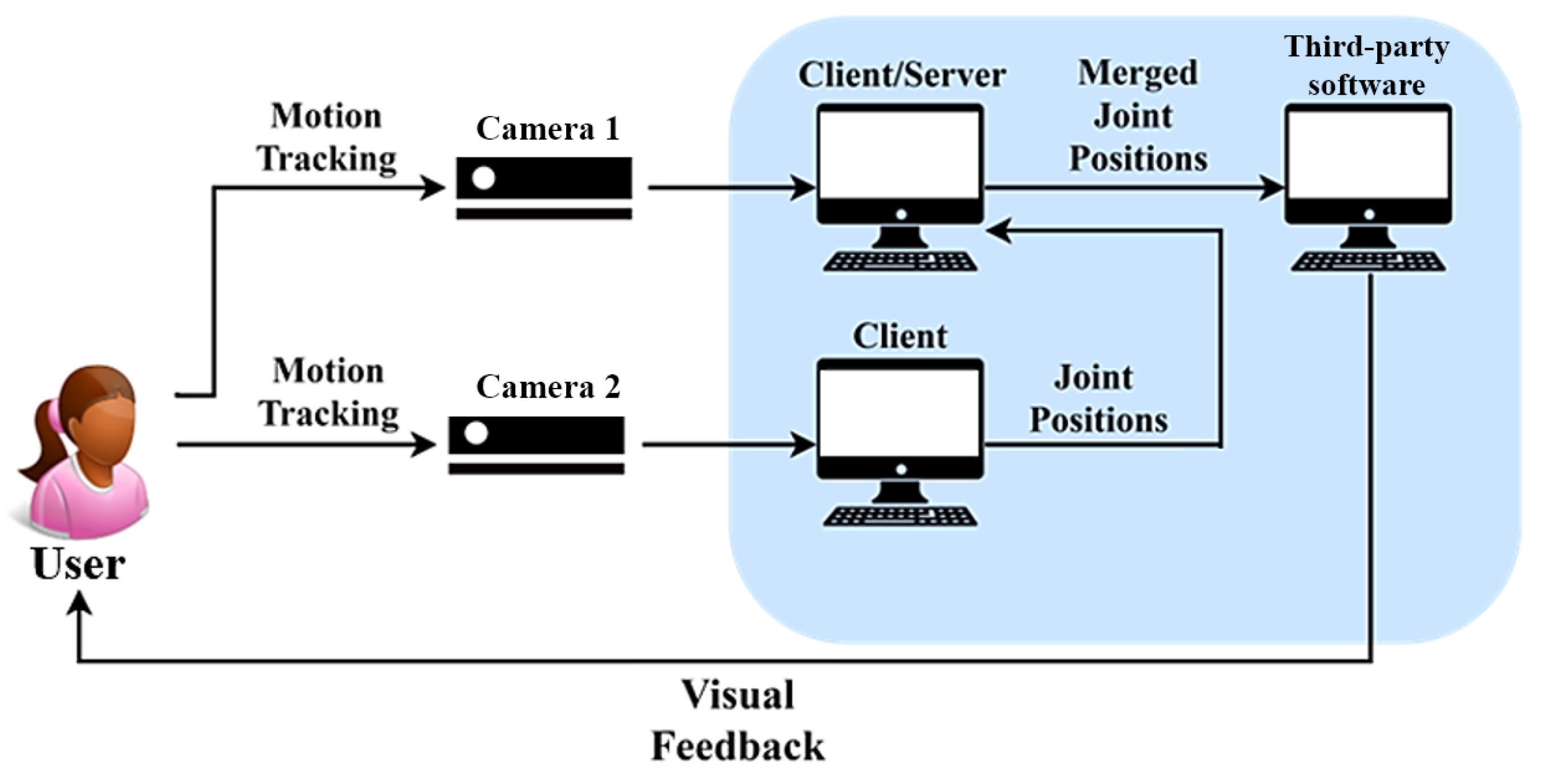
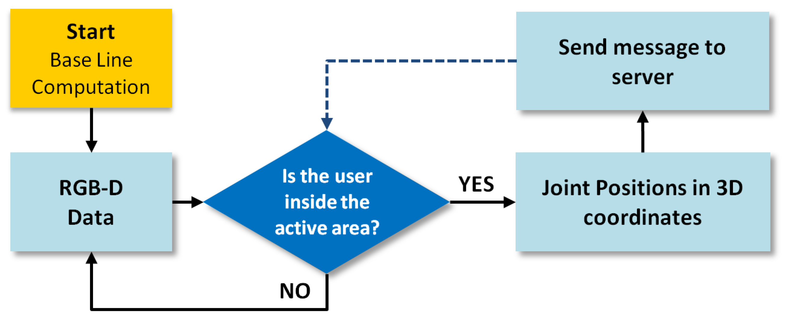
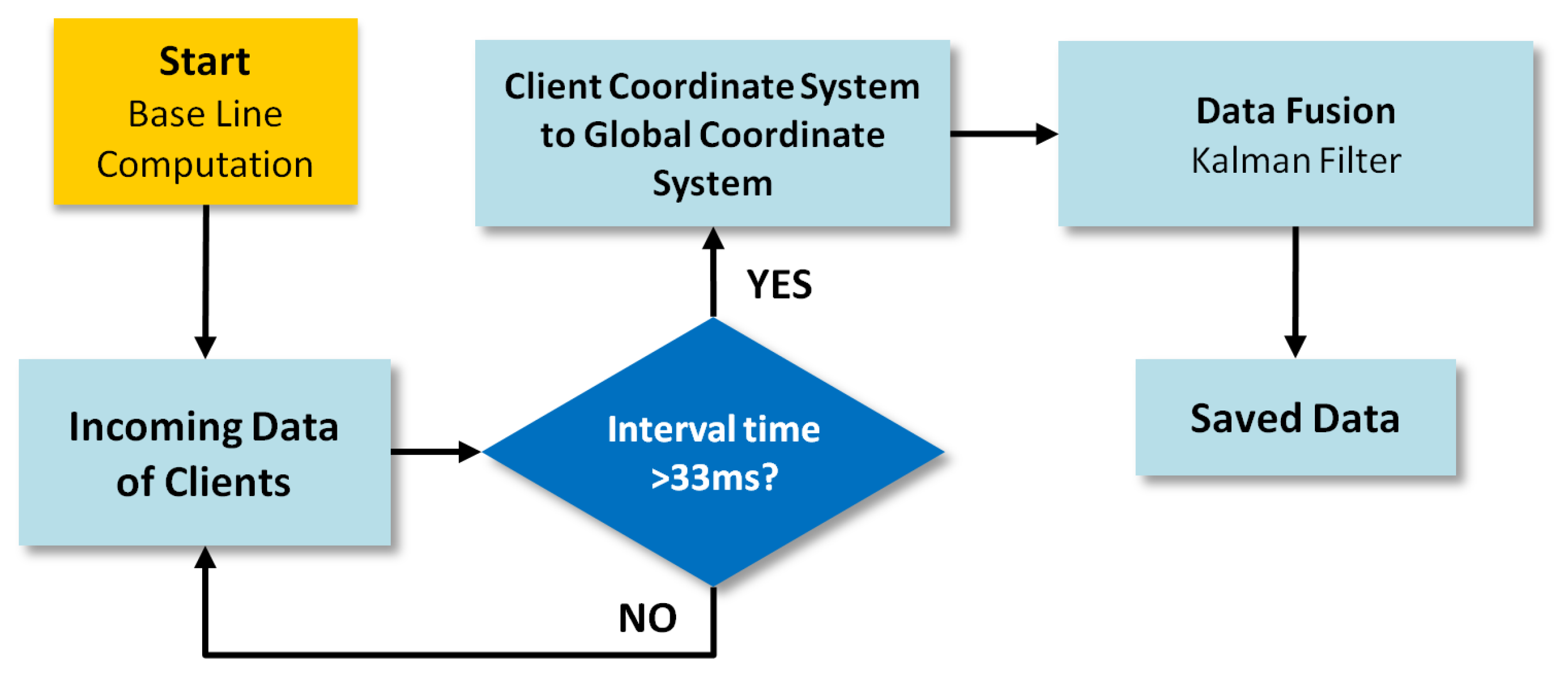
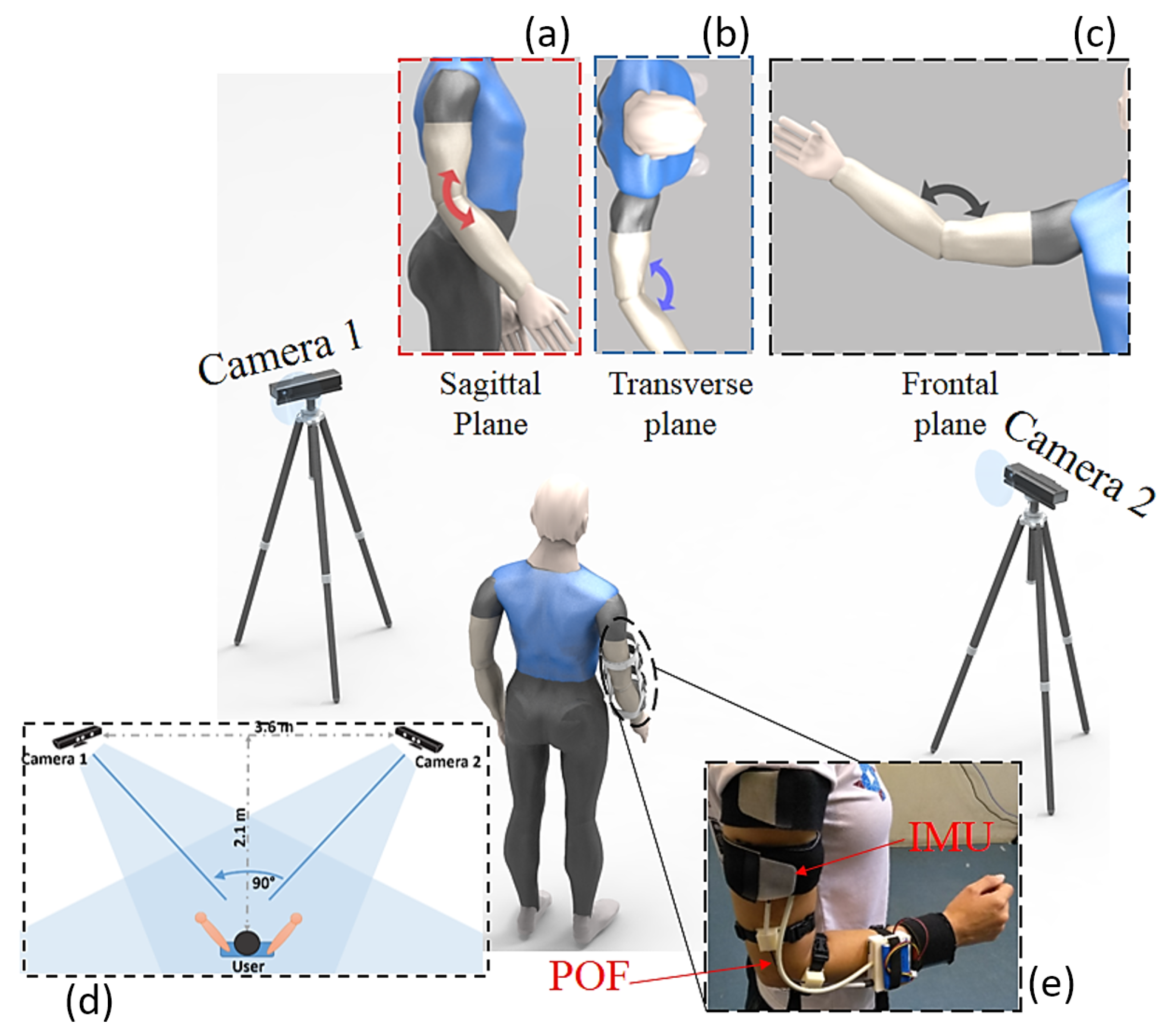
2.1. RGB-D Fusion System
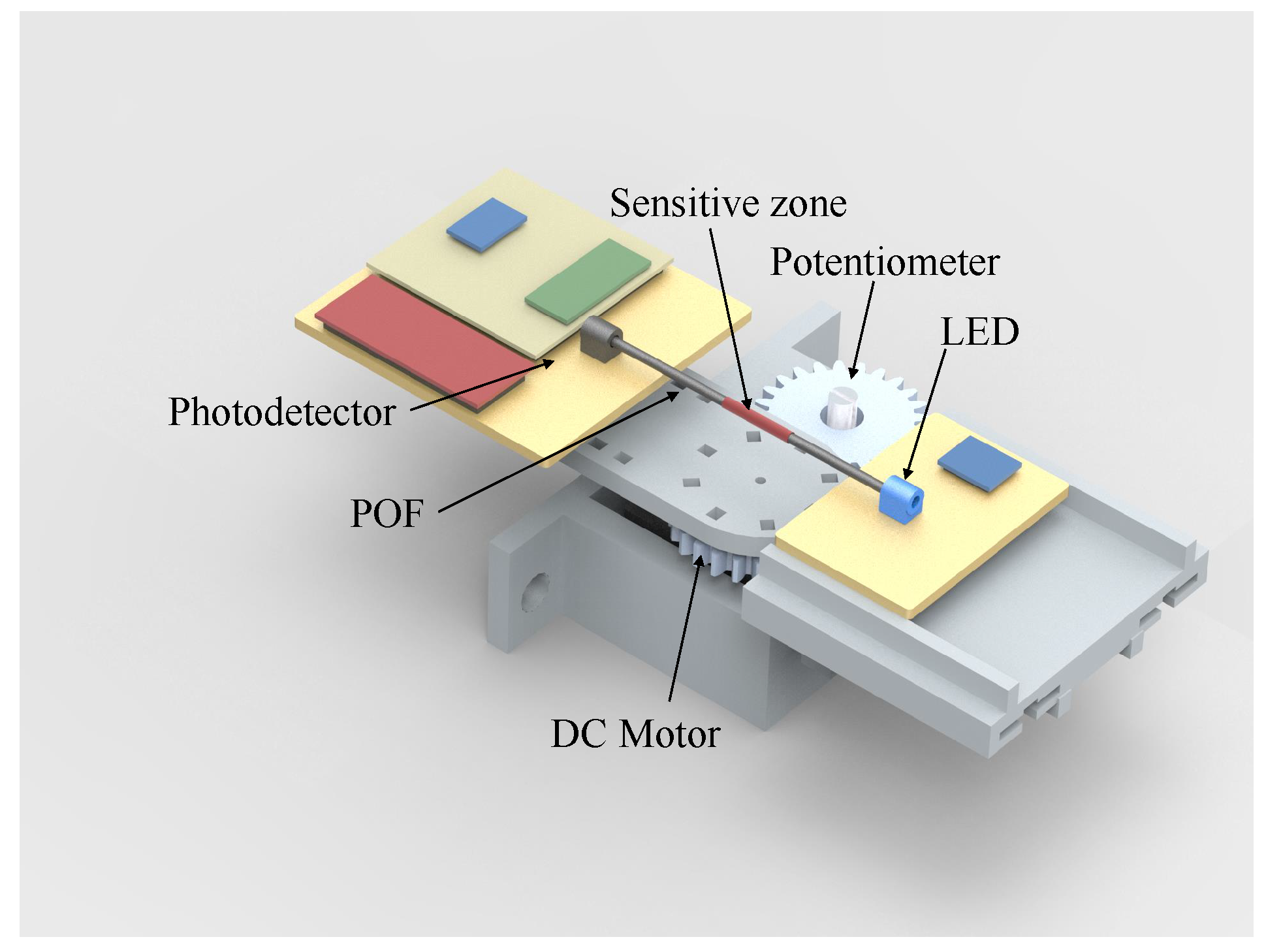
2.2. POF Sensor
2.3. IMU
- To calculate the rotation quaternion, , that aligns the x-axis of the coordinate system, , with the gravity vector is expressed in the global coordinate system () at the calibration moment, as proposed in [33].
- To define the technical-anatomical coordinate systems and , at the calibration moment, applying Equations (2) and (3).where ⊗ denotes the Hamilton product. Please note that due to the assumptions mentioned above, at the calibration moment, and are equals. Which means that the initial angle in a straight neutral posture is zero.
- To calculate sensor orientation () with respect to its associated body segment () using Equation (4). Please note that and are constant at all time instants.
2.4. Sensors Characterization
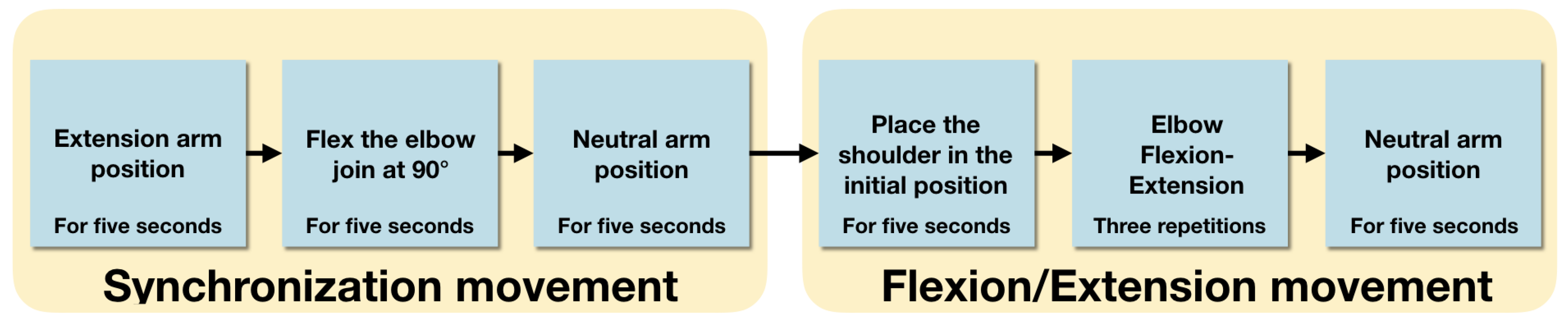
2.5. Experimental Protocol
3. Results and Discussion
3.1. Sensors Characterization
3.1.1. IMUs and RGB-D Cameras
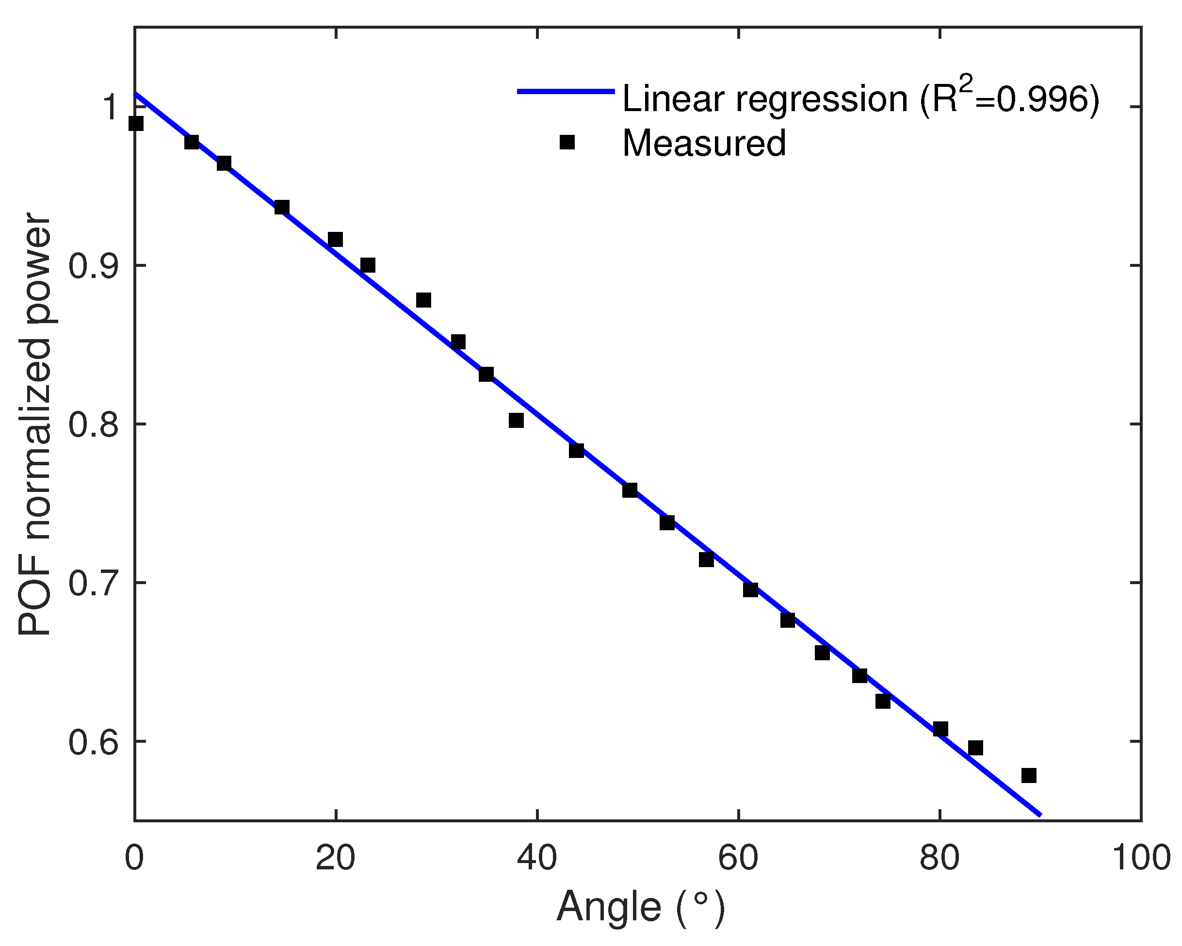
3.1.2. POF
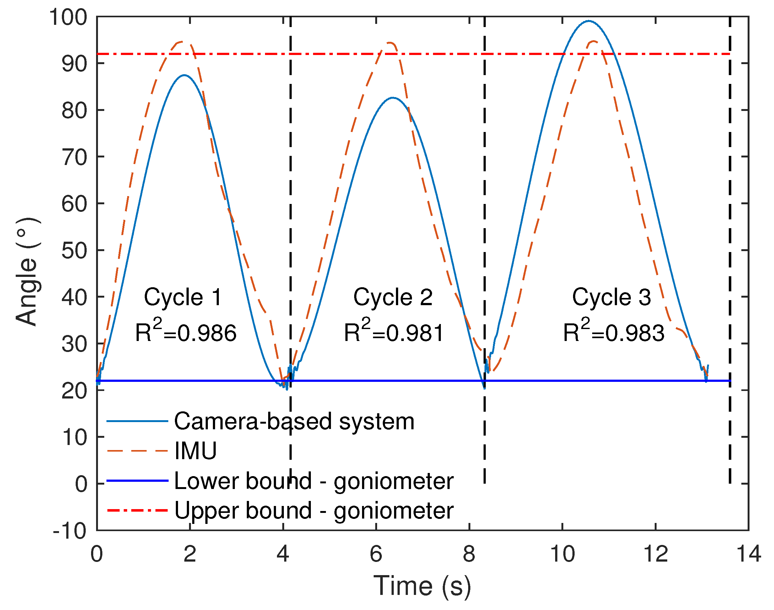
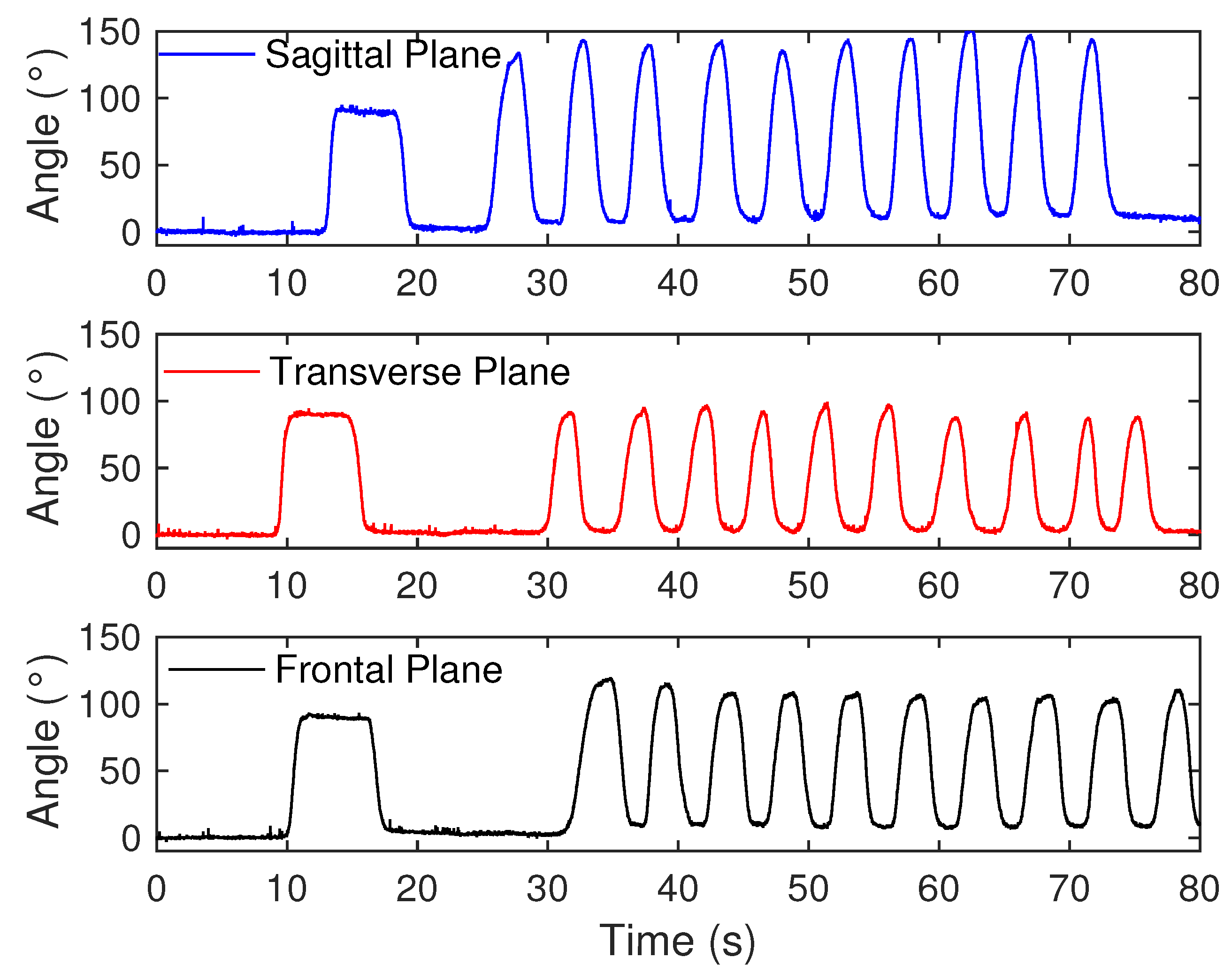
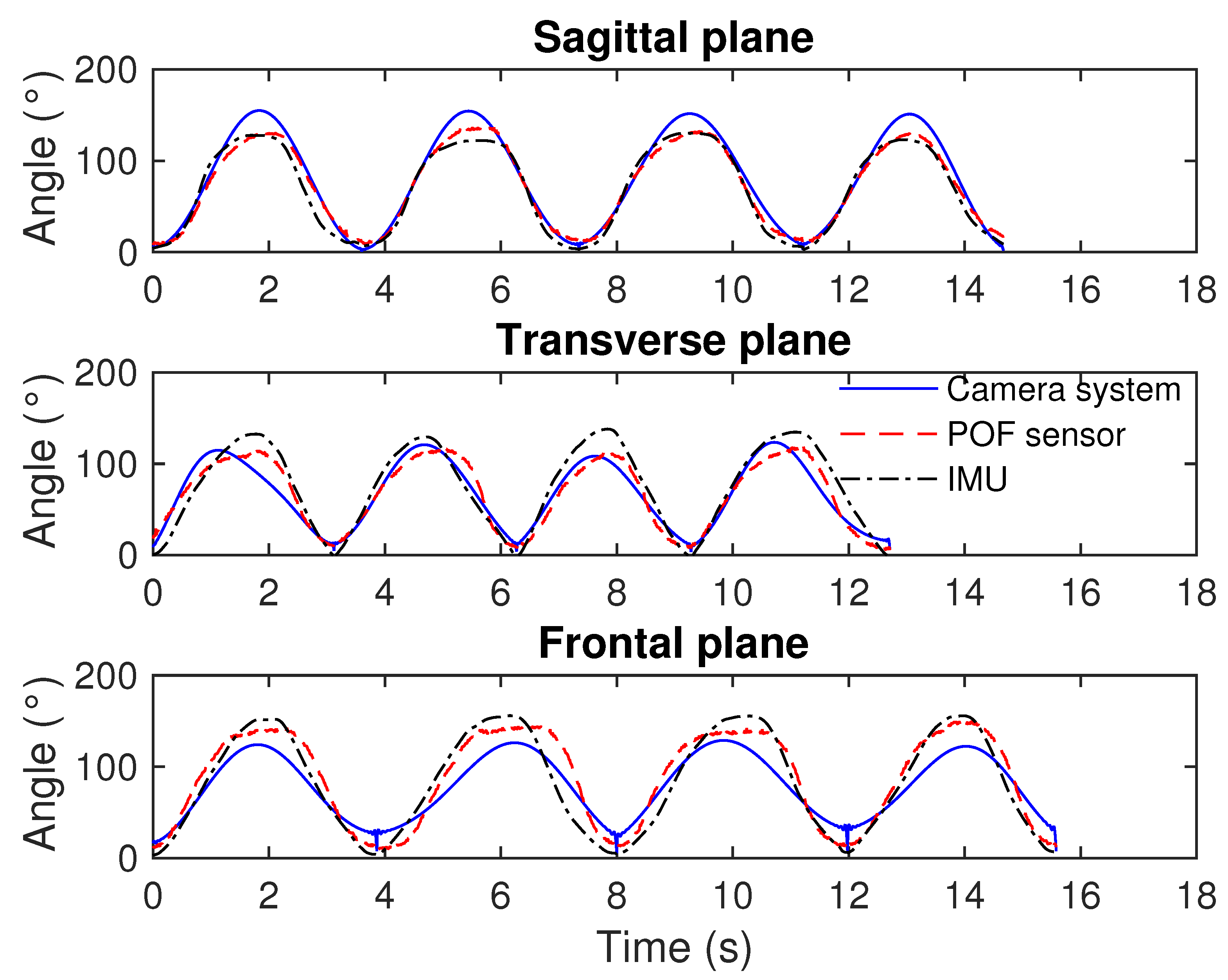
3.2. Comparison among the Sensors
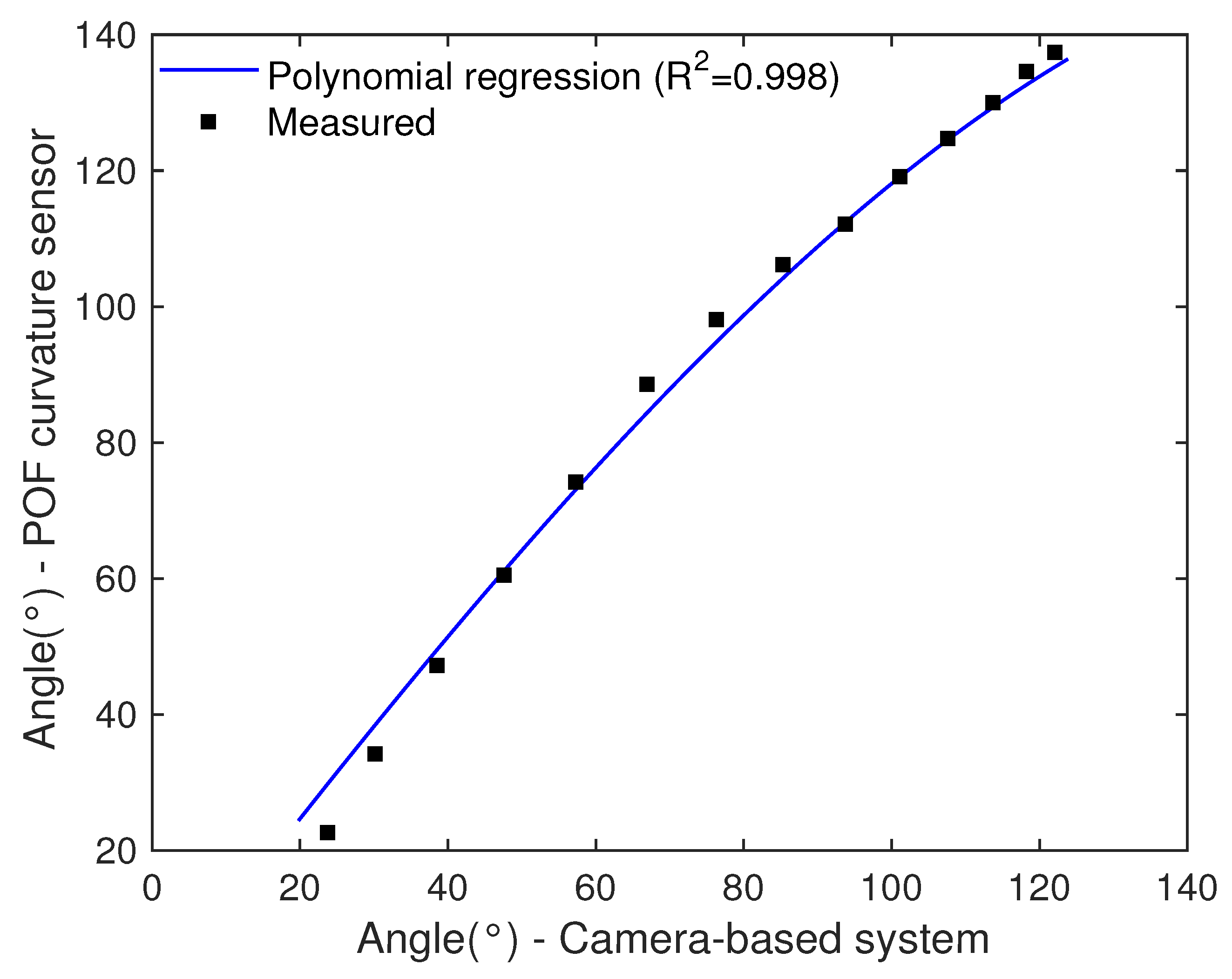
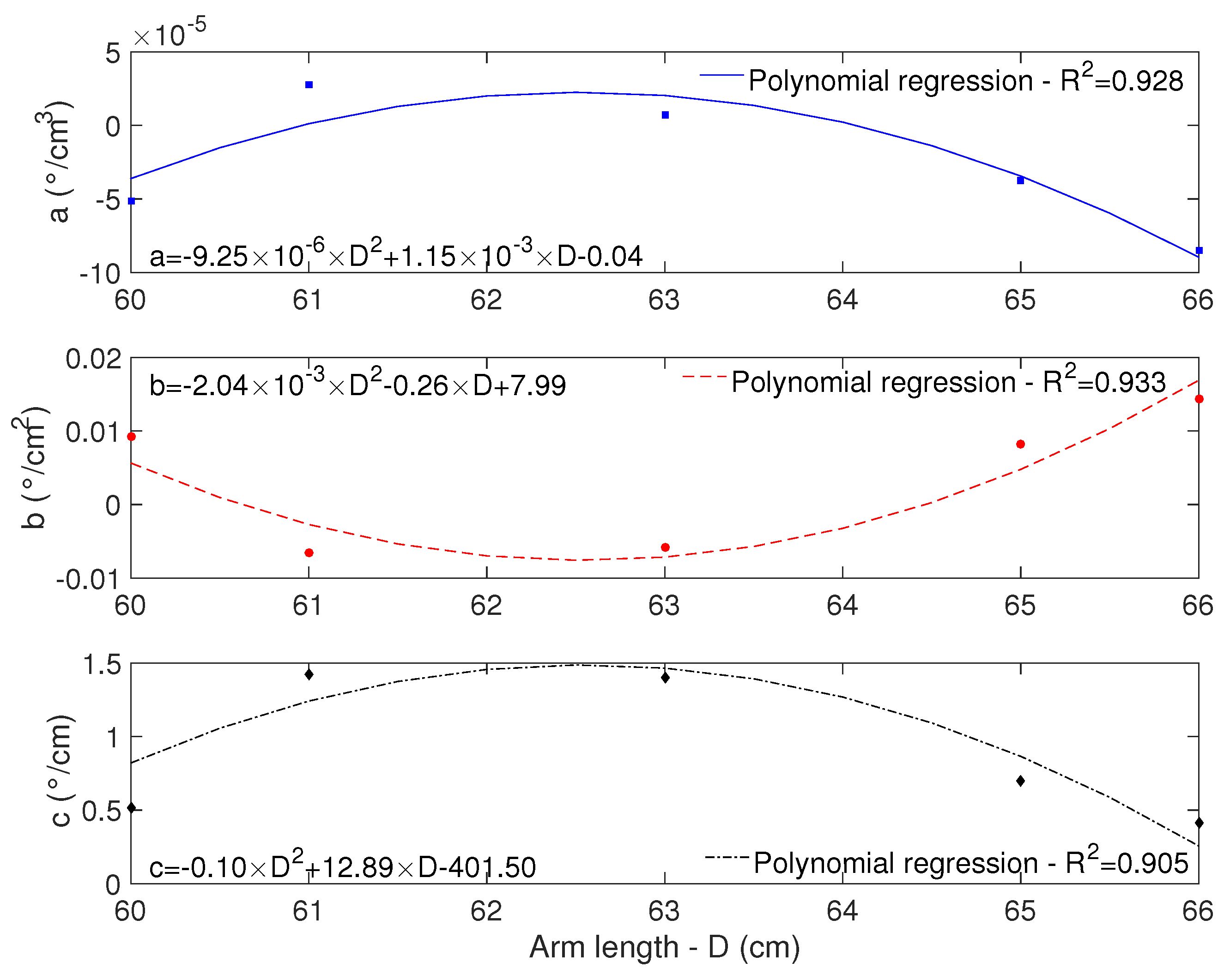
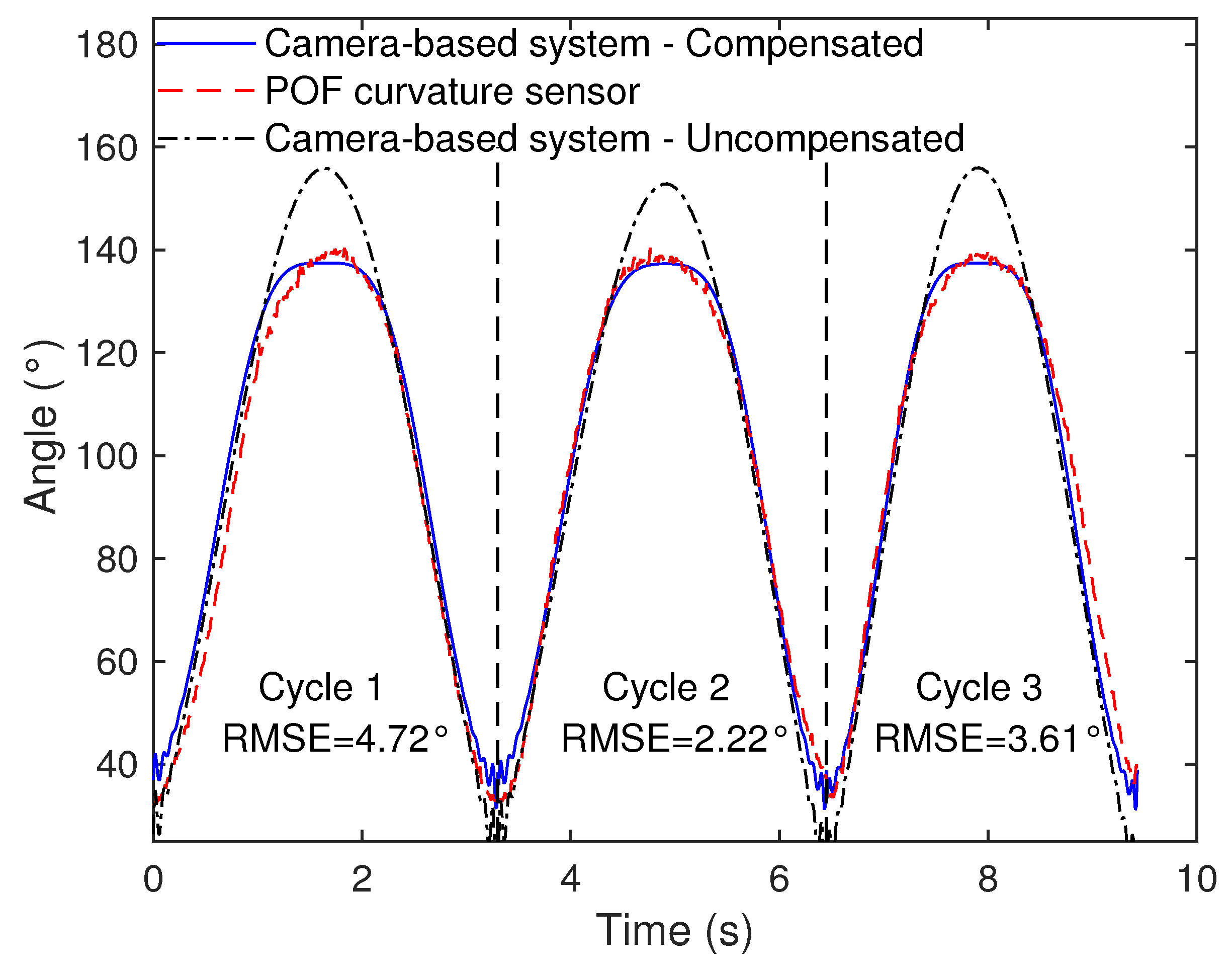
3.3. Technique for Angle Correction in Markerless Camera-Based Systems
4. Conclusions
Author Contributions
Funding
Conflicts of Interest
Abbreviations
| RGB-D | Red-Blue-Green-and-Depth information |
| IMU | Inertial Measurement Unit |
| POF | Polymer Optical Fiber |
| DOF | Degree of Freedom |
| MEM | Micro-Electro-Mechanical |
| ROS | Robot Operating System |
| XML | eXtensible Markup Language |
| RPC | Remote Procedure Call |
| NTP | Network Time Protocol |
References
- Hashimoto, K.; Higuchi, K.; Nakayama, Y.; Abo, M. Ability for basic movement as an early predictor of functioning related to activities of daily living in stroke patients. Neurorehabilit. Neural Repair 2007, 21, 353–357. [Google Scholar] [CrossRef] [PubMed]
- Casamassima, F.; Ferrari, A.; Milosevic, B.; Ginis, P.; Farella, E.; Rocchi, L. A wearable system for gait training in subjects with Parkinson’s disease. Sensors 2014, 14, 6229–6246. [Google Scholar] [CrossRef] [PubMed]
- Van Den Noort, J.C.; Ferrari, A.; Cutti, A.G.; Becher, J.G.; Harlaar, J. Gait analysis in children with cerebral palsy via inertial and magnetic sensors. Med. Biol. Eng. Comput. 2013, 51, 377–386. [Google Scholar] [CrossRef] [PubMed]
- Muro-de-la Herran, A.; García-Zapirain, B.; Méndez-Zorrilla, A. Gait analysis methods: An overview of wearable and non-wearable systems, highlighting clinical applications. Sensors 2014, 14, 3362–3394. [Google Scholar] [CrossRef] [PubMed]
- Shull, P.B.; Jirattigalachote, W.; Hunt, M.A.; Cutkosky, M.R.; Delp, S.L. Quantified self and human movement: A review on the clinical impact of wearable sensing and feedback for gait analysis and intervention. Gait Posture 2014, 40, 11–19. [Google Scholar] [CrossRef] [PubMed]
- Wong, C.; Zhang, Z.Q.; Lo, B.; Yang, G.Z. Wearable Sensing for Solid Biomechanics: A Review. IEEE Sens. J. 2015, 15, 2747–2760. [Google Scholar] [CrossRef]
- Hawkins, D. A new instrumentation system for training rowers. J. Biomech. 2000, 33, 241–245. [Google Scholar] [CrossRef]
- Wang, P.T.; King, C.E.; Do, A.H.; Nenadic, Z. A durable, low-cost electrogoniometer for dynamic measurement of joint trajectories. Med. Eng. Phys. 2011, 33, 546–552. [Google Scholar] [CrossRef]
- El-Gohary, M.; McNames, J. Shoulder and Elbow Joint Angle Tracking with Inertial Sensors. IEEE Trans. Biomed. Eng. 2012, 59, 2635–2641. [Google Scholar] [CrossRef]
- Peters, K. Polymer optical fiber sensors—A review. Smart Mater. Struct. 2011, 20, 013002. [Google Scholar] [CrossRef]
- Leal-Junior, A.G.; Frizera, A.; Vargas-Valencia, L.; Dos Santos, W.M.; Bo, A.P.; Siqueira, A.A.; Pontes, M.J. Polymer Optical Fiber Sensors in Wearable Devices: Toward Novel Instrumentation Approaches for Gait Assistance Devices. IEEE Sens. J. 2018, 18, 7085–7092. [Google Scholar] [CrossRef]
- Leal-Junior, A.; Theodosiou, A.; Díaz, C.; Marques, C.; Pontes, M.J.; Kalli, K.; Frizera-Neto, A. Polymer optical fiber Bragg Gratings in CYTOP Fibers for angle measurement with dynamic compensation. Polymers 2018, 10, 674. [Google Scholar] [CrossRef]
- Gong, Y.; Zhao, T.; Rao, Y.J.; Wu, Y. All-fiber curvature sensor based on multimode interference. IEEE Photonics Technol. Lett. 2011, 23, 679–681. [Google Scholar] [CrossRef]
- Bilro, L.; Alberto, N.; Pinto, J.L.; Nogueira, R. Optical sensors based on plastic fibers. Sensors 2012, 12, 12184–12207. [Google Scholar] [CrossRef] [PubMed]
- Leal-Junior, A.; Frizera, A.; Marques, C.; José Pontes, M. Polymer-optical-fiber-based sensor system for simultaneous measurement of angle and temperature. Appl. Opt. 2018, 57, 1717–1723. [Google Scholar] [CrossRef] [PubMed]
- Wu, G.; Van Der Helm, F.C.; Veeger, H.E.; Makhsous, M.; Van Roy, P.; Anglin, C.; Nagels, J.; Karduna, A.R.; McQuade, K.; Wang, X.; et al. ISB recommendation on definitions of joint coordinate systems of various joints for the reporting of human joint motion—Part II: Shoulder, elbow, wrist and hand. J. Biomech. 2005, 38, 981–992. [Google Scholar] [CrossRef]
- Menezes, R.C.; Batista, P.K.; Ramos, A.Q.; Medeiros, A.F. Development of a complete game based system for physical therapy with kinect. In Proceedings of the 2014 IEEE 3nd International Conference on Serious Games and Applications for Health (SeGAH), Rio de Janeiro, Brazil, 14–16 May 2014; pp. 1–6. [Google Scholar]
- Svendsen, J.; Albu, A.B.; Virji-Babul, N. Analysis of patterns of motor behavior in gamers with down syndrome. In Proceedings of the IEEE Computer Society Conference on Computer Vision and Pattern Recognition Workshops, Colorado Springs, CO, USA, 20–25 June 2011. [Google Scholar] [CrossRef]
- Cameirao, M.S.; Bermudez i Badia, S.; Duarte Oller, E.; Verschure, P.F. Neurorehabilitation using the virtual reality based Rehabilitation Gaming System: Methodology, design, psychometrics, usability and validation. J. Neuroeng. Rehabil. 2010, 7, 48. [Google Scholar] [CrossRef]
- Müller, B.; Ilg, W.; Giese, M.A.; Ludolph, N. Validation of enhanced Kinect sensor based motion capturing system for gait assessment. PLoS ONE 2017, 12, e0175813. [Google Scholar] [CrossRef]
- Konstantinidis, E.I.; Billis, A.S.; Paraskevopoulos, I.T.; Bamidis, P.D. The interplay between IoT and serious games towards personalised healthcare. In Proceedings of the 9th International Conference on Virtual Worlds and Games for Serious Applications (VS-Games), Athens, Greece, 6–8 September 2017; pp. 249–252. [Google Scholar] [CrossRef]
- Covaci, A.; Kramer, D.; Augusto, J.C.; Rus, S.; Braun, A. Assessing Real World Imagery in Virtual Environments for People with Cognitive Disabilities. In Proceedings of the 2015 International Conference on Intelligent Environments, Prague, Czech Republic, 15–17 July 2015; pp. 41–48. [Google Scholar]
- Abellard, A.; Abellard, P.; Applications, A.H. Serious Games Adapted to Children with Profound Intellectual and Multiple Disabilities. In Proceedings of the 9th International Conference on Virtual Worlds and Games for Serious Applications (VS-Games), Athens, Greece, 6–8 September 2017; pp. 183–184. [Google Scholar]
- Brandão, A.; Trevisan, D.G.; Brandão, L.; Moreira, B.; Nascimento, G.; Vasconcelos, C.N.; Clua, E.; Mourão, P.T. Semiotic inspection of a game for children with Down syndrome. In Proceedings of the 2010 Brazilian Symposium on Games and Digital Entertainment, Florianopolis, Brazil, 8–10 November 2010; pp. 199–210. [Google Scholar] [CrossRef]
- Chen, P.J.; Du, Y.C.; Shih, C.B.; Yang, L.C.; Lin, H.T.; Fan, S.C. Development of an upper limb rehabilitation system using inertial movement units and kinect device. In Proceedings of the 2016 International Conference on Advanced Materials for Science and Engineering (ICAMSE), Tainan, Taiwan, 12–13 November 2016; pp. 275–278. [Google Scholar]
- Lee, J.H.; Nguyen, V.V. Full-body imitation of human motions with kinect and heterogeneous kinematic structure of humanoid robot. In Proceedings of the 2012 IEEE/SICE International Symposium on System Integration (SII), Fukuoka, Japan, 16–18 December 2012; pp. 93–98. [Google Scholar]
- Qi, Y.; Soh, C.B.; Gunawan, E.; Low, K.S.; Maskooki, A. A novel approach to joint flexion/extension angles measurement based on wearable UWB radios. IEEE J. Biomed. Health Inform. 2014, 18, 300–308. [Google Scholar]
- Xu, Y.; Yang, C.; Zhong, J.; Wang, N.; Zhao, L. Robot teaching by teleoperation based on visual interaction and extreme learning machine. Neurocomputing 2018, 275, 2093–2103. [Google Scholar] [CrossRef]
- Leal Junior, A.G.; Frizera, A.; Pontes, M.J. Analytical model for a polymer optical fiber under dynamic bending. Opt. Laser Technol. 2017, 93, 92–98. [Google Scholar] [CrossRef]
- Zubia, J.; Arrue, J. Plastic optical fibers: An introduction to their technological processes and applications. Opt. Fiber Technol. 2001, 7, 101–140. [Google Scholar] [CrossRef]
- Leal-Junior, A.G.; Frizera, A.; José Pontes, M. Sensitive zone parameters and curvature radius evaluation for polymer optical fiber curvature sensors. Opt. Laser Technol. 2018, 100, 272–281. [Google Scholar] [CrossRef]
- Paulich, M.; Schepers, H.M.; Rudigkeit, N.; Bellusci, G. Xsens MTw Awinda: Miniature Wireless Inertial-Magnetic Motion Tracker for Highly Accurate 3D Kinematic Applications; Technical Report; XSens Technologies: Enschede, The Netherlands, 2018. [Google Scholar]
- Vargas-Valencia, L.S.; Elias, A.; Rocon, E.; Bastos-Filho, T.; Frizera, A. An IMU-to-Body Alignment Method Applied to Human Gait Analysis. Sensors 2016, 16, 2090. [Google Scholar] [CrossRef] [PubMed]
- Cutti, A.G.; Giovanardi, A.; Rocchi, L.; Davalli, A.; Sacchetti, R. Ambulatory measurement of shoulder and elbow kinematics through inertial and magnetic sensors. Med. Biol. Eng. Comput. 2008, 46, 169–178. [Google Scholar] [CrossRef] [PubMed]
- Palermo, E.; Rossi, S.; Marini, F.; Patanè, F.; Cappa, P. Experimental evaluation of accuracy and repeatability of a novel body-to-sensor calibration procedure for inertial sensor-based gait analysis. Measurement 2014, 52, 145–155. [Google Scholar] [CrossRef]
- Laidig, D.; Müller, P.; Seel, T. Automatic anatomical calibration for IMU-based elbow angle measurement in disturbed magnetic fields. Curr. Dir. Biomed. Eng. 2017, 3, 167–170. [Google Scholar] [CrossRef]
- Seel, T.; Raisch, J.; Schauer, T. IMU-Based Joint Angle Measurement for Gait Analysis. Sensors 2014, 14, 6891–6909. [Google Scholar] [CrossRef]
- Tannous, H.; Istrate, D.; Benlarbi-Delai, A.; Sarrazin, J.; Gamet, D.; Ho Ba Tho, M.C.; Dao, T.T. A new multi-sensor fusion scheme to improve the accuracy of knee flexion kinematics for functional rehabilitation movements. Sensors 2016, 11, 1914. [Google Scholar] [CrossRef]
- Kirtly, C. Clinical Gait Analysis: Theory and Practice; Churchill Livingstone: London, UK, 2006; Volume 3, p. 2007. [Google Scholar]
- Schmitz, A.; Ye, M.; Shapiro, R.; Yang, R.; Noehren, B. Accuracy and repeatability of joint angles measured using a single camera markerless motion capture system. J. Biomech. 2014, 47, 587–591. [Google Scholar] [CrossRef]
- Gordon, C. Anthropometric Detailed Data Tables. 2006. Available online: https://multisite.eos.ncsu.edu/www-ergocenter-ncsu-edu/wp-content/uploads/sites/18/2016/06/Anthropometric-Detailed-Data-Tables.pdf (accessed on 26 November 2018).
- Piriyaprasarth, P.; Morris, M.E. Psychometric properties of measurement tools for quantifying knee joint position and movement: A systematic review. Knee 2007, 14, 2–8. [Google Scholar] [CrossRef] [PubMed]


| Subject | Age (Years) | Height (cm) | Weight (Kg) |
|---|---|---|---|
| M1 | 30 | 163 | 67 |
| M2 | 22 | 176 | 66 |
| M3 | 30 | 173 | 73 |
| M4 | 27 | 183 | 75 |
| M5 | 28 | 170 | 70 |
| F1 | 30 | 156 | 57 |
| F2 | 32 | 158 | 46 |
| F3 | 22 | 160 | 48 |
| F4 | 23 | 163 | 53 |
| F5 | 24 | 158 | 48 |
| F6 | 33 | 176 | 89 |
| Cycle 1 | Cycle 2 | Cycle 3 | ||||
|---|---|---|---|---|---|---|
| Max [°] | Min [°] | Max [°] | Min [°] | Max [°] | Min [°] | |
| Camera | 87.4 | 21.0 | 82.6 | 12.8 | 99.0 | 22.2 |
| IMU | 94.6 | 22.9 | 94.4 | 22.7 | 94.7 | 23.0 |
| Goniometer | 90.0 | 20.0 | 90.0 | 20.0 | 90.0 | 20.0 |
| Sagittal | Frontal | Transverse | ||||
|---|---|---|---|---|---|---|
| R2 | RMSE | R2 | RMSE | R2 | RMSE | |
| M1 | 0.994 ± 0.0041 | 13.53 ± 2.87 | 0.955 ± 0.0164 | 14.31 ± 6.37 | 0.988 ± 0.0043 | 18.62 ± 1.32 |
| M2 | 0.994 ± 0.0023 | 10.21 ± 1.86 | 0.983 ± 0.0213 | 11.96 ± 4.67 | 0.991 ± 0.0052 | 14.48 ± 4.53 |
| M3 | 0.986 ± 0.0052 | 7.42 ± 2.51 | 0.993 ± 0.0063 | 15.03 ± 1.55 | 0.984 ± 0.0060 | 18.84 ± 7.23 |
| M4 | 0.984 ± 0.0058 | 13.02 ± 3.12 | 0.982 ± 0.0026 | 9.99 ± 3.94 | 0.992 ± 0.0031 | 15.89 ± 6.59 |
| M5 | 0.991 ± 0.0025 | 9.60 ± 3.08 | 0.989 ± 0.0095 | 14.34 ± 3.85 | 0.978 ± 0.0230 | 11.21 ± 2.90 |
| F1 | 0.993 ± 0.0011 | 11.83 ± 2.93 | 0.976 ± 0.0098 | 16.42 ± 2.41 | 0.991 ± 0.0077 | 17.61 ± 3.67 |
| F2 | 0.990 ± 0.0043 | 11.26 ± 2.89 | 0.986 ± 0.0045 | 8.49 ± 5.61 | 0.921 ± 0.0833 | 15.28 ± 4.31 |
| F3 | 0.974 ± 0.0136 | 12.04 ± 5.39 | 0.990 ± 0.0046 | 14.89 ± 1.90 | 0.956 ± 0.0543 | 16.73 ± 2.89 |
| F4 | 0.996 ± 0.0019 | 11.90 ± 3.53 | 0.989 ± 0.0057 | 15.98 ± 6.78 | 0.990 ± 0.0052 | 16.29 ± 5.98 |
| F5 | 0.993 ± 0.0079 | 9.89 ± 0.77 | 0.994 ± 0.0020 | 12.56 ± 3.74 | 0.987 ± 0.0037 | 19.42 ± 5.03 |
| F6 | 0.995 ± 0.0042 | 11.81 ± 0.52 | 0.989 ± 0.0034 | 17.31 ± 4.04 | 0.992 ± 0.0006 | 19.98 ± 6.52 |
| Sagittal | Frontal | Transverse | ||||
|---|---|---|---|---|---|---|
| R2 | RMSE | R2 | RMSE | R2 | RMSE | |
| M1 | 0.988 ± 0.0066 | 10.01 ± 2.12 | 0.972 ± 0.0175 | 15.32 ± 6.92 | 0.994 ± 0.0033 | 19.32 ± 3.30 |
| M2 | 0.977 ± 0.0055 | 10.90 ± 1.67 | 0.985 ± 0.0065 | 11.28 ± 0.97 | 0.985 ± 0.0080 | 14.98 ± 4.83 |
| M3 | 0.978 ± 0.0110 | 6.90 ± 2.25 | 0.967 ± 0.0025 | 16.14 ± 2.74 | 0.981 ± 0.0123 | 19.83 ± 3.80 |
| M4 | 0.955 ± 0.0208 | 12.00 ± 2.83 | 0.916 ± 0.0106 | 13.35 ± 4.23 | 0.965 ± 0.0165 | 13.53 ± 5.28 |
| M5 | 0.994 ± 0.0017 | 10.87 ± 0.15 | 0.973 ± 0.0069 | 13.26 ± 3.39 | 0.954 ± 0.0289 | 11.60 ± 1.17 |
| F1 | 0.975 ± 0.0178 | 11.52 ± 3.24 | 0.978 ± 0.0196 | 14.84 ± 1.09 | 0.970 ± 0.0205 | 17.84 ± 3.44 |
| F2 | 0.983 ± 0.0120 | 10.35 ± 0.60 | 0.987 ± 0.0051 | 9.42 ± 4.27 | 0.945 ± 0.0375 | 17.44 ± 4.77 |
| F3 | 0.982 ± 0.0085 | 7.72 ± 1.59 | 0.978 ± 0.0070 | 17.17 ± 1.80 | 0.982 ± 0.0083 | 17.86 ± 5.20 |
| F4 | 0.978 ± 0.0098 | 12.76 ± 1.63 | 0.975 ± 0.0076 | 16.95 ± 4.46 | 0.987 ± 0.0001 | 17.71 ± 6.52 |
| F5 | 0.989 ± 0.0097 | 8.11 ± 0.81 | 0.977 ± 0.0070 | 13.56 ± 4.30 | 0.979 ± 0.0131 | 19.28 ± 5.49 |
| F6 | 0.964 ± 0.0076 | 13.52 ± 0.95 | 0.892 ± 0.0165 | 19.13 ± 4.53 | 0.979 ± 0.0047 | 18.92 ± 5.36 |
| Subject | RMSE-Compensated | RMSE-Uncompensated |
|---|---|---|
| M1 | 3.52 ± 0.84 | 10.01 ± 2.12 |
| M2 | 3.99 ± 1.15 | 10.90 ± 1.67 |
| M3 | 4.79 ± 0.74 | 6.90 ± 2.25 |
| M4 | 6.24 ± 1.66 | 12.00 ± 2.83 |
| M5 | 4.64 ± 1.23 | 10.87 ± 0.15 |
| F1 | 3.52 ± 1.25 | 11.52 ± 3.24 |
| F2 | 4.22 ± 2.25 | 10.35 ± 0.60 |
| F3 | 4.11 ± 1.31 | 7.72 ± 1.59 |
| F4 | 5.36 ± 2.05 | 12.76 ± 1.63 |
| F5 | 5.74 ± 0.77 | 8.11 ± 0.81 |
| F6 | 4.79 ± 1.06 | 13.52 ± 0.95 |
© 2019 by the authors. Licensee MDPI, Basel, Switzerland. This article is an open access article distributed under the terms and conditions of the Creative Commons Attribution (CC BY) license (http://creativecommons.org/licenses/by/4.0/).
Share and Cite
Valencia-Jimenez, N.; Leal-Junior, A.; Avellar, L.; Vargas-Valencia, L.; Caicedo-Rodríguez, P.; Ramírez-Duque, A.A.; Lyra, M.; Marques, C.; Bastos, T.; Frizera, A. A Comparative Study of Markerless Systems Based on Color-Depth Cameras, Polymer Optical Fiber Curvature Sensors, and Inertial Measurement Units: Towards Increasing the Accuracy in Joint Angle Estimation. Electronics 2019, 8, 173. https://doi.org/10.3390/electronics8020173
Valencia-Jimenez N, Leal-Junior A, Avellar L, Vargas-Valencia L, Caicedo-Rodríguez P, Ramírez-Duque AA, Lyra M, Marques C, Bastos T, Frizera A. A Comparative Study of Markerless Systems Based on Color-Depth Cameras, Polymer Optical Fiber Curvature Sensors, and Inertial Measurement Units: Towards Increasing the Accuracy in Joint Angle Estimation. Electronics. 2019; 8(2):173. https://doi.org/10.3390/electronics8020173
Chicago/Turabian StyleValencia-Jimenez, Nicolas, Arnaldo Leal-Junior, Leticia Avellar, Laura Vargas-Valencia, Pablo Caicedo-Rodríguez, Andrés A. Ramírez-Duque, Mariana Lyra, Carlos Marques, Teodiano Bastos, and Anselmo Frizera. 2019. "A Comparative Study of Markerless Systems Based on Color-Depth Cameras, Polymer Optical Fiber Curvature Sensors, and Inertial Measurement Units: Towards Increasing the Accuracy in Joint Angle Estimation" Electronics 8, no. 2: 173. https://doi.org/10.3390/electronics8020173
APA StyleValencia-Jimenez, N., Leal-Junior, A., Avellar, L., Vargas-Valencia, L., Caicedo-Rodríguez, P., Ramírez-Duque, A. A., Lyra, M., Marques, C., Bastos, T., & Frizera, A. (2019). A Comparative Study of Markerless Systems Based on Color-Depth Cameras, Polymer Optical Fiber Curvature Sensors, and Inertial Measurement Units: Towards Increasing the Accuracy in Joint Angle Estimation. Electronics, 8(2), 173. https://doi.org/10.3390/electronics8020173