Low Profile Sinuous Slot Antenna for UWB Sensor Networks


 ,
,  , ,
, , 
 and
and
Abstract
:
1. Introduction
2. Design of the Antenna Geometry
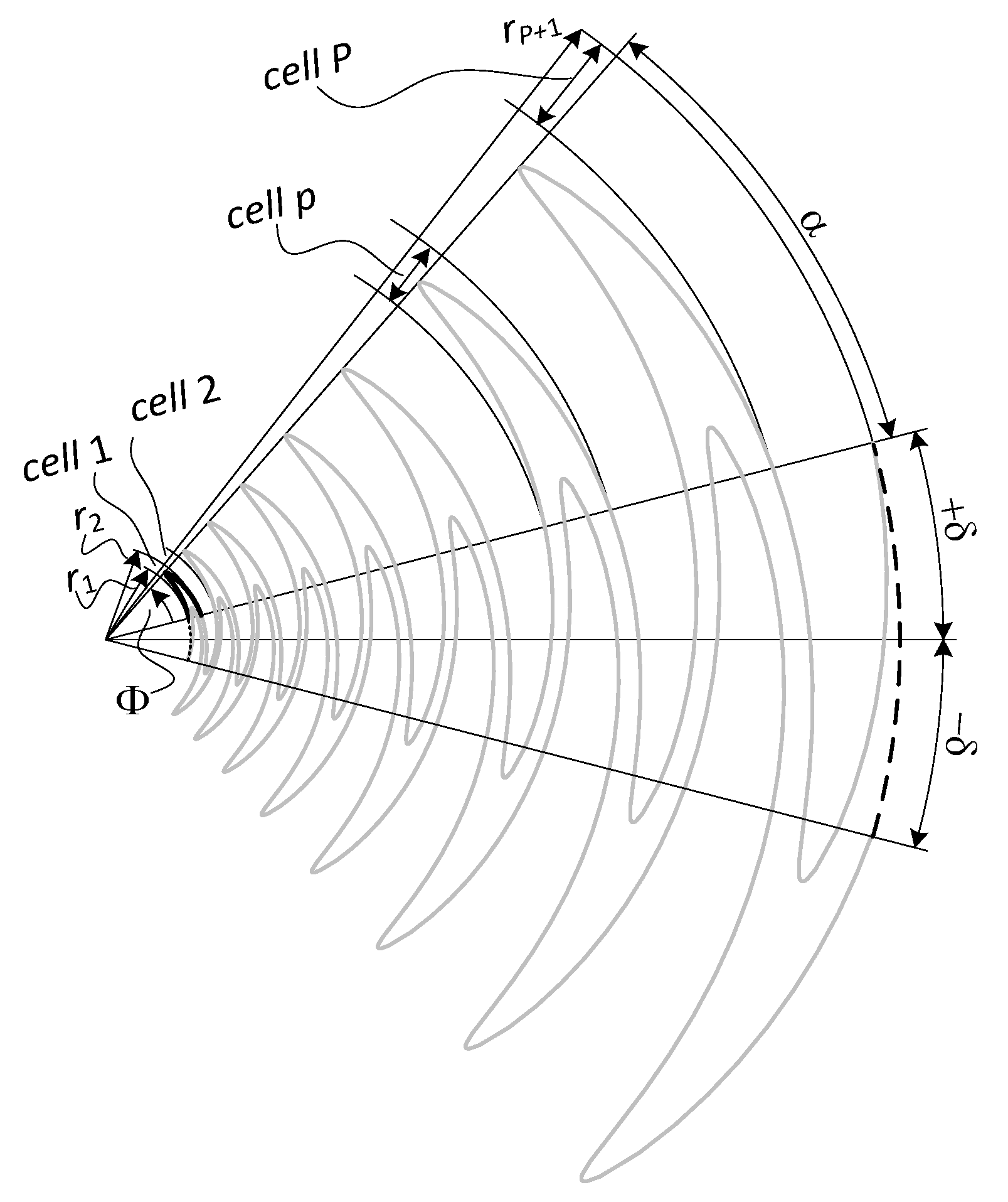
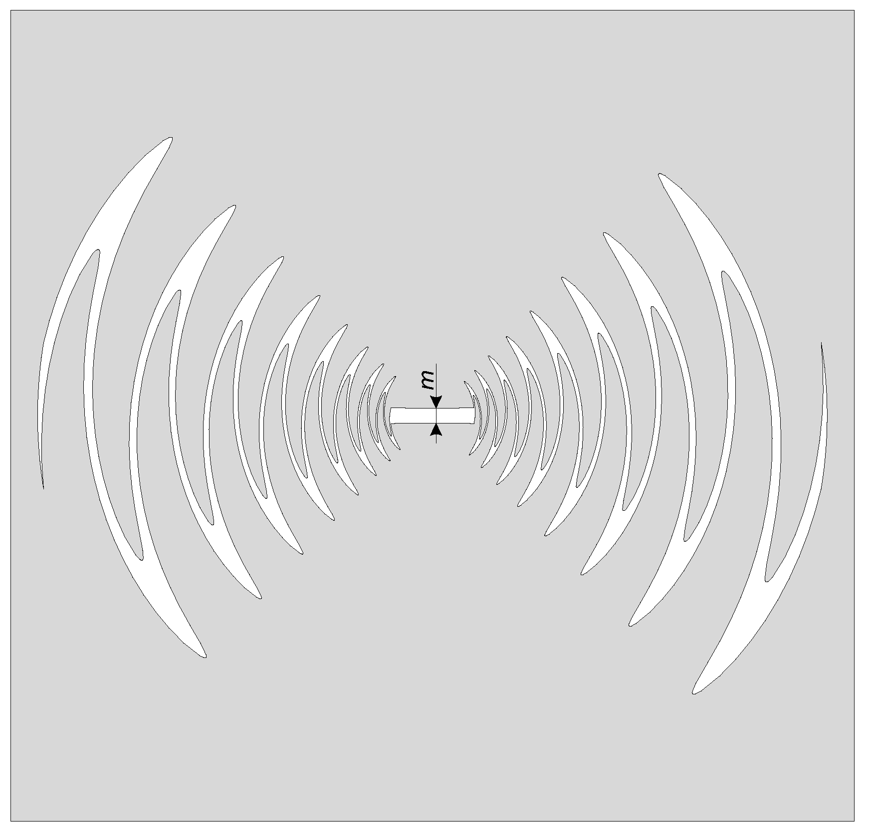
2.1. Basic Shape
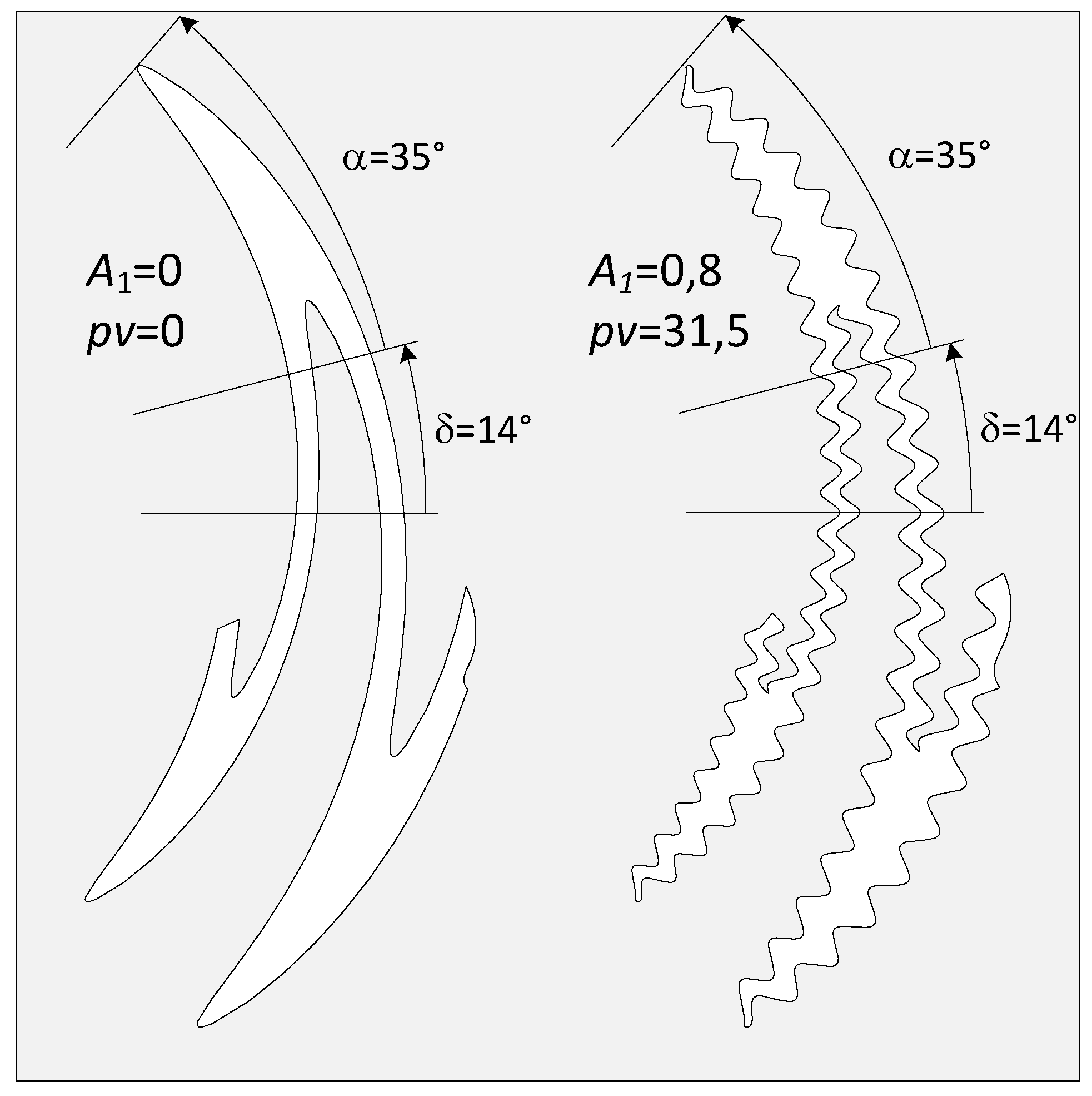
2.2. Antenna Ripple
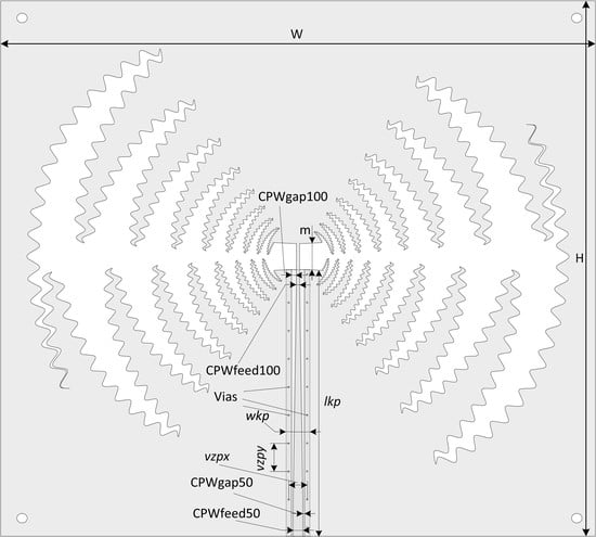
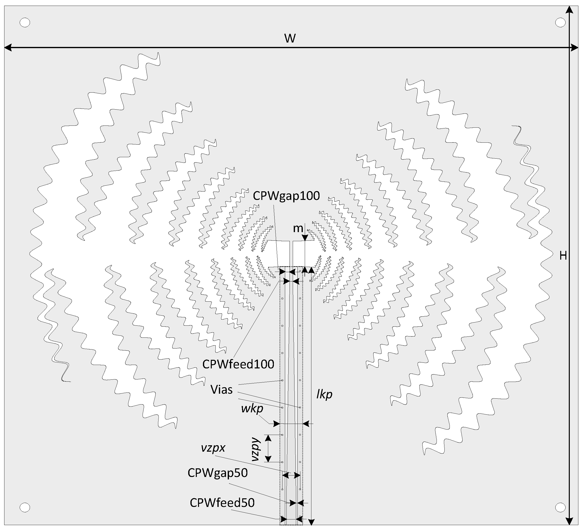
2.3. Antenna Feeding
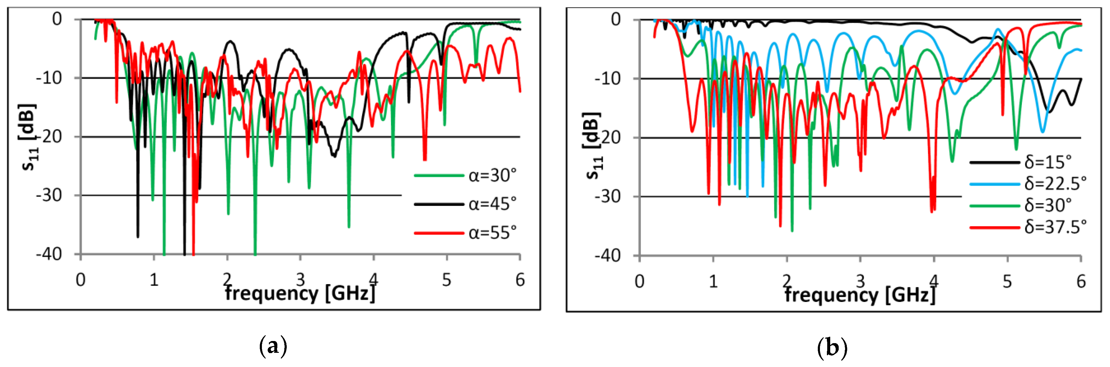
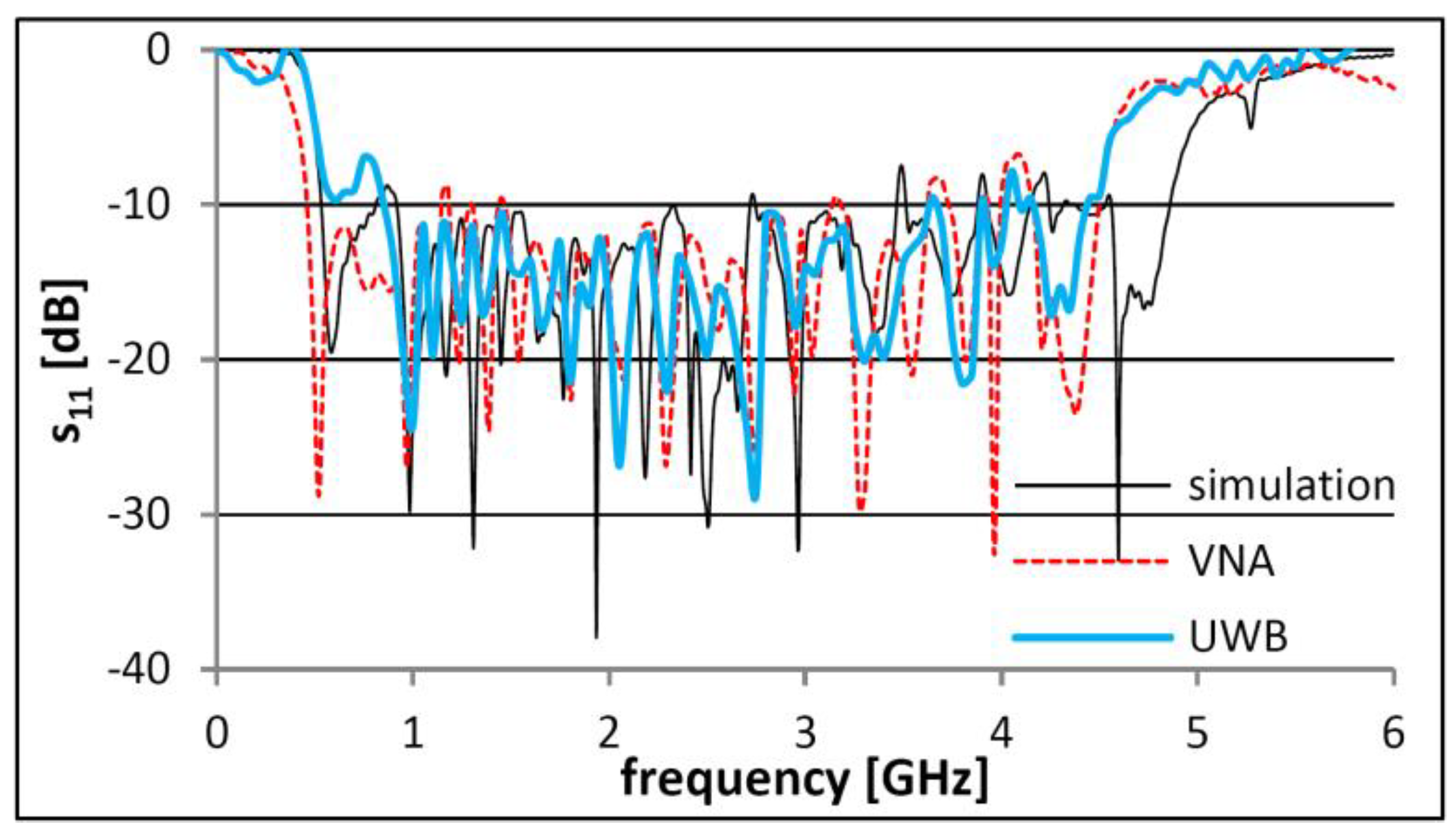
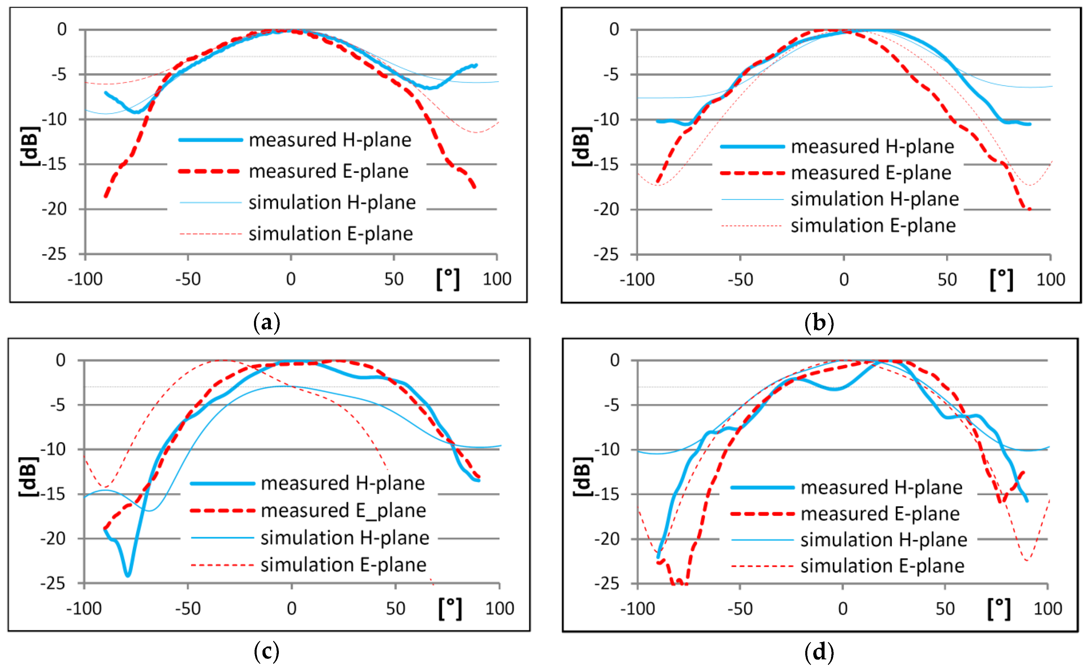
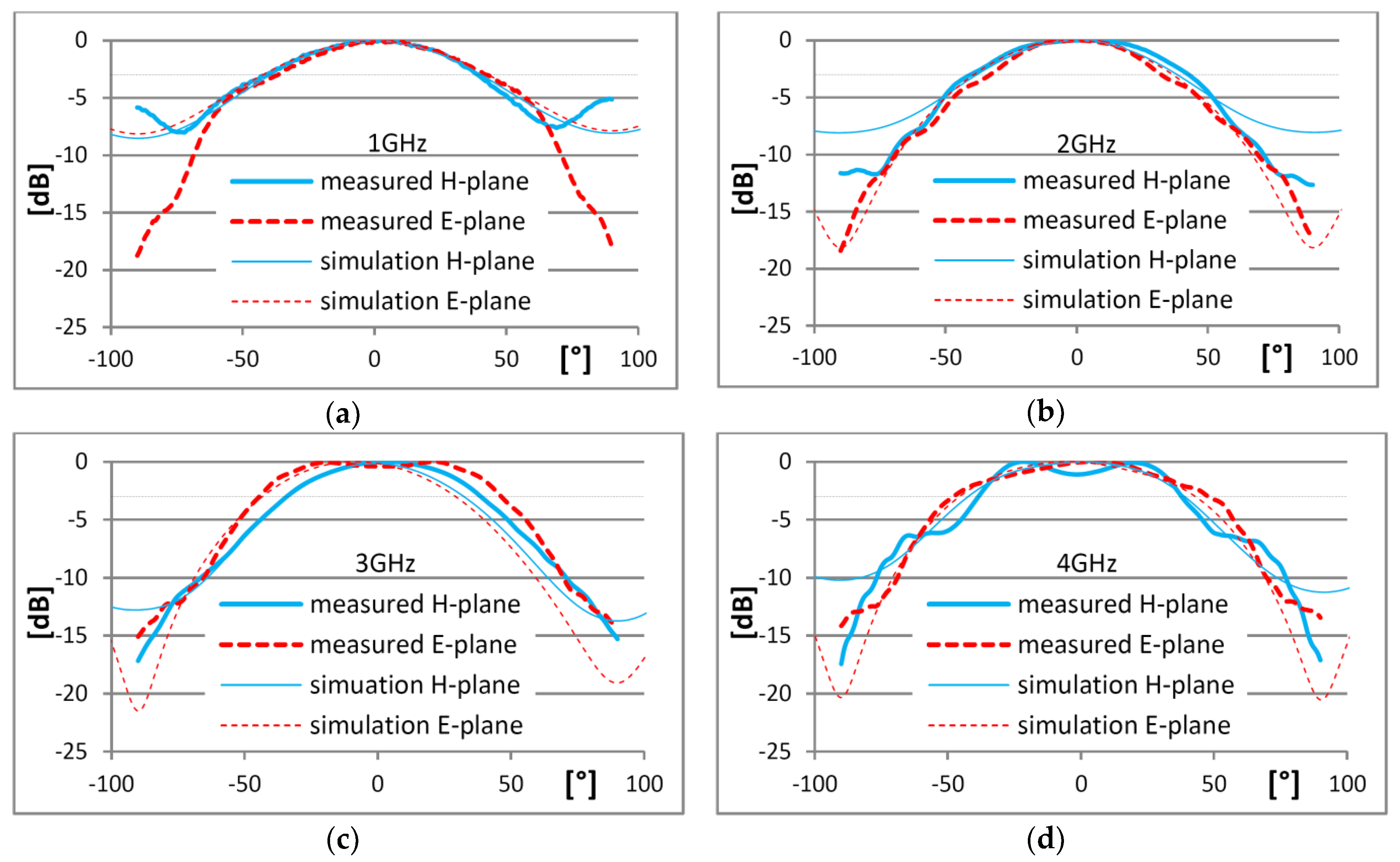
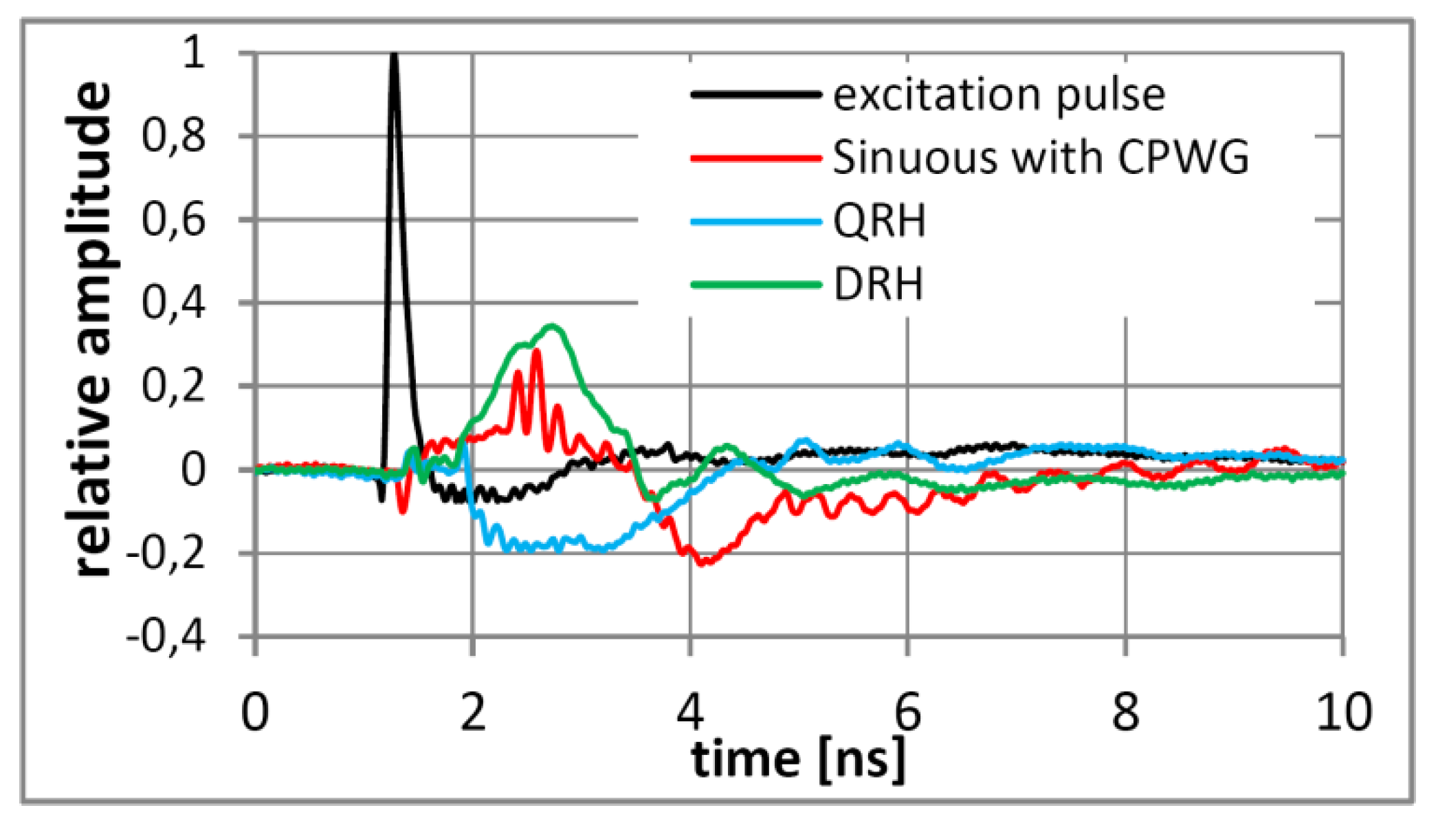
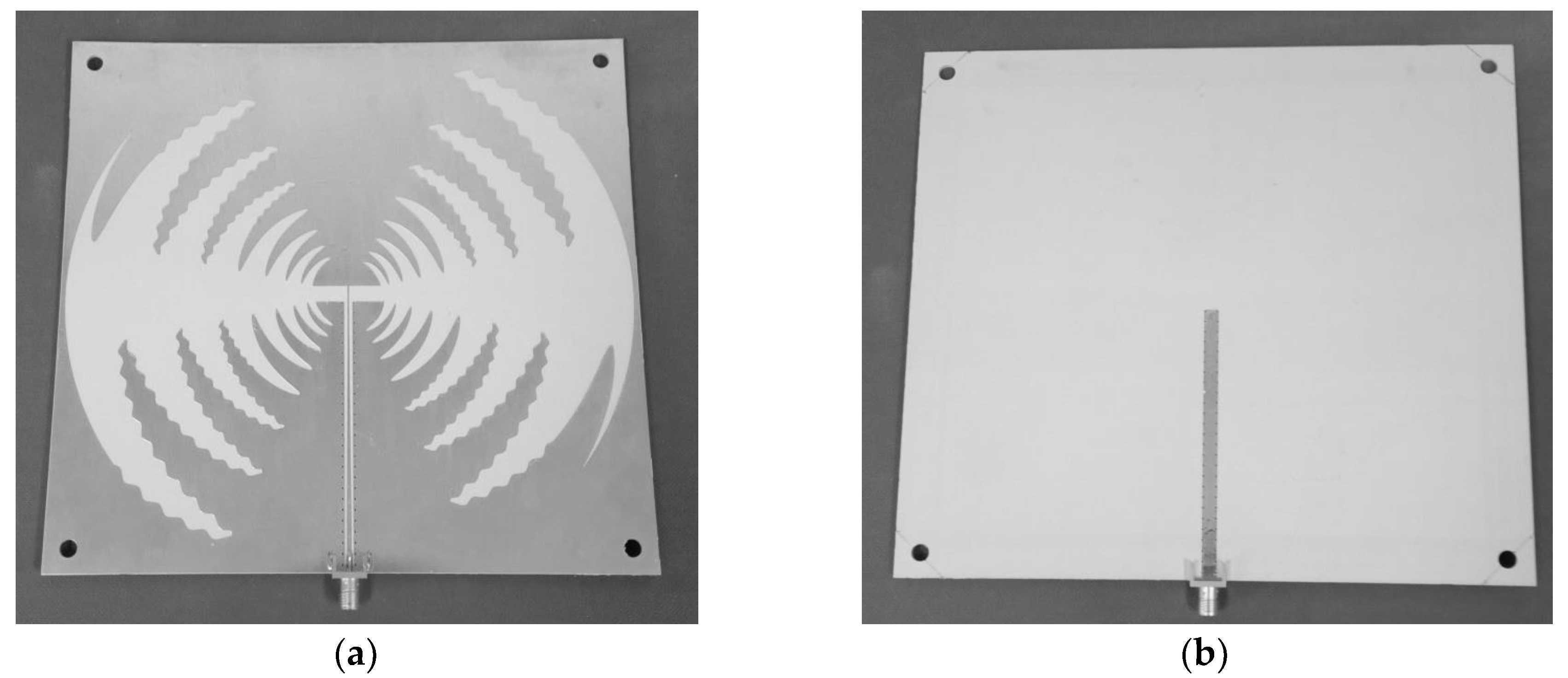
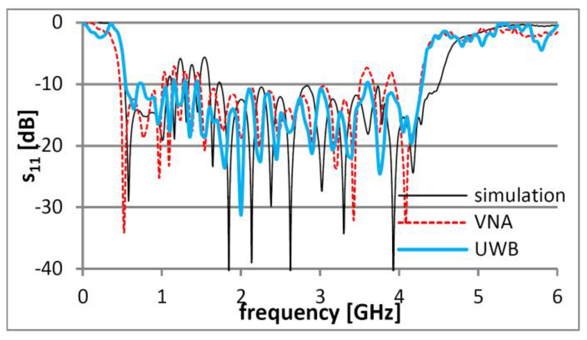
3. Results
4. Discussion and Conclusions
Author Contributions
Funding
Acknowledgments
Conflicts of Interest
References
- Fujimoto, K.; Morishita, H. Modern Small Antennas; Cambridge University Press: New York, NY, USA, 2014; p. 482. ISBN 978-0-521-87786-2. [Google Scholar]
- Schantz, H.G. The Art and Science of Ultrawideband Antennas, 2nd ed.; Artech House: Boston, MA, USA, 2015; p. 563. ISBN 978-1-60807-955-1. [Google Scholar]
- Staderini, E.M. UWB radars in medicine. IEEE Aerosp. Electron. Syst. Mag. 2002, 17, 13–18. [Google Scholar] [CrossRef]
- Žiga, M.; Galajda, P.; Slovák, S.; Kmec, M. Determination of the quality of frying oil based on UWB impedance spectrometer. In Proceedings of the 16th International Radar Symposium (IRS 2015), Dresden, Germany, 24–26 June 2015; pp. 955–960. [Google Scholar]
- Marpaung, D.H.N.; Yilong, L. A comparative study of migration algorithms for UWB GPR images in SISO-SAR and MIMO array configuration. In Proceedings of the 15th International Radar Symposium (IRS 2014), Gdansk, Poland, 16–18 June 2014; pp. 1–4. [Google Scholar]
- Novák, D.; Zetik, R.; Kocur, D. Defective localization of target in UWB radar applications. In Proceedings of the 24th International Conference Radioelektronika 2014, Bratislava, Slovakia, 15–16 April 2014; pp. 1–4. [Google Scholar]
- Yukhanov, Y.V.; Privalova, T.Y.; Kriuk, E.V. Characteristics of Vivaldi antennas in the radiation and scattering mode. In Proceedings of the International Conference on Electromagnetics in Advanced Applications (ICEAA 2018), Cartagena de Indias, Colombia, 10–14 September 2018; pp. 236–239. [Google Scholar]
- Schneider, J.; Gamec, J. Overview of UWB Low-profile planar antennas. Acta Electrotech. Inform. 2014, 14, 55–59. [Google Scholar] [CrossRef]
- Gupta, N.P.; Maheshwari, R.; Kumar, M. Advancement in ultra wideband antennas for wearable applications. Int. J. Sci. Eng. Res. 2013, 4, 341–248. [Google Scholar]
- Elsheakh, D.M. Planar antenna for RF energy harvesting applications. In Proceedings of the 2017 IEEE International Symposium on Antennas and Propagation & USNC/URSI National Radio Science Meeting, San Diego, CA, USA, 9–14 July 2017; pp. 1171–1172. [Google Scholar]
- Schneider, J.; Mrnka, M.; Gamec, J.; Gamcova, M.; Raida, Z. Vivaldi antenna for RF energy harvesting. Radioengineering 2016, 25, 666–671. [Google Scholar] [CrossRef]
- Kocur, D.; Kažimír, P.; Fortes, J.; Novák, D.; Drutarovský, M.; Galajda, P.; Zetik, R. Short-range UWB radar: Surveillance robot equipment of the future. In Proceedings of the 2014 IEEE International Conference on Systems, Man, and Cybernetics (SMC 2014), San Diego, CA, USA, 5–8 October 2014; pp. 3767–3772. [Google Scholar]
- DuHamel, R.H. Dual Polarized Sinuous Antennas. U.S. Patent 4 658 262, 14 April 1987. [Google Scholar]
- Rahman, M.; NaghshvarianJahromi, M.; Mirjavadi, S.S.; Hamouda, A.M. Resonator based switching technique between ultra wide band (UWB) and single/dual continuously tunable-notch behaviors in UWB radar for wireless vital signs monitoring. Sensors 2018, 18, 3330. [Google Scholar] [CrossRef] [PubMed]
- Rahman, M.; NaghshvarianJahromi, M.; Mirjavadi, S.S.; Hamouda, A.M. Bandwidth enhancement and frequency scanning array antenna using novel UWB filter integration technique for OFDM UWB radar applications in wireless vital signs monitoring. Sensors 2018, 18, 3155. [Google Scholar] [CrossRef] [PubMed]
- NejatiJahromi, M.; NaghshvarianJahromi, M.; Rahman, M.A. New compact planar antenna for switching between UWB, narrow band and UWB with tunable-notch behaviors for UWB and WLAN applications. Appl. Comput. Electrom. 2018, 33, 400–406. [Google Scholar]
- Rahman, M.; Ko, D.-S.; Park, J.-D. A Compact multiple notched ultra-wide band antenna with an analysis of the CSRR-TO-CSRR coupling for portable UWB applications. Sensors 2017, 17, 2174. [Google Scholar] [CrossRef] [PubMed]
- NaghshvarianJahromi, M. Compact UWB bandnotch antenna with transmission-line-FED. Prog. Electromagn. Res. B 2008, 3, 283–293. [Google Scholar] [CrossRef]
- Saini, K.S.; Bradley, R.F. The sinuous antenna—A dual polarized element for wideband phased array feed application. In Electronics Division Internal Report No. 301; National Radio Astronomy Observatory: Green Bank, WV, USA, 1996; p. 20. [Google Scholar]
- Alotaibi, I.M.; Hong, J.; Almorqi, S.K. Cavity-backed dual linear polarization sinuous antenna with integrated microstrip balun feed. In Proceedings of the 15th Mediterranean Microwave Symposium (MMS 2015), Lecce, Italy, 30 November–2 December 2015; pp. 1–4. [Google Scholar]
- Chen, X.; Fang, L.; Wu, X.; He, C. Design of ultra-wideband sinuous antenna applied for respiratory monitor. In Proceedings of the 2016 Asia-Pacific International Symposium on Electromagnetic Compatibility (APEMC 2016), Shenzhen, China, 17–21 May 2016; pp. 256–258. [Google Scholar]
- Novák, D.; Schneider, J.; Kocur, D. Static person detection and localization based on their respiratory motion using various antenna types. Acta Electrotech. Inf. 2016, 16, 54–59. [Google Scholar] [CrossRef]
- Manna, A.; Baldonero, P.; Trotta, F. Novel UWB low-profile sinuous slot antenna. In Proceedings of the 5th European Conference on Antennas and Propagation (EUCAP 2011), Rome, Italy, 11–15 April 2011; pp. 783–786. [Google Scholar]
- Stutzman, W.L.; Thiele, G.A. Antenna Theory and Design, 3rd ed.; John Wiley & Sons, Inc.: Hoboken, NJ, USA, 2013; pp. 1–822. ISBN 978-0-470-57664-9. [Google Scholar]
- Balanis, C.A. Antenna Theory Analysis and Design, 3rd ed.; John Wiley & Sons, Inc.: Hoboken, NJ, USA, 2005; pp. 1–1073. ISBN 0-471-66782-X. [Google Scholar]
- Kramer, B.A.; Chen, C.-C.; Volakis, J.L. Size reduction of a UWB low-profile spiral antenna using inductive and dielectric loading. IEEE Antenn. Wirel. Pr. 2008, 7, 22–25. [Google Scholar] [CrossRef]
- Schneider, J.; Gamec, J.; Gamcová, M.; Repko, M. Alternative antenna measuring methods with use of impulse UWB radar. In Proceedings of the 26th International Conference Radioelektronika 2016, Kosice, Slovakia, 19–20 April 2016; pp. 296–299. [Google Scholar]


| Parameter | Value | Parameter | Value | Parameter | Value |
|---|---|---|---|---|---|
| W | 170 mm | H | 160 mm | CPWfeed50 | 2 mm |
| α | 26.4˚ | δ | 38.3˚ | CPWgap50 | 0.4 mm |
| τ | 1.151 | r1 | 10 mm | CPWfeed100 | 0.6 mm |
| m | 4.8 mm | pv | 22.1 | CPWgap100 | 1.1 mm |
| A1 | 1.2 |
| Parameter | Value | Parameter | Value | Parameter | Value |
|---|---|---|---|---|---|
| W | 170 mm | H | 160 mm | wkp | 4 mm |
| α | 26.5˚ | δ | 38.3˚ | lkp | 77.65 mm |
| τ | 1.152 | r1 | 10 mm | vzpx | 3.5 mm |
| m | 4.7 mm | pv | 20 | vzpy | 3 mm |
| A1 | 1.2 | CPWfeed50 | 1.3 mm | CPWfeed100 | 0.4 mm |
| rv | 0.2 mm | CPWgap50 | 0.55 mm | CPWgap100 | 1.0 mm |
© 2019 by the authors. Licensee MDPI, Basel, Switzerland. This article is an open access article distributed under the terms and conditions of the Creative Commons Attribution (CC BY) license (http://creativecommons.org/licenses/by/4.0/).
Share and Cite
Gamec, J.; Repko, M.; Gamcová, M.; Gladišová, I.; Kurdel, P.; Nekrasov, A.; Fidge, C. Low Profile Sinuous Slot Antenna for UWB Sensor Networks. Electronics 2019, 8, 127. https://doi.org/10.3390/electronics8020127
Gamec J, Repko M, Gamcová M, Gladišová I, Kurdel P, Nekrasov A, Fidge C. Low Profile Sinuous Slot Antenna for UWB Sensor Networks. Electronics. 2019; 8(2):127. https://doi.org/10.3390/electronics8020127
Chicago/Turabian StyleGamec, Ján, Miroslav Repko, Mária Gamcová, Iveta Gladišová, Pavol Kurdel, Alexey Nekrasov, and Colin Fidge. 2019. "Low Profile Sinuous Slot Antenna for UWB Sensor Networks" Electronics 8, no. 2: 127. https://doi.org/10.3390/electronics8020127
APA StyleGamec, J., Repko, M., Gamcová, M., Gladišová, I., Kurdel, P., Nekrasov, A., & Fidge, C. (2019). Low Profile Sinuous Slot Antenna for UWB Sensor Networks. Electronics, 8(2), 127. https://doi.org/10.3390/electronics8020127