A Miniaturized Wideband Bandpass Filter Using Quarter-Wavelength Stepped-Impedance Resonators


Abstract
1. Introduction
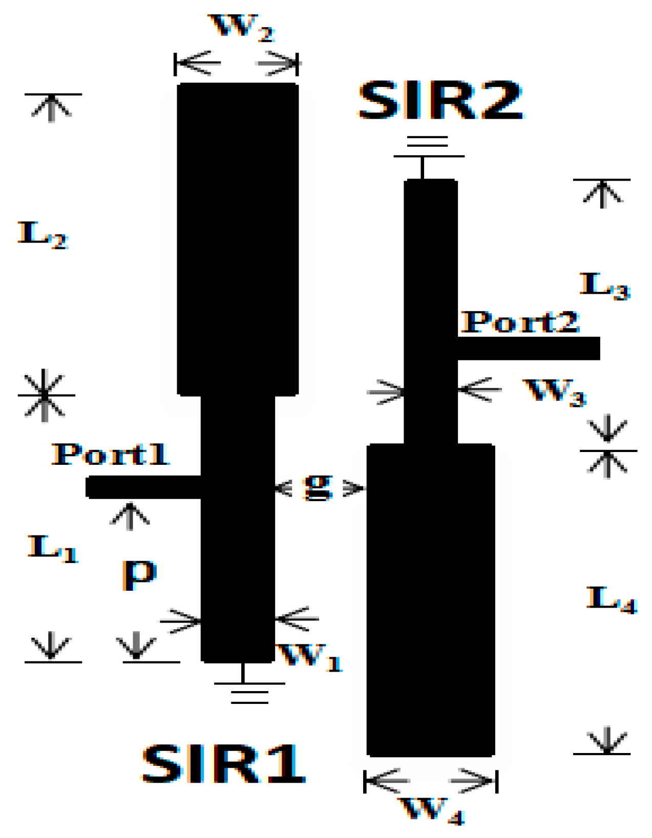
2. Design Procedure
Analysis of Quarter-Wavelength Stepped-Impedance Resonator
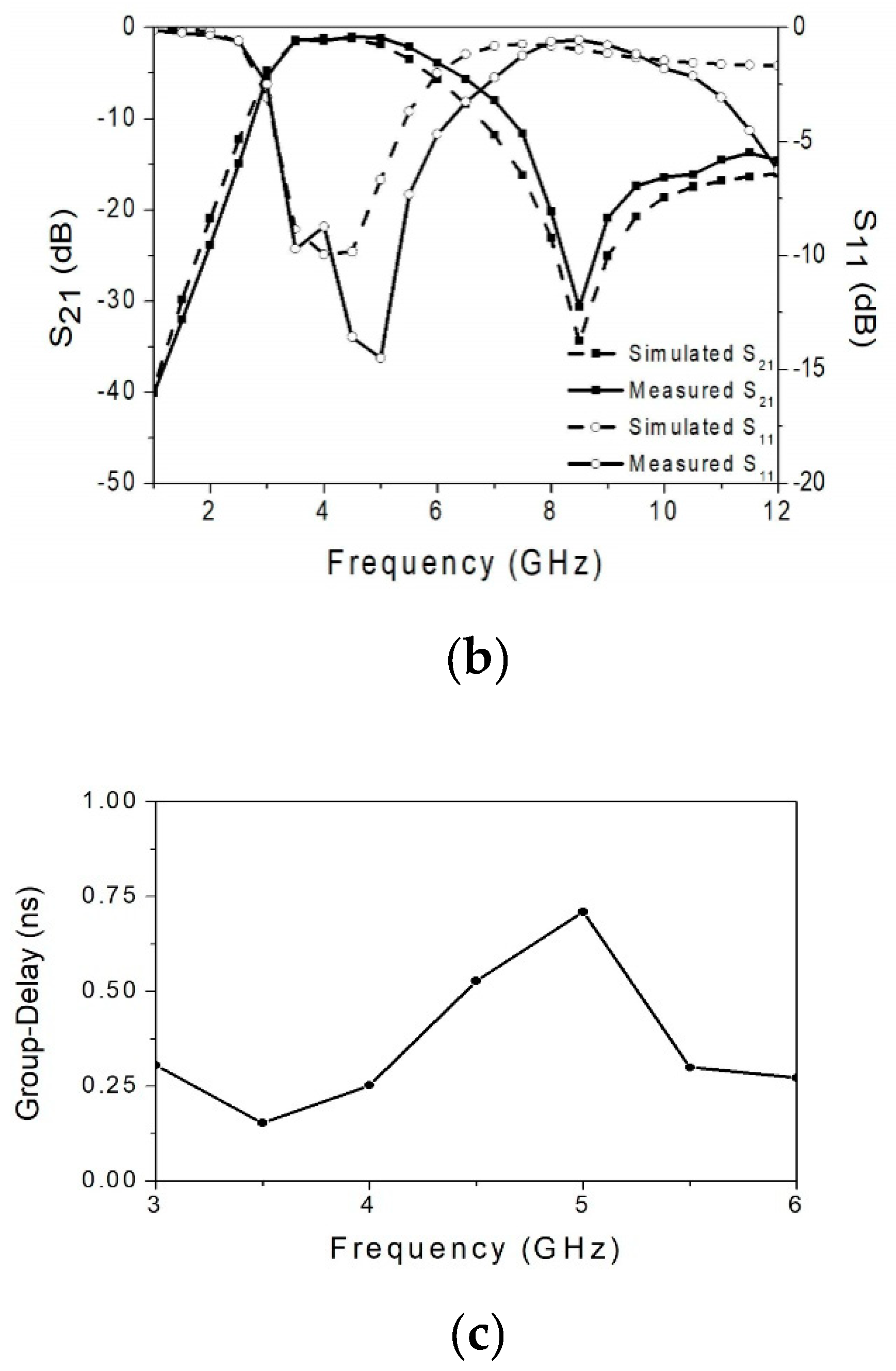
3. Experimental Results
4. Conclusions
Author Contributions
Funding
Acknowledgments
Conflicts of Interest
References
- Revision of Part 15 of the Commission’s Rules Regarding Ultra-Wideband Transmission Systems; ET-Docket 98-153, FCC02-48; Federal Communication Commission: Washington, DC, USA, 2002.
- Hong, J.S.; Lancaster, M.J. Microstrip Filters for RF/Microwave Applications; John and Wiley Sons: New York, NY, USA, 2001. [Google Scholar]
- Chang, D.C.; Hsue, C.W. Wide-band equal-ripple filters in nonuniform transmission lines. IEEE Trans. Microw. Theory Tech. 2002, 50, 1114–1119. [Google Scholar] [CrossRef]
- Hung, C.Y.; Weng, M.H.; Yang, R.Y.; Su, Y.K. Design of the parallel coupled wideband bandpass filters with very high selectivity and wide stopband. IEEE Microw. Wirel. Compon. Lett. 2007, 17, 510–5127. [Google Scholar] [CrossRef]
- Zhu, L.; Sun, S.; Menzel, W. Ultra-wideband (UWB) bandpass filters using multiple-mode resonator. IEEE Microw. Wirel. Compon. Lett. 2005, 15, 796–798. [Google Scholar]
- Li, R.; Zhu, L. Compact UWB bandpass filter using stub-loaded multiple-mode resonator. IEEE Microw. Wirel. Compon. Lett. 2007, 17, 40–42. [Google Scholar] [CrossRef]
- Killamsetty, V.K.; Mukherjee, B. Compact wideband bandpass filter for TETRA band applications. IEEE Microw. Wirel. Compon. Lett. 2017, 27, 630–632. [Google Scholar] [CrossRef]
- Wang, H.; Zhu, L.; Menzel, W. Ultra-wideband bandpass filter with hybrid microstrip/CPW structure. IEEE Microw. Wirel. Compon. Lett. 2005, 15, 844–846. [Google Scholar] [CrossRef]
- Ye, C.S.; Su, Y.K.; Weng, M.H.; Kuan, H.; Syu, J.J. Design of a compact CPW bandpass filter used for UWB application. Microw. Opt. Tech. Lett. 2009, 51, 298–300. [Google Scholar] [CrossRef]
- Chang, Y.C.; Kao, C.H.; Weng, M.H.; Yang, R.Y. Design of compact wideband bandpass filter using with low loss, high selectivity and wide stopband. IEEE Microw. Wirel. Compon. Lett. 2008, 18, 770–772. [Google Scholar] [CrossRef]
- Choudhary, D.K.; Chaudhary, R.K. A compact via-less metamaterial wideband bandpass filter using split circular rings and rectangular stub. Prog. Electromagn. Res. Lett. 2018, 72, 99–106. [Google Scholar] [CrossRef]
- Ji, X.C.; Ji, W.S.; Feng, L.Y.; Tong, Y.Y.; Zhang, Z.Y. Design of a novel multi-layer wideband bandpass filter with a notched band. Prog. Electromagn. Res. Lett. 2019, 82, 9–16. [Google Scholar] [CrossRef]
- Li, Z.; Wu, K.L. Direct synthesis and design of wideband bandpass filter with composite series and shunt resonators. IEEE Trans. Microw. Theory Technol. 2017, 65, 3789–3800. [Google Scholar] [CrossRef]
- Li, Y.; Choi, W.W.; Tam, K.W.; Zhu, L. Novel wideband bandpass filter with dual notched bands using stub-loaded resonators. IEEE Microw. Wirel. Compon. Lett. 2017, 27, 25–27. [Google Scholar]
- Gao, X.; Wen, F.; Che, W. Compact ultra-wideband bandpass filter with improved upper stopband. IEEE Microw. Wirel. Compon. Lett. 2007, 17, 643–645. [Google Scholar]
- Hameed, M.; Xiao, G.; Najam, A.I.; Qiu, L.; Hameed, T. Quadruple-mode wideband bandpass filter with improved out-of-band rejection. Electronics 2019, 8, 300. [Google Scholar] [CrossRef]
- Makimoto, M.; Yamashita, S. Bandpass filters using parallel coupled stripline stepped impedance resonators. IEEE Trans. Microw. Theory Tech. 1980, 28, 1413–1417. [Google Scholar] [CrossRef]
- Ye, C.S.; Su, Y.K.; Weng, M.H.; Hung, C.Y.; Tang, R.Y. Design of the compact parallel-coupled lines wideband bandpass filters using image parameter method. Prog. Electromagn. Res. 2010, 100, 153–173. [Google Scholar] [CrossRef]
- IE3D Simulator; Zeland Software, Inc.: Fremont, CA, USA, 2002.
- Tsai, C.M.; Lee, S.Y.; Tsai, C.C. Performance of a planar filter using a 0° feed structure. IEEE Trans. Microw. Theory Tech. 2002, 50, 2362–2367. [Google Scholar] [CrossRef]


| Ref. [11] | Ref. [12] | Ref. [13] | Ref. [14] | Ref. [15] | This Work | |
|---|---|---|---|---|---|---|
| Center frequency (GHz) | 2.3 | 3 | 2 | 2.3 | 1 | 4.2 |
| |S11| (dB) | 13 | 11.7 | 20 | >13 | 15 | 15 |
| |S21| (dB) | 0.35 | 2.1 | 0.57 | 0.35 | 1 | 1.2 |
| 3 dB FBW (%) | 80 | 107 | 100 | 80 | 123 | 55 |
| Circuit Size (λg × λg) | 0.12 × 0.22 | 0.89 × 0.46 | No description | 0.53 × 0.43 | 0.17 × 0.14 | 0.3 × 0.1 |
| Wide stopband | No | No | Yes | No | Yes | Yes |
| Defected ground | No | Yes | No | No | No | No |
© 2019 by the authors. Licensee MDPI, Basel, Switzerland. This article is an open access article distributed under the terms and conditions of the Creative Commons Attribution (CC BY) license (http://creativecommons.org/licenses/by/4.0/).
Share and Cite
Liu, L.; Zhang, P.; Weng, M.-H.; Tsai, C.-Y.; Yang, R.-Y. A Miniaturized Wideband Bandpass Filter Using Quarter-Wavelength Stepped-Impedance Resonators. Electronics 2019, 8, 1540. https://doi.org/10.3390/electronics8121540
Liu L, Zhang P, Weng M-H, Tsai C-Y, Yang R-Y. A Miniaturized Wideband Bandpass Filter Using Quarter-Wavelength Stepped-Impedance Resonators. Electronics. 2019; 8(12):1540. https://doi.org/10.3390/electronics8121540
Chicago/Turabian StyleLiu, Liqin, Ping Zhang, Min-Hang Weng, Chin-Yi Tsai, and Ru-Yuan Yang. 2019. "A Miniaturized Wideband Bandpass Filter Using Quarter-Wavelength Stepped-Impedance Resonators" Electronics 8, no. 12: 1540. https://doi.org/10.3390/electronics8121540
APA StyleLiu, L., Zhang, P., Weng, M.-H., Tsai, C.-Y., & Yang, R.-Y. (2019). A Miniaturized Wideband Bandpass Filter Using Quarter-Wavelength Stepped-Impedance Resonators. Electronics, 8(12), 1540. https://doi.org/10.3390/electronics8121540