Abstract
The number of wireless services and devices have remarkably increased, especially since the introduction of smart phones. The population of mobile nodes (MNs) is now exceeding the traditional non-mobile nodes. Mobility is a key factor in mobile core networks as it is responsible for providing continuous communication when a MN is on the move. Currently, a centralized mobile core network architecture is implemented, which has certain limitations. Distributed mobility management (DMM) is often seen as a solution to the problems associated with centralized mobility management (CMM). Address and tunneling management are big challenges for current DMM-based mobility protocols. Keeping in mind the current advancement of mobile network architecture, this paper proposes a novel tunnel-free distributed mobility management support protocol intended for such an evolution. In addition, the performance of the existing DMM IPv6 mobility management protocols in the context of handover latency, handover blocking probability, and data packet loss is analyzed and compared to the proposed framework. The performance analyses show that the proposed tunnel-free method can reduce about 12% of handover latency, 71% of handover blocking probability, and 82% of data packet loss.
1. Introduction
The advent of a huge plethora of wireless technologies have opened new opportunities besides the typical voice calling services. Wireless services and devices have seen a remarkable increase, especially since the introduction of smart phones. As reported in Sandvine [1], the population of mobile nodes now exceeds that of traditional wired nodes. With such an increase, the IP paradigm is now shifting from IPv4 to IPv6 as the IPv4 addresses are not enough. The current implementation of a mobile core network architecture is in a hierarchical and centralized manner. Therefore, the mobility management protocols, such as mobile IPv6 (MIPv6) and proxy mobile IPv6 (PMIPv6), have also been deployed in this manner [2,3]. More devices need more IP addresses, which results in the need for network scalability. A scalability issue has been identified as one of the limitations of the current centralized and hierarchical network architecture [4,5]. Other limitations include sub-optimal routing, central point of failure, and reliability problems.
Distributed mobility management (DMM) [5] is often seen as a solution to the scalability, reliability, central failure point, and routing issues of the centralized network architecture since the DMM approach distributes the responsibility of providing connectivity and mobility by going toward a flat network architecture. IP mobility support for such flat mobile network architectures is needed. Therefore, to address such architectural changes, the IETF (Internet Engineering Task Force) Distributed Mobility Management (DMM) working group was developed in March 2012 to manage the rapidly increasing mobile internet usage. IETF is making sure to deploy such DMM protocols that are not centrally deployed, but instead distributes mobile Internet traffic in an ideal way [6]. The problems and issues in centralized mobility management (CMM) can be overcome if effective mobility protocols are introduced in DMM.
The IETF standardized mobility management schemes for IPv6 are different variations of MIPv6 [2], which are further divided into two categories: network-based mobility protocols and client-based mobility protocols. The client-based mobility methods maintain session continuity through tunneling using a home agent (HA) as a mobility anchor and a mobile node (MN) as a signaling agent, e.g. MIPv6 and Dual Stack MIPv6 [7]. In contrast, network-based mobility methods maintain session continuity with tunneling using a local mobility agent (LMA) as a mobility anchor and a mobile access gateway (MAG) as a signaling agent, e.g. Proxy Mobile IPv6 (PMIPv6) [3]. In both these approaches, there are centralized entities, i.e. HA/LMA, they anchor the IP addresses used by the MN, and are responsible for maintaining mobility management.
Development of DMM faces some challenges as well [8]. The DMM approach allows an MN to keep more than one IP address simultaneously in the case of MN mobility. Hence, there is a need for proficient tunneling and IP address management. Second, additional IP addresses result in the increment of bi-directional tunnels, which in turn increases the signaling messages along with an additional registration delay. Another challenge regards network configuration and resource management since everything now has to be managed in a distributed fashion. Tunneling management is a big challenge for current DMM-based mobility protocols. This research will focus on this problem.
In this research, a tunneling-free design for mobility in a DMM was proposed in order to ensure seamless session continuity for MNs. In this design, session continuity of an MN on the move is ensured by using a make-before-break (MBB) approach. To ensure Quality of Service (QoS) to users, handover is to be performed in an MBB fashion, i.e., a new path reservation is made for an ongoing connection before switching its whole traffic onto the new path and tearing down the old path [9]. The handover takes place when an MN is in the overlapping region of the two base mobility agents (BMAs). Connections can be established to the two BMAs simultaneously, and in this manner, the MN can communicate with two BMAs. With the availability of more than one active connection through the handover process, this leads to a more seamless and reliable handover performance. Once the handover with the MBB is complete, the connection to the previous BMA is dropped, and the MN continues to communicate with the new BMA.
Since the establishment of the DMM working group in 2012, research is in progress that focuses on providing mobility management in a distributed manner. As DMM is yet to be standardized, substantial research [5,6,7,8,9,10,11,12,13,14,15,16,17,18,19,20,21,22] has been done in this area. DMM has been introduced as an architectural model to facilitate the surfacing mobile IP networks [5]. There is the need for a change to move toward more flat architectures from the current hierarchical trends. The standard-making bodies like IETF and 3GPP (3rd Generation Partnership Project) are developing designs to facilitate DMM needs and requirements. DMM approaches have been classified into client-based, network-based, and routing-based approaches. In the client-based approach, the existing suggestions plan on distributing the anchoring by installing more than one HA at the edge of an access network. If the MN is on the move, the previous session is maintained by tunneling and is forwarded to the care of address (CoA). Bi-directional tunnels are used to ensure session continuity between the MN and each HA. Tunneling and address management is one of the challenges of DMM, and there is a need for a more efficient tunneling mechanism, as well as the management of multiple IPs assigned to MN along the way.
Lee, J.H. et. al. [6] have discussed DMM from the perspective of IETF. They have discussed how the IETF DMM workgroup plans to distribute mobile internet traffic in an ideal way while deploying the mobility anchors in a distributed manner. They have discussed in detail the two possible DMM approaches, i.e., a host-based DMM approach and a network-based DMM approach, along with their comprehensive comparison. They have pointed out the four main challenges faced by DMM: address and tunneling management, registration delay and signaling overhead, network configuration and resource management, and security considerations. Lee, J.H. et al. [8] have proposed a DMM protocol for host-based IPv6 mobile networks. They have introduced an access mobility anchor at an access network level. Mobility signaling is handled by the MN itself. The MN is attended by its nearest mobility anchor. They have compared their design to MIPv6 in terms of throughput and handover delay. On the other hand, they have kept their analysis limited to only one mode of MIPv6, i.e., bi-directional tunneling, and they have not considered a MIPv6 route optimization mode. Giust, F. et al. [10] have discussed DMM architecture and deployment scenarios. Two types of deployment scenarios were given: network function virtualization and selected internet IP traffic offload/local IP access scenario in 3GPP. The first type suggests the separation of data and control planes. Mobility management is provided in two ways: mobility management functions with separate control and data planes under one controller, or with separate control and data planes with separate control in core and access networks. Ali-Ahmad et al. [11] have proposed a DMM design that offers global and local mobility support in a distributed fashion called distributed dynamic MIPv6. They have performed an analysis considering the mobility costs. Global mobility is ensured by keeping a record of the most recent session entry even after it is terminated.
Chan, H.A. et al. [12] have explored distributed and dynamic mobility management in the context of mobile internet. They have discussed the issues, challenges, and existing DMM approaches. They have highlighted the fact that DMM can address the CMM issues since its features are well-suited to the developing trends of mobile networks. Lee, J.H. et al. [13] have evaluated the performance of current IP mobility management protocols using an analytical cost model. The comparison parameters were the packet delivery cost, signaling cost, tunneling cost, and total cost. They have pointed out the weaknesses and strengths of each mobility protocol for use in a consumer network design. Lee, J.H. et al. [8] have evaluated the handover performance of current IP mobility management protocols. They analyzed the characteristics of handover operations in terms of handover delay, packet loss, and handover blocking probability. These characteristics can be used in the development of new mobility management protocols. Giust, F. et al. [14] have proposed a MIPv6 client-based DMM solution using cryptographic generated addresses. They called it flat access mobility architecture. Chan, H.A. et al. [15] have presented an architecture that unifies various possibilities of DMM. They proposed a method to co-locate the logical functions at the access router (AR) or gateway. Condeixa, T. et al. [16] have introduced a make-without-break concept during horizontal IP handovers in DMM. The handover is performed once the MN is in the overlapping area of the two access points (AP). A double MAC (Media Access Control) association is needed during the handover. DMM solutions are integrated with MAC layer handover approaches. This concept is called dynamic mobile IP anchoring. Lee, J.H. et al. [17] have discussed a host-based DMM approach with mobile data offloading. They have given a qualitative analysis highlighting the strength of their approach using a selective data offloading mechanism. In their proposed approach, an offloading system is built with distributed mobility anchors called offloading points. The MN maintains the binding updates and flow table.
Cominardi, L. et al [18] have provided a DMM framework based on PMIPv6 that makes use of software-defined networking (SDN). The authors have investigated and evaluated the two major DMM protocol groups: the SDN-based group and the IP-mobility group. They have designed and implemented protocols for both groups. They have also worked on breaking down the aspects that should exist in a DMM solution and how it could be implemented with an SDN solution. The major contribution of their research is an insight on the ways to apply DMM concepts in future mobile networks. Carmona-Murillo, J. [19] have proposed a hybrid DMM solution for future mobile networks. They have pointed out that there are cases where the DMM approach has not performed its best, which has compromised real-time and many over the top applications, in addition to increasing the signaling overhead in the network. The authors have analyzed the possibilities of different trade-offs between the centralized mobility architecture and DMM, in this way taking the best of both CMM and DMM and provided a hybrid solution based on it. According to their analysis, the hybrid solution performs well in terms of the packet delivery cost and signaling overhead. Huang, C.-M. et al. [20] have focused on the DMM handover issues when multiple MNs perform a handover rather than a single MN handover. They have proposed a solution to this problem by using partial DMM, proposing a bursty multi-node handover scheme. The technique that they have deployed is that instead of using multiple sets of control messages for a group of MNs, only one set of control messages is used for the handover. According to the authors, for exchanging handover signaling messages, their proposed scheme can decrease bandwidth consumption by 30%. Huang, C.-M et al. [21] have addressed the issue of overloaded AP or a mobility anchor and access router due to an increase in the number of MNs attaching to them. They have proposed mobile edge computing (MEC) as a solution to this issue. Their research introduces a MEC-assisted technique that facilitates early handovers using full DMM. Their proposition is to force a MN into performing an early handover by defining trigger-timing. Furthermore, to sidestep the unbalanced network, a decision is made regarding the MN suitable for early handovers. Fafolahan, E.M.O. et al. [22] have focused on the limited performance and increased cost issues of DMM protocols in the event of a short cell-residence time. They have proposed an approach that is based on fast handover concepts, locator identifier separation protocol, and local mobility anchoring for 5G dense small cells. The proposed technique splits up a local domain into many location service areas, where a local anchor controls each area. They have analyzed their protocol in terms of different handover parameters like handover latency, total signaling cost, packet loss, and data delivery cost, improving the performance of each parameter.
All these proposed DMM approaches have tried in their own way to provide mobility services to a MN in a distributed manner, proving that a distributed approach best suits the current mobile networks’ needs rather than the centralized approach. On the other hand, DMM also faces many challenges when it comes to practical deployment. One of the major challenges is managing tunneling when providing session continuity to a MN. With tunneling comes other problems as well, such as the management of multiple IPs, the registration delay and signaling overhead as a result of increasing tunnels, the network configuration and resource management, and some security considerations. All the DMM schemes discussed above use the concept of tunneling, and hence face the issues and problems mentioned above.
The main contributions of this research include the proposition of a framework that provides a tunnel-free DMM support protocol for mobile networks and then comparing it with the existing IPv6 mobility management protocols. The endorsement of a flat network architecture, as opposed to the hierarchical network architecture, is made to overcome the limitations of a centralized core network architecture. There is also no hassle in terms of tunnel management and address management. Endorsement of network scalability is done through a DMM approach. Lastly, communications and transmissions are made more seamless by mitigating the delays involved in the process, e.g., with no tunneling involved, there will not be additional registration delays. With the conducted analysis in this research, it confirms that the proposed tunnel-free DMM support protocol results in a considerably mitigated and reduced handover delay, which produces a reduced handover blocking probability and data packet loss.
2. Proposed Tunnel-Free DMM Support Protocol
This section introduces a novel tunnel-free DMM support protocol. It removes the MIPv6 limitations by making use of the current advancements in mobile network architectures.
2.1. Overview
At an access network level, the proposed DMM approach depends on distributed mobility anchors as follows:
• Base Mobility Agent (BMA): The HA of MIPv6 is expanded to a BMA. The BMA performs mobility and routing management for the MN. The network prefix is assigned to the MN by BMA. The MN is supplied by the BMA it is currently attached to. The architecture is distributed, and therefore multiple BMAs are deployed. For a MN on the move, it gets attached to another BMA in its range when it is about to leave the coverage area of the previous BMA. In this design, session continuity of a MN on the move is ensured by using the MBB approach. In traditional break-before-make infrastructures, only one connection can exist between a node and an access point. This requires nodes to continually break and re-establish connectivity as they move between access points. By using the incrementally evolved MBB [23,24] approach, a network can scan for and determine the next best available path prior to handoff. User data packets that go to and from the BMA and MN are transferred within a radio access network where the MN is currently connected. The handover control within the domain is focused on accommodating user mobility, while at the same time avoids interrupting or delaying ongoing user packets transfer, degrading the QoS of such a user packet transfer, or dropping user packets that should not be dropped. Therefore, the MBB approach is adopted, i.e., network resources at the target side are reserved prior to the movement of a MN to the target cell. Mechanisms used to reserve resources at the target side are carefully designed to ensure the success of the handover. During handover, BMAs may be relocated due to old BMAs that could not serve the MN. The handover takes place when the MN is in the overlapping region of the two BMAs. Connections can be established to the two BMAs simultaneously, and in this manner, the MN can communicate with two BMAs. The availability of more than one active connection through the handover process leads to a more seamless and reliable handover performance. The adjacent cells work on similar channels or frequencies that MBB uses for simultaneous connections, thus the MNs can communicate simultaneously with the old and new BMAs during the handover. Once the handover with MBB is complete, the new BMA informs the Corresponding Node (CN) about the MN’s updated path and the connection to the previous BMA is dropped. Once the MN is attached to the new BMA, a new address is assigned to it. If the MN has an unfinished, ongoing transmission session with the previous address, the previous address is maintained by the MN until the new address is completely configured. When the new address is completely configured, an IP handover takes place. The previous ongoing session is then continued on the newly configured address. The previous address is then discarded by the MN. The previous session, as well as the new session, will now be anchored through the new BMA.
Signaling Messages: There will be two separate signaling messages.
• Binding Update (BU) and Binding Acknowledgment (BA): The MN registers its movement to the current BMA through a BU message. The MN sends the BU message containing the new address configured at the current BMA and the previous address configured at the previous BMA. The current BMA then sends a binding acknowledgement (BA) message to notify the MN of the success or failure of its registration for each address.
• New Binding Update (NBU) and New Binding Acknowledgment (NBAck): The purpose of the NBU message is to update the MN’s mobility status from the previous BMA to the current BMA and to continue the previous ongoing session with the newly configured address. It should be noted that the NBU message is sent once the current BMA validates that the previous session has been linked to the new address. In response, a NBAck message is sent to the previous BMA from the current BMA.
The BMAs communicate with each other with the help of NBU and NBAck messages. The newly configured address is registered by the MN while the previous address is still valid. The address information is extracted by BMA2 upon receiving the NBU message, where the movement of the MN to BMA2 is updated with the help of this extracted information. The BMA2 then sends the NBAck message containing the newly configured address of MN to BMA1, indicating the complete configuration of the new address.
In the architecture, at the access network level, the BMAs are distributed. The address is assigned to the MN based on a network prefix provided by the BMA. Using the BU message, the MN then registers the assigned address with the BMA. When the MN on the move changes its attachment point to another BMA, the MN then configures a new address based on the network prefix provided at the new access network; however, it retains the previous address. Upon registration by a BU message, the MN informs the current BMA about the previous address along with the configuration of the new address. As the current BMA attains the previous address data from the BU message, it sends an NBU message to the previous BMA, which updates the mobility and routing status of the MN. The IP handover is confirmed by an NBAck. Figure 1 shows this scenario.
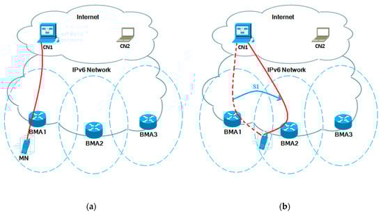
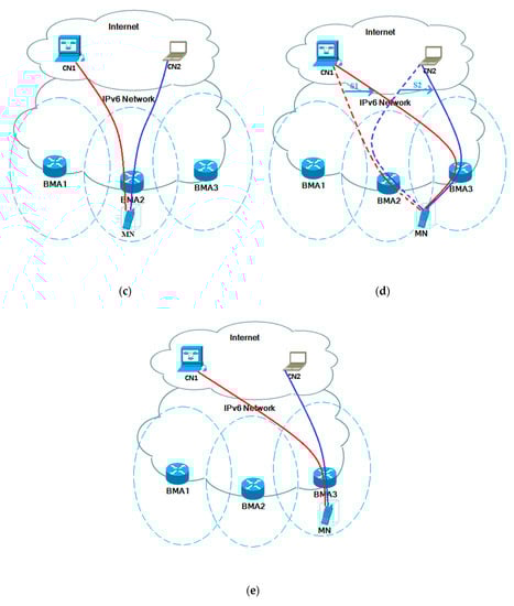
Figure 1.
Architecture of the proposed approach. (a) MN communicating with CN1 via BMA1. (b) MN on the move, handover initiated to BMA2. (c) Handover complete. Session 1 (S1) continued via BMA2, meanwhile establishing new session with CN2. (d) MN on the move, handover initiated towards BMA3. (e) Handover complete. Both sessions now continued via BMA3.
As discussed above, the proposed approach depends on distributed BMAs at the access network level, preventing a network bottleneck and avoiding a single point of failure. The proposed approach gives network scalability a fair chance, and it improves the performance of end-to-end packet transmission by removing the tunneling tradition and making use of the MBB.
2.2. Protocol Operation
The steps of the protocol operation of proposed approach, as shown in Figure 2 are as follows:
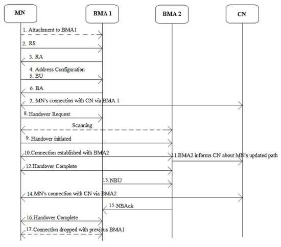
Figure 2.
Handover operation of the proposed approach. BA: binding acknowledgment, BU: binding update, NBAck: new binding acknowledgment, NBU: new binding update, RA: router advertisement, RS: router solicitation.
- Connection to BMA1.
- (RS) Router solicitation notification to BMA1.
- (RA) Router advertisement notification.
- Address configuration
- BU notification to BMA1.
- BA notification to MN.
- MN connected with CN for communication via BMA1.
- Handover requested by MN from BMA1.
- Handover initiated after scanning and finding BMA2.
- MN’s connection established with BMA2.
- BMA2 informs the CN about the MN’s updated path.
- BMA2 informed of handover completion.
- NBU from BMA1 to BMA2.
- MN’s connection with CN via BMA2
- NBAck from BMA2 to BMA1.
- BMA1 informed of handover completion.
3. Analytical Modeling and Performance Evaluation
A mathematical analysis was performed to evaluate the performance of tunnel-free MIPv6 with MIPv6, PMIPv6, FMIPv6, and HMIPv6 in terms of the handover latency, handover blocking probability, and data packet loss.
3.1. Network Topology
The network topology for performance evaluation is presented in Figure 3. The proposed tunnel-free protocol with DMM was assessed with other protocols. Since for MIPv6 and PMIPv6, there exists no benchmark deployment model [25], we assumed that BMA was in the similar point as the AR and MAG in MIPv6 and PMIPv6, respectively. In this situation, distance dHA-AR was considered to be larger than dMAG-LMA.
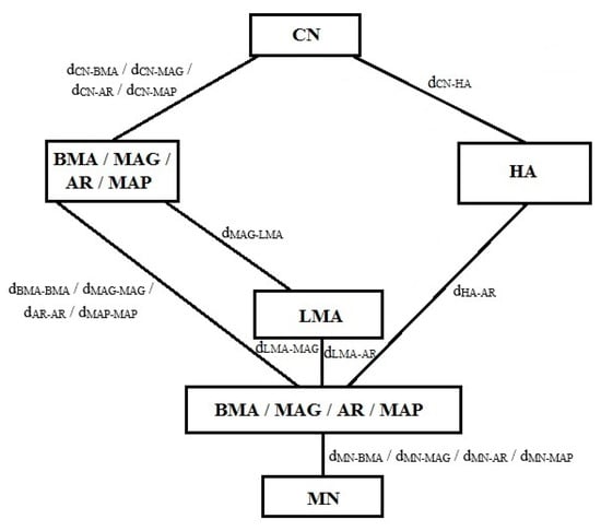
Figure 3.
Network topology for performance evaluation. AR: access router, LMA: local mobility agent, MAG: mobile access gateway, MAP: mobility anchor point.
Parameters and notations used,
- dL2: handover delay of link layer depending on the chipset implementation for a wireless interface.
- dA: link layer authentication latency.
- dMD: movement detection process delay.
- dDAD: duplicate address detection delay.
- dN: new binding update and acknowledgement process delay.
- dR: delay of proposed protocol’s handover registration.
- dS: arrival delay of first packet of previous session from current BMA to the MN.
- mRS, mRA: RS/RA message size = 52, 80 bytes.
- mBU, mBA: BU/BA message size = 56, 56 bytes.
- mNBU, mNBAck: NBU/NBAck message size = 56, 56 bytes.
- mD: data packet size = 1 kbytes.
- mM: mobility option for an address bound to the MN = 20 bytes.
- bWL: bandwidth of wireless link.
- tWL: propagation time for the wireless link.
- bWD: bandwidth of wired link.
- tWD: propagation time for the wired link.
- pf: link failure probability over wireless link.
- d: the number of hops between the CN and current BMA.
- S(L): average session length in data packet.
- i: inter-packet time.
3.2. Modeling the Handover Latency
3.2.1. Handover Latency of MIPv6
IETF developed MIPv6 at the network layer for handling mobility management. It keeps an MN accessible while it is on the move within the IPv6 network. A home address (HoA) identifies its MN regardless of its present point of connection to the network. The MN is linked with a care-of-address (CoA), as well as when it is away from its home domain. The MN uses mobility signaling messages to register the CoA with the HA. The packets received by the HoA for the MN are then routed to the MN’s CoA. The handover latency of MIPv6 in this case can be given as [26]:
where LHO represents the handover latency, TL2 is the link layer handover latency, TDAD is the duplicate address detection latency, and TR is for registration latency.
3.2.2. Handover Latency of FMIPv6
FMIPv6 arranges for a CoA beforehand in association with the new access router (nAR) with the help of L2 triggers. It then creates a bi-directional tunnel amid the new access router (nAR) and the old access router (oAR) to reduce the handover latency. Upon connection with the new link, the MN informs the nAR that packets can now be received. Once the MN successfully obtains the FBAck (Fast Binding Acknowledgement) message that has been sent by the oAR before moving to the nAR, predictive FMIPv6 is executed; otherwise, reactive FMIPv6 is performed. The handover latency for predictive FMIPv6 can be given as [27]:
where TPRE represents the time the time at which the nAR receives the Unsolicited Neighbor Advertisement (UNA) message sent from the MN and the time at which the MN receives the first data packet sent from the nAR. TL2 is the link layer handover latency.
The handover latency for reactive FMIPv6 can be given as [8]:
where TR is for registration latency, TDAD is the duplicate address detection latency and TRE represents the time to send FBU (Fast Binding Update) message, exchange required information between the relevant ARs and receives the first data packet sent from the nAR.
3.2.3. Handover Latency of HMIPv6
MIPv6 makes the MN exchange mobility messages with the HA/CN and configure a new CoA whenever the MN is on the move. In the case where the distance between the MN and HA/CN is large, it becomes very time consuming and also results in unnecessary signaling overhead. HMIPv6 [28] addresses this problem by introducing a MAP (mobility anchor point), a new functional entity for local mobility management. The handover latency for HMIPv6 can be given as:
where TL2 is the link layer handover latency, TMD is the movement detection process delay, TDAD is the duplicate address detection latency and TMAP represents the time required to send the binding update message, receive the binding acknowledgement message and also receive the data packet sent from the MAP.
3.2.4. Handover Latency of PMIPv6
The MN on the move is managed in a localized manner in PMIPv6. The entities providing a mobility service supports the mobility for the MN. The mobile access gateway (MAG) senses and registers the movement of the MN when it gets attached to a new access network. For a handover in the domain of PMIPv6, the Duplicate Address Detection (DAD) process and address configuration is not compulsory since the same home network prefix in the RA message sent from the MAG at the new access network is obtained by the MN. The handover latency for PMIPv6 can be given as [29]:
where TLMA includes the time needed to receive the LMA’s first data packet, time needed to send the RS message, and the time needed to exchange the update and acknowledgement messages between the LMA and MAG.
3.2.5. Handover Latency of Proposed Approach
The handover latency for MIPv6 is found using Equation (1). For our proposed approach, as shown in the handover timing diagram in Figure 4, the handover latency is comprised of the handover delay of link layer depending on the chipset implementation for a wireless interface (dL2), the link layer authentication latency (dAU), the movement detection process delay (dMD), the duplicate address detection delay (dDAD), the new binding update and acknowledgement process delay (dN), the delay of the proposed protocol’s handover registration (dR), and the arrival delay of the first packet of the previous session from the current BMA to the MN (dS). The delay in the movement detection process (dMD) is comprised of the time required for sending the RS notification and receiving the RA notification. If tRS denotes the time required for the RS notification, and tRA denotes the time required for the RA notification, then movement detection process delay dMD can be calculated using:
where TRS is the time required for sending the RS notification and receiving the RA notification and TR is the handover registration delay.
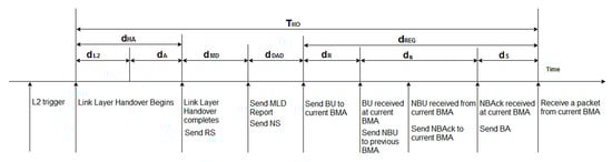
Figure 4.
Handover timing diagram for the proposed approach.
The factors involved in the delay in the RS/RA notification are the message size of RS/RA, the bandwidth and propagation time of the wireless link, and the link failure probability of the wireless link. The RS/RA delay has been calculated according to the AR involved [9,30]. We derived tRS and tRA for our proposed approach focusing on the factors involved as mentioned above. tRS and tRA can then be calculated using:
In Figure 4, dR specifies the proposed protocol’s handover registration delay. It begins with the BU notification. For the proposed approach we derived dR as follows:
The proposed approach eliminates the need for tunneling by anchoring the sessions via a new BMA using the MBB approach. Let dN represent the new binding update and acknowledgement latency caused while sending a signaling message. Then, dN consists of a new binding update represented by dNBU and a new binding acknowledgement represented by dNBAck. We can calculate dN using:
The proposed approach also provides a mobility option for an address bound to the MN. It is represented by mM. Adding this factor to dN, dNBU and dNBAck can be calculated as follows:
The arrival delay of the first packet of the previous session from the current BMA to the MN is represented by dS. It involves a BA and the data packet represented by mD. We calculated dS as follows:
As can be seen in Figure 4, the overall registration delay is represented by dREG. Hence, it can be given as:
Meanwhile, the combined latencies of link layer handover and authentication can be given as:
Let THO denote the handover latency combining all the factors mentioned above. We can now calculate the handover latency for the proposed approach by summing up the involved timing factors as follows:
where the default values used for dL2, dA, dWRS, and dDAD are the same as in References [8,30].
3.2.6. Handover Latency Analysis
If the different handover latencies are compared, the order of latencies can be given as [31]:
When comparing HMIPv6 and PMIPv6, the order of latencies can be given as [32]:
When comparing PMIPv6 and FMIPv6, FMIPv6 outperforms PMIPv6 [33]. Therefore, we can say:
Our evaluation above shows that TFMIPv6 outperforms other mobility management protocols. Therefore, we can give the order of latencies as follows:
For comparison purposes, the relative gain is defined here for the handover latency to the MIPv6 process as:
where LHO is the handover latency for MIPv6 and THO is the handover latency for the proposed approach. If GH is greater than 0.1, signifies that the proposed handover technique outperforms the basic one.
MIPv6 > FMIPv6 > HMIPv6.
HMIPv6 > PMIPv6.
FMIPv6 > PMIPv6.
MIPv6 > FMIPv6 > HMIPv6 > PMIPv6 > TFMIPv6.
3.3. Handover Blocking Probability
3.3.1. Handover Blocking Probability of the Proposed Approach
For the proposed approach, the handover blocking probability presented in References [8,30,31,32] is used to examine the failures in terms of the handover blocking probability in this study. Many factors can cause a handover failure for the MN, such as the non-availability of a wireless network resource, signal-to-noise deterioration, and handover latency. If THO represents the handover latency for the proposed approach, let E[THO] denote the mean value of THO. Let TE be the time when MN exists in the network along with its probability density function ƒE(t). We assumed THO to be exponentially distributed with the cumulative function FT (t) for the sake of simplicity. If THO is the only factor blocking the handover, then the handover blocking probability pb is given as:
where µc is the rate of boundary crossing for the MN, i.e., its mobility rate. Supposing that the BMA’s coverage area is circular, then µc is calculated as follows [8,32,33,34]:
where v represents the average velocity of the MN and R represents the radius of the BMA’s coverage area.
3.3.2. Handover Blocking Probability Analysis with Other Approaches
Suppose the handover latency of a particular mobility management protocol is denoted by LHO(.), where (.) specifies a specific protocol. If the mean value of LHO(.) is given by E[LHO(.)] and the residence time in the network is denoted by TR, along with its probability density function ƒR(t). Supposing the handover latency is exponentially distributed along with the cumulative function FT(.)(t), for all other protocols with their respective handover latencies, the handover blocking probability can be calculated using:
where µc is the rate of boundary crossing of the MN, i.e., its mobility rate. Supposing that the BMA’s coverage area is circular, then µc is calculated with Equation (19) [8,32,33,34].
3.4. Data Packet Loss
3.4.1. Data Packet Loss with the Proposed Approach
During the handover process, upon the absence of a buffer management technique deployed at the network, the data packets sent to the MN might get lost. The total data packet lost during a handover process can be defined as the sum of all the lost data packets sent from a CN to the MN. Let δP represent the total data packet loss, which can be calculated using:
where λS represents the average session arrival rate at the MN’s wireless interface, S(L) represents the average session length in packets, and THO is the handover latency for the proposed approach.
3.4.2. Data Packet Loss Analysis with Other Approaches
Let φp(.) represent the total data packet loss for any protocol, which can be calculated as follows [8,32]:
where λS represents the average session arrival rate at the MN’s wireless interface, E[S] represents the average session length in packets, and LHO is the handover latency for a specific approach.
4. Results and Discussion
This section provides the results of the performance evaluation of the mobility management protocols in comparison with the proposed tunnel-free distributed mobility management approach. NS2 is chosen as the simulation platform for this research. Network Simulator 2.33 (NS2.33) [35] was used to investigate the proposed framework, along with Mobiwan, which is an extension tool for MIPv6. Mobiwan running on NS2.33 was installed on CentOs Linux 7 (a linux based operating system). Network Animator NAM 1.15 [36] was used for the NS2.33 simulation. Xgraph was used to generate the simulated results. For comparison purposes, system parameter values for the numerical analysis were used from References [30,37,38,39].
4.1. Handover Latency
Handover latency versus ρƒ is given in Figure 5, where ρƒ varied from 0 to 0.7 with a step value of 0.05. The likelihood of an erroneous packet transmission increased with a greater value of ρƒ on the wireless link. This in turn raised the number of retransmissions of mobility signaling, resulting in a larger handover delay. Consequently, as shown in Figure 5, the handover latency was relative to ρƒ for each mobility management protocol.
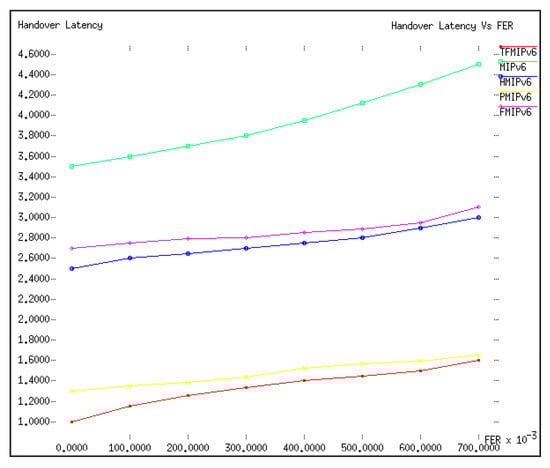
Figure 5.
Handover latency versus ρƒ.
In this analysis the proposed tunnel-free MIPv6 outperformed the other mobility management protocols in terms of handover latency due to the reason that the MN in the protocol utilized a tunnel-free approach and prepared its handover beforehand at the previous BMA before it actually moved to the new BMA. This analysis placed PMIPv6 second in terms of handover latency. PMIPv6 managed its MN locally. The LMA and MAG exchanged the mobility signaling, hence there was no need to perform the mobility signaling upon a wireless link leading to the minimized effect of ρƒ in the performance of PMIPv6.
4.2. Handover Blocking Probability
For comparison purposes, the values of velocity v and radius R were set to 20 m/s and 500 m, respectively, whereas the value of ρƒ varied from 0 to 0.7 with a step value of 0.05. Figure 6 shows the handover blocking probability for each mobility management protocol. For this analysis, the handover latency was considered as a blocking factor for the handover blocking probability. Synonymous with the previous result in Figure 5, an increase in the value of ρƒ consequently increased the handover blocking probability. The handover blocking probability of the proposed TFMIPv6 was lower than all the other protocols, while that of MIPv6 was higher than all the other protocols. Again, this analysis placed PMIPv6 second in terms of the handover blocking probability.
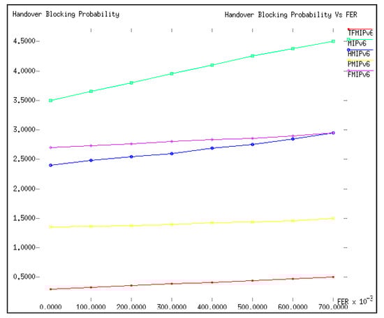
Figure 6.
Handover blocking probability versus ρƒ.
For comparison purposes, the values of ρƒ and R were set as 0.2 and 500 m, respectively, whereas the value of v varied from 0 to 30 m/s. Figure 7 shows the handover blocking probability versus v. With an increase in v, there were frequent changes in the MN’s point of attachment, which implied that it was necessary for a MN with a higher velocity to complete its handover in less time than the MN with a lower velocity. Therefore, the increase in the velocity consequently increased the handover blocking probability for each mobility management protocol. In the simulation, the proposed TFMIPv6 outperformed the other mobility management protocols in terms of the handover blocking probability, which was below 0.05 even with an increase in velocity up until 30 m/s. PMIPv6 again placed second in terms of the handover blocking probability with a value below 0.1 when the velocity reached 30 m/s. Synonymous with the earlier results, MIPv6 performed poorly yet again in terms of the handover blocking probability.
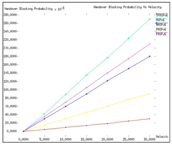
Figure 7.
Handover blocking probability versus v (m/s).
Furthermore, for comparison purposes, the values of ρƒ and v were set to 0.2 and 20 m/s, respectively, whereas the value of R varied from 400 to 800 m. The handover blocking probability versus R is shown in Figure 8. An increase in the value of R meant a bigger access network for the MN, which consequently increased the residence time for a MN to stay in that access network, giving the MN more time to complete its handover process, hence decreasing the handover blocking probability. As can be seen in Figure 8, R influenced most of the mobility management protocols but not the proposed TFMIPv6.
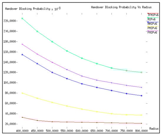
Figure 8.
Handover blocking probability versus R (m).
All the results presented in Figure 6, Figure 7 and Figure 8 show that the handover latency of the proposed TFMIPv6 was minor enough to not to be influenced and affected by the handover blocking problems caused by ρƒ, v, and R. The reason for the extraordinary performance of the proposed TFMIPv6 in comparison with the other protocols was the tunnel-free approach introduced, along with the MBB approach discussed earlier. The MBB approach allowed the MN to prepare its handover at the previous BMA before the MN performed the actual handover to the new BMA, meanwhile continuing the previous ongoing session anchoring through the new BMA instead of the previous BMA, hence eliminating the need for tunneling.
4.3. Data Packet Loss
During a handover process, data packets sent from the CN to MN tend to get missing. Figure 9 depicts the packet loss in the course of the handover process. For comparison purposes, the values of λS and E(S) were set to 1 and 10, respectively, whereas the value of ρƒ varied from 0 to 0.7. As can be seen in Figure 9, the proposed TFMIPv6 had the lowest amount of data packet loss when compared to other protocols. It was observed from the previous section that the handover latency was directly proportional to the packet loss during the handover process. To illustrate, MIPv6 took more time to complete its handover process, which resulted in more packet loss in contrast with the other protocols. The proposed TFMIPv6 outperformed the rest of the protocols in terms of data packet loss because it had the lowest handover latency.
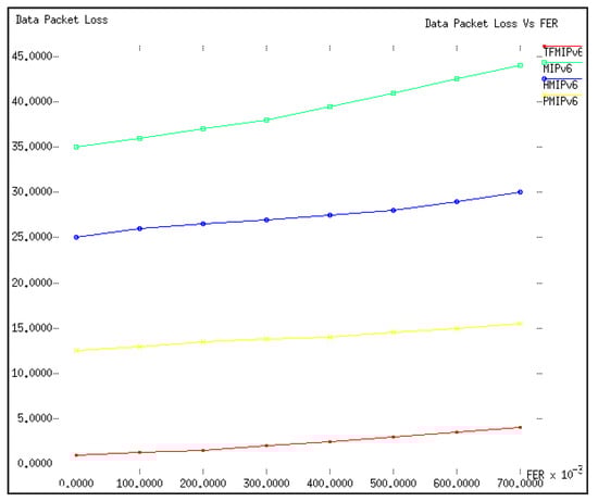
Figure 9.
Packet loss versus ρƒ.
5. Conclusions
This paper proposed a tunnel-free mobile IPv6 protocol using a DMM approach. In addition, it analyzed and compared the existing IPv6 mobility management protocols in terms of the handover latency, handover blocking probability, and packet loss. From the results of the analysis conducted, it was confirmed the proposed tunnel-free approach with MBB concept allowed an MN to prepare for the handover beforehand, and anchored the transmission from the current BMA instead of tunneling it from the previous BMA, avoiding a reduced handover delay, consequently reducing the handover blocking probability and data packet loss.
6. Future Work
Like most of the DMM-based protocols proposed, our work also focused on a single MN’s handover. In future work, to further improve the dimensions of the proposed research, we will be focusing on the DMM handover issues when multiple MNs perform a handover from the same previous network to the same destination network simultaneously, rather than a single MN handover. Moreover, we are also currently analyzing the cost of the proposed approach. In future work, we intend to compare the proposed approach in terms of cost with the benchmark protocols. In addition, we also intend to undertake a performance evaluation with other mobile IPv6-based schemes using the MBB approach. We have considered this aspect in the future work for this research. For now, we have performed performance evaluations with current existing deployed protocols for mobility management.
Author Contributions
Conceptualization, M.A., S.M. and M.Z.; Data Curation, M.A.; Formal Analysis, M.A., M.Z., N.M., K.I.; Investigation, M.A., S.M., M.Z., N.M.; Methodology, M.A., M.Z. and S.K.; Validation, M.A., S.M., M.Z.; Resources, M.A., M.Z.; Simulation, M.A., M.Z., K.I.; Writing—Original Draft Preperation, M.A., S.M., M.Z., N.M., K.I.; Writing—Review and Editing, M.A., S.M., M.Z., S.K.; Supervision, S.M.; Co-Supervision, M.Z.
Funding
This research received no external funding.
Conflicts of Interest
The authors have no conflict of interest to declare.
References
- Sandvine, I. The Mobile Internet Phenomena Report Febrauy 2019; Sandvine Inc.: Fremont, CA, USA, 2019. [Google Scholar]
- Perkins, C.; Johnson, D.; Arkko, J. RFC 6275: Mobility Support in IPv6; Internet Engineering Task Force (IETF): Fremont, CA, USA, 2011. [Google Scholar]
- Gundavelli, S.; Leung, K.; Devarapalli, V.; Chowdhury, K.; Patil, B. Rfc 5213: Proxy Mobile Ipv6; IETF: Fremont, CA, USA, 2008. [Google Scholar]
- Chan, H.; Liu, D.; Seite, P.; Yokota, H.; Korhonen, J. Rfc 7333: Requirements for Distributed Mobility Management, IETF. 2014. Available online: https://www.rfc-editor.org/rfc/rfc7333.txt (accessed on 14 May 2017).
- Zuniga, J.C.; Bernardos, C.J.; De La Oliva, A.; Melia, T.; Costa, R.; Reznik, A. Distributed Mobility Management: A Standards Landscape. IEEE Commun. Mag. 2013, 51, 80–87. [Google Scholar] [CrossRef]
- Lee, J.H.; Bonnin, J.M.; Seite, P.; Chan, H.A. Distributed IP mobility management from the perspective of the IETF: Motivations, requirements, approaches, comparison, and challenges. IEEE Wirel. Commun. 2013, 20, 159–168. [Google Scholar] [CrossRef]
- Soliman, H. RFC 5555: Mobile IPv6 support for dual stack hosts and routers. 2009, pp. 1–40. Available online: https://tools.ietf.org/html/rfc5555 (accessed on 11 December 2019).
- Lee, J.H.; Bonnin, J.M.; You, I.; Chung, T.M. Comparative handover performance analysis of IPv6 mobility management protocols. IEEE Trans. Ind. Electr. 2012, 60, 1077–1088. [Google Scholar]
- Jaumard, B.; Duong, H.Q.; Armolavicius, R.; Morris, T.; Djukic, P. Efficient real-time scalable make-before-break network re-routing. IEEE/OSA J. Opt. Commun. Netw. 2019, 11, 52–66. [Google Scholar] [CrossRef]
- Giust, F.; Bernardos, C.J.; Figueiredo, S.; Neves, P.; Melia, T. A hybrid MIPv6 and PMIPv6 distributed mobility management: The MEDIEVAL approach. In Proceedings of the 2011 IEEE Symposium on Computers and Communications (ISCC), Kerkyra, Greece, 28 June–1 July 2011. [Google Scholar]
- Ali-Ahmad, H.; Ouzzif, M.; Bertin, P.; Lagrange, X. Distributed dynamic mobile IPv6: Design and evaluation. In Proceedings of the 2013 IEEE Wireless Communications and Networking Conference (WCNC), Shanghai, China, 7–10 April 2013. [Google Scholar]
- Chan, H.A.; Yokota, H.; Xie, J.; Seite, P.; Liu, D. Distributed and dynamic mobility management in mobile internet: Current approaches and issues. JCM 2011, 6, 4–15. [Google Scholar] [CrossRef][Green Version]
- Lee, J.H.; Ernst, T.; Chung, T.M. Cost analysis of IP mobility management protocols for consumer mobile devices. IEEE Trans. Consum. Electr. 2010, 56, 1010–1017. [Google Scholar] [CrossRef]
- Giust, F.; de la Oliva, A.; Bernardos, C.J. Flat access and mobility architecture: An IPv6 distributed client mobility management solution. In Proceedings of the 2011 IEEE Conference on Computer Communications Workshops (INFOCOM WKSHPS), Shanghai, China, 10–15 April 2011. [Google Scholar]
- Chan, H.A. Distributed mobility management with mobile IP. In Proceedings of the 2012 IEEE International Conference on Communications (ICC), Ottawa, ON, Canada, 10–15 June 2012. [Google Scholar]
- Condeixa, T.; Guardalben, L.; Gomes, T.; Sargento, S.; Sofia, R. Make-without-break horizontal IP handovers for Distributed Mobility Management schemes. In Proceedings of the 2013 IEEE Globecom Workshops (GC Wkshps), Atlanta, GA, USA, 9–13 December 2013. [Google Scholar]
- Lee, J.H.; Singh, K.D.; Bonnin, J.M.; Pack, S. Mobile data offloading: A host-based distributed mobility management approach. IEEE Internet Comput. 2013, 18, 20–29. [Google Scholar] [CrossRef]
- Cominardi, L.; Giust, F.; Bernardos, C.J.; De La Oliva, A. Distributed mobility management solutions for next mobile network architectures. Comput. Netw. 2017, 121, 124–136. [Google Scholar] [CrossRef]
- Carmona-Murillo, J.; Friderikos, V.; González-Sánchez, J. A hybrid DMM solution and trade-off analysis for future wireless networks. Comput. Netw. 2018, 133, 17–32. [Google Scholar] [CrossRef]
- Huang, C.-M.; Dao, D.-T.; Chiang, M.-S. A Bursty Multi-node Handover scheme for mobile internet using the partially Distributed Mobility Management (BMH–DMM) architecture. Telecommun. Syst. 2018, 69, 113–130. [Google Scholar] [CrossRef]
- Huang, C.-M.; Dao, D.-T.; Chiang, M.-S. A MEC-Assisted Method for Early Handover Using the Fully Distributed Mobility Management (MEC-F-DMM) Architecture. In International Conference on Advanced Information Networking and Applications; Springer: Berlin, Germany, 2019. [Google Scholar]
- Fafolahan, E.M.O.; Pierre, S. A Seamless Mobility Management Protocol in 5G Locator Identificator Split Dense Small Cells. IEEE Trans. Mob. Comput. 2019. [Google Scholar] [CrossRef]
- Ramachandran, K.; Rangarajan, S.; Lin, J.C. Make-before-break mac layer handoff in 802.11 wireless networks. In Proceedings of the 2006 IEEE International Conference on Communications, Istanbul, Turkey, 11–15 June 2006. [Google Scholar]
- Wishart, R.; Portmann, M.; Indulska, J. Evaluation of wireless mesh network handoff approaches for public safety and disaster recovery networks. In Proceedings of the 2008 Australasian Telecommunication Networks and Applications Conference, Adelaide, SA, Australia, 7–10 December 2008. [Google Scholar]
- Jeon, S.; Kang, N.; Corujo, D.; Aguiar, R.L. Comprehensive performance evaluation of distributed and dynamic mobility routing strategy. Comput. Netw. 2015, 79, 53–67. [Google Scholar] [CrossRef]
- Xie, G.; Chen, J.; Zheng, H.; Yang, J.; Zhang, Y. Handover latency of MIPv6 implementation in Linux. In Proceedings of the IEEE GLOBECOM 2007-IEEE Global Telecommunications Conference, Washington, DC, USA, 26–30 November 2007. [Google Scholar]
- Ivov, E.; Montavont, J.; Noel, T. Thorough empirical analysis of the IETF FMIPv6 protocol over IEEE 802.11 networks. IEEE Wirel. Commun. 2008, 15, 65–72. [Google Scholar] [CrossRef]
- Castelluccia, C. HMIPv6: A hierarchical mobile IPv6 proposal. ACM Sigmob. Mob. Comput. Commun. Rev. 2000, 4, 48–59. [Google Scholar] [CrossRef]
- Udugama, A.; Iqbal, M.U.; Toseef, U.; Goerg, C.; Fan, C.; Schlaeger, M. Evaluation of a network based mobility management protocol: PMIPv6. In Proceedings of the VTC Spring 2009-IEEE 69th Vehicular Technology Conference, Barcelona, Spain, 26–29 April 2009. [Google Scholar]
- Yang, S.; Zhou, H.; Qin, Y.; Zhang, H. SHIP: Cross-layer mobility management scheme based on Session Initiation Protocol and Host Identity Protocol. Telecommun. Syst. 2009, 42, 5–15. [Google Scholar] [CrossRef]
- McNair, J.; Akyildiz, I.F.; Bender, M.D. An inter-system handoff technique for the IMT-2000 system. In Proceedings of the IEEE INFOCOM 2000. Conference on Computer Communications. Nineteenth Annual Joint Conference of the IEEE Computer and Communications Societies (Cat. No. 00CH37064), Tel Aviv, Israel, 26–30 March 2000. [Google Scholar]
- Makaya, C.; Pierre, S. An analytical framework for performance evaluation of IPv6-based mobility management protocols. IEEE Trans. Wirel. Commun. 2008, 7, 972–983. [Google Scholar] [CrossRef]
- Lee, J.-H.; Chung, T.-M. How much do we gain by introducing route optimization in Proxy Mobile IPv6 networks? Ann. Telecommun. 2010, 65, 233–246. [Google Scholar] [CrossRef]
- Zhang, X.; Castellanos, J.G.; Campbell, A.T. P-MIP: Paging extensions for mobile IP. Mob. Netw. Appl. 2002, 7, 127–141. [Google Scholar] [CrossRef]
- Issariyakul, T.; Hossain, E. Introduction to network simulator 2 (NS2). In Introduction to network simulator NS2; Springer: Boston, MA, USA, 2009; pp. 1–18. [Google Scholar]
- Meeneghan, P.; Delaney, D. An introduction to NS, Nam and OTcl scripting; National University of Ireland: Galway, Ireland, 2004. [Google Scholar]
- Banerjee, N.; Wu, W.; Das, S.K. Mobility support in wireless Internet. IEEE Wirel. Commun. 2003, 10, 54–61. [Google Scholar] [CrossRef]
- Han, Y.-H.; Min, S.-G. Performance analysis of hierarchical mobile IPv6: Does it improve mobile IPv6 in terms of handover speed? Wirel. Personal Commun. 2009, 48, 463–483. [Google Scholar] [CrossRef]
- Pack, S.; Choi, J.; Kwon, T.; Choi, Y. Fast-handoff support in IEEE 802.11 wireless networks. IEEE Commun. Surv. Tutor. 2007, 9, 2–12. [Google Scholar] [CrossRef]
© 2019 by the authors. Licensee MDPI, Basel, Switzerland. This article is an open access article distributed under the terms and conditions of the Creative Commons Attribution (CC BY) license (http://creativecommons.org/licenses/by/4.0/).