Article

Radar Waveform Optimization for Joint Radar Communications Performance

by
Alex R. Chiriyath
1,*,†,‡,
Shankarachary Ragi
2,‡,
Hans D. Mittelmann
3,‡ and
Daniel W. Bliss
1,‡
1
Bliss Laboratory of Information, Signals, and Systems and the Center for Wireless Information Systems and Computational Architectures (WISCA), Arizona State University, Tempe, AZ 85287, USA
2
Department of Electrical Engineering, South Dakota School of Mines and Technology, Rapid City, SD 57701, USA
3
School of Mathematical and Statistical Sciences, Arizona State University, Tempe, AZ 85287, USA
*
Author to whom correspondence should be addressed.
Current address: 650 E Tyler Mall, GWC 314, Tempe, AZ 85287, USA.
These authors contributed equally to this work.
Electronics 2019, 8(12), 1498; https://doi.org/10.3390/electronics8121498
Submission received: 15 November 2019 / Revised: 2 December 2019 / Accepted: 3 December 2019 / Published: 7 December 2019
(This article belongs to the Special Issue Cooperative Communications for Future Wireless Systems)

Abstract

:
We develop and present a radar waveform design method that optimizes the spectral shape of the radar waveform so that joint performance of a cooperative radar communications system is maximized. The continuous water-filling (WF) spectral-mask shaping method presented in this paper is based on the previously derived spectral-mask shaping technique. However, the method presented in this paper is modified to utilize the continuous spectral water-filling algorithm to improve communications performance. We also introduce additional practical system constraints on the autocorrelation peak side-lobe-to-main-lobe ratio and radar waveform spectral leakage. Finally, we perform a numerical study to compare the performance of the continuous WF spectral-mask-shaping method with the previously derived method. The global estimation rate, which also accounts for non-local estimation errors, and the data rate capture radar and communications performance respectively.

1. Introduction

Spectral congestion, caused when too many communications users concurrently attempt to access spectral resources, has quickly emerged as a serious issue for the telecommunications sector [1]. A potential solution to this spectral congestion problem is to share spectral resources between radar and communications systems. As such, radar and communications systems are increasingly encouraged to cooperatively share spectrum such that both systems mutually benefit from the presence of each other [2,3,4]. In order to better understand cooperative spectrum sharing between radar and communications systems, Refs. [3,5,6,7] investigated the fundamental limits on performance for in-band cooperative radar and communications systems and developed system performance bounds. In these works, the performance bounds of a joint radar communications system was found to be dependent on the radar waveform spectral shape or root mean square (RMS) bandwidth. More specifically, for a given bandwidth, the communications performance of the joint system was found to favor an impulse-like radar spectral shape (small RMS bandwidth), whereas the estimation performance was found to favor a radar waveform spectrum with most energy at the bandwidth allocation edges (large RMS bandwidth). However, these results were obtained taking into account local or high-signal-to-noise ratio (SNR) estimation errors. The radar-optimal waveform has a poor global estimation error performance because its high autocorrelation side-lobes increase the threshold SNR point beyond which non-local estimation errors do not occur. Similarly, the communications-optimal radar waveform has a lower threshold SNR point and better global estimation performance. Thus, when considering global estimation errors, the shape of the radar spectrum poses a trade-off both in terms of radar performance vs. communications performance and also in terms of improved estimation performance vs. an increased radar threshold SNR. Ref. [8] presented a novel radar waveform design method that accounts for global estimation errors and selects the optimal radar waveform spectrum such that joint performance is maximized. The results presented in this paper are an extension of the work presented in [8]. More specifically, we extended the original spectral-mask shaping radar waveform design method defined in [8] to derive the continuous WF spectral-mask shaping method, which employs the continuous spectral WF algorithm [9] to maximize communications performance. Subsequently, we reformulated this extended spectral-mask shaping method as a nonlinear programming (NLP) problem and introduced additional practical system constraints on the autocorrelation peak side-lobe-to-main-lobe ratio and the amount of radar spectral leakage. In order to obtain a globally optimal solution to the non-convex waveform design optimization problem, we initialized the solver 100 times with a different randomly chosen initial solution each time and then chose the solution with the highest objective value. A more efficient optimization algorithm was also employed to generate the optimal radar waveform, significantly reducing computation time. The global estimation rate, introduced in [8], and the data rate captured radar and communications performance respectively. To emphasize the waveform design approaches, we assume a simple scenario with a single target and no clutter, and focus more on the optimization frameworks and constraints. The main goal of this paper is to to develop the optimization framework for waveform design of a joint radar communications system and analyze the solution’s performance from an information theoretic perspective. The results presented in this paper can be extended to include more complicated scenarios such as clutter [10] and multiple radar targets [11]. The problem scenario considered in this paper is given by Figure 1.

1.1. Contributions

The main contributions of this paper are
  • Extend previously derived spectral mask shaping method to employ the continuous spectral WF algorithm to maximize communications performance
  • Employ more computationally efficient optimization solvers for the spectral mask shaping algorithm
  • Introduce constraints on autocorrelation peak side-lobe to main-lobe ratio and spectral leakage for the spectral mask shaping waveform design method
  • Conduct a preliminary study to compare the performance of the extended waveform design method against previously derived spectral-mask shaping method
  • Compare waveform properties of the optimally designed radar waveform with that of a LFM chirp waveform
  • Derive a time-domain expression for a spectrally masked standard chirp signal
  • Prove that the solution of the NLP waveform design problem is Pareto-optimal

1.2. Background

Refs. [3,5,6,7] presented performance bounds which were shown to depend on the RMS bandwidth of the radar waveform. In [8], the estimation rate was extended to account for global errors, and an evolutionary optimization algorithm was applied to find the optimal spectral mask that maximizes both radar and communications performance. Several extensions to these performance bounds were presented in [6,10,12]. With the spectral congestion problem rapidly becoming a reality, researchers have searched diverse areas for potential solutions. However, certain methods are gaining more traction than others. Waveform design has become a dominant research thread in joint radar communications phenomenology. Several waveform options are being studied including orthogonal frequency-division multiplexing (OFDM) [13,14,15,16,17,18,19,20,21] and spread spectrum waveforms [22,23,24,25] which have been considered due to their attractive, noise-like autocorrelation properties. Researchers have also looked at optimization theory based radar waveform design methods in spectrally dense environments that attempt to maximize some radar performance metrics (detection probability, ambiguity function features etc.) and keep interference to other in-band systems at a minimum [26,27,28] or impose constraints on the communications rate of other in-band systems [29]. Finally, research has also been done into radar waveform design in the presence of signal-dependent noise to maximize various other detection and information theoretic metrics such as the mutual information, and Kullback–Liebler divergence [30,31]. Cognitive radar is another emrging technology that researchers have begun to look at as a solution to the spectral scarcity problem via radar scheduling [32] or employing cognitive radio spectrum sensing techniques, emitter localization, and power allocation to avoid interference [33,34,35,36]. Other works have also investigated cognitive radar as a solution to the spectral congestion problem [37,38,39,40]. Information is well known in communications phenomenology, but less so in radar. Perhaps surprisingly, radars were looked at in the context of information theory soon after Shannon’s seminal work [41] by Woodward [42]. Interest resurged many years later with Bell’s work on waveform design using information for statistical scattering targets [43]. Recent results have found connections between information theory and estimation theory, equating estimation information and the integrated minimum mean-squared error (MMSE) [44]. Ref. [45] also uses mutual information to investigate spectrum sharing between radar and communications when their spectrum overlap partially. Other researchers looked at spatial mitigation as a means to improve spectral interoperability [46,47,48,49]. Joint coding techniques, such as robust codes for communications that have desirable radar ambiguity properties, as well as codes that trade the data rate and the channel estimation error, have been investigated as co-design solutions [50,51,52,53]. Some approaches to shared waveforms outside of coding have been investigated, such as a radar system modulating low-rate communications on the waveform sidelobe levels [54,55] or on the phase difference between successive radar pulses [56,57]. Another method of radar communications coexistence using a shared waveform includes using phase modulated continous wave for radar and embedding communciations information within the waveform [58,59].

1.3. Problem Description

We consider a simple scenario involving a radar and a communications user attempting to use the same spectrum space–time as shown in Figure 1. This scenario is instructional, and can easily be scaled to more complicated scenarios by using it as a building block to construct real world examples. We consider the joint radar communications receiver to be a radar transmitter/receiver that can act as a communications receiver. The joint receiver can simultaneously estimate the radar target parameters from the radar return and decode a received communications signal. The key assumptions made in this work for the scenario described in Figure 1 are as follows
  • Radar and communications operate in the same frequency allocation simultaneously
  • Joint radar communications receiver is capable of simultaneously decoding a communications signal and estimating a target parameter
  • Radar detection and track acquisition have already taken place
  • Radar system is an active, single-input single-output (SISO), mono-static, and pulsed system
  • Radar system operates without any maximum unambiguous range
  • A single SISO communications transmitter is present
  • Only one radar target is present
  • Target range or delay is the only parameter of interest
  • Target cross-section is well estimated
It should be noted that the performance bounds and results presented in this paper are dependent on the receiver model employed. We perform successive interference cancellation (SIC) mitigation at the receiver, which introduces a dependency between communications performance and the radar waveform spectrum [5]. Utilizing other mitigation techniques or receiver models will result in performance bounds that are different from the ones presented in this paper.

2. Joint Radar Communications Performance Metrics

In this section, we briefly discuss and derive the spectral WF data rate and the global estimation rate, the performance metrics used to measure radar, and communications performance respectively. We also present the joint radar communications receiver model used in this paper. A table detailing the significant notation employed in this paper is shown in Table 1.

2.1. Successive Interference Cancellation Receiver Model

In this section, we present the receiver model called successive interference cancellation (SIC). SIC is the same optimal multiuser detection technique used for a two user multiple-access communications channel [9,60], except it is now reformulated for a communications user and a radar user instead of two communications users. As stated earlier in Section 1, we assume we have some knowledge of the radar target range (or time-delay) up to some random fluctuation (also called process noise). We model this process noise, n τ , proc ( t ) , as a zero-mean random variable. Using this information, we can generate a predicted radar return and subtract it from the joint radar communications received signal. After suppressing the radar return, the receiver then decodes and removes the communications signal from the radar return suppressed received waveform to obtain a radar return signal free of communications interference. This method of interference cancellation is called SIC. It is this receiver model that causes communications performance to be closely tied to the radar waveform spectral shape. It should be noted that since the predicted target location is never always accurate, the predicted radar signal suppression leaves behind a residual contribution, n resi ( t ) . Consequently, the receiver will decode the communications message from the radar-suppressed joint received signal at a lower rate. The block diagram of the joint radar communications system considered in this scenario is shown in Figure 2.
When applying SIC, the interference residual-plus-noise signal n int + n ( t ) , from the communications receiver’s perspective, is given by [3,5]
n int + n ( t ) = n ( t ) + n resi ( t ) = n ( t ) + a 2 P rad n τ , proc ( t ) x ( t τ ) t ,
where n τ , proc ( t ) is the process noise with variance σ τ , proc 2 .

2.2. Spectral Water-Filling SIC Data Rate

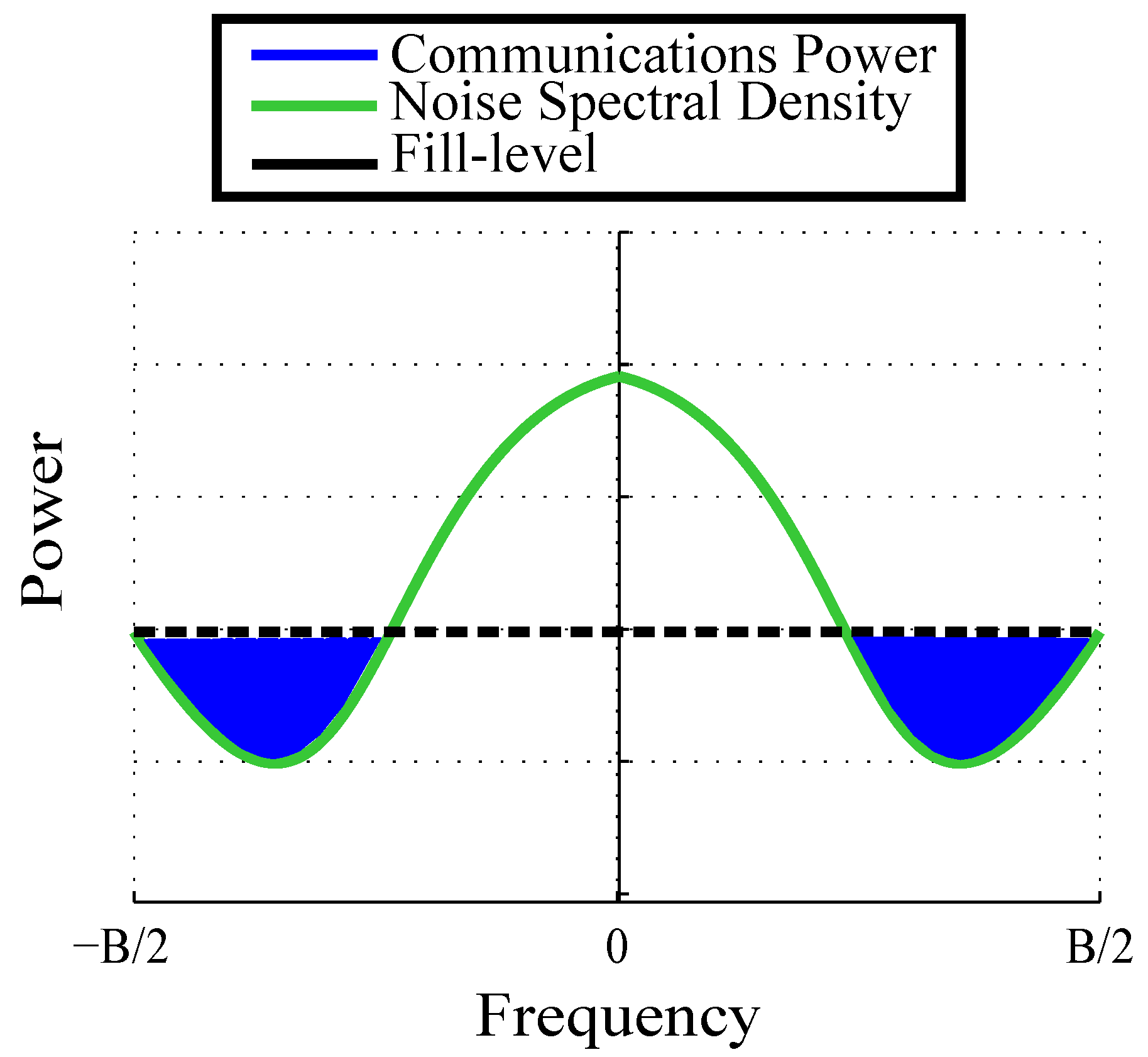
We utilize the continuous spectral WF algorithm [9,61] to determine the optimal communications power distribution over frequency. The continuous spectral WF algorithm optimizes the data rate for a given noise power spectral density [9,61]. This performance metric was first introduced in [62]. Given the noise spectral density at the SIC receiver, N int + n ( f ) , the continuous spectral WF algorithm determines the optimal communications transmit power distribution, P ( f ) , that maximizes the communications data rate at which the joint radar communications receiver decodes the communications message from the radar return suppressed joint received signal. We define this maximized communications rate as the spectral WF SIC data rate which will be used to measure communications performance. The continuous spectral WF algorithm is a continuous form extension of the WF algorithm employed in [3,5]. Figure 3 highlights how the continuous spectral WF algorithm selects the optimal power distribution.
For a SIC receiver, from the communications receiver’s perspective, the noise in the channel is given by Equation (1). In order to find the noise spectral density, N int + n ( f ) , we first calculate the autocorrelation function ( γ ( α ) ) of the band-limited noise signal, n int + n ( t ) (since the received signal is also band-limited) [62],
γ ( α ) = n int + n ( t ) n int + n * ( t α ) = k B T temp B sinc ( π B α ) + a 2 P rad σ τ , proc 2 x ( t τ ) t x * ( t τ α ) t = k B T temp B sinc ( π B α ) + ( 4 π 2 ) a 2 P rad σ τ , proc 2 h ( α ) ,
where sinc ( x ) = sin ( x ) x , and h ( α ) is the inverse Fourier transform with respect to α of H ( f ) = X ( f ) 2 f 2 . Since the noise power spectral density and autocorrelation are Fourier transform pairs, the noise power spectral density is given by [62]
N int + n ( f ) = N ( f ) + N resi ( f ) = k B T temp Π B ( f ) + ( 4 π 2 ) a 2 P rad σ τ , proc 2 X ( f ) 2 f 2 ,
where Π B ( f ) is a top-hat or rectangular function from B 2 to B 2 . The optimal communications power spectrum, P ( f ) , determined by the continuous spectral WF algorithm is given by [9,62]
P ( f ) = μ N int + n ( f ) b 2 + ,
where ( x ) + = x if x 0 ; otherwise ( x ) + = 0 and μ is a constant that is determined from the power constraint
P com = B 2 B 2 d f P ( f ) = B 2 B 2 d f μ N int + n ( f ) b 2 + .
The spectral WF SIC data rate corresponding to the channel with noise spectral density N int + n ( f ) , R com , is given by [9,61]
R com = B 2 B 2 d f log 1 + b 2 P ( f ) N int + n ( f ) .
It should be noted that the integrals shown in Equations (5) and (6) are evaluated numerically to determine the optimal value for μ and the communications data rate, due to the complexity involved in determining analytical solutions for these integrals.

2.3. Global Radar Estimation Rate

We measure radar performance by the estimation rate [3,5,7] which measures the amount of unknown information about the target gained from radar illumination. The estimation rate, R est , is upper bounded as follows:
R est δ 2 T log 2 1 + σ τ , proc 2 σ est 2 ,
where σ est 2 is the range estimation noise variance, which is bounded locally (high SNR regime) by the Cramèr–Rao lower bound [63]. It should be noted that given how the SIC receiver operates, there is no communications interference when performing radar estimation. Hence, the estimation rate given by Equation (7), which measures the estimation performance, has no relationship with the optimal transmit communications signal spectrum, P ( f ) , and the post-SIC noise power spectral density (PSD) N i n t + n ( f ) . A more intuitive understanding of how the estimation rate metric captures target parameter estimation performance can be found in [7]. In this paper, we assume that the radar system is a pulsed system and that the target time-delay or range is the parameter of interest. However, the estimation rate can be extended for different radars and different target parameters, such as continuous signaling radars measuring target velocity or Doppler frequency [64]. As mentioned in Section 1, the estimation rate was extended in [8] to account for global estimation errors or estimation errors occurring in lower SNR regimes. We use the method of interval errors [65] to extend the time-delay estimation performance, σ est 2 , to account for the effect of non-local errors [8]. A closed-form solution of the probability of side-lobe confusion, P s . l . is obtained in terms of the values and locations of the side-lobe peaks, SNR, and the Marcum Q-function Q M [60]. The method of intervals time-delay estimation variance is then given by
σ est 2 = 1 P s . l . ( ISNR ) σ CRLB 2 ( I S N R ) + P s . l . ( I S N R ) ϕ s . l . 2 ,
where ϕ s . l . is the offset in time (seconds) between the autocorrelation peak side-lobe and main-lobe [5]. The probability of side-lobe confusion, P s . l . , is given by [60]
P s . l . ( I S N R ) = 1 Q M I S N R 2 1 + 1 ρ 2 , I S N R 2 1 1 ρ 2 + Q M I S N R 2 1 1 ρ 2 , I S N R 2 1 + 1 ρ 2 ,
where ρ is the ratio of the main-lobe to the peak side-lobe of the autocorrelation function. The Cramèr–Rao lower bound for time delay estimation is given by [66]
σ CRLB 2 = ( 8 π 2 B rms 2 ISNR ) 1 .

3. Joint Waveform Design Problem

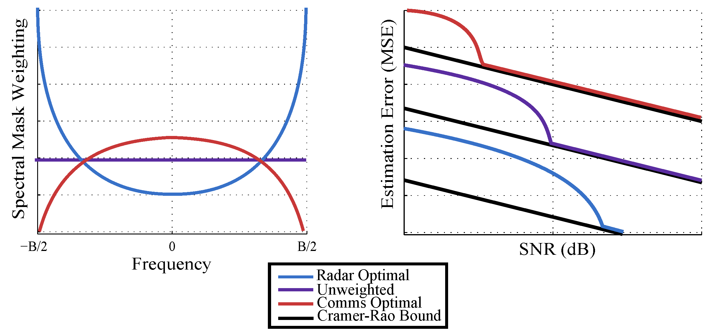
The spectral shape of the waveform (set by the parameters chosen by the design method) determines whether the radar performance or the communications performance is maximized, or some weighting therein. The performance of communications is measured by the communications rate R com (bits/s), given by Equations (6), and the performance of estimation is measured by the global estimation rate, R est , (bits/s), given by Equation (7). Given an amount of spectral allocation or bandwidth, forcing the radar spectrum to be more impulse-like (most of the waveform energy is located at frequencies closer to the center of the bandwidth allocation) will reduce the noise spectral density, N int + n ( f ) , due to minimal radar residual values ( N resi ( f ) ), thereby maximizing the data rate. Conversely, radar waveforms with more energy at frequencies closer to the edges of the bandwidth allocation have larger N resi ( f ) values and consequently, larger N int + n ( f ) values which degrade the communications data rate. The shape of the radar waveform spectrum also impacts radar estimation performance. Radar waveforms with more spectral energy towards the edges have a higher RMS bandwidth which results in better local estimation performance or a smaller Cramèr–Rao lower bound as seen in Equation (9). However, having spectrum with more energy at the edges introduces ambiguity in radar estimation (non-local errors), thereby increasing the SNR threshold at which non-local estimation errors do not occur (local SNR regime), which can negatively impact global estimation performance. Similarly, radar waveforms with more spectral energy towards the center have a smaller RMS bandwidth, resulting in decreased local estimation performance, but a lower threshold for the local SNR regime, potentially resulting in a increased global estimation performance. This relationship between the spectral mask and estimation performance is shown in Figure 4. Thus, the shape of the radar spectrum poses a trade-off not only in terms of radar performance vs. communications performance (through the RMS bandwidth), but also in terms of improved local estimation performance vs. a lower SNR threshold for achieving the Cramèr–Rao bound. The radar waveform spectrum shape is optimized such that the resultant estimation and data rates are jointly maximized.
The objective is to optimize the spectral shape of the radar waveform such that the performance with respect to radar and communications is jointly maximized. We introduce additional constraints to the waveform optimization problem originally defined in [8] in order to obtain radar waveforms that not only ensure optimal joint radar communications performance, but also satisfy additional real-world properties that a traditional radar waveform would satisfy. The new constraints that are introduced are as follows:
  • Peak side-lobe to main-lobe ratio (constraint C 1 ): in [8], the estimation rate was extended to consider global estimation errors (errors occurring when the radar waveform autocorrelation side-lobe is confused for the main-lobe) using the method of interval errors [60]. However, the method of interval errors only considers the errors occurring due to the peak side-lobe and ignores the rest. If the other side-lobes are high enough, they can still have a significant contribution to the global estimation error. By limiting the peak side-lobe to main-lobe ratio to be below a certain threshold, we can reduce the effect the peak side-lobe as well as any other high side-lobes will have on the global estimation error. This constraint is mathematically defined in Equation (11).
  • Spectral leakage (constraint C 2 ): Since the system can only receive signals whose spectrum lies within the system’s bandwidth, any electromagnetic radio frequency (RF) energy that leaks outside of the bandwidth will be lost. To minimize this loss of RF energy, we introduce a constraint on the amount of energy present in the radar spectrum at frequencies out of the system bandwidth range. We enforce this constraint by having the radar spectrum be below a thresholding spectral mask such as the one seen in Figure 5. This constraint is mathematically defined in Equation (11).

4. Method

We present the continuous WF spectral-mask-shaping method which parametrizes the shape of the radar waveform, and then optimizes the parameters to maximize joint radar communications performance. First, as seen in [8], we consider the radar waveform to be a linear frequency modulated chirp signal, which has been passed through a parametrized spectral mask. The spectral mask parameters are then optimized such that the resultant estimation and data rates are jointly maximized. Specifically, we begin with a standard chirp signal (linear frequency modulated) given by x ( t ) = e i ( π B / T ) t 2 . We control the spectral shape of this chirp signal to maximize joint performance. To achieve this, we first sample the chirp signal, and collect N samples in the frequency domain. Let X = ( X ( f 1 ) , , X ( f N ) ) T be the discretized signal in the frequency domain at frequencies f 1 , , f N . Let u = ( u 1 , , u N ) T be an array of spectral weights, where u i [ 0 , 1 ] , i . We control the spectral shape of the chirp signal by multiplying the signal with the spectral weights in the frequency domain such as X u , where ⊙ represents the Hadamard product, such that the resultant radar waveform spectrum is given by X ( f i ) u i i . Furthermore, the RMS bandwidth of the radar waveform can be written (approximately) as a function of u [60]
B rms ( u ) 2 i = 1 N f i 2 X ( f i ) u i 2 i = 1 N X ( f i ) 2 .
Therefore, the dependence of R com on u is apparent from Eqautions (6) and (3), as R com depends on the masked radar waveform spectrum. Similarly, the dependence of R est on u can be understood from Eqautions (7)–(9). Our goal is to choose the spectral weights u such that the resulting waveform jointly maximizes the performance with respect to both radar and communications. Specifically, we maximize a weighted exponential product or weighted geometric mean of the communications rate and the estimation rate. We can also maximize a weighted arithmetic average of the two rates, but the weighted geomteric mean has an edge over the weighted arithmetic mean in the sense that one rate can be extremely small and the other rate can be extremely high if we maximize the weighted arithmetic mean. However, when the weighted geometric mean is maximized, none of the individual rates can be extremely small (or zero). Thus, we choose the geometric mean over the arithmetic mean as our objective function. Additionally, the optimized waveform needs to satisfy the constraints discussed in the previous section: (1) the spectral amplitude at each frequency sample stays below a certain threshold, and (2) the side-lobe to main-lobe ratio of the autocorrelation function is less than a threshold (fraction). The first constraint allows for a limited (and controlled) spectral leakage outside of the system bandwidth. The second constraint decreases the chance of mistaking side-lobes with the main-lobe (non-local estimation errors), which may happen when the side-lobe and main-lobe amplitudes are comparable and when the signal-to-noise ratio fluctuates (due to randomness in the channel). We now pose the joint waveform design problem as a nonlinear program (NLP). As NLPs are typically hard to solve exactly, we present numerical methods to achieve suboptimal solutions. The joint waveform design problem can be stated as follows:
maximize u [ 0 , 1 ] N R com ( u ) α R est ( u ) 1 α , subject to r ( u ) q ( C 1 ) 1 A ( u ) = 1 ( C 2 )
where [ 0 , 1 ] represents the unit interval, 0 α 1 is a weighting parameter, R com ( u ) = i = 1 N d f log 1 + b 2 P ( f i u i ) N int + n ( f i u i ) , and R est ( u ) = δ 2 T log 2 1 + σ τ , proc 2 σ est ( u ) 2 . Here, r ( u ) represents the fraction of the side-lobe to main-lobe amplitude which the constraint C 1 keeps below a threshold value q. Clearly, the side-lobe to main-lobe ratio depends on the waveform’s spectrum, which depends on the spectral mask parameter u . The constraint C 2 constrains the weights u such that the resulting spectrum of the waveform stays below a certain masking threshold. This masking threshold is represented by an indicator function, where A is the set of all spectral weights that let the resulting masked spectrum stay below the masking threshold as shown in Figure 5. Clearly, we have two conflicting objectives—maximizing R com and R est , which makes this a multi-objective optimization problem. For problems like these, there may exist infinitely many Pareto-optimal solutions, i.e., solutions that cannot be improved with respect to any objective without degrading the other objectives. With the following proposition, we prove that the solution to the optimization problem in Eqaution (11) is Pareto-optimal.
Proposition 1.
If u * is the optimal solution to Eqaution (11), then u * is Pareto-optimal.
Proof. 
We prove this by contradiction. Let U be a set of all feasible solutions to the optimization problem in Eqaution (11). Let us assume u * is not Pareto-optimal, which means there exists a feasible solution u ¯ U such that either of the two conditions (enumerated below) is satisfied:
  • R com ( u ¯ ) R com ( u * ) and R est ( u ¯ ) > R est ( u * )
  • R com ( u ¯ ) > R com ( u * ) and R est ( u ¯ ) R est ( u * ) .
If the first condition is true, then for any α [ 0 , 1 ) , the following inequalities hold:
R com ( u ¯ ) R com ( u * ) α 1 & R est ( u ¯ ) R est ( u * ) 1 α > 1
R com ( u ¯ ) α R est ( u ¯ ) 1 α > R com ( u * ) α R est ( u * ) 1 α
which contradicts the assumption that u * is the optimal solution to the NLP in Eqaution (11). When α = 1 , given the first condition is true, the following holds:
R com ( u ¯ ) α R est ( u ¯ ) 1 α R com ( u * ) α R est ( u * ) 1 α ,
which is true if and only if u ¯ = u * . Therefore, if the first condition is true, in either cases α [ 0 , 1 ) and α = 1 , we come to the same conclusion that u * is Pareto-optimal. Using similar arguments, we can show that u * is Pareto-optimal even if the second condition (above) is true. □
In Section 5, we discuss the numerical solutions to the above NLP, and discuss the performance trade-offs. In the following discussion, we derive an expression for the time-domain waveform after a known spectral mask (details discussed below) is applied on the standard chirp signal.

Time Domain Form of Spectrally-Masked Chirp

We now attempt to derive an analytical expression for the spectrally masked chirp signal in the time-domain. As it turns out, deriving a closed-form expression for the masked signal is hard in the case of a discretized mask as discussed in the previous subsection. We attempt to find the expression for a simple scenario, where the mask is continuous and is a quadratic function of the frequency. Given a linear frequency modulated chirp
x ( t ) = e i π B T t 2 ,
with spectrum X ( f ) , we apply the following spectral mask
W ( f ) = c + d f 2 ,
where c and d are real spectral mask parameters that are arbitrarily chosen. The resultant spectrally masked chirp, y ( t ) , has the following spectrum
Y ( f ) = c X ( f ) + d f 2 X ( f ) .
Using the linearity and time derivative properties of the inverse Fourier transform, the spectrally masked chirp in the time domain is given as follows
y ( t ) = c x ( t ) + d 4 π 2 x ( t ) = c e i π B T t 2 + d B 2 t 2 T 2 i d B 2 π T e i π B T t 2 ,
where . represents the second-order derivative with respect to time, t. Although we do not use the above-discussed quadratic mask in our numerical study, nevertheless, the above result may be useful in other studies.

5. Simulation Results and Discussion

In this section, we present an example of the continuous WF spectral-mask shaping waveform design technique discussed in this paper for an example parameter set. The parameters used in the example are shown in Table 2. We also compared the performance of the presented waveform design algorithm with the spectral-mask shaping method derived in [8]. MATLAB’s fmincon [67] was the optimization solver used to solve the optimization problem in Eqaution (11). We used the spectral WF SIC data rate to measure communications performance and the global estimation rate to measure radar performance.

5.1. Spectral-Mask Shaping Method

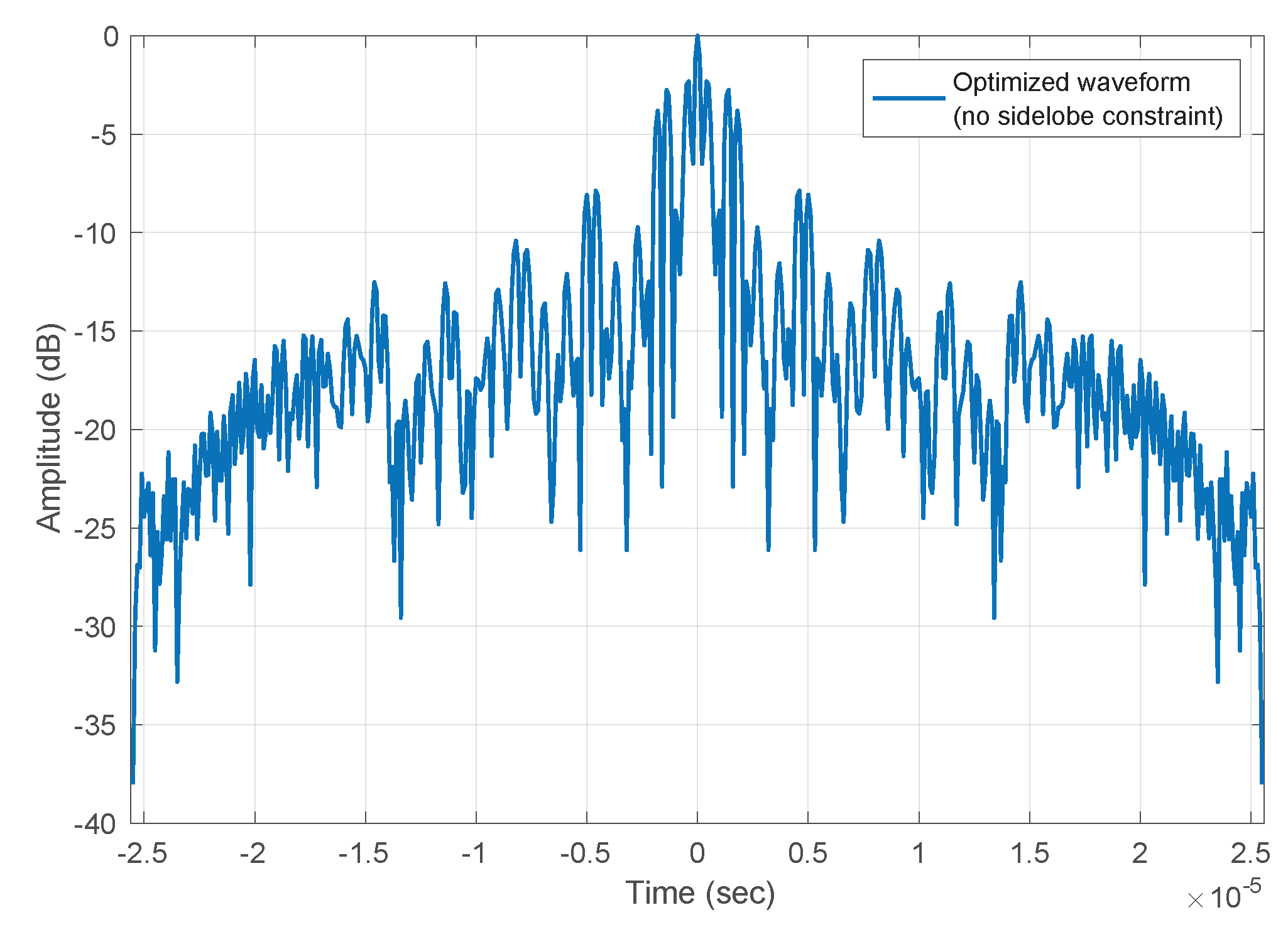
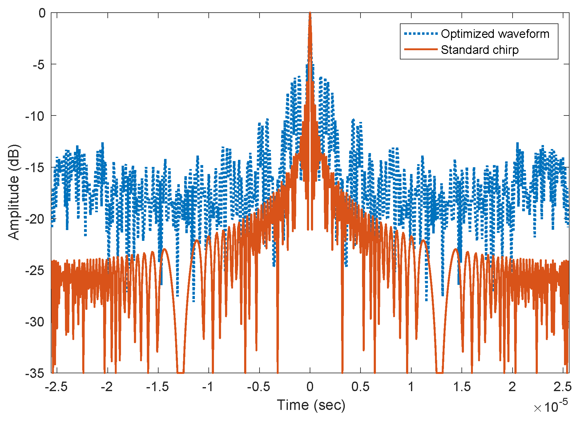
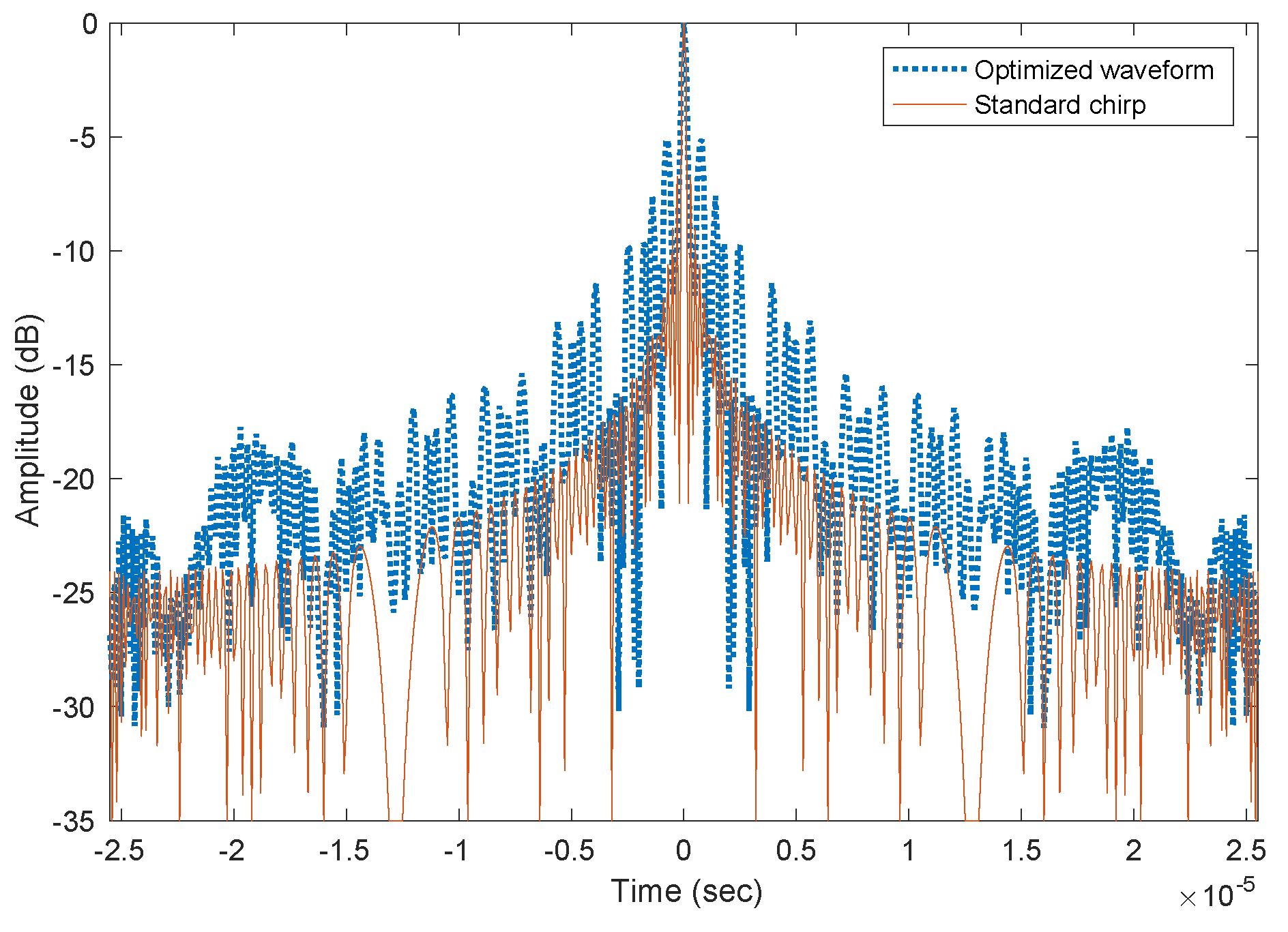
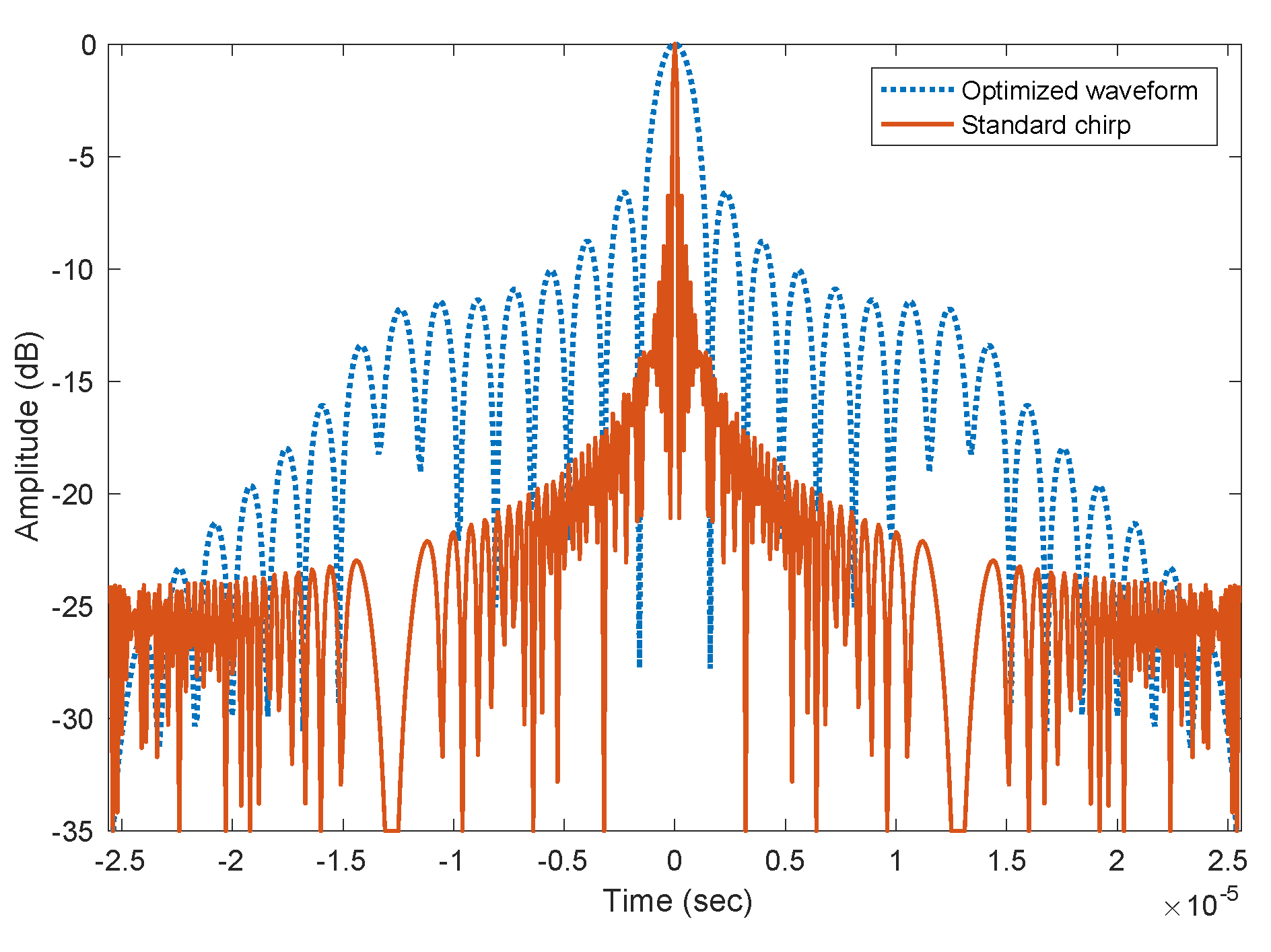
We present a numerical study on the performance of the spectral-mask shaping method discussed in Section 4. All the results presented below were obtained by solving the optimization problem in Eqaution (11) using fmincon for 100 Monte-Carlo runs with randomized initial solutions and selecting the solution with the highest objective value. First, we assessed the impact of the constraints C 1 and C 2 (in Eqaution (11)) on the joint performance. For constraint C 1 , we set the threshold value q = 5 dB. We plotted the autocorrelation function of the optimized radar waveform without imposing constraint C 1 in Figure 6 and in Figure 7, Figure 8 and Figure 9, we plotted the autocorrelation function of the optimized waveform with constraint C 1 imposed for α { 0 , 0.5 , 1 } . When constraint C 1 was not imposed, the peak side-lobe level was 2dB lower than the main-lobe. Enforcing constraint C 1 suppressed the side-lobe by more than 5 dB with respect to the main-lobe as desired. Although we could obtain a better side-lobe to main-lobe ratio by further decreasing the value of q, this came at the cost of reduction in the feasibility region of Eqaution (11) as with any constrained optimization problem, thus decreasing the optimal objective value, i.e., decreasing the joint performance. In these figures, we also noticed that the main-lobe got wider as α increased, which was a result of a decreasing emphasis on R est in Eqaution (11), thus decreasing the σ est 2 value, i.e., increasing range uncertainty by widening the main-lobe.
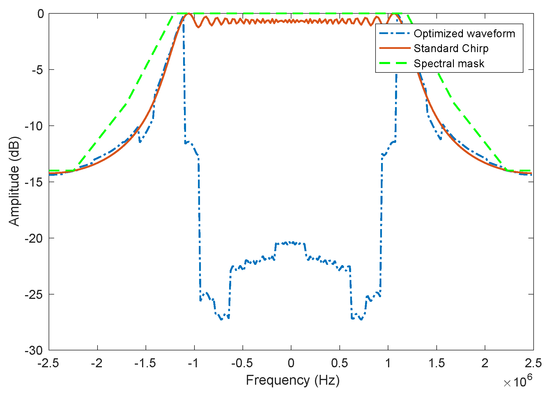
We now study the impact of constraint C 2 on the system performance. Figure 10 and Figure 11 show the spectrum of the optimized waveform with α = 0.5 and with constraint C 2 not imposed and imposed respectively. We chose a masking threshold as depicted in Figure 10 and Figure 11. The design of this masking threshold was inspired from masks that are typically used in 4G-LTE communications. While Figure 10 shows that the amount of spectral leakage that occurred when constraint C 2 was not imposed was less for the selected set of parameters and masking threshold, the amount of spectral leakage could increase when evaluated for a different set of parameters or masking threshold. Since spectral leakage is a major concern for waveform design, imposing constraint C 2 and minimizing the amount of energy that gets leaked outside the frequency band of interest is always desirable. Figure 11 shows that with C 2 , we can suppress the spectral leakage as desired and as determined by the masking threshold we choose, moreover, we achieve this without compromising the quality of the autocorrelation function, as can be seen in Figure 8.
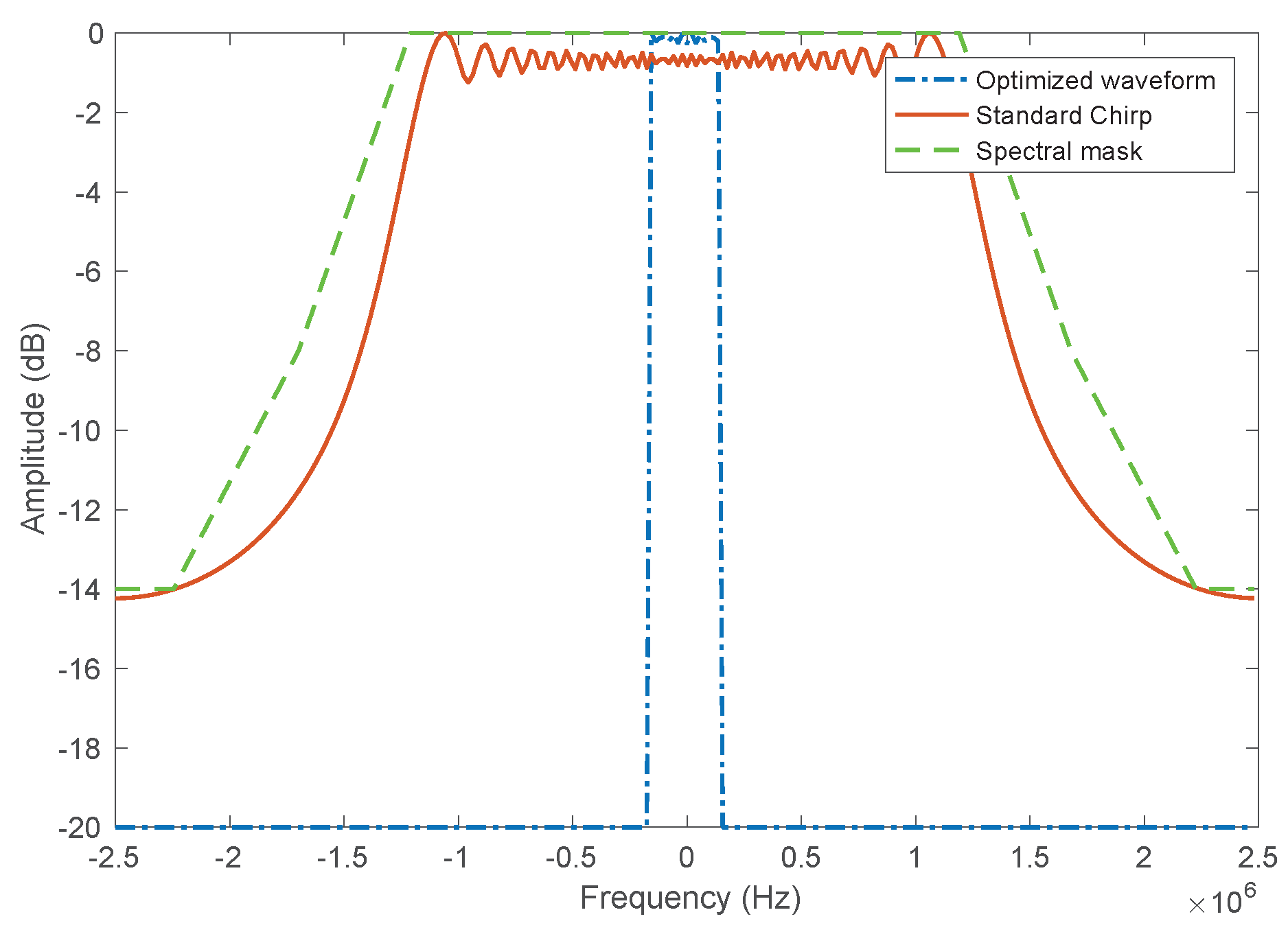
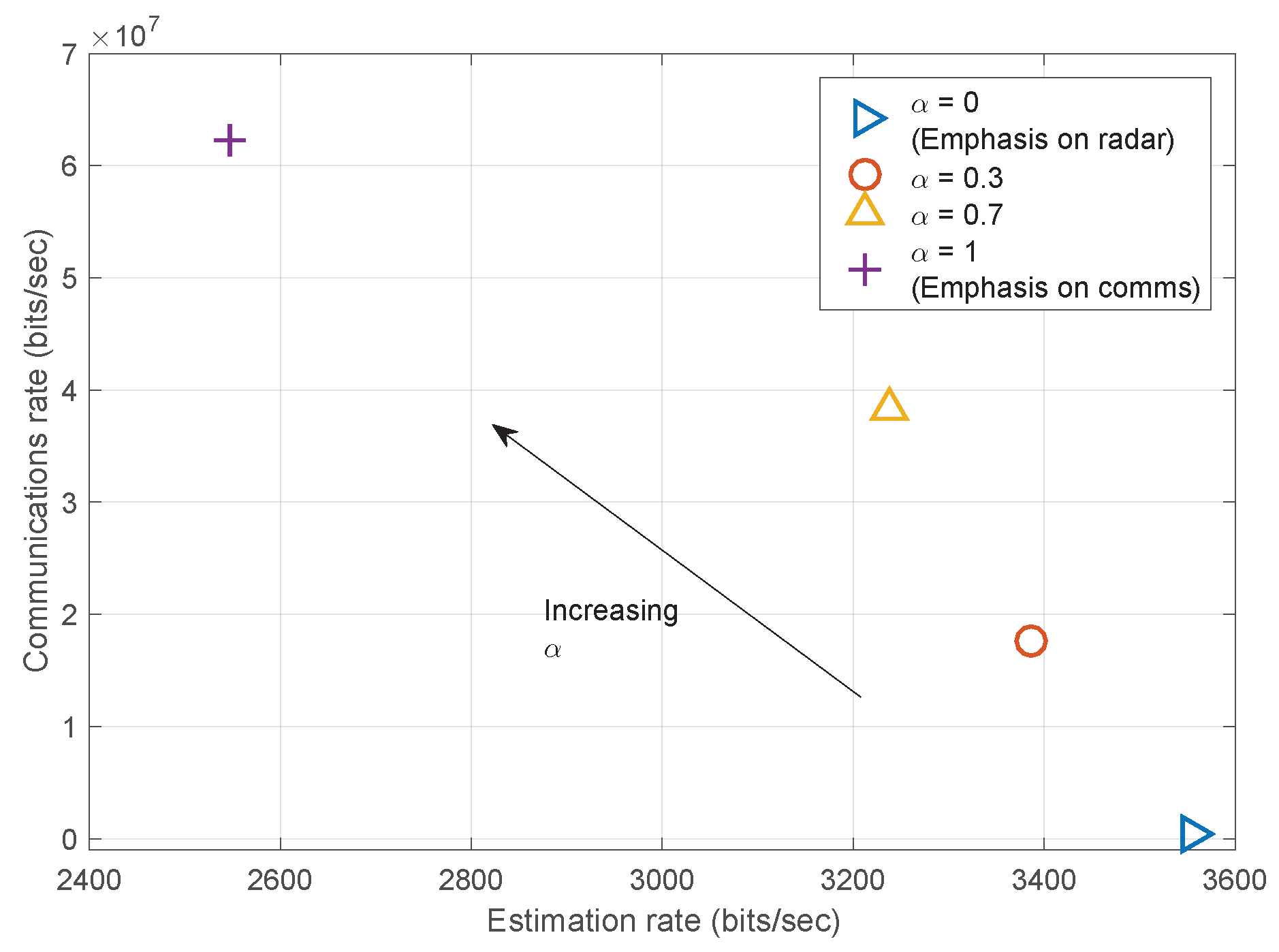
We plotted the spectrum of the optimized waveform with α { 0 , 1 } along with the original unmasked chirp waveform and the thresholding mask used in Figure 12 and Figure 13. In Figure 14, we show a rate-rate curve showing the communications and estimation rate for different values of α . As mentioned earlier in Section 3, radar waveforms with more energy near the edges of the bandwidth allocation minimize the communications rate because they have larger SIC radar residual values, N resi ( f ) . Such waveforms have a higher RMS bandwidth, which results in better local estimation performance, and higher ambiguity in radar estimation, thereby increasing the SNR threshold for the local SNR regime) and possibly degrading global estimation performance. On the other hand, spectrally impulse-like radar waveforms are communications optimal, because such waveforms have minimal N resi ( f ) . Such waveforms also have a smaller RMS bandwidth, resulting in decreased local estimation performance, but a lower threshold for the local SNR regime, potentially causing a improved global estimation performance. Ambiguities affect the global estimation performance or threshold point by causing autocorrelation main-lobe/side-lobe confusion, which is dependent on constraint C 1 , the side-lobeto-main-lobe ratio, as seen in Equation (9). By imposing constraint C 1 , we are also constraining the probability of side-lobe confusion and thereby limiting the effect of ambiguities on global estimation performance. As a result, we expect that as we sweep over α values from 0 to 1 (radar optimal to communications optimal), we expect the waveform spectrum to move from having more energy in the edges of the bandwidth to being more impulse-like. Clearly, from Figure 12, Figure 13 and Figure 14, we observe that this exactly what happened.

5.2. Performance Comparison of Waveform Design Algorithms

We ran a Monte-Carlo study to compare the performance of the continuous WF spectral-mask shaping and the spectral-mask shaping method derived in [8]. We implemented the two methods with the same parameter settings for α = 0.5 . Table 3 shows the average (over the Monte-Carlo runs for α = 0.5 ) of several other performance measures from the Monte-Carlo study such as the final objective values, estimation rates ( R est ), and communications rates ( R com ). From Table 3, we see that the continuous WF spectral-mask shaping method outperformed the spectral-mask shaping method in terms of the final optimal objective value, estimation rate, and communications rate. Furthermore, a significant increase in the achieved communications rate highlights the impact of the continuous WF algorithm.

6. Conclusions

We presented the continuous WF spectral-mask shaping radar waveform design technique which maximizes the performance of a cooperative spectrum sharing radar communications system. The proposed technique is an extension to a previously derived spectral-mask shaping waveform design method, with the new method employing the continuous spectral WF algorithm to improve communications performance. Additional constraints on spectral leakage and radar autocorrelation peak side-lobe to main-lobe ratio are introduced for the waveform design problem and the waveform design method is made more computationally efficient. The global estimation rate, an extension on the estimation rate that takes into account non-local or global estimation errors, and the data rate are used to measure radar and communications performance respectively. The continuous WF spectral-mask shaping method optimizes the spectral mask (to be applied on the standard chirp) such that a weighted mean of the communications rate and the estimation rate is maximized. The weighting decides whether more emphasis is placed on communications performance or radar performance. We presented examples of the waveform design technique discussed in this paper for an example parameter set and also compared the performance of the waveform design method proposed here with the previously derived spectral-mask shaping method. We saw the continuous WF spectral-mask shaping method outperform the spectral-mask shaping method, with a significant increase in the optimal communications rate due to the continuous spectral WF algorithm. The performance of the proposed radar waveform design method will be investigated in more detail in the future against standard communications and radar performance metrics such as bit error rate (BER) and detection probability.

Author Contributions

D.W.B. and A.R.C. developed the metrics and radar waveform design algorithm presented in this paper. S.R. and H.D.M. formulated and solved the optimization problems in the radar waveform design algorithms discussed in this paper. A.R.C. and S.R. provided analysis of the data and results presented in this paper. All authors read, reviewed and approved the final manuscript submitted.

Funding

The work of Alex R. Chiriyath and Daniel W. Bliss was supported in part by the Office of Naval Research. Any opinions, findings, and conclusions or recommendations expressed in this material are those of the authors and do not necessarily reflect the views of the Office of Naval Research or the U.S. Government. The work of Shankarachary Ragi and Hans D. Mittelmann was supported in part by Air Force Office of Scientific Research under grant FA 9550-15-1-0351.

Acknowledgments

The authors would like to thank Bryan Paul and Andrew Herschfelt for their their contributions.

Conflicts of Interest

The authors declare that they have no competing interests.

Abbreviations

The following abbreviations are used in this manuscript:
BERbit error rate
NLPNonlinear Programming
MMSEMinimum Mean-Squared Error
OFDMOrthogonal Frequency-Division Multiplexing
PSDPower Spectral Density
RMSRoot Mean Square
RFElectromagnetic Radio Frequency
SICSuccessive Interference Cancellation
SISOSingle-Input Single-Output
SNRSignal-to-Noise Ratio
WFWater-Filling

References

  1. Paul, B.; Chiriyath, A.R.; Bliss, D.W. Survey of RF Communications and Sensing Convergence Research. IEEE Access 2016, 5, 252–270. [Google Scholar] [CrossRef]
  2. Griffiths, H.; Cohen, L.; Watts, S.; Mokole, E.; Baker, C.; Wicks, M.; Blunt, S. Radar Spectrum Engineering and Management: Technical and Regulatory Issues. Proc. IEEE 2015, 103, 85–102. [Google Scholar] [CrossRef]
  3. Bliss, D.W. Cooperative Radar and Communications Signaling: The Estimation and Information Theory Odd Couple. In Proceedings of the IEEE Radar Conference, Cincinnati, OH, USA, 19–23 May 2014; pp. 50–55. [Google Scholar]
  4. Deng, H.; Himed, B. Interference mitigation processing for spectrum-sharing between radar and wireless communications systems. IEEE Trans. Aerosp. Electron. Syst. 2013, 49, 1911–1919. [Google Scholar] [CrossRef]
  5. Chiriyath, A.R.; Paul, B.; Jacyna, G.M.; Bliss, D.W. Inner Bounds on Performance of Radar and Communications Co-existence. IEEE Trans. Signal Process. 2016, 64, 464–474. [Google Scholar] [CrossRef]
  6. Paul, B.; Bliss, D.W. The Constant Information Radar. Entropy 2016, 18, 338. [Google Scholar] [CrossRef]
  7. Chiriyath, A.R.; Paul, B.; Bliss, D.W. Radar-communications convergence: Coexistence, cooperation, and co-design. IEEE Trans. Cognit. Commun. Netw. 2017, 3, 1–12. [Google Scholar] [CrossRef]
  8. Paul, B.; Chiriyath, A.R.; Bliss, D.W. Joint Communications and Radar Performance Bounds Under Continuous Waveform Optimization: The Waveform Awakens. In Proceedings of the IEEE Radar Conference, Philadelphia, PA, USA, 2–6 May 2016; pp. 865–870. [Google Scholar]
  9. Cover, T.M.; Thomas, J.A. Elements of Information Theory, 2nd ed.; John Wiley & Sons: Hoboken, NJ, USA, 2006. [Google Scholar]
  10. Chiriyath, A.R.; Bliss, D.W. Effect of Clutter on Joint Radar-Communications System Performance Inner Bounds. In Proceedings of the 2015 49th Asilomar Conference on Signals, Systems and Computers, Pacific Grove, CA, USA, 8–11 November 2015; pp. 1379–1383. [Google Scholar]
  11. Chiriyath, A.R.; Bliss, D.W. Joint Radar-Communications Performance Bounds: Data versus Estimation Information Rates. In Proceedings of the 2015 IEEE Military Communications Conference, MILCOM, Tampa, FL, USA, 26–28 October 2015; pp. 1491–1496. [Google Scholar]
  12. Chiriyath, A.R.; Paul, B.; Bliss, D.W. Joint Radar-Communications Information Bounds with Clutter: The Phase Noise Menace. In Proceedings of the IEEE Radar Conference, Philadelphia, PA, USA, 2–6 May 2016; pp. 690–695. [Google Scholar]
  13. Sturm, C.; Wiesbeck, W. Waveform Design and Signal Processing Aspects for Fusion of Wireless Communications and Radar Sensing. Proc. IEEE 2011, 99, 1236–1259. [Google Scholar] [CrossRef]
  14. Turlapaty, A.; Jin, Y.; Xu, Y. Range and Velocity Estimation of Radar Targets by Weighted OFDM Modulation. In Proceedings of the IEEE Radar Conference, Cincinnati, OH, USA, 19–23 May 2014; pp. 1358–1362. [Google Scholar]
  15. Guo, T.; Qiu, R. OFDM Waveform Design Compromising Spectral Nulling, Side-lobe Suppression and Range Resolution. In Proceedings of the IEEE Radar Conference, Cincinnati, OH, USA, 19–23 May 2014; pp. 1424–1429. [Google Scholar]
  16. Lellouch, G.; Mishra, A.; Inggs, M. Impact of the Doppler modulation on the Range and Doppler Processing in OFDM Radar. In Proceedings of the IEEE Radar Conference, Cincinnati, OH, USA, 19–23 May 2014; pp. 803–808. [Google Scholar]
  17. Thompson, S.C.; Stralka, J.P. Constant Envelope OFDM for Power-Efficient Radar and Data Communications. In Proceedings of the International Waveform Diversity and Design Conference, Kissimmee, FL, USA, 8–13 February 2009; pp. 291–295. [Google Scholar]
  18. Krier, J.R.; Norko, M.C.; Reed, J.T.; Baxley, R.J.; Lanterman, A.D.; Ma, X.; Barry, J.R. Performance Bounds for an OFDM-Based Joint Radar and Communications System. In Proceedings of the IEEE Military Communications Conference, Tampa, FL, USA, 26–28 October 2015; pp. 511–516. [Google Scholar]
  19. Hakobyan, G.; Yang, B. A novel OFDM-MIMO radar with non-equidistant subcarrier interleaving and compressed sensing. In Proceedings of the 17th International Radar Symposium (IRS), Krakow, Poland, 10–12 May 2016; pp. 1–5. [Google Scholar]
  20. Sit, Y.L.; Nuss, B.; Basak, S.; Orzol, M.; Zwick, T. Demonstration of interference cancellation in a multiple-user access OFDM MIMO Radar-Communication network using USRPs. In Proceedings of the IEEE MTT-S International Conference on Microwaves for Intelligent Mobility (ICMIM), San Diego, CA, USA, 19–20 May 2016; pp. 1–4. [Google Scholar]
  21. Shi, C.; Wang, F.; Sellathurai, M.; Zhou, J.; Salous, S. Power minimization-based robust OFDM radar waveform design for radar and communication systems in coexistence. IEEE Trans. Signal Process. 2018, 66, 1316–1330. [Google Scholar] [CrossRef] [Green Version]
  22. Shaojian, X.; Bing, C.; Ping, Z. Radar-Communication Integration Based on DSSS Techniques. In Proceedings of the 8th International Conference on Signal Processing, Beijing, China, 16–20 November 2006; Volume 4, pp. 1–4. [Google Scholar]
  23. Xie, Y.; Tao, R.; Wang, T. Method of Waveform design for radar and communication integrated system based on CSS. In Proceedings of the First International Conference on Instrumentation, Measurement, Computer, Communication and Control, Beijing, China, 21–23 October 2011; pp. 737–739. [Google Scholar]
  24. Roberton, M.; Brown, E.R. Integrated radar and communications based on chirped spread-spectrum techniques. In Proceedings of the 2003 IEEE MTT-S International Microwave Symposium Digest, Philadelphia, PA, USA, 8–13 June 2003; Volume 1, pp. 611–614. [Google Scholar]
  25. Nusenu, S.Y.; Wang, W.Q.; Chen, H. Dual-Function MIMO Radar-Communications Employing Frequency-Hopping Chirp Waveforms. Prog. Electromagn. Res. 2018, 64, 135–146. [Google Scholar] [CrossRef] [Green Version]
  26. Aubry, A.; Carotenuto, V.; De Maio, A.; Farina, A.; Pallotta, L. Optimization theory-based radar waveform design for spectrally dense environments. IEEE Aerosp. Electron. Syst. Mag. 2016, 31, 14–25. [Google Scholar] [CrossRef]
  27. Huang, Y.; Piezzo, M.; Carotenuto, V.; De Maio, A. Radar waveform design under similarity, bandwidth priority, and spectral coexistence constraints. In Proceedings of the 2017 IEEE Radar Conference (RadarConf), Seattle, WA, USA, 8–12 May 2017; pp. 1142–1147. [Google Scholar]
  28. Aubry, A.; Carotenuto, V.; De Maio, A. Radar waveform design with multiple spectral compatibility constraints. In Proceedings of the 2016 IEEE Radar Conference (RadarConf), Philadelphia, PA, USA, 2–6 May 2016; pp. 1–6. [Google Scholar]
  29. Qian, J.; Lops, M.; Zheng, L.; Wang, X.; He, Z. Joint System Design for Coexistence of MIMO Radar and MIMO Communication. IEEE Trans. Signal Process. 2018, 66, 3504–3519. [Google Scholar] [CrossRef]
  30. Tang, B.; Naghsh, M.M.; Tang, J. Relative Entropy-Based Waveform Design for MIMO Radar Detection in the Presence of Clutter and Interference. IEEE Trans. Signal Process. 2015, 63, 3783–3796. [Google Scholar] [CrossRef]
  31. Zhu, Z.; Kay, S.; Raghavan, R.S. Information-Theoretic Optimal Radar Waveform Design. IEEE Signal Process. Lett. 2017, 24, 274–278. [Google Scholar] [CrossRef]
  32. Setlur, P.; Devroye, N. Adaptive waveform scheduling in radar: An information theoretic approach. Proc. SPIE 2012, 8361, 836103. [Google Scholar]
  33. Ravenscroft, B.; Owen, J.W.; Jakabosky, J.; Blunt, S.D.; Martone, A.F.; Sherbondy, K.D. Experimental demonstration and analysis of cognitive spectrum sensing and notching for radar. IET Radar Sonar Navig. 2018, 12, 1466–1475. [Google Scholar] [CrossRef] [Green Version]
  34. Nijsure, Y.; Chen, Y.; Yuen, C.; Chew, Y.H. Location-Aware Spectrum and Power Allocation in Joint Cognitive Communication-Radar Networks. In Proceedings of the Sixth International ICST Conference on Cognitive Radio Oriented Wireless Networks and Communications (CROWNCOM), Osaka, Japan, 1–3 June 2011; pp. 171–175. [Google Scholar]
  35. Kirk, B.H.; Narayanan, R.M.; Gallagher, K.A.; Martone, A.F.; Sherbondy, K.D. Avoidance of Time-Varying Radio Frequency Interference With Software-Defined Cognitive Radar. IEEE Trans. Aerosp. Electron. Syst. 2019, 55, 1090–1107. [Google Scholar] [CrossRef]
  36. Palamà, R.; Griffiths, H.; Watson, F. Joint dynamic spectrum access and target-matched illumination for cognitive radar. IET Radar Sonar Navig. 2019, 13, 750–759. [Google Scholar] [CrossRef]
  37. Aubry, A.; De Maio, A.; Piezzo, M.; Naghsh, M.M.; Soltanalian, M.; Stoica, P. Cognitive Radar Waveform Design for Spectral Coexistence in Signal-Dependent Interference. In Proceedings of the IEEE Radar Conference, Cincinnati, OH, USA, 19–23 May 2014; pp. 474–478. [Google Scholar]
  38. Huang, K.W.; Bică, M.; Mitra, U.; Koivunen, V. Radar waveform design in spectrum sharing environment: Coexistence and cognition. In Proceedings of the 2015 IEEE Radar Conference, Arlington, VA, USA, 10–15 May 2015; pp. 1698–1703. [Google Scholar]
  39. Nijsure, Y.; Chen, Y.; Boussakta, S.; Yuen, C.; Chew, Y.H.; Ding, Z. Novel System Architecture and Waveform Design for Cognitive Radar Radio Networks. IEEE Trans. Veh. Technol. 2012, 61, 3630–3642. [Google Scholar] [CrossRef]
  40. Baylis, C.; Egbert, A.; Alcala-Medel, J.; Dockendorf, A.; Calabrese, C.; Langley, E.; Martone, A.; Gallagher, K.; Viveiros, E.; Peroulis, D.; et al. Reconfigurable and Adaptive Radar Amplifiers for Spectrum Sharing in Cognitive Radar. In Proceedings of the 2019 IEEE Radar Conference (RadarConf), Boston, MA, USA, 22–26 April 2019; pp. 1–3. [Google Scholar]
  41. Shannon, C. A Mathematical Theory of Communication. Bell Syst. Tech. J. 1948, 27, 379–423, 623–656. [Google Scholar] [CrossRef] [Green Version]
  42. Woodward, P. Information Theory and the Design of Radar Receivers. Proc. IRE 1951, 39, 1521–1524. [Google Scholar] [CrossRef]
  43. Bell, M.R. Information Theory and Radar Waveform Design. IEEE Trans. Inf. Theory 1993, 39, 1578–1597. [Google Scholar] [CrossRef] [Green Version]
  44. Guo, D.; Shamai, S.; Verdú, S. The Interplay Between Information and Estimation Measures; Foundations and Trends in Signal Processing; Now Publishers Inc.: Hanover, MA, USA, 2012; Volume 6, pp. 243–429. [Google Scholar]
  45. Tian, T.; Zhang, T.; Kong, L.; Cui, G.; Wang, Y. Mutual Information based Partial Band Coexistence for Joint Radar and Communication System. In Proceedings of the 2019 IEEE Radar Conference (RadarConf), Boston, MA, USA, 22–26 April 2019; pp. 1–5. [Google Scholar]
  46. Khawar, A.; Abdel-Hadi, A.; Clancy, T.C. Spectrum sharing between S-band radar and LTE cellular system: A spatial approach. In Proceedings of the IEEE International Symposium on Dynamic Spectrum Access Networks (DYSPAN), McLean, VA, USA, 1–4 April 2014; pp. 7–14. [Google Scholar]
  47. Sodagari, S.; Khawar, A.; Clancy, T.C.; McGwier, R. A Projection Based Approach for Radar and Telecommunication Systems Coexistence. In Proceedings of the IEEE Global Communications Conference (GLOBECOM), Anaheim, CA, USA, 3–7 December 2012; pp. 5010–5014. [Google Scholar]
  48. Shajaiah, H.; Abdelhadi, A.; Clancy, C. Spectrum Sharing Approach between Radar and Communication Systems and its Impact on Radar’s Detectable Target Parameters. In Proceedings of the IEEE 81st Vehicular Technology Conference (VTC Spring), Glasgow, UK, 11–14 May 2015; pp. 1–6. [Google Scholar]
  49. Liu, F.; Masouros, C.; Li, A.; Sun, H.; Hanzo, L. MU-MIMO communications with MIMO radar: From co-existence to joint transmission. IEEE Trans. Wirel. Commun. 2018, 17, 2755–2770. [Google Scholar] [CrossRef]
  50. Zhang, W.; Vedantam, S.; Mitra, U. Joint Transmission and State Estimation: A Constrained Channel Coding Approach. IEEE Trans. Inf. Theory 2011, 57, 7084–7095. [Google Scholar] [CrossRef] [Green Version]
  51. Stinco, P.; Greco, M.; Gini, F.; Himed, B. Channel parameters estimation for cognitive radar systems. In Proceedings of the 2014 4th International Workshop on Cognitive Information Processing (CIP), Copenhagen, Denmark, 26–28 May 2014; pp. 1–6. [Google Scholar]
  52. Pezeshki, A.; Calderbank, A.R.; Moran, W.; Howard, S.D. Doppler Resilient Golay Complementary Waveforms. IEEE Trans. Inf. Theory 2008, 54, 4254–4266. [Google Scholar] [CrossRef] [Green Version]
  53. Li, B.; Petropulu, A. MIMO radar and communication spectrum sharing with clutter mitigation. In Proceedings of the 2016 IEEE Radar Conference (RadarConf), Philadelphia, PA, USA, 2–6 May 2016; pp. 1–6. [Google Scholar]
  54. Hassanien, A.; Amin, M.G.; Zhang, Y.D.; Ahmad, F. A dual function radar-communications system using sidelobe control and waveform diversity. In Proceedings of the 2015 IEEE Radar Conference, Arlington, VA, USA, 10–15 May 2015; pp. 1260–1263. [Google Scholar]
  55. Ahmed, A.; Zhang, Y.D.; Himed, B. Distributed Dual-Function Radar-Communication MIMO System with Optimized Resource Allocation. In Proceedings of the 2019 IEEE Radar Conference (RadarConf), Boston, MA, USA, 22–26 April 2019; pp. 1–5. [Google Scholar]
  56. Hassanien, A.; Amin, M.G.; Zhang, Y.D.; Ahmad, F.; Himed, B. Non-coherent PSK-based dual-function radar-communication systems. In Proceedings of the IEEE Radar Conference, Philadelphia, PA, USA, 2–6 May 2016; pp. 1–6. [Google Scholar]
  57. Dokhanchi, S.H.; Shankar, M.B.; Nijsure, Y.A.; Stifter, T.; Sedighi, S.; Ottersten, B. Joint automotive radar-communications waveform design. In Proceedings of the 2017 IEEE 28th Annual International Symposium on Personal, Indoor, and Mobile Radio Communications (PIMRC), Montreal, QC, Canada, 8–13 October 2017; pp. 1–7. [Google Scholar]
  58. Dokhanchi, S.H.; Mysore, B.S.; Mishra, K.V.; Ottersten, B. A mmWave Automotive Joint Radar-Communications System. IEEE Trans. Aerosp. Electron. Syst. 2019, 55, 1241–1260. [Google Scholar] [CrossRef]
  59. Dokhanchi, S.H.; Bhavani Shankar, M.R.; Mishra, K.V.; Stifter, T.; Ottersten, B. Performance Analysis of mmWave Bi-static PMCW-based Automotive Joint Radar-Communications System. In Proceedings of the 2019 IEEE Radar Conference (RadarConf), Boston, MA, USA, 22–26 April 2019; pp. 1–6. [Google Scholar]
  60. Bliss, D.W.; Govindasamy, S. Adaptive Wireless Communications: MIMO Channels and Networks; Cambridge University Press: New York, NY, USA, 2013. [Google Scholar]
  61. Gallager, R.G. Information Theory and Reliable Communication, 2nd ed.; John Wiley & Sons: Hoboken, NJ, USA, 1968. [Google Scholar]
  62. Chiriyath, A.R.; Ragi, S.; Mittelmann, H.D.; Bliss, D.W. Novel Radar Waveform Optimization for a Cooperative Radar-Communications System. IEEE Trans. Aerosp. Electron. Syst. 2019, 55, 1160–1173. [Google Scholar] [CrossRef]
  63. Kay, S.M. Fundamentals of Statistical Signal Processing: Estimation Theory, 1st ed.; Prentice-Hall, Inc.: Upper Saddle River, NJ, USA, 1993. [Google Scholar]
  64. Paul, B.; Bliss, D.W. Extending Joint Radar-Communications Bounds for FMCW Radar with Doppler Estimation. In Proceedings of the IEEE Radar Conference, Arlington, VA, USA, 10–15 May 2015; pp. 89–94. [Google Scholar]
  65. Van Trees, H. Detection, Estimation, and Modulation Theory: Part 1, 1st ed.; John Wiley & Sons: Hoboken, NJ, USA, 2004. [Google Scholar]
  66. Richards, M.A. Principles of Modern Radar: Basic Principles; SciTech Publishing: Raleigh, NC, USA, 2010. [Google Scholar]
  67. Mathworks. MATLAB’s fmincon. Available online: https://www.mathworks.com/help/optim/ug/fmincon.html?requestedDomain=www.mathworks.com (accessed on 15 November 2019).
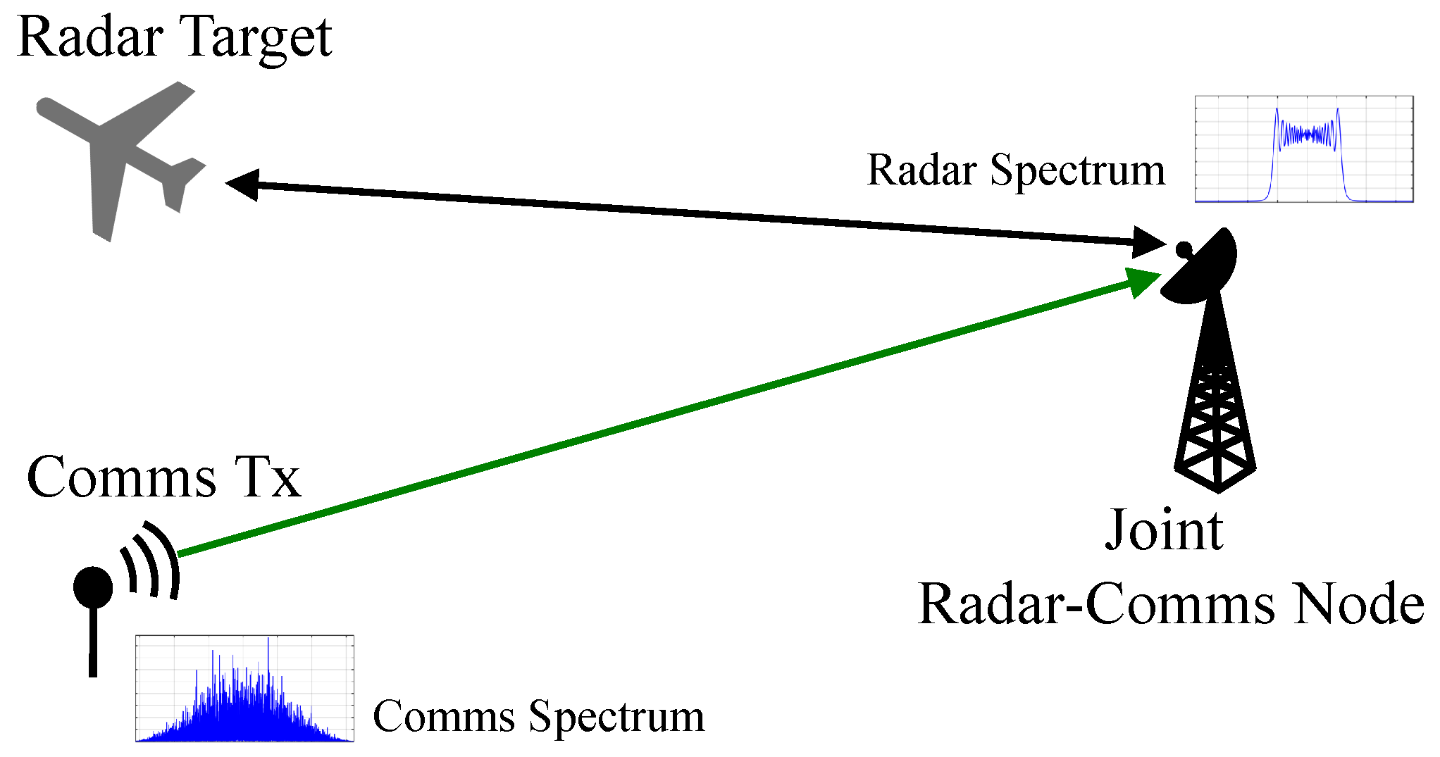
Figure 1. The joint radar communications system simulation scenario for radar waveform design. In this scenario, a radar and communications user attempt to use the same spectrum space–time. The joint radar communications receiver optimizes the shape of the radar waveform spectrum to maximize joint radar communications performance. This scenario is instructional, and can easily be scaled to more complicated scenarios by using it as a building block to construct real world examples.
Electronics 08 01498 g001
Figure 2. The joint radar communications system block diagram for the SIC scenario. The radar and communications signals have two effective channels, but arrive converged at the joint receiver. The radar signal is predicted and removed, allowing a reduced rate communications user to operate. Assuming near perfect decoding of the communications user, the ideal signal can be reconstructed and subtracted from the original waveform, allowing for unimpeded radar access.
Electronics 08 01498 g002
Figure 3. A notional example of the continuous spectral WF algorithm. The black, dashed line indicates the fill level (maximum amount of communications power that can be allocated at any frequency), the green curve represents the noise power spectral density N int + n ( f ) , and the optimal communications power spectral distribution is shown in blue.
Electronics 08 01498 g003
Figure 4. The relationship between the spectral mask and radar estimation performance. The purple line shows the estimation performance when there is no spectral mask. The estimation performance when a communications optimal spectral mask (waveforms with more spectral energy towards the center) is used is shown in red. Estimation performance when a radar optimal spectral mask (waveforms with more spectral energy towards the edges) is used is shown in blue. The Cramèr–Rao bound is shown in black.
Electronics 08 01498 g004
Figure 5. Spectral leakage mask used constrain the amount of energy in the radar spectrum leaking out at frequencies out of the system bandwidth range. The spectral leakage constraint is enforced by having the radar spectrum be below this thresholding spectral leakage mask.
Electronics 08 01498 g005
Figure 6. Radar waveform autocorrelation function of the optimized waveform with α = 0.5 and no constraint C 1 . We see that without enforcing the constraint C 1 results in high side-lobe levels, about 2dB lower than the main-lobe.
Electronics 08 01498 g006
Figure 7. Radar waveform autocorrelation function of the optimized waveform with α = 0 . We see that enforcing the constraint C 1 suppresses the side-lobe by more than 5 dB with respect to the main-lobe as desired.
Electronics 08 01498 g007
Figure 8. Radar waveform autocorrelation function of the optimized waveform with α = 0.5 . We see that enforcing the constraint C 1 suppresses the side-lobe by more than 5 dB with respect to the main-lobe as desired.
Electronics 08 01498 g008
Figure 9. Radar waveform autocorrelation function of the optimized waveform with α = 1 . We see that enforcing the constraint C 1 suppresses the side-lobe by more than 5 dB with respect to the main-lobe as desired.
Electronics 08 01498 g009
Figure 10. Radar waveform spectrum with α = 0.5 and without constraint C 2 imposed. The masking threshold used is depicted by the green dashed line, and the optimal masked chirp waveform spectrum is shown by the blue dotted line. While Figure 10 shows that the amount of spectral leakage that occurs when constraint C 2 was not imposed was less for the selected set of parameters and masking threshold, the amount of spectral leakage could increase when evaluated for a different set of parameters or masking threshold. Since spectral leakage is a major concern for waveform design, imposing constraint C 2 and minimizing the amount of energy that gets leaked outside the frequency band of interest is always desirable.
Electronics 08 01498 g010
Figure 11. Radar waveform spectrum with α = 0.5 and constraint C 2 imposed. The masking threshold used in depicted by the green dashed line, the unmasked chirp waveform spectrum is shown by the red line, and the optimal masked chirp waveform spectrum is shown by the blue dotted line. We see that with constraint C 2 imposed, we were able to suppress the spectral leakage as desired and as determined by the spectral mask we chose.
Electronics 08 01498 g011
Figure 12. Radar waveform spectrum with α = 0 along with the original unmasked chirp waveform and the thresholding mask. The optimized waveform is depicted by the blue dotted line, the original unmasked chirp is depicted by the red line, and the masking threshold is depicted by the green dashed line. This waveform spectrum is radar-optimal and has more energy in the edges of the bandwidth.
Electronics 08 01498 g012
Figure 13. Radar waveform spectrum with α = 1 along with the original unmasked chirp waveform and the thresholding mask. The optimized waveform is depicted by the blue dotted line, the original unmasked chirp is depicted by the red line, and the masking threshold is depicted by the green dashed line. This waveform spectrum is communications-optimal and has more energy at the center of the bandwidth.
Electronics 08 01498 g013
Figure 14. Rate–rate curve depicting communications and estimation rates vs. α . Communications and estimation rate pairs are shown for α { 0 , 0.3 , 0.7 , 1 } .
Electronics 08 01498 g014
Table 1. Survey of notation.
VariableDescription
· Expectation
· L2-norm or absolute value
Q M ( . ) Marcum Q-function
δ ( . ) Dirac-delta function
fFrequency
tTime
BFull bandwidth of the system
B rms Root-mean-squared radar bandwidth
x ( t ) Unit-variance transmitted radar signal
X ( f ) Radar signal frequency response
P rad Radar power
τ Time delay to target
aTarget complex combined antenna, cross-section, and propagation gain
TRadar pulse duration
δ Radar duty factor
P com Total communications power
P ( f ) Optimal communications transmit distribution
bComplex combined antenna gain and communications propagation loss
n ( t ) Receiver thermal noise
n resi ( t ) Post-SIC radar residual
σ noise 2 Thermal noise power
k B Boltzmann constant
T temp Absolute temperature
σ τ , proc 2 Variance of range fluctuation process
σ CRLB 2 Cramèr-Rao lower bound or estimation error variance
I S N R Integrated radar SNR
Table 2. Parameters for Waveform Design Methods.
ParameterValue
Bandwidth (B)5 MHz
Center frequency3 GHz
Effective temperature ( T temp )1000 K
Communications range10 km
Communications power ( P com )1 W
Communications antenna Gain20 dBi
Communications receiver Side-lobe Gain10 dBi
Radar target range11.2 km
Radar antenna gain30 dBi
Radar power ( P rad ) 1 kW
Target cross section10 m2
Target process standard deviation ( σ τ , proc )100 m
Time–bandwidth product ( T B )128
Radar duty factor ( δ )0.01
Table 3. WF continuous wave (CW) spectral-mask shaping vs. spectral-mask shaping for α = 0 . 5 .
Performance Metric (Average Values)CW Spectral-Mask ShapingSpectral-Mask Shaping
Final objective value 3.35 × 10 5 6.48 × 10 3
R est (b/s) 3.47 × 10 3 3.05 × 10 3
R com (b/s) 3.24 × 10 7 1.38 × 10 4