Article

High-Performance Compact Multi-Mode UWB Filter using High-Temperature Superconductivity

1
The School of Aeronautics and Astronautics, University of Electronic Science and Technology of China, Chengdu 611731, China
2
Department of Mechanical Engineering, City University of Hong Kong, 83 Tat Chee Avenue, Kowloon Tong, Kowloon, Hong Kong, China
*
Author to whom correspondence should be addressed.
Electronics 2019, 8(12), 1473; https://doi.org/10.3390/electronics8121473
Submission received: 4 November 2019 / Revised: 27 November 2019 / Accepted: 30 November 2019 / Published: 4 December 2019
(This article belongs to the Special Issue RF/Microwave Antenna, Circuit, and System Design for UAV Applications)

Abstract

:
A high-performance miniaturized multi-mode ultra-wide band (UWB) filter is proposed in this paper. The simple compact quintuple-mode resonator is constructed by loading three sets of open stubs on a modified conventional triple-mode resonator. Even and odd mode analytical methods are applied to analyze it. In addition, the function of each part of the filter is studied in cases of weak/strong coupling. In order to further improve the insertion loss, selectivity and out-of-band suppression, the designed filter is finally fabricated on double-sided YBCO/MgO/YBCO high-temperature superconducting (HTS) film. The test results show that the HTS UWB filter has excellent performance, and the simulation results are in good agreement with the test ones. The 3-dB bandwidth covers 3.6 ~ 13.2 GHz. The maximum insertion loss in the band was only 0.32 dB, and the reflection was better than –15.1 dB. The band-edge roll-off rate was 56 dB/GHz and the upper stopband with 20 dB rejection extended to 20.7 GHz.

1. Introduction

Because of the rapid development of fifth generation (5G) communication and Internet of Things (IoT) technology, ultra-wide band (UWB) wireless communication system has become a hot research topic. UWB filtering is one of the most important passive components in the system, and its performance seriously affects the quality of received and transmitted signals. An excellent UWB filter should have the characteristics of low insertion loss, a low-voltage standing wave ratio (VSWR), a high band-edge roll-off rate and small size. Constructing a multi-mode resonator is one of the useful methods for designing a UWB filter, and was first proposed by Lei Zhu et al. in 2005 [1]. At present, many kinds of UWB filters based on multi-mode resonators have been widely studied by researchers [2,3,4,5,6,7,8,9]. Stub-loading configurations [2,6,8,10,11] and ring resonators [12,13] are two effective approaches to realizing the multi-mode resonator. In 2018, we designed two UWB filters based on these two structures [14,15], but their return loss and dimension still have room for improvement. In [7,9,10,16], relatively high insertion loss was shown to be a disadvantage of these filters. There are also some UWB filters in which the performance is good, but their structures are comparatively complex, so the simulation difficulty and efficiency increase [2,17].
In this study, the high-impedance lines of the traditional triple-mode resonator were bent by 90 degrees, and on the basis of this we loaded three sets of different open stubs on the low-impedance section to ultimately form a simple compact quintuple-mode resonator. In addition to introducing two modes, several transmission zeros (TZs) were also generated, effectively improving the band-edge selectivity. Furthermore, with the stepped-impedance parallel coupling line feeding the filter, two new transmission poles (TPs) were introduced, and the upper stopband suppression level was improved as well. Finally, the UWB filter was fabricated on a high-temperature superconductor to efficaciously ameliorate the problems mentioned above.

2. Analysis and Design of the UWB Filter

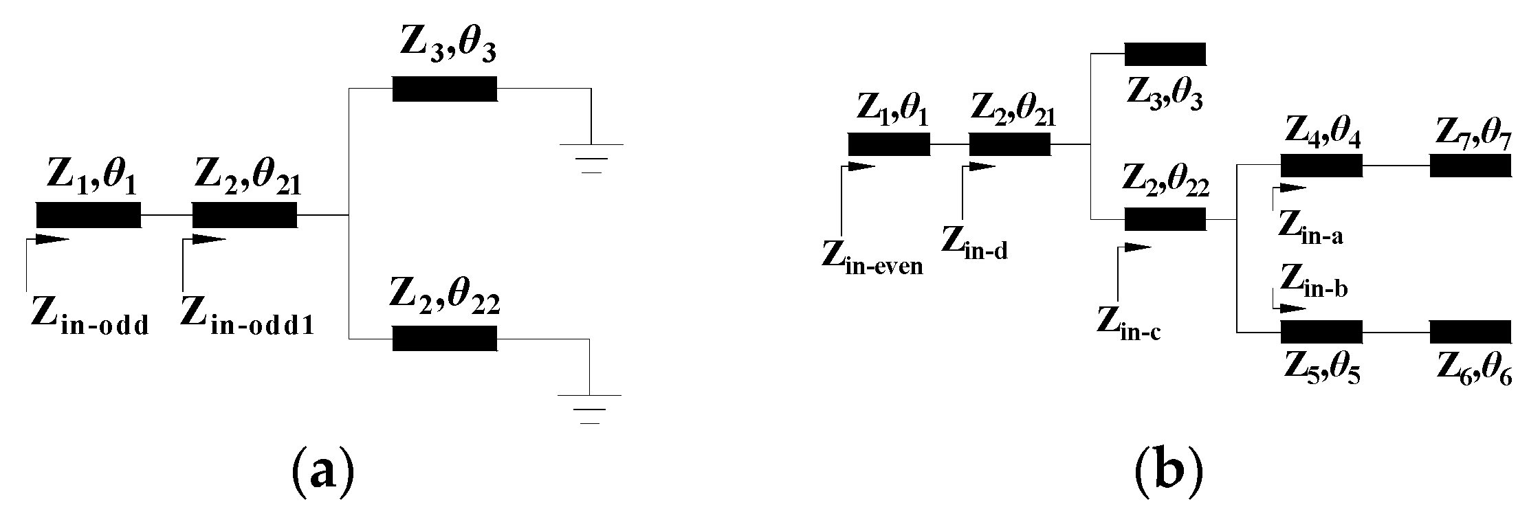
Since the proposed resonator structure is symmetrical with the horizontal X-axis, we use odd and even analytical methods to analyze it theoretically. Even and odd mode analysis is highly effective for analyzing multi-mode resonators. Through the theoretical calculation of the input impedance of the equivalent circuits in the odd and even modes, we can clearly deduce the influence of the resonator parameters on the modes within the passband. Figure 1 shows the construction process of the proposed simple compact quintuple-mode resonator. It can be seen that it is made up of a folded triple-mode resonator and three sets of open stubs. Figure 2a,b shows the equivalent transmission line circuits of the odd and even modes.
According to transmission line theory, by ignoring all the parasitic effects and radiation from the transmission line segments, the odd-mode input impedance (Zin-odd) for Figure 2a can be calculated through Equations (1) and (2). The resonance condition for odd-mode frequencies can be obtained by equating 1/Zin-odd = 0, which gives Equation (3).
Z i n o d d 1 = Z 2 Z 2 Z 3 tan θ 22 tan θ 3 Z 2 tan θ 21 ( Z 3 tan θ 3 + Z 2 tan θ 22 ) j Z 2 ( Z 3 tan θ 3 + Z 2 tan θ 22 ) j Z 2 Z 3 tan θ 21 tan θ 22 tan θ 3
Z i n o d d = Z 1 Z i n o d d 1 + j Z 1 tan θ 1 Z 1 + j Z i n o d d 1 tan θ 1
Z 1 + j Z i n o d d 1 tan θ 1 = 0
The even-mode input impedance (Zin-even) for Figure 2b can be derived from Equations (4)–(8).
Z in - a = j Z 4 Z 7 + j Z 4 2 tan θ 4 tan θ 7 Z 4 tan θ 7 + Z 7 tan θ 4
Z in - b = j Z 5 Z 6 + j Z 5 2 tan θ 5 tan θ 6 Z 5 tan θ 6 + Z 6 tan θ 5
Z in - c = Z 2 Z in - a Z in - b + j Z 2 2 ( Z in - a + Z in - b ) tan θ 22 Z 2 ( Z in - a + Z in - b ) + j Z in - a Z in - b tan θ 22
Z in - d = j Z 2 Z 3 Z in - c + j Z 2 2 ( Z in - c tan θ 3 j Z 3 ) tan θ 21 Z 2 ( Z in - c tan θ 3 j Z 3 ) + Z 3 Z in - c tan θ 21
Z in - even = Z 1 Z in - d + j Z 1 tan θ 1 Z 1 + Z in - d tan θ 1
The resonance condition for even-mode frequencies can be obtained equating 1/Zin-even = 0, which gives Equation (9).
Z 1 + Z in - d tan θ 1 = 0
From the equations above, we can deduce that all the controllable odd- and even-mode frequencies are of great significance for the fulfilment of the UWB bandwidth, as they can be flexibly tuned in the passband by choosing proper electrical lengths and characteristic impedances of the transmission line sections, especially the three loaded open stubs.
Generally, the design of multi-order filters requires a coupling scheme and associated coupling matrix. The UWB filter we designed is a single-order multi-mode resonator, so there is no coupling matrix. Only the input and output of the resonator need a strong coupling feed to meet the requirements of UWB. The above derived equations are mainly used to find out the parameters that affect the even and odd modes (the resonant frequencies in the passband) of the proposed resonator. These equations cannot accurately determine the positions of the in-band resonances, and can only provide direction for the adjustment of the filter dimension parameters. By reviewing a large number of references on single-order multi-mode UWB filters, it can also be seen that the original-size parameters in this type of filter are often difficult to calculate with a mathematical formula, and only some key dimensions of the structure can be determined at the beginning. For example, the size of the modified triple-mode SIR used in this paper can be determined according to [1]; that is, the lengths of the identical high-impedance lines at the two sides are selected to be about λ/4 (λ: guided-wavelength) or 3.7 mm at the central frequency 8.4 GHz, and the width is set to 0.05 mm to achieve strong coupling. The length of the low-impedance line in the middle part is about λ/2 (6.3 mm), and the width is determined as 0.6 mm based on the roughly uniform distribution of the three modes. The initial size of the three sets of open stubs can be easily obtained through trial and error under the requirements of mode distribution, passband coverage and TZ locations. The original low-impedance lines’ lengths and widths of Stub1 and Stub2 are chosen to be 0.9, 0.5, 3.3 and 2.9 mm, respectively; the lengths of their high-impedance lines are 0.5, 1.3 and 0.08 mm, respectively, with 0.9 and 0.2 mm selected as the starting length and width values of Stub3, respectively. The input/output 50 Ω line width can be calculated as 0.49 mm according to the substrate parameters and the centre frequency of the UWB filter. In order to achieve the required UWB performance, the width of the parallel-coupling line is fixed at 0.035 mm at the beginning. So far, all the initial size parameters of the proposed UWB filter are approximately attained.
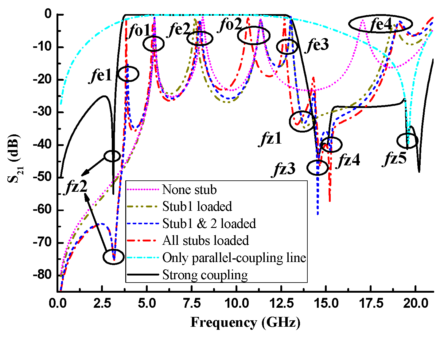
Figure 3 depicts the function of each part of the proposed quintuple-mode resonator. The results of adding open stubs are observed under the condition of weak coupling. In the middle position on the right side of the bent triple-mode resonator, we can also see that the stepped-impedance open Stub1 loaded horizontally can introduce an even-mode resonance fe3 and a TZ fz1 at high frequency, as well as pushing the higher-order even-mode fe4 generated by the triple-mode resonator to a higher frequency to improve the upper stopband performance. Due to the high-impedance-ratio Stub2, another new even-mode fe1 and TZ fz2 are produced at a low frequency, and two more TZs (fz3 and fz4) are created next to fz1. It is noteworthy that the S21 curve on the right side of fz1 is pulled down because of the TZs fz3 and fz4 close to fz1, which leads to the formation of a peak. From the previous analysis of even and odd modes, we know that Stub1 and Stub2 only affect the frequencies of even modes, and have no effect on the frequencies of odd modes. Therefore, whether the five modes in the passband are even or odd mode can be obviously identified, and this annotation is marked in the figure. Although all even and odd modes will be affected when Stub3 is loaded, the odd-mode fo2 and even-mode fe3 will shift dramatically compared to the others. These two modes move to low frequencies with different degrees, which makes the distribution of the five modes in the passband more reasonable. The S21 response of the proposed quintuple-mode resonator under strong coupling condition is also plotted in Figure 3 by the black solid line. In fact, the passband is eventually formed by three even modes, two odd modes and two TPs derived from the stepped-impedance parallel coupling line (to be explained in detail later) under strong coupling. Because of the strong coupling effect of parallel coupling line, the action of the TZ fz1 is offset (with the increase of the parallel coupling line length L3, the rejection level of fz1 is gradually weakened.). The remaining TZs fz2, fz3 and fz4 substantially enhance the selectivity on both sides of the passband. In addition, with the use of the parallel coupling line, the TZ fz5 is generated to notably ameliorate the suppression extent and width of the upper stopband.
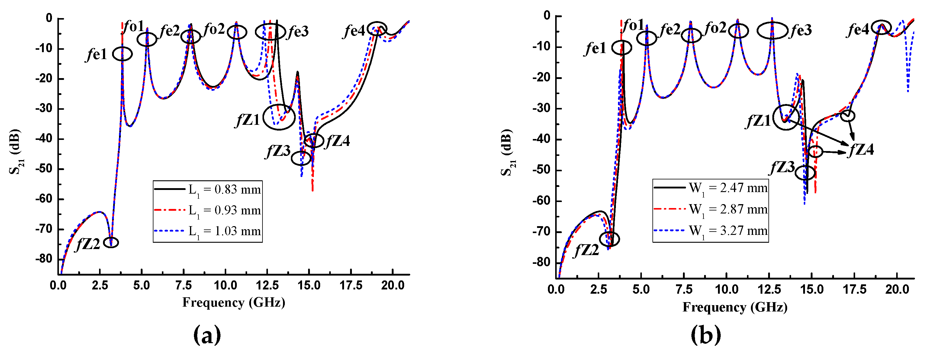
The proposed resonator has many dimension parameters, yet many of them have the same adjustment function. For example, the positions of fe3 and fz1 can be changed by tuning the impedance ratio or electrical length of Stub1. Figure 4a,b shows the adjustment of the low-impedance microstrip line length L1 of Stub1 and the low-impedance microstrip line width W1 (which can also be considered the impedance ratio) of Stub2, respectively. As L1 increases, fe3, fe4 and fz1 gradually shift to low frequencies with the other modes and TZs unchanged. The movement of fe4 is much smaller than that of fe3. The altering of size W1 in Stub1 causes the displacement of fe1, fz2, fz3 and fz4, and fz4 is the most affected. The change of their frequencies is inversely proportional to that of the W1 value. Tuning the length L2 of Stub3 can realize the control of odd modes, particularly fo2.
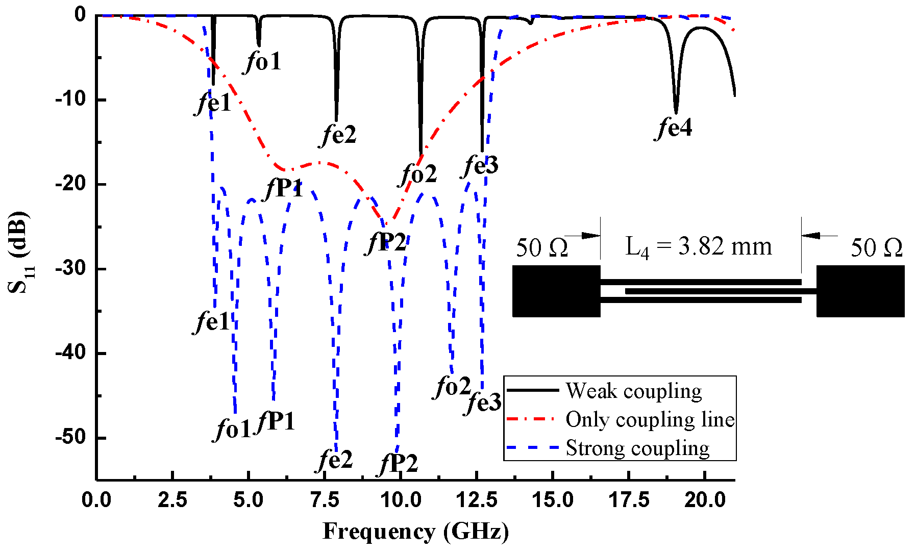
Figure 5 illustrates the reason why five TPs in the passband change to seven in cases of strong coupling. It can be observed from the response curves of the parallel coupling line and quintuple-mode resonator under weak coupling that the TPs fp1 and fp2 generated by the stepped-impedance parallel coupling line are between fo1 and fe2 and between fe2 and fo2, respectively. Because of these two newly added TPs, the reflection of this UWB filter can be further improved under the condition of equal bandwidth. The parallel coupling line with a narrow line width and slot width configuration is utilized to avoid double-sided etching instead of the frequently used aperture structure [8,11,13] and to feed energy into the resonator to realize strong coupling, which simplifies the processing steps and promotes circuit consistency. Moreover, if the circuit is etched on the back of the double-sided YBCO/MgO/YBCO high-temperature superconducting (HTS) films then the grounding treatment between the filter and the metal shielding box will be difficult because the indium film between them will affect the aperture structure.
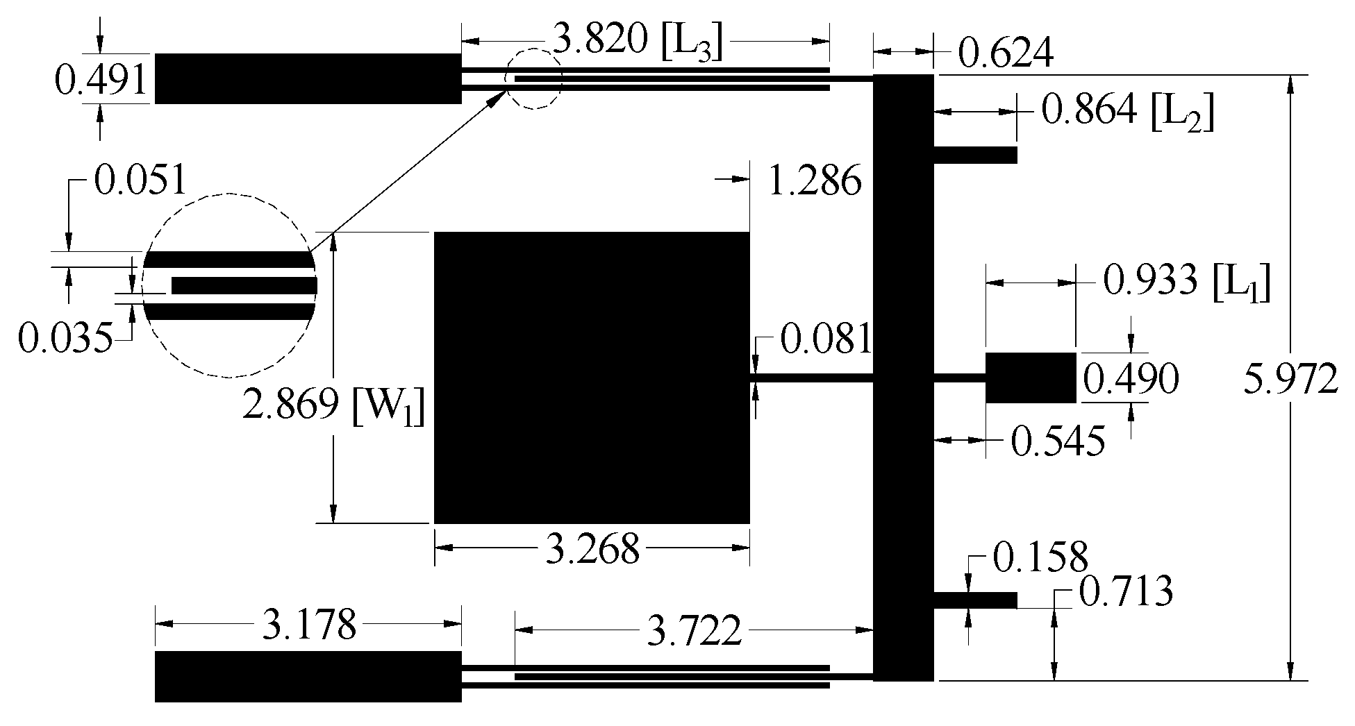
According to the above simulation analysis and the previously determined initial dimensions (especially the critical parameters W1, L1, L2 and L3), the simulation design and optimization are carried out by the full-wave electromagnetic simulation software IE3D. The substrate is MgO with a thickness of 0.5 mm and a dielectric constant of 9.8. The final circuit is presented in Figure 6, and all the size parameters have been marked in the figure (unit: millimeters).

3. Fabrication and Measurement of UWB Filter

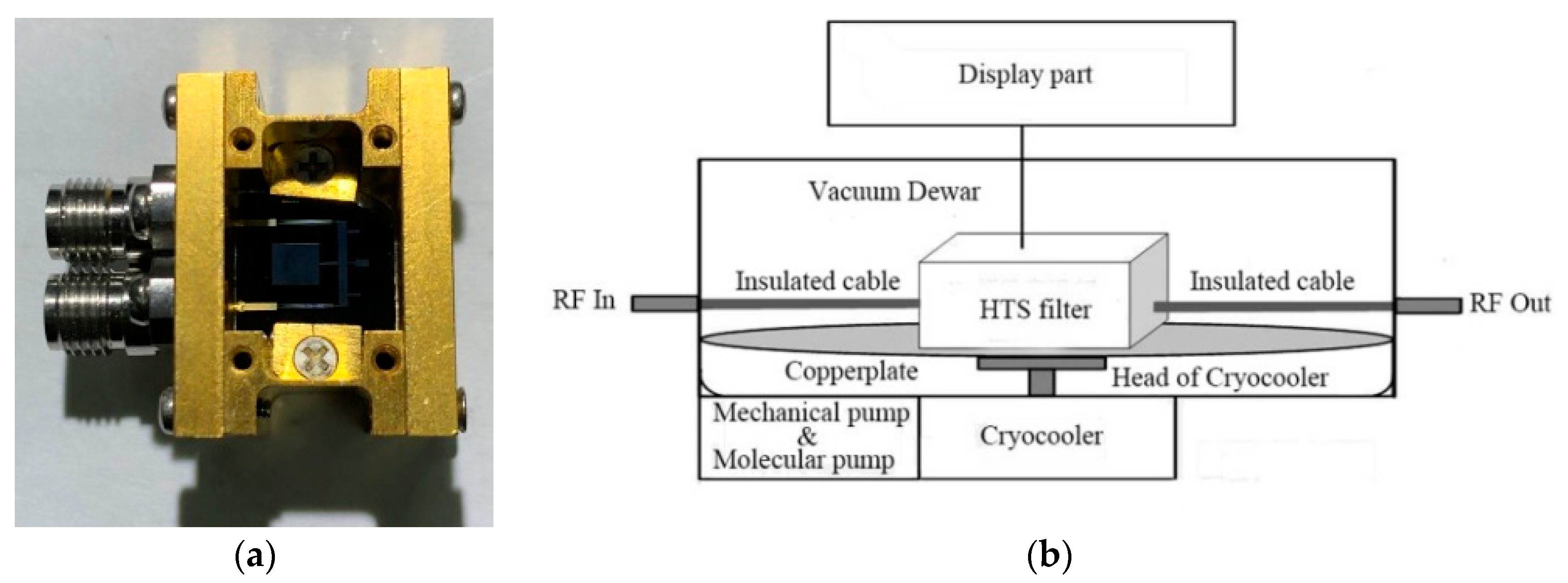
Using high-precision lithography technology, the remaining YBCO film except the filter pattern on one side of the double-sided YBCO/MgO/YBCO superconducting film was ablated by the laser in accordance with the mask plate of the filter circuit, while the other side was connected to the metal shielding box as the circuit ground. In order to ensure good contact between the ground, we put indium film between the metal box and superconducting film and the shielding box was plated with gold for preventing oxidation. The gold on the input and output 50 Ω line of the filter was reserved for good electrical connection between the pins of the connectors and the input and output ports. The dimension of the whole filter was 9.55 × 6.38 × 0.50 mm3 with the connectors removed. The size of the shielding box was optimized in simulation for moving its resonances outside the test band. If the filter coupled to box resonances during the measurement, absorbing materials could be pasted on the top metal cover to eliminate the interference of resonant frequencies. Figure 7a shows the photograph of the fabricated UWB filter without a metal cover.
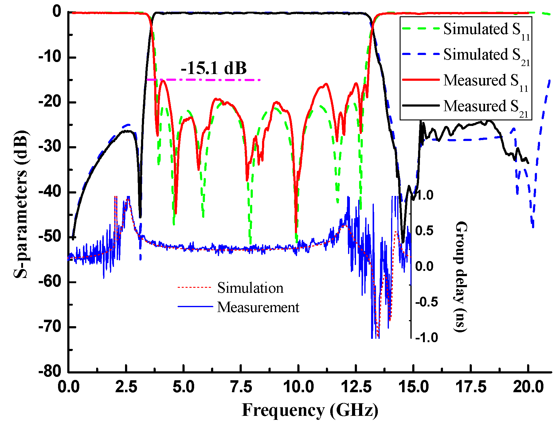
The HTS UWB filter was measured with a cover on, using a low-temperature test system, as shown in Figure 7b. The test procedures were as follows: firstly, the HTS filter on the copper plate was fixed in the dewar, and the insulation cables were connected to the filter connectors; the dewar was sealed, and the mechanical pump and molecular pump were used to pump it into a vacuum state. Subsequently, the cryocooler was turned on, cooling the filter to the superconducting conversion temperature of 70 K. The display module displayed the temperature of the filter in real time. Finally, the vector network analyzer was connected to the RF input and output of the test system. Figure 8 shows the measured and simulated response curves and illustrates that they were in good agreement. The 3-dB passband covered the range of 3.6–13.2 GHz, and the fractional bandwidth (FBW) was 114.3%. The in-band return loss was better than 15.1 dB, and the roll-off rate was up to 56 dB/GHz due to the introduction of TZs at the band edge. The upper stopband with a 20 dB suppression level was extended to 20.8 GHz. Most importantly, the maximum in-band insertion loss was only 0.32 dB. Further, the in-band group delay was about 0.3 ~ 1 ns. Table 1 compares this work with other reported filters. Obviously, the insertion loss, return loss and size of our filter demonstrate great advantages.

4. Conclusions

In this paper, a simple and compact quintuple-mode resonator with a stepped-impedance parallel coupling line was proposed to realize the design of a UWB filter. The properties of each mode in the passband were analyzed using theory and simulation, and several parameters were selected to show their regulating functions on odd/even modes and TZs. Finally, HTS material was used to process the proposed UWB filter for achieving its optimal performance. The test results verify the feasibility of the design and the accuracy of the simulation.

Author Contributions

Conceptualization, methodology, software, L.Z.; formal analysis, writing—original draft preparation, Z.L.; review and editing, H.W.; visualization, H.L.; supervision, T.Z.

Funding

This research received no external funding.

Acknowledgments

The authors acknowledge the support of the school of Aeronautics and Astronautics, University of Electronic Science and Technology of China.

Conflicts of Interest

The authors declare no conflict of interest.

References

  1. Zhu, L.; Sun, S.; Menzel, W. Ultra-wideband (UWB) bandpass filters using multiple-mode resonator. IEEE Microw. Wirel. Compon. Lett. 2005, 15, 796–798. [Google Scholar]
  2. Gao, X.; Feng, W.; Che, W. Compact ultra-wideband bandpass filter with improved upper stopband using open/shorted stubs. IEEE Microw. Wirel. Compon. Lett. 2017, 27, 123–125. [Google Scholar] [CrossRef]
  3. Kamma, A.; Das, R.; Bhatt, D.; Mukherjee, J. Multi mode resonators based triple band notch UWB filter. IEEE Microw. Wirel. Compon. Lett. 2017, 27, 120–122. [Google Scholar] [CrossRef]
  4. Kumar, S.; Gupta, R.D.; Parihar, M.S. Multiple band notched filter using C-shaped and E-shaped resonator for UWB applications. IEEE Microw. Wirel. Compon. Lett. 2016, 26, 340–342. [Google Scholar] [CrossRef]
  5. Riaz, M.; Virdee, B.S.; Shukla, P.; Onadim, M. Quasi-elliptic ultra-wideband bandpass filter with super-wide stopband. AEU-Int. J. Electron. Commun. 2019, 105, 171–176. [Google Scholar] [CrossRef] [Green Version]
  6. Sahin, E.G.; Gorur, A.K.; Karpuz, C.; Gorur, A. Design of UWB microstrip bandpass filter using stub-loaded quintuple-mode resonator. Microw. Opt. Technol. Lett. 2016, 58, 662–666. [Google Scholar] [CrossRef]
  7. Sarkar, D.; Moyra, T.; Murmu, L. An ultra-wideband (UWB) bandpass filter with complementary split ring resonator for coupling improvement. AEU-Int. J. Electron. Commun. 2017, 71, 89–95. [Google Scholar] [CrossRef]
  8. Yan, T.; Lu, D.; Tang, X.-H.; Xiang, J. High-selectivity UWB bandpass filter with a notched band using stub-loaded multi-mode resonator. AEU-Int. J. Electron. Commun. 2016, 70, 1617–1621. [Google Scholar] [CrossRef]
  9. Zhou, C.-X.; Guo, P.-P.; Zhou, K.; Wu, W. Design of a compact UWB filter with high selectivity and superwide stopband. IEEE Microw. Wirel. Compon. Lett. 2017, 27, 636–638. [Google Scholar] [CrossRef]
  10. Deng, H.-W.; Zhao, Y.-J.; Zhang, L.; Zhang, X.-S.; Gao, S.-P. Compact quintuple-mode stub-loaded resonator and UWB filter. IEEE Microw. Wirel. Compon. Lett. 2010, 20, 438–440. [Google Scholar] [CrossRef]
  11. Zhu, H.; Chu, Q.-X. Compact ultra-wideband (UWB) bandpass filter using dual-stub-loaded resonator (DSLR). IEEE Microw. Wirel. Compon. Lett. 2013, 23, 527–529. [Google Scholar] [CrossRef]
  12. Kim, C.H.; Chang, K. Ultra-wideband (UWB) ring resonator bandpass filter with a notched band. IEEE Microw. Wirel. Compon. Lett. 2011, 21, 206–208. [Google Scholar] [CrossRef]
  13. Zhu, H.; Chu, Q.-X. Ultra-wideband bandpass filter with a notch-band using stub-loaded ring resonator. IEEE Microw. Wirel. Compon. Lett. 2013, 23, 341–343. [Google Scholar] [CrossRef]
  14. Long, Z.; Tian, M.; Zhou, L.; Cao, S.; Qiao, M.; Zhang, T. HTS Multi-Mode Ring Resonator UWB Filter with Cross-Shaped Stepped-Impedance Stubs. Prog. Electromagn. Res. 2018, 78, 129–134. [Google Scholar] [CrossRef] [Green Version]
  15. Zhang, T.; Tian, M.; Long, Z.; Qiao, M.; Fu, Z. High-Temperature Superconducting Multimode Ring Resonator Ultrawideband Bandpass Filter. IEEE Microw. Wirel. Compon. Lett. 2018, 28, 663–665. [Google Scholar] [CrossRef]
  16. Lin, H.; Xia, X.; Guo, Z.; Jin, H.; Yang, T. Compact high selectivity UWB filter using composite CPW-microstrip structure. IEICE Electron. Express 2016, 13, 20161049. [Google Scholar] [CrossRef] [Green Version]
  17. Honari, M.M.; Mirzavand, R.; Saghlatoon, H.; Mousavi, P. Two-layered substrate integrated waveguide filter for UWB applications. IEEE Microw. Wirel. Compon. Lett. 2017, 27, 633–635. [Google Scholar] [CrossRef]
  18. Shang, Z.; Guo, X.; Cao, B.; Wei, B.; Zhang, X.; Yong, H.; Suo, G.; Song, X. Design of a Superconducting Ultra-Wideband (UWB) Bandpass Filter With Sharp Rejection Skirts and Miniaturized Size. IEEE Microw. Wirel. Compon. Lett. 2013, 23, 72–74. [Google Scholar] [CrossRef]
  19. Wang, L.-M.; Lin, W.-C.; Chang, M.-L.; Shiau, C.-Y.; Wu, C.-T. Characteristics of ultra-wideband bandpass YBCO filter with impendence stub. IEEE Trans. Appl. Supercond. 2010, 21, 551–554. [Google Scholar] [CrossRef]
Figure 1. Evolution process of the triple-mode stepped-impedance resonator (SIR) to the quintuple-mode resonator.
Electronics 08 01473 g001
Figure 2. Equivalent transmission line circuits. (a) Odd mode. (b) Even mode.
Electronics 08 01473 g002
Figure 3. Function of each section of UWB filter.
Electronics 08 01473 g003
Figure 4. Adjustment of key dimension parameters. (a) Low-impedance microstrip line length L1 of Stub1. (b) Low-impedance microstrip line width W1 of Stub2.
Electronics 08 01473 g004
Figure 5. Evolution of TPs due to the parallel coupling line.
Electronics 08 01473 g005
Figure 6. Designed ultra-wide band (UWB) filter circuit.
Electronics 08 01473 g006
Figure 7. Measurement of the fabricated UWB filter: (a) the fabricated high-temperature superconducting (HTS) filter, and (b) the low-temperature test system architecture.
Electronics 08 01473 g007
Figure 8. Measured and simulated results.
Electronics 08 01473 g008
Table 1. Comparison with other reported filters.
Ref.IL (dB)RL (dB)S.F.
S . F . = Δ f 3 d B Δ f 30 d B
3-dB FBW (%)Size (λg0 × λg0)ComplexityMaterial
[2]<1.0010.50.722123.00.17 × 0.14ComplexCopper
[5]0.4@f011.5N/A103.40.46 × 0.16SimpleCopper
[9]<1.6012.00.920110.10.60 × 0.54SimpleCopper
[15]<0.7510.70.910122.31.53 × 0.45ComplexHTS
[17]<1.0014.00.682110.0N/AComplexCopper
[18]<1.3010.60.968111.01.48 × 0.81SimpleHTS
[19]<0.8810.5N/A96.40.28 × 0.28SimpleHTS
This work<0.3215.10.872114.30.24 × 0.16SimpleHTS
IL: maximum in-band insertion loss; RL: return loss; S.F.: selectivity factor of the passband; ∆f3dB, ∆f30dB: 3-dB bandwidth and 30-dB bandwidth of the passband, respectively; 3-dB FBW: 3-dB fractional bandwidth of passband; λg0: free space wavelength at the center frequency.