Article

Lifetime Estimation and Failure Risk Analysis in a Power Stage Used in Wind-Fuel Cell Hybrid Energy Systems

by
Sima Rastayesh
1,*,
Sajjad Bahrebar
2,
Amir Sajjad Bahman
3,
John Dalsgaard Sørensen
1 and
Frede Blaabjerg
3
1
Department of Civil Engineering, Aalborg University, 9220 Aalborg Ø, Denmark
2
Department of Mechanical Engineering, Technical University of Denmark, 2800 Kongens Lyngby, Denmark
3
Department of Energy Technology, Aalborg University, 9220 Aalborg, Denmark
*
Author to whom correspondence should be addressed.
Electronics 2019, 8(12), 1412; https://doi.org/10.3390/electronics8121412
Submission received: 25 October 2019 / Revised: 11 November 2019 / Accepted: 23 November 2019 / Published: 26 November 2019
(This article belongs to the Section Power Electronics)

Abstract

:
This paper presents a methodology based on the failure mode and effect analysis (FMEA) to analyze the failures in the power stage of wind-fuel cell hybrid energy systems. Besides, fault tree analysis (FTA) is applied to describe the probabilistic failures in the vital subcomponents. Finally, the reliability assessment of the system is carried out for a five-year operation that is guaranteed by the manufacturer. So, as the result, the reliability analysis proves that the metal oxide semiconductor field effect transistor (MOSFET) and electrolytic capacitor are the most critical components that introduce damages in the power circuit. Moreover, a comparative study on the reliability assessment by the exponential distribution and the Weibull distribution show that the B1 lifetime obtained by the Weibull distribution is closer to reality.

1. Introduction

Renewable energy systems are rapidly growing in the power sector industry, such as wind turbines, solar energy, and also fuel cells [1,2,3,4]. Renewable energy sources are proliferating even more than the expected estimations, although each has its pros and cons. For instance, wind turbines are dependent on wind means climate condition, while fuel cells demand hydrogen-rich fuel. Furthermore, one tricky issue is to keep power production stable; hybrid energy systems facilitate such disadvantages [5,6]. A hybrid wind-fuel cell system usually includes a wind turbine, proton exchange membrane fuel cells (PEMFC), ultracapacitor, an electrolyzer, and a power convertor. Wind turbine power output variations because of wind speed change could be reduced by a fuel cell stack. In this system, the wind turbine and the fuel cell supply the load simultaneously; in order to save extra energy produced by the wind turbine when wind is over speeding, it is converted to hydrogen utilizing an electrolyzer to be used in the fuel cell when needed. Minimizing voltage fluctuations in the system and generating AC voltage are, respectively, the ultracapacitors and the power converter functions [7,8]. PEMFC is a kind of fuel cell being developed by General Electric Corporation as a renewable energy system in many applications, such as transportation, stationary applications, and portable applications, as well as hybrid energy systems [9,10]. Generally, PEMFCs are divided into three main subsystems that contain: Power conditioner, stack, and balance of plant (BoP) [11]. A power conditioner is one of the crucial subsystems, in which the DC/DC converter regulates the output from the PEMFC stack to a fixed DC voltage [12]. The power stage component is a critical part of the power conditioner subsystem in a PEMFC system which includes active and passive subcomponents. Active subcomponents consist of primary metal oxide semiconductor field effect transistors (MOSFETs) and secondary MOSFETs, which both could contain eight transistors, and their functions are to control the electrical current, voltage regulation, boost switching, and also rectification. Besides, there are passive subcomponents including: Input and output electrolyte capacitors, transformer, choke, varistor, shunt resistor, fuse, and heatsink. The functions of these components are filtering, transmission of current and voltage, and interconnection between different components. MOSFETs as active subcomponents and electrolytic capacitors as passive subcomponents are more significant due to their functions and applications. MOSFETs are used as a switch where the electrical current passes at a desired time interval. In addition, electrolyte capacitors work as a storage for the electrical energy and stabilization of the current voltage [13,14,15]. There are many studies of capacitors’ reliability and failure analysis [16,17,18] and this paper focuses on the MOSFET as a critical active subcomponent in the power stage and carrying out a diverse failure mechanism analysis of it by failure mode and effect analysis (FMEA) technique.
Achieving a product that can meet customers’ demands with the best design, construction, production, and operation costs is one of the main goals in all industries [19,20]. Reliability is a critical criterion of a product’s performance, expressed in both deterministic and probabilistic approaches. In the deterministic expression, failure modes and mechanisms are often discussed based on observations, while in the probabilistic case, the failure issues are studied based on statistics [21]. Function investigations and analysis of each system require an individual function analysis of each component, its subsets, and their interaction. The advantages and disadvantages of a component entirely depend on the subsets it is used in. Evidently, the use of defective components with a short lifetime will reduce the efficiency and lifetime of the component and the main system. Therefore, prior to the reliability evaluation of a system, its related components, and failure modes, as well as failure mechanisms of its components and even critical subcomponents, should be adequately comprehended [22].
The literature review shows that the FMEA method is an essential step in conducting a failure mode and failure mechanisms evaluation [11,23]. The FMEA method has been used in multiple types of industry and it is based on discovering, arranging, and decreasing the failures or faults. The majority of the literature available on the PEMFC systems have performed a brief study about failure modes and failure mechanisms [24,25,26], also most studies were on system-level and non-electrical parts of the PEMFC system, such as electrochemical parts, BoP, and stack part [27,28,29]. Reliability, availability, and risk study of different parts of the PEMFC are important issues that should be assessed completely. For system recognition, there are main steps, which are significant for the identification of the systems and it is the basis for this study. FMEA focuses on prevention by facilitating process improvement and identifying and eliminating concerns as well as the development of a process or design [30].
Fault tree analysis (FTA) is used for reliability assessment of a system. The fault tree approach is a deductive process by means of which an undesirable event, called the top event, is postulated, and the possible ways for this event to occur are systematically deduced. The deduction process is performed so that the fault tree embodies all component failures (i.e., failure modes) that contribute to the occurrence of the top event. The fault tree itself is a graphical representation of the various combinations of failures that led to the occurrence of the top event [31]. The fault tree itself is a logical model, and thus represents the qualitative characterization of the system logic. There are, however, many quantitative algorithms to evaluate fault trees. For example, the concept of cut sets can also be applied to fault trees by using the Boolean algebra method. This methodology has been used in several applications as well as PEMFCs [32,33]. The focus of the FTA suggested in this paper is the failure of power stage as the top event by considering filters as input and output.
In this paper, the FMEA method is used for the power stage component as a central part of the power conditioner subsystem of a PEMFC system. FMEA as a technique in reliability analysis is used to rank the estimated risk priority with various potential failure modes for critical subcomponents and potential failure modes/mechanisms. According to the FTA of the power stage, it is demonstrated how the failure could happen. Furthermore, with the use of exponential and Weibull distributions by applying Monte Carlo simulation, the reliability is estimated and the reliability curve is presented within the 5-year guarantee period for the system analyzed.

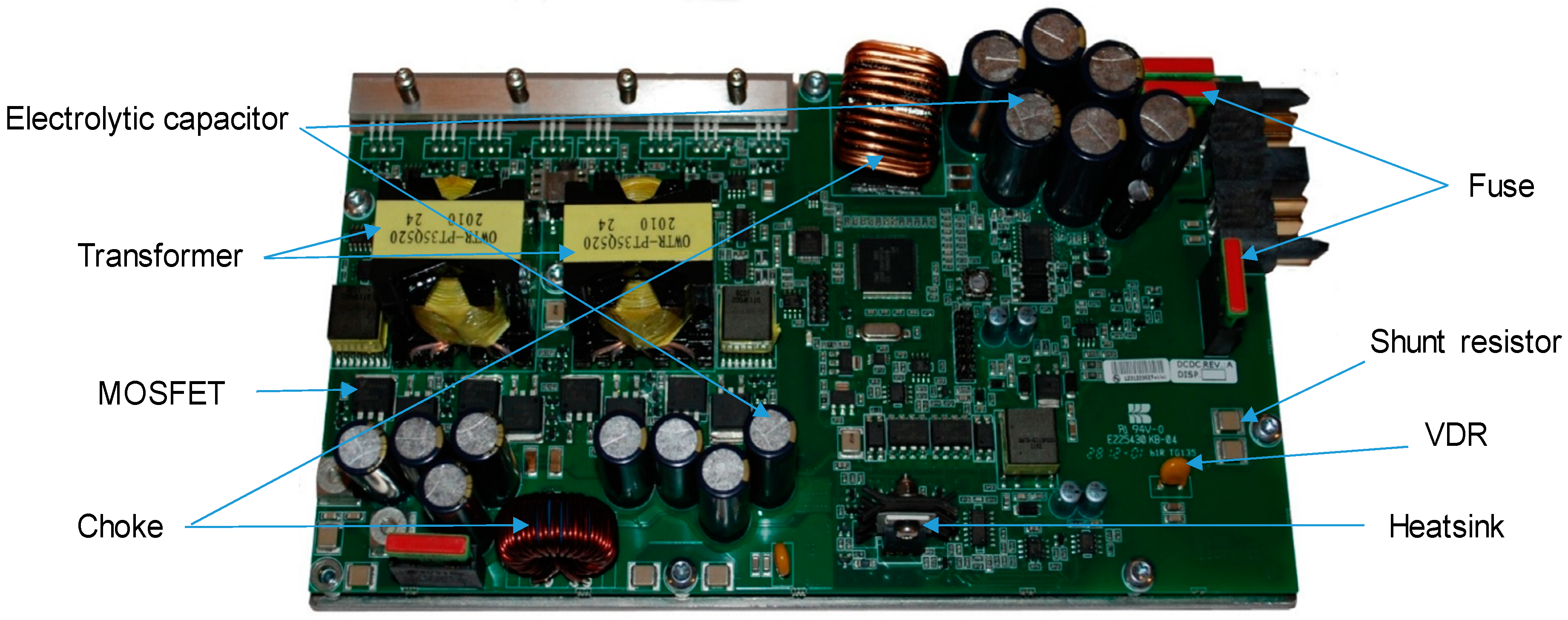
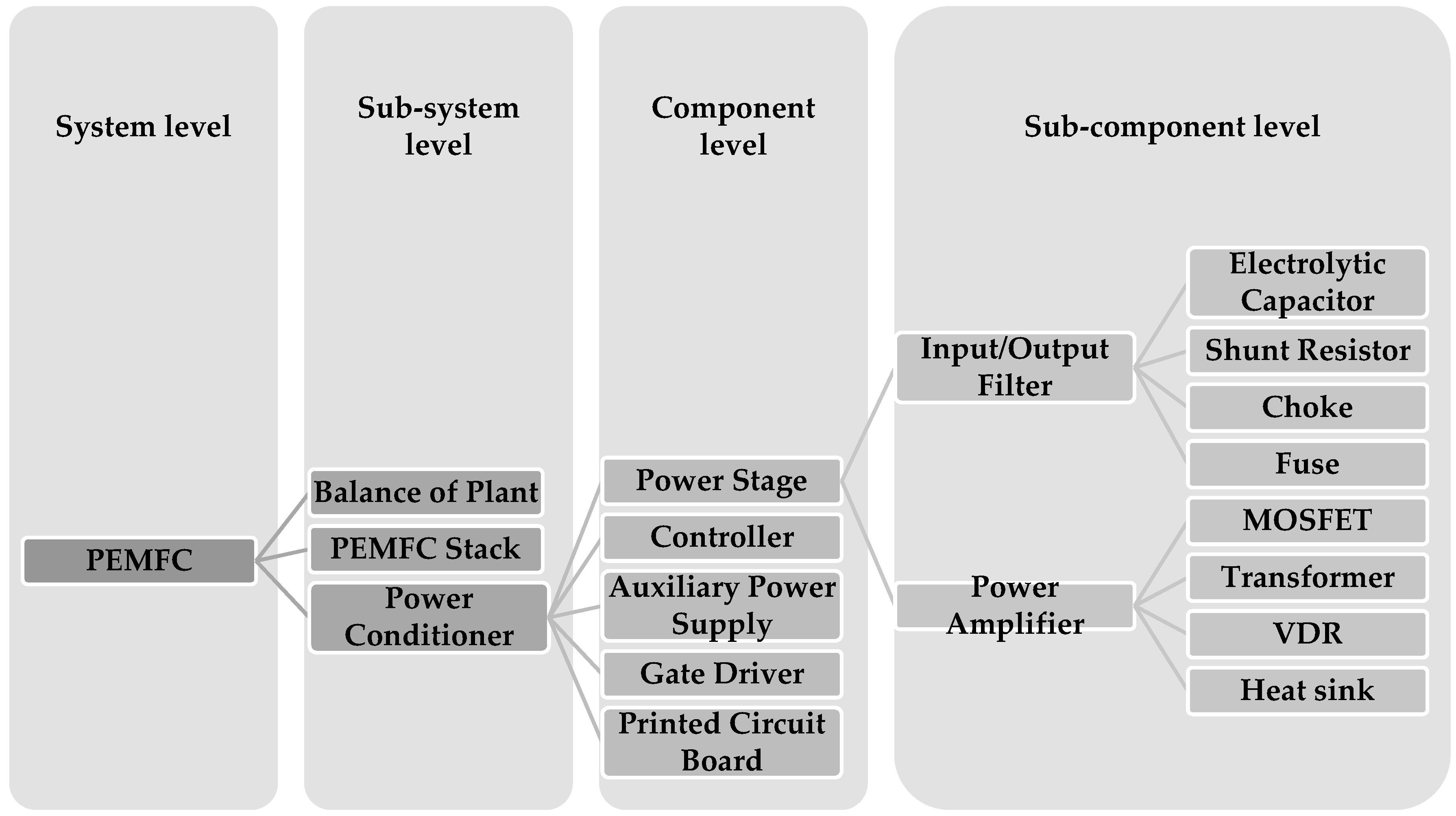
2. Power Stage Components

In the wind-fuel cell system as a hybrid energy system application, the power conditioner subsystem of a PEMFC system carries out the primary power conversion from the input voltage to the output voltage. Usually, a power stage has three parts: Input filter, power amplifier, and output filter. MOSFETs are used as an active subcomponent and it are significant and important due to functions and applications. The power amplifier contained in this case is sixteen MOSFETs used as switches and rectifier where the electrical current is conducted at the desired time interval. Besides, two transformers are used to isolate the primary and secondary sides and to store transient energies during transients.
Furthermore, a voltage dependent resistor (VDR) or varistor is used as control/limit for excessive transient voltage. Both the input filter and the output filter contain the fuse, choke, shunt resistor, and an electrolytic capacitor. A shunt resistor functions as a type of current sensor used in the power stage [13,34]. The schematic of the PEMFC’s different levels and all of the main elements of the power stage are depicted and identified in Figure 1 and Figure 2, respectively.

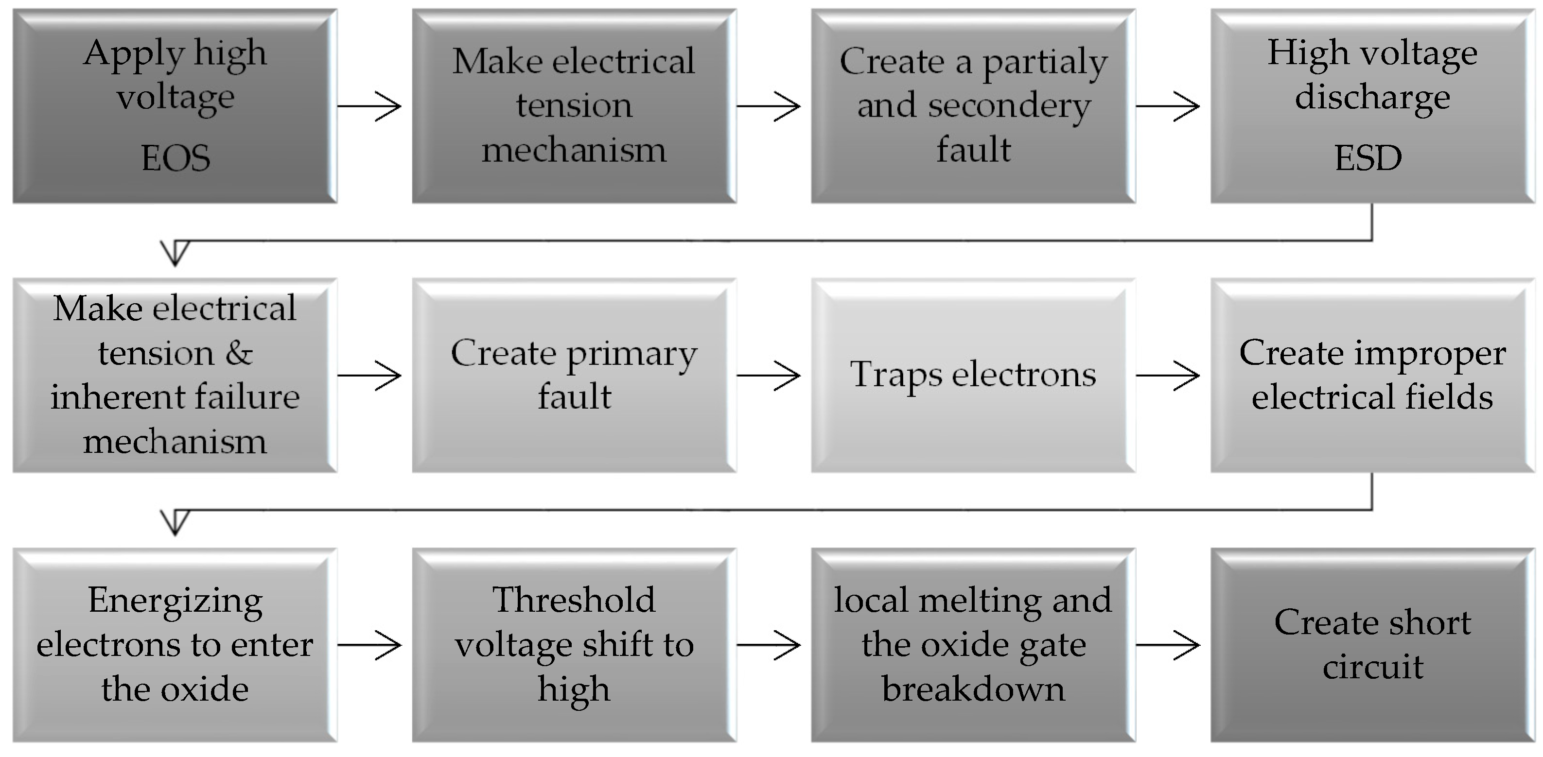
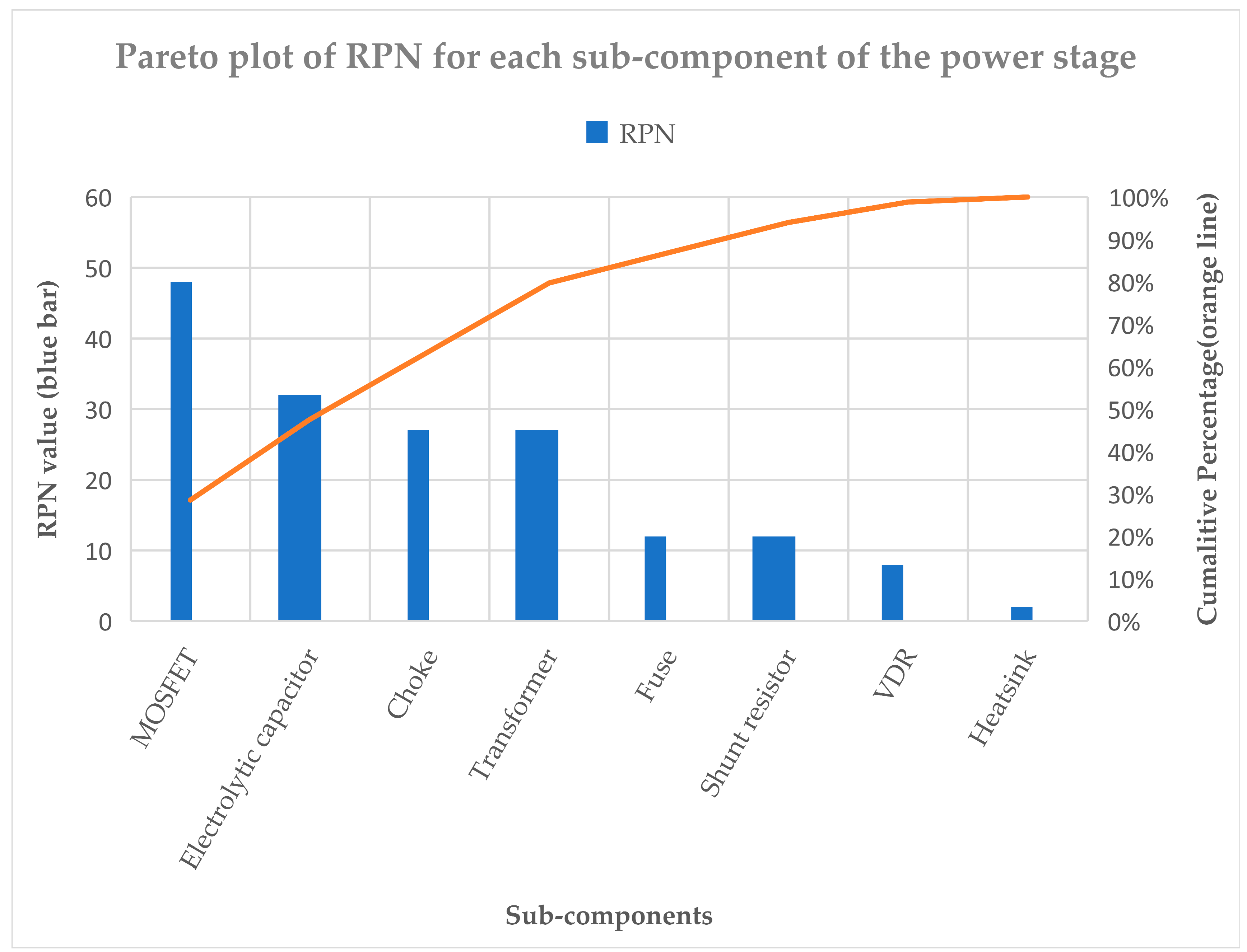
3. Failure Mechanisms and Failure Modes Analysis

Each system has internal durability that may be varied due to particular internal or external circumstances. Failure occurs when exerted stress exceeds the capacity of a system [35]. Failure mechanisms are physical processes that cause failures or stress that, in turn, reduce the stability of the system [36]. These mechanisms are different for mechanical and electrical equipment [37]. Mechanical failure mechanisms can generally be divided into three categories: Tension creation, strength reduction, and stress increase. However, the failure mechanism in electrical equipment is more complicated than that of mechanical failure mechanism due to the complexity of electrical assemblies, which can be divided into three general categories of electrical stress (tension), inherent failure, and external failure. Each of these mechanisms will cause a functional problem and reduce the reliability [38].
First, electrical tension mechanism: Application of an exceeded voltage or current intensity to an electrical component leads to stress creation, reduced performance, or degradation. Additionally, extreme electrical currents increase the heat and local melting at sensitive points of the circuit, which often result in the catastrophic failure or hidden damages of the circuit [21,39], such as failure mechanism type of the MOSFETs and the electrolytic capacitors.
Second, inherent failure mechanism: This mechanism is related to the electronic component itself. These kinds of failure mechanisms are often related to semiconductor components/chips and the growth of active electrical layers on their surface. In general, the inherent failure mechanisms include ion contamination, gate oxide breakdown, surface charge spreading, and hot electrons [21,39]. These failures often occur due to weaknesses in the manufacturing process or incomplete print design techniques.
Third, external failure mechanism: This failure mechanism generally occurs because of external factors, such as mounting and packaging problems, and the way of connecting with other components in the unit or system environmental effects [39]. Today, due to the growth of knowledge and technology in the design and manufacturing of electronic components, external failures are more important than the inherent failure of the components. Die attachment failure, electron migration, corrosion, radiation, and internal connection failures are among common failure mechanisms of external failure in the electronic components.
Applying an exceeded voltage to the MOSFET as a top subcomponent of the power stage in a circuit is a partial and secondary fault. However, the existence of electrostatics because of high voltage discharge in this element is a partial and primary fault, leading to local melting and the oxide gate’s breakdown. Both conditions, i.e., the electrostatic discharge (ESD) and the electrical over stress (EOS), are included in a subset of failures due to electrical stresses. Because of improper processing of the oxide gate or mentioned electrical stresses, differences appear in voltage and current characteristics of the MOSFET. This defect, comprising an intrinsic failure mechanism and electrical stress, traps electrons at the common interface of the oxide gate, creating improper electrical fields and energizing electrons to enter the oxide, resulting in a threshold voltage shift and short circuit. This failure mechanism steps as an instance on the critical active subcomponent of the power stage as illustrated in Figure 3.
FMEA is an important step in the reliability assessment. The design is the primary objective of the FMEA. Another objective of the FMEA is to identify and classify the potential risk of components [40]. It can support the fault-tolerant plan, testability, security, logistic patronage, and pertaining functions for system FMEAs; the aim is to review the design and predict the damage to the system. Improvements of the test and verification of the plans are other targets of the FMEA [41]. Figure 4 shows the process of an FMEA for the power stage in the PEMFC. This methodology could be applied in the state-of-the-art of the PEMFC industry in order to overcome shortages in identifying the critical failure mechanism for each component. Occurrence (O), Detectability (D), and Severity (S) are used in the FMEA methods as three risk factors. Input parameters of three factors are scored by a four-point scale to classify different failures, depending on the case study [42]. Based on Table 1, Table 2 and Table 3, scale factors start from one to four shown in the ranking, specified for very low to high risk, respectively. Table 1, Table 2 and Table 3 show the O, D and S classification respectively [43,44]. Table 4 is the FMEA table with the top functions, failure modes, failure cause, failure mechanism, and mechanism type, as well as risk priority number (RPN) as an initial estimation of risk of subcomponents of the power stage in a PEMFC system [45,46].
By implementation of the FMEA and using the scales for severity (S), occurrence (O), and detection (D) factors and by multiplying these input factors [44], the highest risk priority percentage for each subcomponent of the power stage is recognized, which is demonstrated in the Pareto plot of RPN for each subcomponent for a power stage, as shown in Figure 5. As it can be seen, MOSFET and electrolyte capacitor are the most effective on reliability and lifetime of the power stage with around 50% risk. Furthermore, other subcomponents, like transformer and choke, are in the less priority level for risk analysis; that is why they are not considered in following sections.

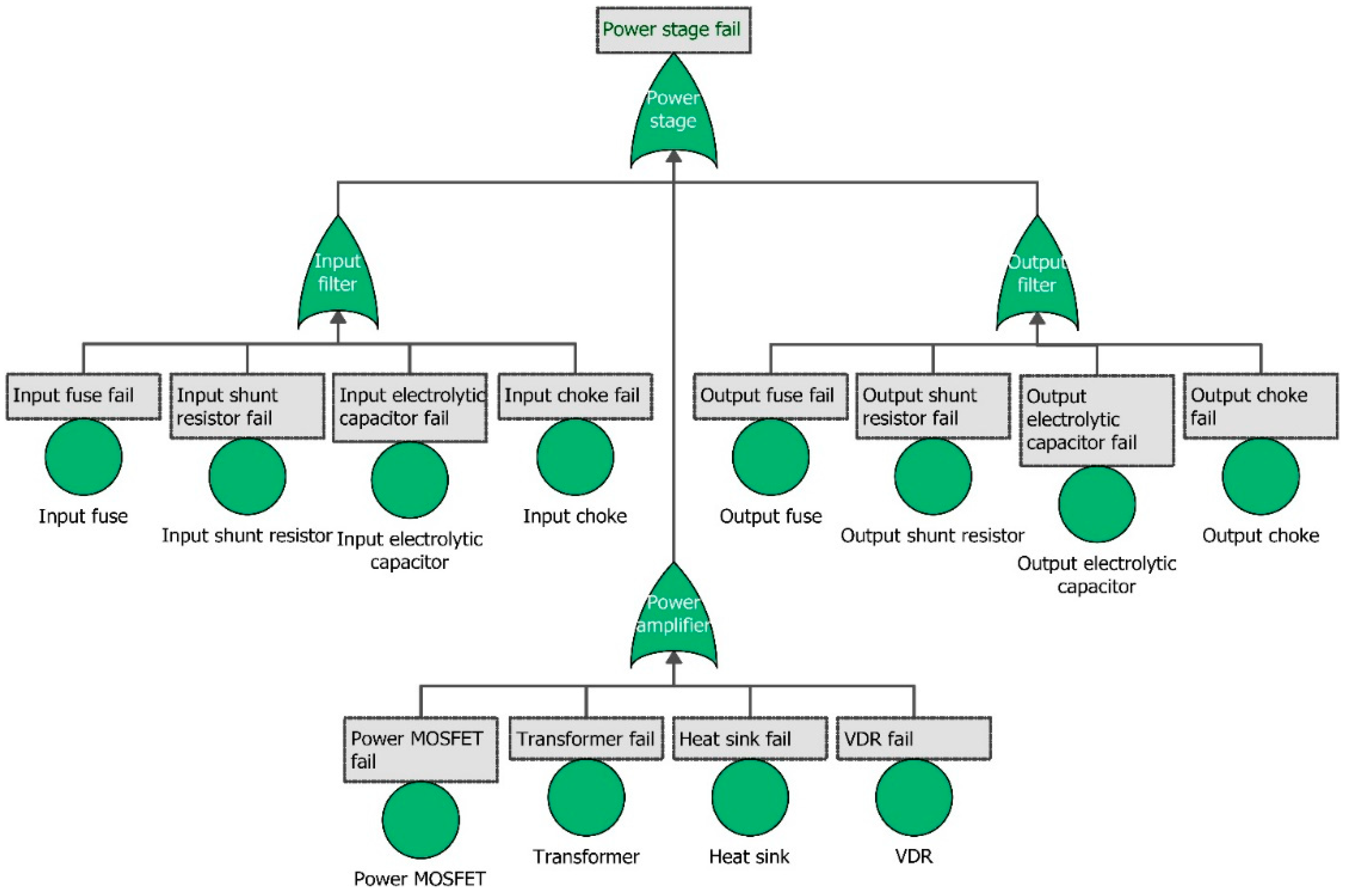
4. Fault Tree Analysis

This section is dedicated to introducing failures of the power stage, where the relationship among their subcomponents is delineated by means of the fault tree. The FTA is a deductive method based on the assumption of an unacceptable situation or an event contrary to the main purpose of the system. This unacceptable situation/event is called the “top event”. In the analysis of the fault tree, it is required to distinguish a component fault from a system fault that results from more than one component [33,47]. Also, the classification of failures into primary and secondary categories will be advantageous in the estimation of the fault tree. That means primary failures include occurrence under normal/tolerable (designed) system conditions, while secondary failures occur in a component and in a state that the system is not designed, and they are usually caused by inappropriate external conditions [48]. The fault tree of the power stage is shown in Figure 6.
The investigation is performed through the whole reliability conditions and calculates the results for each component by using the probabilistic reliability generic data of the power stage [7,13]. Using MIL-HDBK-217F (Military Handbook: Reliability Prediction of Electronic Equipment), as well as some physics of failure-based and mission profile-based approaches [12], all data are collected for the FTA. Reliability of exponential distribution is given by Equation (1):
R ( t ) = e x p ( λ . t )
where, R ( t ) is the reliability over time t , and λ is the failure rate. Moreover, reliability of Weibull distribution is given by Equation (2):
R ( t ) = e x p [ ( t ɳ ) β ]
where, β is the shape parameter, and the scale parameter is ɳ . The shape parameter is also known as the Weibull slope [49,50]. It should be mentioned that by considering β equals 1 in the Weibull distribution, it would be exactly an exponential distribution, which can show the useful life part of the bathtub curve throughout the product lifecycle failure rate, Equation (3).
λ = β ɳ · ( t ɳ ) β 1 if   β = 1 ɳ = 1 λ
Table 5 illustrates all critical subcomponents of the power stage with their failure rates and Weibull parameters, calculated based on Equation (3).

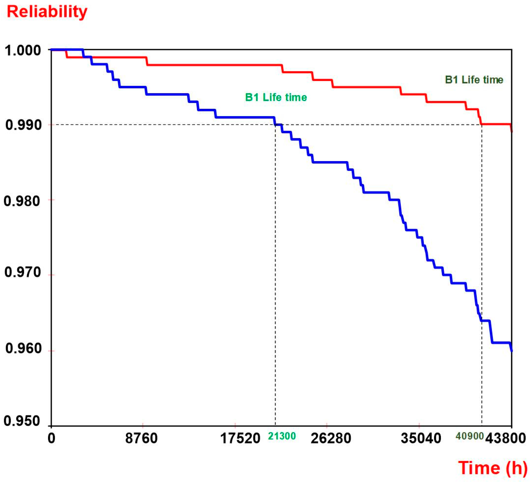
5. Results and Discussion of Reliability Analysis

The reliability curve in Figure 7 shows the system reliability along with time when the reliability is the probability of the system not failed by time. The reliability is calculated by implementing Monte Carlo simulation with point results every 100 h with start time 1 h and end time five years for 1000 number of simulations of the system using the ReliaSoft BlockSim software package. The reliability curve of the power stage, along with the operating years, is illustrated in Figure 6. It is noted that the B1 lifetime is estimated at 21,300 h (887.5 days) in the case of a shape parameter one (β = 1) for all of components shown in Table 2, which is illustrated with the blue color. However, reliability curve with the red color shows B1 at 40,900 h (1704 days) because it has different shape parameters estimated just for MOSFET and electrolytic capacitor; their shape parameter values are taken from [7], 2.59 and 1.93, respectively. Hence, scaling parameters are estimated 1.61× 10⁶ for the MOSFET and 2.18× 10⁶ for the electrolytic capacitor. In fact, this figure clearly illustrates more realization in comparison with not considering Weibull distribution for reliability analysis. In other words, the obtained reliability curve of the system from the Weibull data is very close to the reality experienced in the system.
Consequently, failure analysis shows that two subcomponents of the power stage, which contains MOSFET as an active component and electrolytic capacitor as a passive component, have the most effect on the changes of the reliability as well as the critical failure and hidden damages to the circuit of the system as discussed and demonstrated before in the Pareto plot (Figure 5) from risk analysis of each subcomponent of the power stage based on the FMEA technique. By inserting the Weibull parameter (blue curve) for these two components in the reliability analysis, the results are more reasonable rather than exponential distribution (red one).
The results of the proposed methodology are comparable and complementary with the results of other methodologies. For example, considering the critical power electronic components, the annual accumulated damage is estimated, due to the real mission profile of the fuel cell system. Then, the Monte Carlo analysis is applied to obtain the Weibull distribution of the power semiconductors lifetime. The presented reliability estimation and findings using FMEA and FTA by assuming Weibull distributions have their pros and cons. For instance, it is more detailed, focusing on subcomponents, components, and system; on the other hand it is more understandable, simple, easy, and faster.

6. Conclusions

This paper has presented a failure mechanism analysis of the power stage components in a hybrid wind-fuel cell system by using the FMEA and the FTA. The FMEA identified and analyzed the failure mechanism of power stage components for selected critical subcomponents, which their failures may have significant effects on the system reliability. Some of the failure modes of an active subcomponent such as MOSFET are switching losses, conduction losses, improper pieces selection, failure to operate as designed, voltage and current fluctuations, fractured, overloading, shock failure, and contact damage. Moreover, some of the failure modes of passive subcomponent like electrolyte capacitors are: Non-amplification, improper pieces selection, failure to function as intended for any piece, voltage, and current fluctuations, breakage, electric current, improper assembly, inadequate support (structural), fractured, loosened, open-circuited, overloading, oxidized, shock failure, short-circuited, contact damage, swells, thinning, distortion, and vibration. Furthermore, the FTA is constructed by considering the results of the FMEA with three significant parts: Input filter, power amplifier, and output filter. The reliability curve of the power stage can be estimated in five years, which is consistent with the defined guarantee period. It is concluded that the B1 lifetime of the power stage is 2.4 years for the same shape parameter (assumed exponential distribution) and 4.7 years for different shape parameters (assumed Weibull distribution), which is closer to real experience. It is recommended to use Weibull distribution for reliability analysis rather than exponential distribution as it leads to more realistic results. Since the Weibull parameters are not usually available for all components or difficult to obtain by reliability tests, FMEA is recommended to distinguish the high-risk components and consequently to find their Weibull parameters for reliability analysis.

Author Contributions

The main idea for the paper was proposed by S.R. S.R. wrote the first draft of the paper, except Section 2, which was drafted by S.B. S.R. and S.B. developed the methodology. S.R. and S.B. post-processed the results. A.S.B., J.D.S., and F.B., supervised the findings of this work and reviewed methodology. All authors contributed for articulating the research work in its current form as a full research manuscript.

Funding

The research leading to these results has been partly conducted under the INFRASTAR (infrastar.eu) project in the field of reliability approaches for decision making for wind turbines and bridges, which has received funding from the European Union’s Horizon 2020 research and innovation program under the Marie Skłodowska-Curie grant agreement No 676139. The grant is gratefully acknowledged.

Conflicts of Interest

The authors declare no conflict of interest.

References

  1. Khan, F.I.; Hawboldt, K.; Iqbal, M.T. Life Cycle Analysis of wind-fuel cell integrated system. Renew. Energy 2005, 30, 157–177. [Google Scholar] [CrossRef]
  2. Eroglu, M.; Dursun, E.; Sevencan, S.; Song, J.; Yazici, S.; Kilic, O. A mobile renewable house using PV/wind/fuel cell hybrid power system. Int. J. Hydrogen Energy 2011, 36, 7985–7992. [Google Scholar] [CrossRef]
  3. Cetin, E.; Yilanci, A.; Ozturk, H.K.; Colak, M.; Kasikci, I.; Iplikci, S. A micro-DC power distribution system for a residential application energized by photovoltaic-wind/fuel cell hybrid energy systems. Energy Build. 2010, 42, 1344–1352. [Google Scholar] [CrossRef]
  4. Iqbal, M.T. Modeling and control of a wind fuel cell hybrid energy system. Renew. Energy 2003, 28, 223–237. [Google Scholar] [CrossRef]
  5. Haddad, A.; Ramadan, M.; Khaled, M.; Ramadan, H.S.; Becherif, M. Triple hybrid system coupling fuel cell with wind turbine and thermal solar system. Int. J. Hydrogen Energy 2019. [Google Scholar] [CrossRef]
  6. Onar, O.C.; Uzunoglu, M.; Alam, M.S. Dynamic modeling, design and simulation of a wind/fuel cell/ultra-capacitor-based hybrid power generation system. J. Power Sources 2006, 161, 707–722. [Google Scholar] [CrossRef]
  7. Khan, M.J.; Iqbal, M.T. Dynamic modeling and simulation of a small wind-fuel cell hybrid energy system. Renew. Energy 2005, 30, 421–439. [Google Scholar] [CrossRef]
  8. Fathabadi, H. Novel standalone hybrid solar/wind/fuel cell/battery power generation system. Energy 2017, 140, 454–465. [Google Scholar] [CrossRef]
  9. Beuscher, U.; Cleghorn, S.J.C.; Johnson, W.B. Challenges for PEM fuel cell membranes. Int. J. Energy Res. 2005, 29, 1103–1112. [Google Scholar] [CrossRef]
  10. Zhang, J. PEM Fuel Cell Electrocatalysts and Catalyst Layers: Fundamentals and Applications; Springer Science & Business Media: Berlin/Heidelberg, Germany, 2008; ISBN 9781848009356. [Google Scholar]
  11. Bahrebar, S.; Blaabjerg, F.; Wang, H.; Vafamand, N.; Khooban, M.-H.; Rastayesh, S.; Zhou, D. A Novel Type-2 Fuzzy Logic for Improved Risk Analysis of Proton Exchange Membrane Fuel Cells in Marine Power Systems Application. Energies 2018, 11, 721. [Google Scholar] [CrossRef]
  12. Zhou, D.; Wang, H.; Blaabjerg, F. Mission Profile Based System-Level Reliability Analysis of DC/DC Converters for a Backup Power Application. IEEE Trans. Power Electron. 2018, 33, 8030–8039. [Google Scholar] [CrossRef]
  13. Zhou, D.; Wang, H.; Blaabjerg, F.; Kor, S.K.; Blom-Hansen, D. System-level reliability assessment of power stage in fuel cell application. In Proceedings of the 2016 IEEE Energy Conversion Congress and Exposition (ECCE), Milwaukee, WI, USA, 18–22 September 2016; pp. 1–8. [Google Scholar]
  14. Bahrebar, S.; Zhou, D.; Rastayesh, S.; Wang, H.; Blaabjerg, F. Reliability assessment of power conditioner considering maintenance in a PEM fuel cell system. Microelectron. Reliab. 2018, 88–90, 1177–1182. [Google Scholar] [CrossRef]
  15. Bahrebar, S.; Blaabjerg, F.; Wang, H.; Zhou, D.; Rastayesh, S. System-level Risk Analysis of PEM Fuel Cell Using Failure Mode and Effect Analysis. In Proceedings of the IRSEC 2018, 5th International Reliability and Safety Engineering Conference, Shiraz, Iran, 9–10 May 2018. [Google Scholar]
  16. Soliman, H.; Wang, H.; Blaabjerg, F. A Review of the Condition Monitoring of Capacitors in Power Electronic Converters. IEEE Trans. Ind. Appl. 2016, 52, 4976–4989. [Google Scholar] [CrossRef]
  17. Wang, H.; Blaabjerg, F. Reliability of Capacitors for DC-Link Applications in Power Electronic Converters—An Overview. IEEE Trans. Ind. Appl. 2014, 50, 3569–3578. [Google Scholar] [CrossRef]
  18. Huai, W.; Liserre, M.; Blaabjerg, F.; De Place Rimmen, P.; Jacobsen, J.B.; Kvisgaard, T.; Landkildehus, J. Transitioning to physics-of-failure as a reliability driver in power electronics. IEEE J. Emerg. Sel. Top. Power Electron. 2014, 2, 97–114. [Google Scholar]
  19. Bahman, A.S.; Jensen, S.M.; Iannuzzo, F. Failure mechanism analysis of fuses subjected to manufacturing and operational thermal stresses. Microelectron. Reliab. 2018, 88–90, 304–308. [Google Scholar] [CrossRef]
  20. Rahimi, T.; Jahan, H.; Blaabjerg, F.; Bahman, A.; Hosseini, S. Fuzzy-Logic-Based Mean Time to Failure (MTTF) Analysis of Interleaved Dc-Dc Converters Equipped with Redundant-Switch Configuration. Appl. Sci. 2018, 9, 88. [Google Scholar] [CrossRef]
  21. Modarres, M.; Kaminskiy, M.; Krivtsov, V. Reliability Engineering and Risk Analysis: A Practical Guide, 3rd ed.; CRC Press: Boca Raton, FL, USA, 2010. [Google Scholar]
  22. Pang, H.; Yu, T.; Song, B. Failure mechanism analysis and reliability assessment of an aircraft slat. Eng. Fail. Anal. 2016, 60, 261–279. [Google Scholar] [CrossRef]
  23. Pandey, A.; Singh, M.; Sonawane, A.U.; Rawat, P.S. FMEA Based Risk Assessment of Component Failure Modes in Industrial Radiography. Int. J. Eng. Trends Technol. 2016, 39, 216–225. [Google Scholar] [CrossRef]
  24. Krishnan, K.J.; Kalam, A.; Zayegh, A. Experimental investigation of H2 generator and PEM fuel cell as a remote area back-up power. In Proceedings of the Procedia Engineering; Elsevier Ltd.: Amsterdam, The Netherlands, 2012; Volume 49, pp. 66–73. [Google Scholar]
  25. Wang, Y.; Liu, H.; Lu, C.; Zhou, B. PEM fuel cell health state assessment using a geometrical approach and mahalanobis distance. In Proceedings of the Proceedings of the World Congress on Intelligent Control and Automation (WCICA), Guilin, China, 12–15 June 2016; pp. 1312–1316. [Google Scholar]
  26. Lee, S.; Zhou, D.; Wang, H. Reliablity assessment of fuel cell system—A framework for quantitative approach. In Proceedings of the ECCE 2016—IEEE Energy Conversion Congress and Exposition, Milwaukee, WI, USA, 18–22 September 2016. [Google Scholar]
  27. Rabbani, A.; Rokni, M. Dynamic characteristics of an automotive fuel cell system for transitory load changes. Sustain. Energy Technol. Assess. 2013, 1, 34–43. [Google Scholar] [CrossRef]
  28. Javed, K.; Gouriveau, R.; Zerhouni, N.; Hissel, D. Improving accuracy of long-term prognostics of PEMFC stack to estimate remaining useful life. In Proceedings of the IEEE International Conference on Industrial Technology, Seville, Spain, 17–19 March 2015; pp. 1047–1052. [Google Scholar]
  29. Whiteley, M.; Fly, A.; Leigh, J.; Dunnett, S.; Jackson, L. Advanced reliability analysis of Polymer Electrolyte Membrane Fuel Cells using Petri-Net analysis and fuel cell modelling techniques. Int. J. Hydrogen Energy 2015, 40, 11550–11558. [Google Scholar] [CrossRef]
  30. Arabian-Hoseynabadi, H.; Oraee, H.; Tavner, P.J. Failure Modes and Effects Analysis (FMEA) for wind turbines. Int. J. Electr. Power Energy Syst. 2010, 32, 817–824. [Google Scholar] [CrossRef]
  31. Vesely, W.E.; Goldberg, F.F. Fault Tree Handbook, 16th ed.; U.S. Government Printing Office: Washington, DC, USA, 1981.
  32. Whiteley, M.; Dunnett, S.; Jackson, L. Failure Mode and Effect Analysis, and Fault Tree Analysis of Polymer Electrolyte Membrane Fuel Cells. Int. J. Hydrogen Energy 2016, 41, 1187–1202. [Google Scholar] [CrossRef]
  33. Collong, S.; Kouta, R. Fault tree analysis of proton exchange membrane fuel cell system safety. Int. J. Hydrogen Energy 2015, 40, 8248–8260. [Google Scholar] [CrossRef]
  34. Pourramazan, A.; Saffari, S.; Barghandan, A. Study of Failure Mode and Effect Analysis (FMEA) on Capacitor Bank Used in Distribution Power Systems. Ijireeice 2017, 5, 113–118. [Google Scholar]
  35. Larrucea, X.; Belmonte, F.; Welc, A.; Xie, T. Reliability Engineering. IEEE Softw. 2017, 34, 26–29. [Google Scholar] [CrossRef]
  36. Mathew, S.; Alam, M.; Pecht, M. Identification of failure mechanisms to enhance prognostic outcomes. J. Fail. Anal. Prev. 2012, 12, 66–73. [Google Scholar] [CrossRef]
  37. Young, A.L.; Hilmas, G.E.; Zhang, S.C.; Schwartz, R.W. Mechanical vs. electrical failure mechanisms in high voltage, high energy density multilayer ceramic capacitors. J. Mater. Sci. 2007, 42, 5613–5619. [Google Scholar] [CrossRef]
  38. Toh, S.L.; Tan, P.K.; Goh, Y.W.; Hendarto, E.; Cai, J.L.; Tan, H.; Wang, Q.F.; Deng, Q.; Lam, J.; Hsia, L.C.; et al. In-Depth Electrical Analysis to Reveal the Failure Mechanisms With Nanoprobing. IEEE Trans. Device Mater. Reliab. 2008, 8, 387–393. [Google Scholar] [CrossRef]
  39. Modarres, M. Risk Analysis in Engineering: Techniques, Tools, and Trends; CRC Press: Boca Raton, FL, USA, 2006. [Google Scholar]
  40. Feili, H.R.; Akar, N.; Lotfizadeh, H.; Bairampour, M.; Nasiri, S. Risk analysis of geothermal power plants using Failure Modes and Effects Analysis (FMEA) technique. Energy Convers. Manag. 2013, 72, 69–76. [Google Scholar] [CrossRef]
  41. Jensen, F.; Morris, A.S.; Levin, M.A.; Kalal, T.T.; Pascoe, N.; Carlson, C. Effective FMEAs; Wiely: Hoboken, NJ, USA, 2012. [Google Scholar]
  42. Berg, F.; Logistics, I.; Komenského, P. FMEA (failure mode and effects analysis) and proposal of risk minimizing in storage processes for automotive. Acta Logist. 2016, 3, 15–18. [Google Scholar]
  43. Rafie, M.; Namin, F.S. Prediction of subsidence risk by FMEA using artificial neural network and fuzzy inference system. Int. J. Min. Sci. Technol. 2015, 25, 655–663. [Google Scholar] [CrossRef]
  44. van Leeuwen, J.F.; Nauta, M.J.; de Kaste, D.; Odekerken-Rombouts, Y.M.C.F.; Oldenhof, M.T.; Vredenbregt, M.J.; Barends, D.M. Risk analysis by FMEA as an element of analytical validation. J. Pharm. Biomed. Anal. 2009, 50, 1085–1087. [Google Scholar] [CrossRef] [PubMed]
  45. Wu, R.; Blaabjerg, F.; Wang, H.; Liserre, M. Overview of catastrophic failures of freewheeling diodes in power electronic circuits. Microelectron. Reliab. 2013, 53, 1788–1792. [Google Scholar] [CrossRef] [Green Version]
  46. Shafiee, M.; Dinmohammadi, F. An FMEA-based risk assessment approach for wind turbine systems: A comparative study of onshore and offshore. Energies 2014, 7, 619–642. [Google Scholar] [CrossRef] [Green Version]
  47. Placca, L.; Kouta, R. Fault tree analysis for PEM fuel cell degradation process modelling. Int. J. Hydrogen Energy 2011, 36, 12393–12405. [Google Scholar] [CrossRef]
  48. Rastayesh, S.; Bahrebar, S. Importance Analysis of a Typical Diesel Generator Using Dynamic Fault Tree. Int. J. Curr. Life Sci. 2014, 4, 697–700. [Google Scholar]
  49. Rastayesh, S.; Bahrebar, S.; Sepanloo, K. Time Dependent Reliability Of Emrgency Diesel Generator Station. Indian J. Sci. Res. 2014, 1, 453–460. [Google Scholar]
  50. Bahrebar, S.; Rastayesh, S.; Sepanloo, K. Dynamic Availability Assessment on Tehran Research Reactor Water Cooling System. Indian J. Sci.Res. 2014, 1, 471–474. [Google Scholar]
Figure 1. Simplified schematic of the proton exchange membrane fuel cell (PEMFC) categorized in different levels.
Electronics 08 01412 g001
Figure 2. Critical power stage subcomponents in a power conditioner used in PEMFC.
Electronics 08 01412 g002
Figure 3. Failure mechanism analysis of the metal oxide semiconductor field effect transistor (MOSFET).
Electronics 08 01412 g003
Figure 4. Failure mode and effect analysis (FMEA) process for the power stage in PEMFC.
Electronics 08 01412 g004
Figure 5. The Pareto plot of risk priority number (RPN) for each subcomponent of the power stage.
Electronics 08 01412 g005
Figure 6. Fault tree of the power stage of PEMFC.
Electronics 08 01412 g006
Figure 7. Reliability curve of power stage along with the operating hours (blue, Weibull distribution; red, exponential distribution).
Electronics 08 01412 g007
Table 1. Occurrence (O) rating scale in FMEA analysis.
RankingCriteriaDescription
1Very lowUnlikely to occur at all
2LowRemote—once in 1 to 10 number
3MediumRare—once in 10 to 100 number
4HighOccasional—once in 100 to 1000 number
Table 2. Detection (D) rating scale.
RankingCriteriaDescription
1HighDetectable with a shutdown
2MediumDetectable according to the deviation
3LowDetectable by a sensor
4Very lowNot physically detectable
Table 3. Severity (S) rating scale.
RankingCriteriaDescription
1Very lowNegligible changes like temperature
2LowReduction in ability to work
3MediumLoss of ability to work
4HighMajor damage to work
Table 4. Failure modes, causes, and mechanisms of power stage components.
#Sub-Components of Power StageTop FunctionTop Failure ModeTop Failure CauseTop Failure MechanismMechanism TypeSODRPN
1FuseProtectingFail to protectHigh voltage/ temperatureOver voltageElectrical tension mechanism/ overstress23212
2Electrolytic capacitorFiltering and storingDoes not filter and storeHigh current/ temperatureLeakage and Short/open circuitElectrical tension mechanism/ overstress42432
3ChokeSmoothing and resist changingFail to smooth and resist changingManufacturing defect and high temperatureShort/open circuitInherent failure mechanism/ wear out33327
4Shunt resistorMeasuring of currentsFail to measure currentsManufacturing defect and high temperatureOvervoltageInherent failure mechanism/ wear out32212
5MOSFETProtection and regulationFail to switch and regulationHigh voltage/current/temperatureGate oxide short/breakdown, EOS, ESDElectrical tension mechanism/ overstress43448
6VDRCompensating voltageDoes not compensate voltageManufacturing defect and high temperatureOvervoltageElectrical tension mechanism/ overstress2228
7TransformerInducting and reinforcingDoes not reinforceManufacturing defect and high temperatureLeakage and short/open circuitInherent failure mechanism/ wear out33327
8HeatsinkHeat reducingDoes not heat reduceManufacturing defectThermal damageExternal failure mechanism/ overstress2124
Table 5. Failure rate and Weibull parameters.
SystemComponentsFailure Rate (λ)Weibull Parameters
Shape Parameter (β)Scaling Parameter (ɳ)
Power stageFuse0.02 × 10−615.00 × 10⁷
Electrolytic capacitor0.11 × 10−618.33 × 10⁶
Choke0.16 × 10−915.95 × 10⁹
Shunt resistor0.43 × 10−912.31 × 10⁹
MOSFET0.58 × 10−611.91 × 10⁶
VDR0.43 × 10−912.31 × 10⁹
Transformer0.15 × 10−616.51 × 10⁶
Heatsink0.06 × 10−611.66 × 10⁷

