Article

Iterative Learning Control for V-Shaped Electrothermal Microactuator

by
Nguyen Tien Dzung
1,2,*,
Pham Hong Phuc
3,*,
Nguyen Quang Dich
1 and
Nguyen Doan Phuoc
1
1
School of Electrical Engineering, Hanoi University of Science and Technology, Hanoi 100000, Vietnam
2
Department of Electrical Engineering, Thai Nguyen University of Technology, Thai Nguyen 250000, Vietnam
3
School of Mechanical Engineering, Hanoi University of Science and Technology, Hanoi 100000, Vietnam
*
Authors to whom correspondence should be addressed.
Electronics 2019, 8(12), 1410; https://doi.org/10.3390/electronics8121410
Submission received: 15 October 2019 / Revised: 19 November 2019 / Accepted: 21 November 2019 / Published: 26 November 2019
(This article belongs to the Section Systems & Control Engineering)

Abstract

:
The paper introduces a modified version of a Proportional Integral Derivative (PID)-type iterative learning algorithm, which is very simple to implement on a digital control device for tracking control of a continuous-time system. The simulative application of it is for controlling a V-shaped electrothermal microactuator (VEM) and is carried out by using a Simscape model of VEM for the purpose that the asymptotic tracking behavior of system output to desired trajectory will be verified in a virtually real environment. Obtained simulation results confirm that the introduced iterative learning algorithm has not only provided a good output tracking behavior, as expected, but also is robust in the sense of reducing external disturbance effects.

1. Introduction

The V-shaped electrothermal microactuators (VEM) were firstly proposed by Michael J. Sinclair in 2000 [1]. Since then, they have been studied, analyzed, and widely applied in micro-electro-mechanical systems (MEMS) technology. Major improvements and applications can be mentioned as micro-gripper [2], linear micro-motors [3,4], rotary micro-motors [5,6], etc. To facilitate the analysis and calculation, the authors have built models and simulated by using the finite element method [6,7,8]. The mechanical parameters such as temperature, stress, and force were surveyed relatively well. However, the modeling and design of controllers for the actuator is still a challenging problem that many researchers would like to study and develop.
Belonging to actuators in general, or VEM in particular, force and displacement are two important control variables. For thermal actuators, thermal forces depend on the displacement, and therefore, designers aim to control the displacement of the system [9].
The most appropriately conventional control methods for VEM are open loop, such as the publications presented in [10,11,12]. They are simple in their layout and hence very economical, stable due to their simplicity, and easier to construct. All of these methods require a sufficiently accurate mathematical model of VEM, including its parameters. Unfortunately, this requirement cannot always be satisfied and therefore, in principle, they are not applicable if there are some uncertainties contained in the models, as well as not being able to track the control to a desired reference, and if disturbances occur in the systems.
To overcome these disadvantages, a few conventional closed loop controllers have been investigated. A classical PID regulator is firstly considered due to its simplicity and capability of providing an acceptable performance [13,14]. Nevertheless, they must try to set limits to represent the plant utilizing transfer functions or state differential equations. This can lead to simulation results that are very different from those in the real object.
Hence, a linear matrix inequality-based robust PID control, a combination of a robust PID with a feedforward controller and an intelligent pre-filter, was designed in [15]. Using this method, though, a sufficiently precise mathematical model is required. Although numerous studies have been completed in the past decades [16,17], obtaining an accurate model is still a difficult task. In this situation, the machine learning control method (MLC) seems to be a potential option. In MLC, a mathematical model of controlled devices is not always required [18,19].
Iterative learning control (ILC) is a special control concept of the intelligent MLC paradigm. The theory of iterative cybernetics was first introduced in 1978 by a Japanese author, Uchiyama [20]. From single ideas, after about 15 years of research, ILC has become a potential research topic with many positive application results. ILC has been successfully applied to industrial robots [21,22], computer numerical control (CNC) machine tools [23], wafer stage motion systems [24], injection-molding machines [25], chain conveyor systems [26], rapid thermal processing [27], etc.
In the ILC concept, the controller acts based on the observation of system inputs and outputs to force the changing of the system behavior from trial to trial. Thus, the word “iterative” is used there. After each trial, the refinements of the system output tracking error will be made via the observation of the system reaction in the past, as well as on its past performance, until the desired performance is reached. Hence, it is called “learning” [28].
This paper aims to figure out whether the introduced ILC algorithm can be applied to output tracking the VEM with a given desired tracking performance and if it can promisingly overcome the disadvantages of these previous methods. The answer to it will be obtained by carrying out a few computational simulations.
In this work, the structure and working principle of the V-shaped electrothermal microactuators are introduced. Then, the model of the V-shaped beam system using the Simscape tool is presented in Section 3. The iterative learning control model design utilizing for V-shaped thermal actuator is applied and simulation results are discussed in Section 4. Finally, some directions and remarks are given in the conclusion.

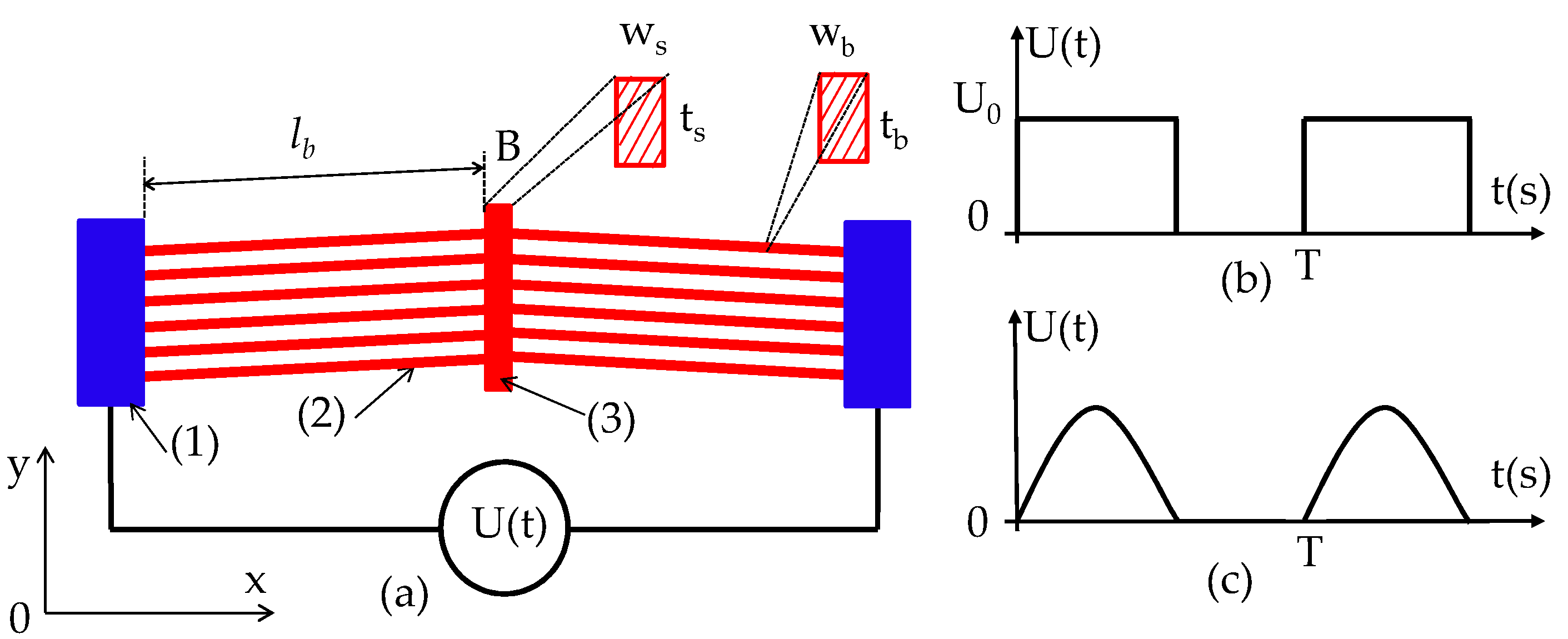
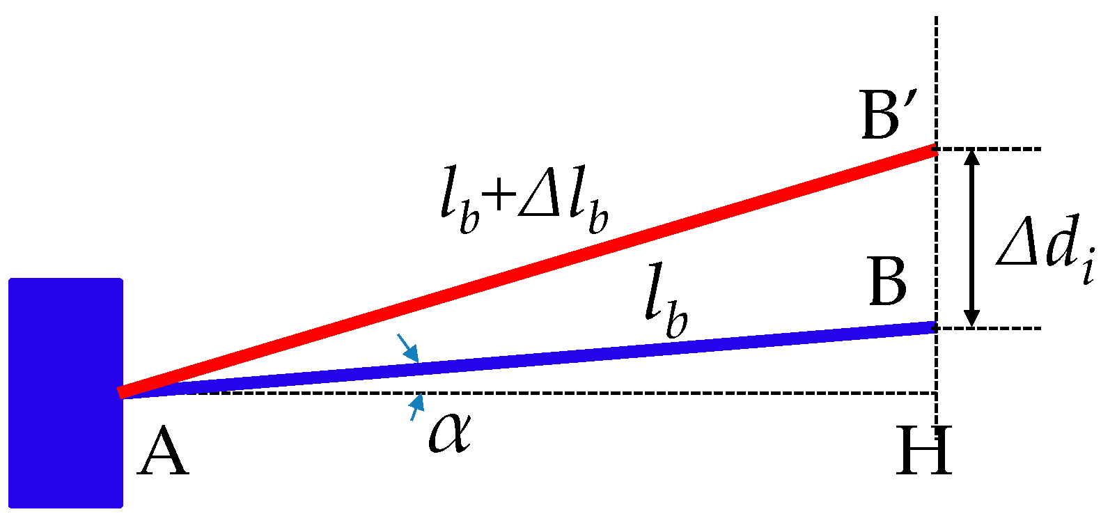
2. Configuration and Working Principle of the V-Shaped Electrothermal Microactuator

Although the application of the ILC controller does not require any precise mathematical model of its controlled plan, a necessary so-called priori-information about its dynamic is compulsory, such as whether the controlled plan is stable or not [21,22,28,29,30,31,32]. Therefore, the verifying of VEM stability before applying the ILC approach is a prerequisite. For this purpose, especially in a virtually real environment, the paper will use a Simscape tool, since this tool allows us to create models of physical component systems based on physical connections that directly integrate with block diagrams and other modeling paradigms [33].
Around VEM, the Simscape tool is used to build a model for it based on the separation of thin beams into numerous electro–thermal elements linked together. Therefore, it is necessary to describe the physical characterization of the object.
The typical structure of the V-shaped actuator is shown in Figure 1a. It consists of n beam pairs (2) arrayed as a “V” letter with a slope angle of α in the x-direction. They are connected to two fixed electrodes (called bond pads-1). The shuttle (3) is at the center and suspended by the V-shaped beam system.
The power supply for the system is in the form of a square or half cycle of sine waves. In the driving period (i.e., first half of the cycle), the voltage is applied to the fixed electrodes (1), the current transmits through the beam system (2), and then it produces heat. The beams will be heated and expand along the beams length l b , hence generating a displacement of the shuttle (3) in the y-direction.
In the returning period, the voltage goes to zero and the temperature of the beams decreases gradually. They will shrink and pull the shuttle (3) until it returns to the initial position. The geometric parameters of Figure 1a are given in Table 1.
Displacement of the beam tip, B, (called Δ d i ) can be shown as a scheme in Figure 2.
The vertical displacement (i.e., in the y-direction) of the single beam can be calculated as:
Δ d i = ( l b + Δ l b ) 2 ( l b cos α ) 2 l b sin α
The displacement of the actuator system Δ d equals the vertical displacement of a single beam plus a half of the expansion of the shuttle 1 2 Δ l s (assuming that the shuttle expands on both tips B). We have:
Δ d = ( l b + Δ l b ) 2 ( l b cos α ) 2 l b sin α + 1 2 Δ l s

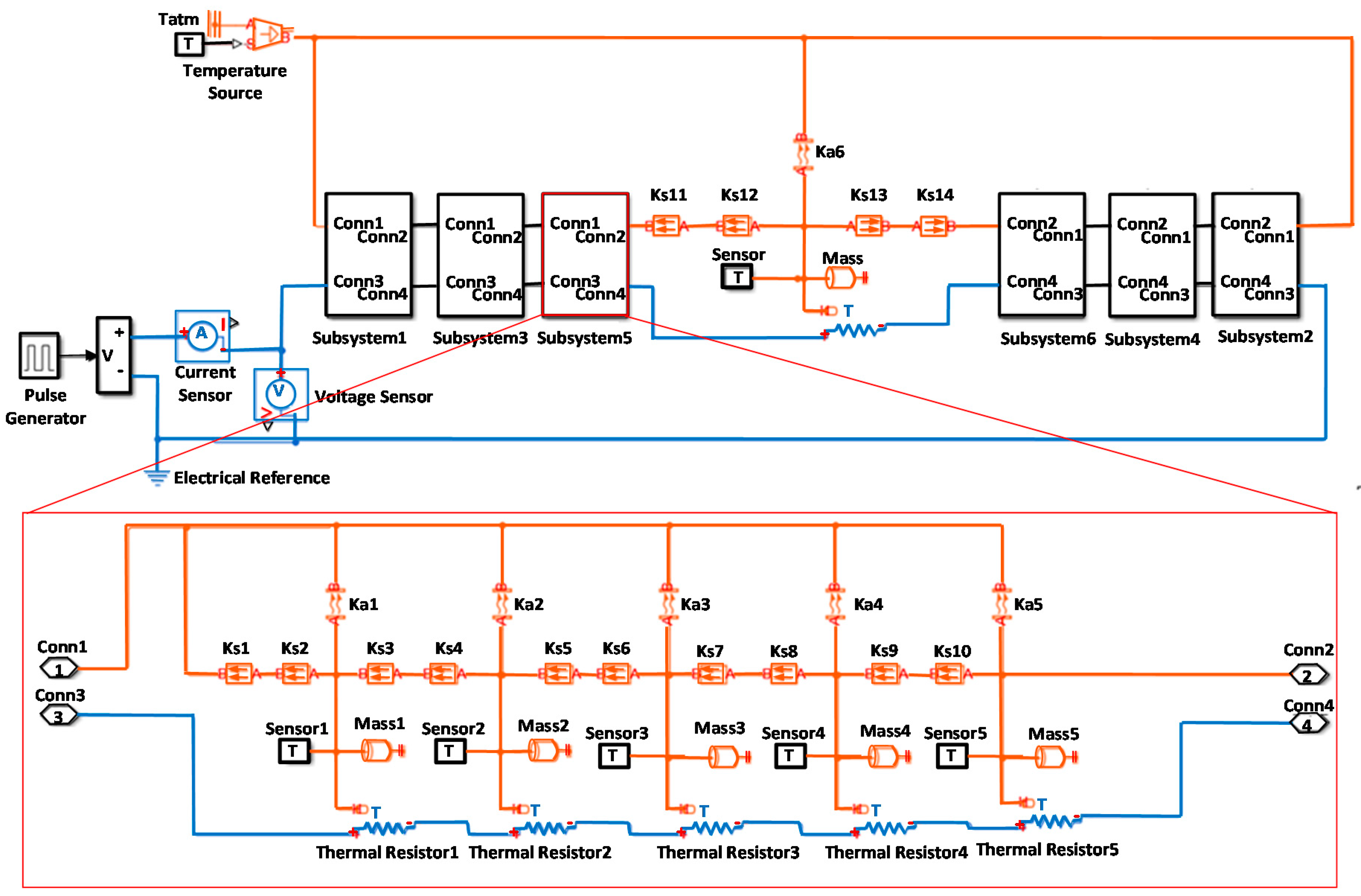
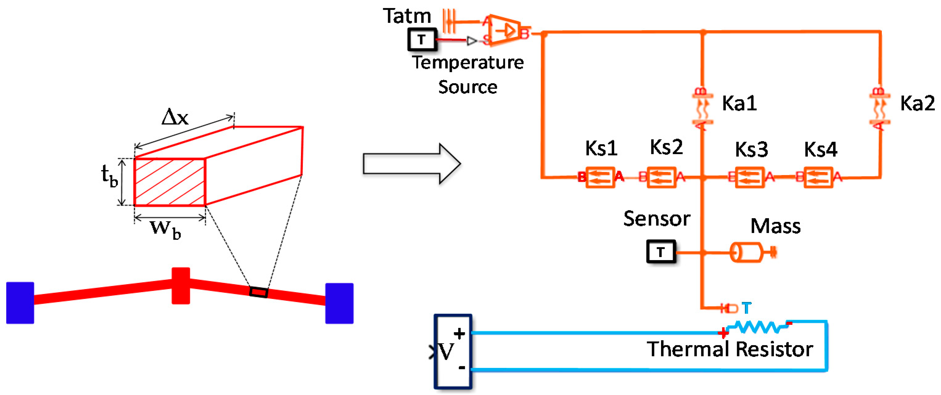
3. Simscape Model of V-Shaped Beam System

As mentioned before, Simscape is a multi-field simulation tool (electricity, magnetism, thermal, mechanical, hydraulic, pneumatic, other physical fields, etc.) in Simulink. It helps users to build object models relying on the built-in physical models. Hence, this tool allows us to create a multi-field transformation model of physical signals on the same interface as designing and real systems, without using the mathematical model of the controlled objects [33].
Moreover, Simscape helps to develop control systems and check the input–output operation of the system. Based on the working principle, it can be illustrated by the physical process of converting energy in the V-shaped beam in a series of electric–thermal-mechanics. In this case, we use a thermal resistor to describe the electric–thermal conversion process, conductive/convective heat transfer elements to describe the heat transfer process in the beam (Ks1, Ks2…), and the process of heat convection to the air (Ka1, Ka2…), respectively. Hence, with the Simscape tool, it is possible to analyze VEM system performance effectively without having to use any strictly mathematical model of it.
By using the Simscape tool for modeling VEM in a virtually real environment, a single beam is separated into tiny elements along the beam length, with the assumption that each is uniform and their temperature distributions are the same. Thus, we can model each differential element of the V-shaped beam as shown in Figure 3.
Accuracy of the model strongly depends on the number of segments and length Δ x . However, the large segment-number will cause a longer simulation time. In this work, corresponding to the fixed length, l b = 320 µm, of a single beam, each beam will be approximately separated into 15 elements, with the length of one segment Δ x = 21.3 µm, as illustrated in Figure 4.
The geometric parameters of the VEM and the material properties of silicon are given in Table 1 and Table 2.
The model of this actuator has been simulated with a square signal (amplitude: U 0 = 20 V). A temperature response of the system is exhibited in Figure 5. It represents relatively from this simulation result that VEM is a bounded input-bounded output stable object (BIBO), which met completely with the conclusions given in [8,9,11,13], as well as with our previous work presented in [9]. Hence, the ILC approach now can be applied confidently to tracking control VEM.
Furthermore, simulation results show that the output response matches closely to the physical calculation. Here, the highest temperature (Tmax) is concentrated in the shuttle and is about 425 °C, and the average temperature (Tave.) at the center of the single beam is 256 °C. A simulation by Simscape is also performed with different input signals, such as DC or half-of-sine voltage at various values of driving voltage. The obtained results match well with analysis and simulation done by ANSYS.

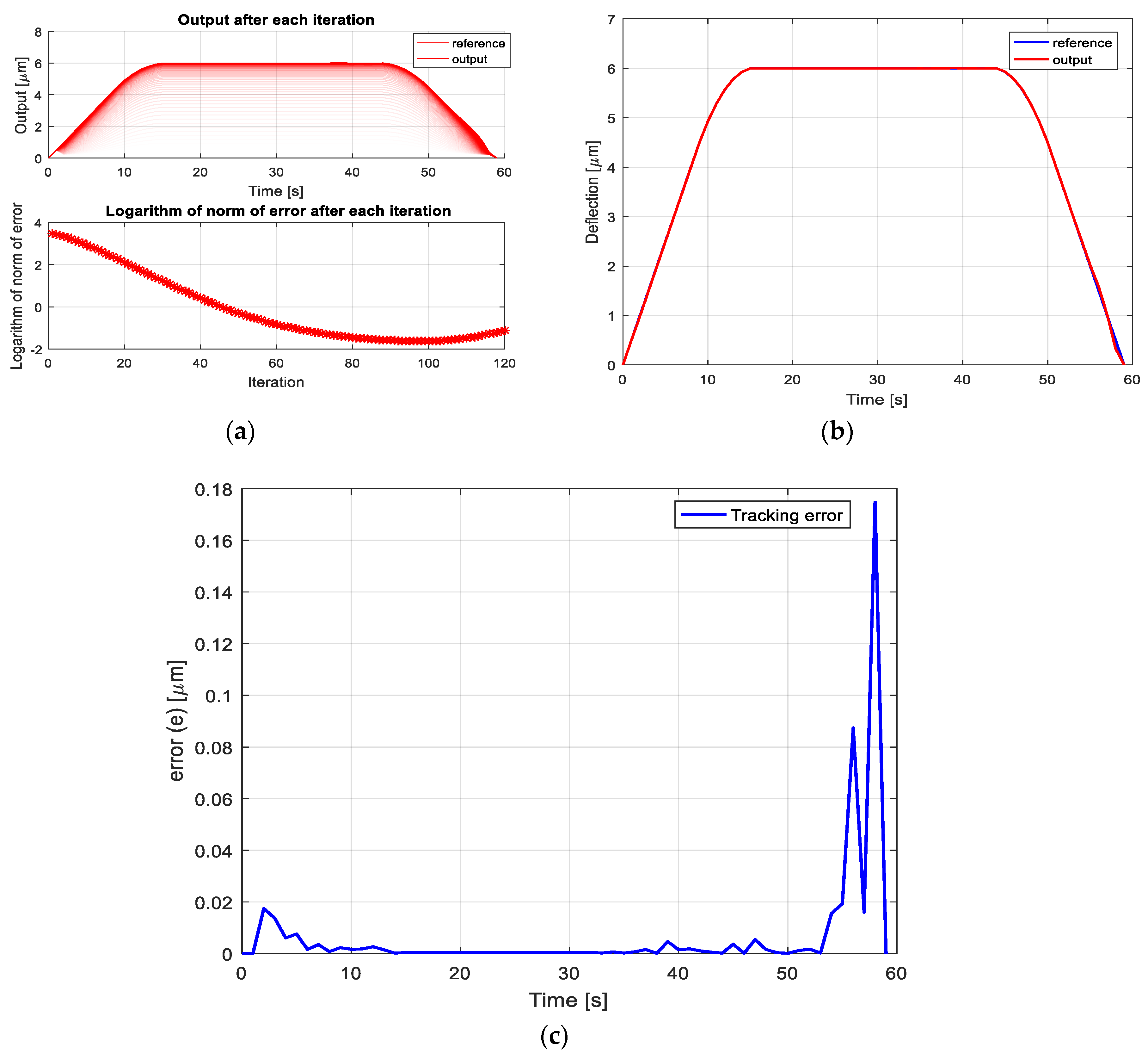
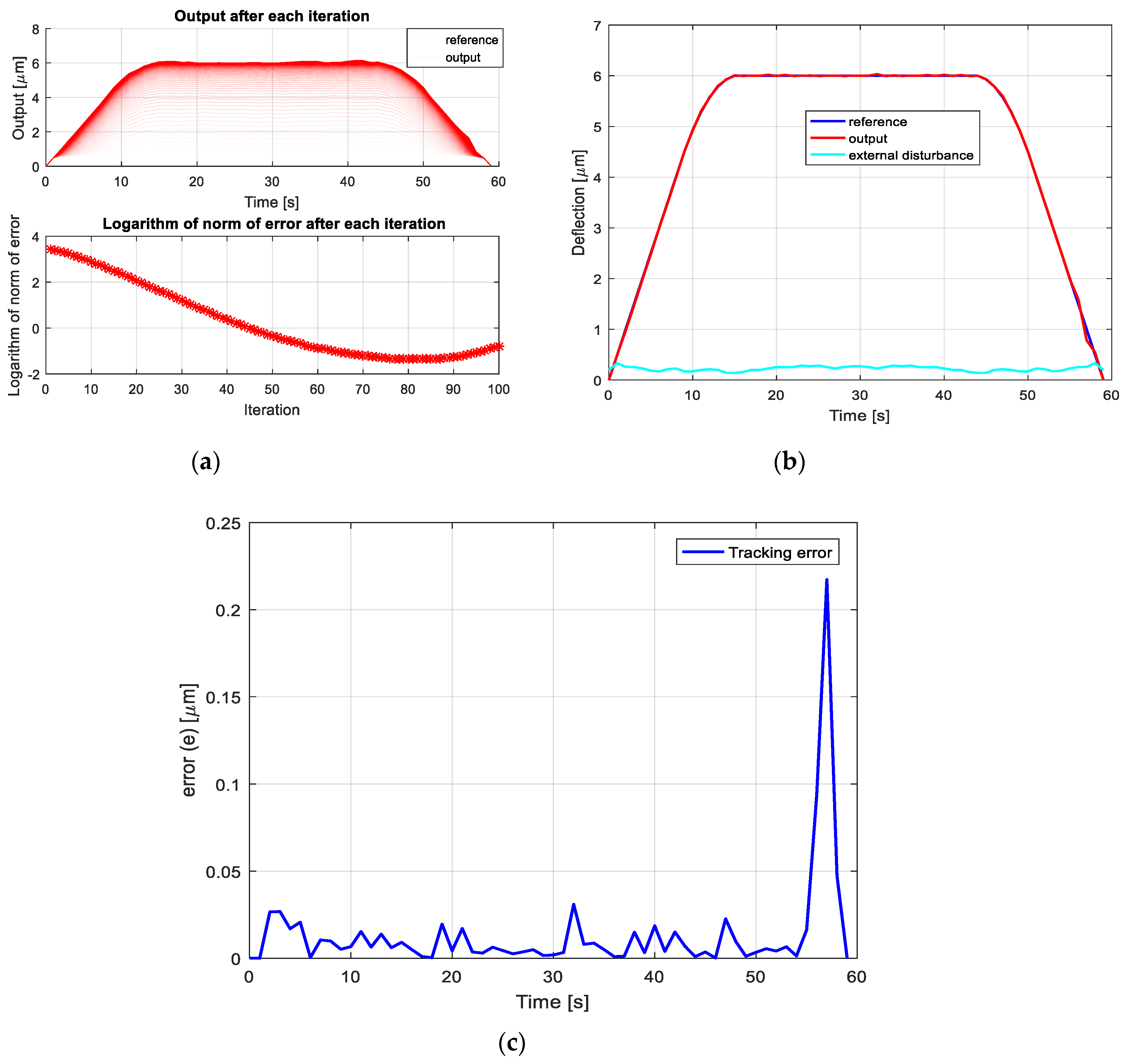
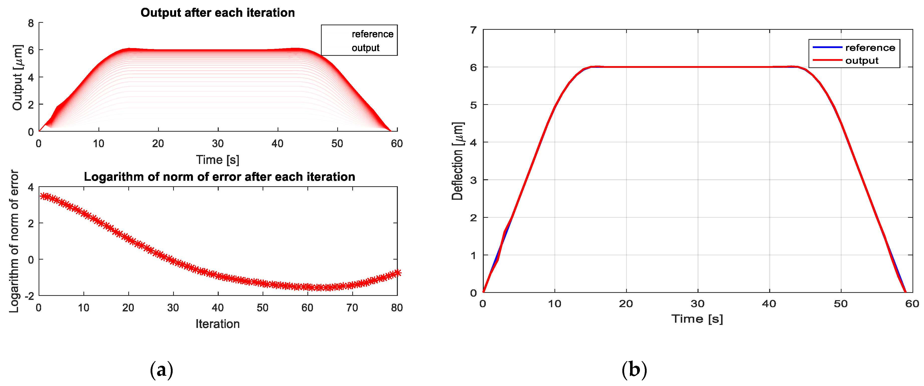
4. Iterative Learning Controller Design for VEM, Simulations and Discussion
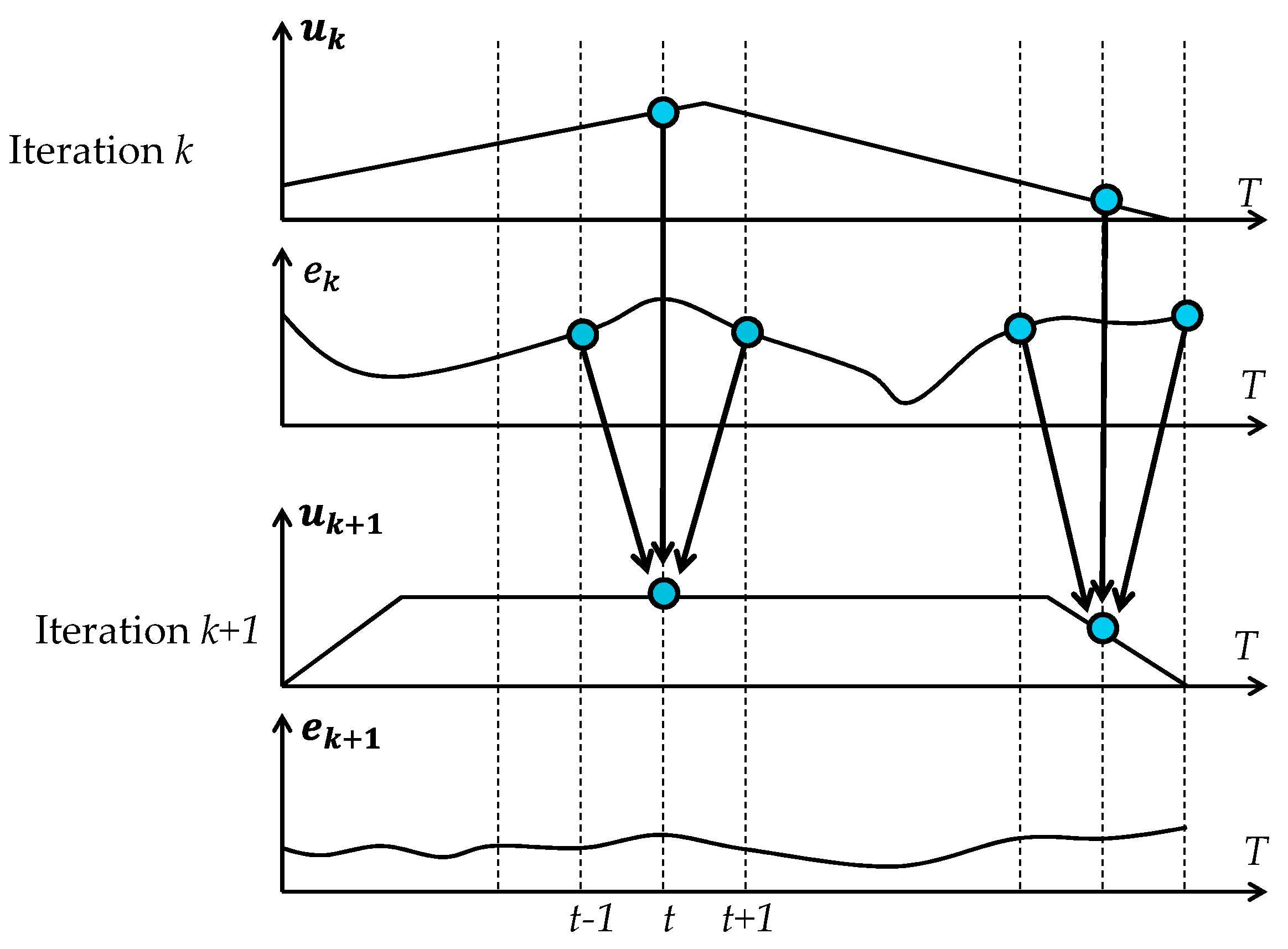
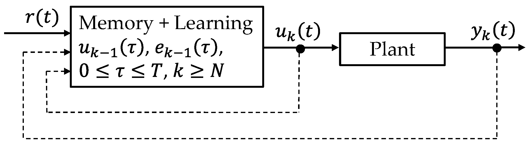
The block diagram and the working principles of iterative learning controllers are shown in Figure 6 and Figure 7 below.
The main purpose of the ILC scheme is to determine a learning function (also called the ILC algorithm [31,32]):
u k + 1 ( t ) = L ( u k ( τ 1 ) , e k ( τ 2 ) , t )
for controlled systems, denoted by P : u ( t ) y ( t ) , which work in a repetitive manner during a finite time interval: 0 t T , so that the following condition of output tracking performance:
e k ( t ) < ε
with any constant ε > 0 and any suitably defined norm, will be satisfied after a finite trial number k > K , where the subscript k indicates the trial number by learning, and
e k ( t ) = r ( t ) y k ( t )
is the tracking error belonging to the k t h trial. r ( t ) is the desired reference for the controlled system P : u ( t ) y ( t ) . Since the VEM is a controlled system that is not only stable (Figure 5), but also operates in a repetitive mode, the ILC algorithm (3) can be applied therefore directly to output tracking that controls it.
The operation of the ILC algorithm (3) above could be shortly explained as follows [28,32]:
  • First, during the k t h trial, the whole input u k ( t ) , with 0 ≤ tT is sent to the controlled plant for producing its complete response y k ( t ) .
  • Afterward, at the moment when the current trial is finished, the output tracking error (5) is calculated based on a particularly chosen learning algorithm to determining the input u k ( t ) ,   t [ 0 , T ] for the next ( k + 1 ) t h trial, which should produce a smaller tracking error than the previous input u k ( t ) . In other words, a suitably chosen learning function (3) is that, which should generate continuously:
    e k + 1 ( t ) < e k ( t )
    for k = 0 , 1 For a particular circumstance, that the input–output operator P : u ( t ) y ( t ) :
    y ( t ) = f P ( u ( t ) )
    as well as the chosen learning function (3) of an additional structure:
    u k + 1 ( t ) = u k ( t ) + f L ( e k ( t ) )
    are linear, then the requirement (6) will be satisfied, if the following sufficient condition:
    e k + 1 = r y k + 1 = r f p ( u k + 1 ) = r f p ( u k ) f p f L ( e k ) = e k f p f L ( e k ) = ( 1 p f p f L ) ( e k ) < e k
    Or   1 p f p f L < 1
    where 1 p denotes the identity operator.
Moreover, it is remarkably here for the requirement (6) that in all trials, the same initial values have to be assigned to the controlled system P : u ( t ) y ( t ) .
3.
Finally, the learning process will be continued repetitively for k = 0 , 1 , until the condition (4) is satisfied.
A meaningful version of ILC algorithms (3), which can be also applied during the whole time without having to check the required terminative condition (4) is the following uninterrupted one:
u k + 1 ( t ) = u k ( t ) + f L ( e k ( τ ) )
where 0 t T and f L ( e k ( τ ) ) = 0 if τ [ 0 , T ] . In contrast to the common context of ILC algorithm (3), this uninterrupted learning algorithm allows the learning process to be faster and be continued forever without any degradation.
Now, it is time for coming back to the design of the ILC algorithm as seen in Equations (3) or (11) for VEM. Since Uchiyama proposed his concept of iterative control for the first time in [20] based on the ILC learning algorithm in Equation (3), the ILC principle was afterwards developed very rapidly with a huge number of ILC algorithms having been published. Many of them can be found in [21,22,29,30,31,32,33]. A good summary of ILC development is presented in [34,35,36,37], in which a few of the following practicably powerful linear ILC algorithms of the alternative structure of Equation (11) are given (see [21,22] for more examples):
u k + 1 ( t ) = u k ( t ) + K e k ( t )
or [29,33]:
u k + 1 ( t ) = u k ( t ) + K e k ( i ) ( t )
and
u k + 1 ( t ) = u k ( t ) + K 1 e k ( t ) + K 2 e ˙ k ( t )
which are often known as the Derivative (D-type) and Proportional Derivative (PD-type) algorithms.
One of the most general linear ILC algorithms (11) is the one in [21] which introduced the PID-type algorithm as follows:
u k + 1 ( t ) = u k ( t ) + K 1 e k ( t ) + K 2 0 t e k ( τ ) d τ + K 3 e ˙ k ( t )
Of course, all learning parameters K , K 1 , K 2 , and K 3 of the ILC algorithms above have to be determined accordingly to the required condition (4).
The quality of the controller depends on the learning formula, controller coefficients, and number of learning iterations. In this paper, PD-type (14) and PID-type algorithm (15) will be applied to design the iterative learning controller for output tracking control of the VEM.
In this subject, the discrete time version of PD-type (14) and of PID-type (15) will be used to design ILC controllers for continuous-time VEM. It means that the following learning function:
u k + 1 ( t ) = u k ( t ) + K 1 e k ( t ) + K 2 e k ( t + 1 )
with K 1 = 0.08 and K 2 = 0.1 will be applied. These learning parameters are chosen based on a sufficiently convergent condition for the learning process presented in [28,29,35,37], under a theoretical assumption that the VEM mathematical model given in [9] is exact.
The simulation results for the displacement of the top of the beam by using the discrete time PD-type learning procedure (16) are given in Figure 8 and Figure 9 for both cases without and with an additional output disturbance. It is exhibited extraordinary here in the obtained results, especially in Figure 8a (without external disturbances) and Figure 9a (with an additional output disturbance), which illustrate the dependence of maximal tracking error on applied learning step number, that the tracking error does not decrease monotonously if the learning number is increased, as proven in [28,29,30,31,32,33,34,35,36,37] by using a mathematical model of VEM. A reason for it could be that an uncertain difference between the mathematical models given in [5,8,9] and the here used Simscape model of VEM has appeared. It can be deduced that these mathematical models may not be precise enough for using it to design a conventional open-loop controller for VEM.
Next, Figure 10 and Figure 11 illustrate the simulation results by using the following discrete time PID learning algorithm:
u k + 1 ( t ) = u k ( t ) + K 1 e k ( t ) + K 2 e k ( t 1 ) + K 3 e k ( t + 1 )
with the chosen learning parameters K 1 = 0.08 and K 2 = K 3 = 0.1 for the two cases without and with output disturbances, respectively. These learning parameters are also chosen correspondingly to the required convergent condition presented in [28,29,35,37] and the mathematical model of VEM given in [9]. Likely by using the PD-type, as exhibited in Figure 10a and Figure 11a for both cases without and with an additional disturbance in system output, respectively, the tracking error does not decrease monotonously by increasing the learning steps as usual. It implies, therefore here also, that the mathematical model presented in [9] may not be precise enough for using it to design a conventional open-loop controller for VEM.
Figure 8c, Figure 9c, Figure 10c, and Figure 11c illustrate the output tracking error. These simulation results confirm that the designed ILC controllers (16) and (17) have met the tracking performance as expected.
Figure 8c, Figure 9c, Figure 10c, and Figure 11c exhibit output tracking errors for a better view of system tracking performance again, where in Figure 9c and Figure 11c are the results in the case of output disturbed VEM and in Figure 8c and Figure 10c are results on the contrary case.
The obtained simulation results in Figure 8b, Figure 9b, Figure 10b, and Figure 11b show that the chosen learning function and their coefficients have produced the output that converges gradually to the desired reference with a minimal tracking error after a finite number of learning steps. Concretely, for a given trapezoidal reference, the output of the system is almost identical to the reference after 100 iterations with the minimal tracking norm = 0.1994 (Euclidean norm) by using the PD learning function (16) and after 62 iterations to reach the minimal tracking norm = 0.1811 with the PID learning function (17). When an external disturbance occurs additionally in the system, then an amplitude of about 10% compared to the amplitude of the set value is added. The output is relatively close to the desired result after 85 iterations with a minimal tracking norm of 0.2296 by using the PD learning function (16), and after 54 iterations to the minimal norm of 0.2138 with the PID learning function (17).
Both learning algorithms (16) and (17) produce a good disturbance resistance. If the disturbance is predetermined, the results will converge faster. Figure 8, Figure 9, Figure 10 and Figure 11 show that the PID learning algorithm (17) produces a relatively faster convergent rate than the PD learning algorithm (16). Additionally, if we reduce the coefficients K 1 , K 2 , and K 3 , the learning process may be longer, but the error will be smaller.
After all, the simulation also shows that the Simscape model reflects the physical characterization of VEM more precisely than its mathematical model presented in [9]. The control behavior obtained by simulating with Simscape model of VEM becomes, therefore, more accurate.

5. Conclusions

The paper proposes two types of discrete time iterative learning controllers to control the displacement of the continuous-time V-shaped electrothermal microactuator (VEM): the PD-type and the PID-type. To verify the output tracking performance of these so called “sampled data control systems” in a virtually real environment, the Simscape tool has been used for modeling the thermal transmission/emission in a V-shaped beam via separating a single beam into segments along the beam length. Hence, every segment could then be considered to be identical in both electrical and thermal properties. By using this model, the dynamic system behavior will be simulated nearly as in a real actuator system, which is to be controlled. Therefore, we can be confident that the introduced controller will act fast in the same way as in the real environment.
The obtained simulation results for both cases, without and with an external disturbance, showed that the designed controller is robust with disturbances, completely suitable for heat transfer in a thin beam of VEM, and met the required system performance as expected. Moreover, it helped the system to be more stable, faster in calculation, and produce a smaller tracking error.
Finally, it can be seen here that the introduced control method based on a modified PD-type and PID-type iterative learning could also be applied easily for controlling different MEMS devices such as hydraulic, pneumatic, or other physical models.

Author Contributions

N.D.P. contributed to the control idea; N.T.D. participated with the control algorithm implementation, analysis of the simulation results, and paper setting; P.H.P. and N.Q.D. helped with the verification of the obtained system performance by discussing and paper correction.

Funding

This research is funded by the Vietnam National Foundation for Science and Technology Development (NAFOSTED) under Grant number ‘‘107.01-2019.05”.

Conflicts of Interest

The authors declare no conflict of interest.

References

  1. Sinclair, M.J. A high force low area MEMS thermal actuator. In Proceedings of the ITHERM 2000, the Seventh Intersociety Conference on Thermal and Thermomechanical Phenomena in Electronic Systems (Cat. No. 00CH37069), Las Vegas, NV, USA, 23–26 May 2000; pp. 127–132. [Google Scholar]
  2. Mayyas, M.; Stephanou, H. Electrothermoelastic modeling of MEMS gripper. Microsyst. Technol. 2009, 15, 637–646. [Google Scholar] [CrossRef]
  3. Maloney, J.M.; Schreiber, D.S.; Devoe, D.L. Large-force electrothermal linear micromotors. J. Micromech. Microeng. 2003, 14, 226–234. [Google Scholar] [CrossRef]
  4. Li, X.; Zhao, Y.; Hu, T.; Xu, W.; Zhao, Y.; Bai, Y.; Ren, W. Design of a large displacement thermal actuator with a cascaded V-beam amplification for MEMS safety-and-arming devices. Microsyst. Technol. 2015, 21, 2367–2374. [Google Scholar] [CrossRef]
  5. Shen, X.; Chen, X. Mechanical performance of a cascaded V-shaped electrothermal actuator. Int. J. Adv. Robot. Syst. 2013, 10, 379. [Google Scholar] [CrossRef]
  6. Park, J.S.; Chu, L.L.; Oliver, A.D.; Gianchandani, Y.B. Bent-beam electrothermal actuators-Part II: Linear and rotary microengines. J. Microelectromech. Syst. 2001, 10, 255–262. [Google Scholar] [CrossRef]
  7. Messenger, R.K. Modeling and Control of Surface Micromachined Thermal Actuators. Master Thesis, Brigham Young University, Provo, UT, USA, 21 May 2004. [Google Scholar]
  8. Zhang, Z.; Yu, Y.; Liu, X.; Zhang, X. Dynamic modelling and analysis of V-and Z-shaped electrothermal microactuators. Microsyst. Technol. 2017, 23, 3775–3789. [Google Scholar] [CrossRef]
  9. Dzung, N.T.; Nam, D.P.; Dich, N.Q. Modelling and Control Design of a V-shaped Thermal Actuator System via Partial Derivative Equation Approach. In Proceedings of the ICMRE 2019, Rome, Italy, 16–19 February 2019; pp. 78–82. [Google Scholar]
  10. Ferreira, A.; Aphale, S.S. A survey of modeling and control techniques for micro-and nanoelectromechanical systems. IEEE Trans. Syst. Man Cybern. Part C Appl. Rev. 2010, 41, 350–364. [Google Scholar] [CrossRef]
  11. Velázquez, R.; Pissaloux, E.E. Modelling and temperature control of shape memory alloys with fast electrical heating. Int. J. Mech. Control 2012, 13, 1–8. [Google Scholar]
  12. Walraven, J.A.; Baker, M.S.; Headley, T.J.; Plass, R.A. Compliant Thermo-Mechanical MEMS Actuators; Final Report; Sandia National Laboratories: Albuquerque, NM, USA, 2004.
  13. Zhu, Y.; Bazaei, A.; Moheimani, S.R.; Yuce, M.R. Design, modeling, and control of a micromachined nanopositioner with integrated electrothermal actuation and sensing. J. Microelectromech. Syst. 2011, 20, 711–719. [Google Scholar] [CrossRef]
  14. Yang, P.; Mechefske, C.; Lai, Y. Micro thermal actuator with integrated capacitive position sensor. In Proceedings of the 2009 2nd Microsystems and Nanoelectronics Research Conference, Ottawa, ON, Canada, 13–14 October 2009; pp. 25–28. [Google Scholar]
  15. Vagia, M.; Nikolakopoulos, G.; Tzes, A. Intelligent robust controller design for a micro-actuator. J. Intell. Robot. Syst. 2006, 47, 299–315. [Google Scholar] [CrossRef]
  16. Enikov, E.T.; Kedar, S.S.; Lazarov, K.V. Analytical model for analysis and design of V-shaped thermal microactuators. J. Microelectromech. Syst. 2005, 14, 788–798. [Google Scholar] [CrossRef]
  17. Ma, F.; Chen, G. Modeling V-shape Thermal In-plane Microactuator using Chained Beam-Constraint-Model. In Proceedings of the 2014 International Conference on Manipulation, Manufacturing and Measurement on the Nanoscale (3M-NANO), Taipei, Taiwan, 27–31 October 2014; pp. 244–248. [Google Scholar]
  18. Jamshidi, M.; Zilouchian, A. Intelligent Control Systems Using Soft Computing Methodologies; CRC Press: Boca Raton, FL, USA, 2001. [Google Scholar]
  19. Antsaklis, P.J. Intelligent control. In wiley Encyclopedia of Electrical and Electronics Engineering; Webster, J., Ed.; John Wiley & Sons, Inc.: Torino, Italy, 1999; pp. 493–503. [Google Scholar]
  20. Uchiyama, M. Formation of high-speed motion pattern of a mechanical arm by trial. Trans. Soc. Instrum. Control Eng. 1978, 14, 706–712. [Google Scholar] [CrossRef]
  21. Chen, C.-K.; Li, K.-S. Iterative learning control for robotic contouring. In Proceedings of the 2009 IEEE International Conference on Control and Automation, Christchurch, New Zealand, 9–11 December 2009. [Google Scholar]
  22. Arimoto, S.; Kawamura, S.; Miyazaki, F. Bettering operation of robots by learning. J. Robot. Syst. 1984, 1, 123–140. [Google Scholar] [CrossRef]
  23. Kim, D.; Kim, S. An iterative learning control method with application for CNC machine tools. IEEE Trans. Ind. Appl. 1996, 32, 66–72. [Google Scholar]
  24. de Roover, D.; Bosgra, O.H. Synthesis of robust multivariable iterative learning controllers with application to a wafer stage motion system. Int. J. Control 2000, 73, 968–979. [Google Scholar] [CrossRef]
  25. Havlicsek, H.; Alleyne, A. Nonlinear control of an electrohydraulic injection molding machine via iterative adaptive learning. IEEE/ASME Trans. Mechatron. 1999, 4, 312–323. [Google Scholar] [CrossRef]
  26. Barton, A.D.; Lewin, P.L.; Brown, D.J. Practical implementation of a real-time iterative learning position controller. Int. J. Control 2000, 73, 992–999. [Google Scholar] [CrossRef]
  27. Yang, D.R.; Lee, K.S.; Ahn, H.J.; Lee, J.H. Experimental application of a quadratic optimal iterative learning control method for control of wafer temperature uniformity in rapid thermal processing. IEEE Trans. Semicond. Manuf. 2003, 16, 36–44. [Google Scholar] [CrossRef]
  28. Moore, K.L. Iterative Learning Control for Deterministic Systems; Springer Science & Business Media: Berlin, Germany, 2012. [Google Scholar]
  29. Xu, J.-X.; Tan, Y. Linear and Nonlinear Iterative Learning Control; Springer: Berlin, Germany, 2003. [Google Scholar]
  30. Norrlöf, M. Iterative Learning Control-Analysis, Design, and Experiments; Diss, No.653; Linkoepings University: Linkoepings, Sweden, 2000. [Google Scholar]
  31. Moore, K.L.; Dahleh, M.; Bhattacharyya, S.P. Iterative learning for trajectory control. In Proceedings of the 28th IEEE Conference on Decision and Control, Tampa, FL, USA, 13–15 December 1989; pp. 860–865. [Google Scholar]
  32. Vita, V.; Vitas, A.; Chatzarakis, G.E. Design, implementation and evaluation of an optimal iterative learning control algorithm. Wseas Trans. Circuits Syst. 2011, 10, 39–48. [Google Scholar]
  33. Getting Started with Simscape. MathLab Tutorials. R2019b. Available online: https://ch.mathworks.com/help/physmod/simscape/getting-started-with-simscape.html (accessed on 15 October 2019).
  34. Tian, S.; Liu, Q.; Dai, X.; Zhang, J. A PD-type iterative learning control algorithm for singular discrete systems. Adv. Differ. Equ. 2016, 2016, 321. [Google Scholar] [CrossRef]
  35. Owens, D.H.; Amann, N.; Rogers, E. Iterative learning control-an overview of recent algorithms. Appl. Math. Comput. Sci. 1995, 5, 425–438. [Google Scholar]
  36. Owens, D.H.; Hätönen, J. Iterative learning control-The state of the art. IFAC Proc. Vol. 2004, 37, 51–62. [Google Scholar] [CrossRef]
  37. Tharayil, D.A.B.M.; Alleyne, A.G. A survey of iterative learning control: A learning-based method for high performance tracking control. IEEE Control Syst. Mag. 2006, 26, 96–114. [Google Scholar]
Figure 1. (a) Structure and working principle of the V-shaped actuator system; (b) and (c) are the functional signals.
Electronics 08 01410 g001
Figure 2. Displacement of the tip of the beam.
Electronics 08 01410 g002
Figure 3. Modeling electric–thermal of one segment, ∆x, in Simscape tool.
Electronics 08 01410 g003
Figure 4. Modeling electric–thermal elements of V-shaped beam.
Electronics 08 01410 g004
Figure 5. Response of maximum temperature and the average temperature of the beam system with a square signal.
Electronics 08 01410 g005
Figure 6. Block diagram of iterative learning control (ILC).
Electronics 08 01410 g006
Figure 7. Working principles of ILC.
Electronics 08 01410 g007
Figure 8. (a) Tracking error in dependence of learning number (PD-type, no external disturbance). (b) Simulation results with a trapezoidal signal, no external disturbance, after 100 iterations. (c) Displacement error after 100 iterations.
Electronics 08 01410 g008
Figure 9. Tracking error in dependence of learning number (PD-type, external disturbance 10%). (b) Simulation results with a trapezoidal signal, external disturbance 10%, after 85 iterations. (c) Displacement error after 85 iterations.
Electronics 08 01410 g009
Figure 10. (a) Tracking error in dependence of learning number (PID-type, no external disturbance). (b) Simulation results with a trapezoidal signal, no external disturbance, 62 iterations. (c) Displacement error after 62 iterations.
Electronics 08 01410 g010aElectronics 08 01410 g010b
Figure 11. (a) Tracking error in dependence of learning number (PID-type, external disturbance 10%). (b) Results with a trapezoidal signal, external disturbance of 10% amplitude after 54 iterations. (c) Displacement error after 54 iterations.
Electronics 08 01410 g011
Table 1. Geometric parameters of the V-shaped actuator.
ParametersSymbolValueUnit
Length of a single beamlb320µm
Width of a single beamwb4.5µm
The thickness of beamtb30µm
The length of the shuttlels125µm
The width of the shuttlews40µm
The thickness of the shuttlets30µm
Air gapga4µm
Table 2. Material properties of silicon.
ParametersSymbolValueUnit
Specific weightD2330Kg/m3
Specific heatCp710J/Kg°C
Resistivity at room temperatureρ01200Ωmm
Thermal conductivity of siliconKs146W/m°C
Thermal conductivity of airKa0.026W/m°C

