Article

Combination of High-Order Modulation and Non-Binary LDPC Codes over GF(7) for Non-Linear Satellite Channels

School of Microelectronics, Tianjin University, Tianjin 300072, China
*
Author to whom correspondence should be addressed.
Electronics 2019, 8(12), 1396; https://doi.org/10.3390/electronics8121396
Submission received: 4 November 2019 / Revised: 18 November 2019 / Accepted: 20 November 2019 / Published: 22 November 2019
(This article belongs to the Collection Millimeter and Terahertz Wireless Communications)

Abstract

:
High-order modulations are necessary to improve the bandwidth efficiency of the satellite communication system. However, the non-linear characteristic of satellite channels limits the application of high-order modulations. In this paper, we propose a new 7-point constellation which is expected to be effectively applied to the satellite communication system, and combine it with non-binary low-density parity-check (NB-LDPC) codes over Galois field GF(7) to guarantee the reliability of the data transmission. The exact expression for the average symbol error probability (SEP) of 7-order quadrature amplitude modulation (7-QAM) over the Additive White Gaussian Noise (AWGN) channel is derived, and the non-linear distortion over satellite channels is also analyzed. Simulation results reveal that, compared with the traditional 8-order phase-shift keying (8-PSK), the 7-QAM method can achieve about 3 dB gain over the AWGN channel without channel coding at symbol error rate (SER) of 10 - 6 . Moreover, the proposed combined coded modulation scheme also has better SER performance than the NB-LDPC coded 8-PSK modulation scheme over the non-linear satellite channel.

1. Introduction

High-order modulations are important to improve the data rate and spectral efficiency of satellite communication systems [1]. However, the non-linear distortion due to the non-linear transfer characteristic of the high power amplifier (HPA) would reduce the overall performance gain expected with the application of higher modulation orders [2]. Therefore, the appropriate high-order constellation which is less influenced by non-linear effects is expected for high throughput satellite communications.
High-order modulations commonly used are M-ary phase-shift keying (M-PSK), M-ary quadrature amplitude modulation (M-QAM) and M-ary amplitude and phase-shift keying (M-APSK). Generally, M-PSK with constant envelope is robust against the non-linear distortion, but its anti-noise performance is worse than that of M-QAM if the modulation order is larger than four. However, high-order QAM usually has high peak-to-average power ratio (PAPR), and it is not suitable for the satellite communication system due to its high sensitivity to the non-linear distortion [3,4]. APSK has good performance in both anti-noise and robustness to non-linear distortion when the modulation order is greater than eight, and proper constellations suitable for the satellite communication system could be achieved through the optimization design [5,6,7,8]. The second generation digital video broadcasting over satellite (DVB-S2) standard recommends 8-PSK, 16-APSK, and 32-APSK [9,10]. Moreover, the scheme of combining the high-order modulation with error correction codes could guarantee the reliability of data transmissions and has been widely applied to the satellite communication system. In addition, the combination of 8-PSK and low-density parity-check (LDPC) codes is a very popular candidate scheme for satellite communication system because of the robustness of 8-PSK against the non-linear distortion and the excellent error correction performance of the LDPC codes [11]. However, compared to other constellations, such as 8-QAM, 5-QAM, and 9-QAM presented in [12,13] and the general hexagonal constellation [14,15], 8-PSK only has a ring and wastes the space of little amplitude, which results in the poor anti-noise performance and the limitation for the error performance of this scheme. In [16], 5-QAM is used as the modulation method in the solution for the fifth-generation (5G) cellular networks.
For a better trade-off between the power efficiency and modulation order, we propose a new 7-point constellation based on the hexagonal grid signal sets which is optimum in the two-dimensional (I-Q) space [14,15,17]. The new 7-QAM constellation is also with a point in the original point as 5-QAM and 9-QAM, and it is expected to achieve better error performance over the non-linear satellite channel than the conventional 8-PSK and 8-QAM because of its excellent natures of both PAPR and minimum Euclidean distance [18,19,20], which means that it has better anti-noise performance and simultaneously is less influenced by the non-linear effects. Moreover, for the reliability of data transmission, the new 7-QAM constellation is combined with non-binary LDPC (NB-LDPC) codes over GF(7) because its modulation order is not the power of 2 and does not match the binary codes. In addition, the NB-LDPC codes, often with better error correction performance than binary LDPC codes [21], could be better adapted to high-order modulations without considering the inter-conversion between bit probability and symbol probability. These advantages of the 7-QAM constellation are verified through the calculating of PAPR, the derivation of an exact intuitive geometric infinite double series for its symbol error probability (SEP) over the Additive White Gaussian Noise (AWGN) channel using the similar derivation in [22,23,24,25,26,27,28,29,30] and the analysis of its sensitivity to the nonlinearity of HPAs. Finally, the demodulation threshold of 7-QAM and the symbol error rate (SER) performance of the proposed coded modulation scheme are simulated.
The rest of this paper is organized as follows. Section 2 presents the non-linear satellite channel model. Section 3 gives the design and analysis of 7-QAM constellation. In Section 4, we combine 7-QAM with NB-LDPC codes over GF(7). The simulation results and analyses are reported in Section 5. Section 6 finally concludes the paper.

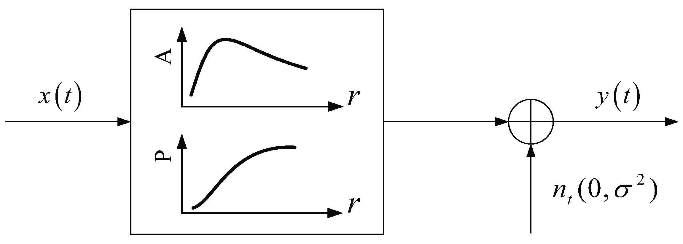
2. Nonlinear Satellite Channel Model

Due to the non-linear characteristic of the HPA, which is usually operated near the saturation because of the power limitation of the satellite, the non-linear distortion is introduced to the transmitted signals [31]. Therefore, the non-linear satellite channel model can be established according to the non-linear characteristics of HPAs.
Figure 1 shows the block diagram of the non-linear satellite channel model, which is composed of the non-linear conversion module and the AWGN module. Assume that the signals transmitted to the non-linear channel model are narrowband relative to the bandwidth of the satellite transponder and the coherent detection is perfect. Let the input signal of the non-linear channel model be
x ( t ) = r ( t ) exp ( j ϕ ( t ) ) ,
and then the output signal can be expressed as
y t = A r t exp j ϕ t + P r t + n t ,
where y ( t ) is the received signal, n ( t ) is the Gaussian white noise with mean 0 and variance σ 2 = N 0 / 2 , r ( t ) and ϕ ( t ) are the amplitude and phase of the modulated signal, respectively, A [ r ( t ) ] and P [ r ( t ) ] are the non-linear distortions in amplitude (usually called AM/AM conversion) and phase (usually called AM/PM conversion). Moreover, the AM/AM conversion and the AM/PM conversion are described using the Saleh model, as shown in Equations (3) and (4), respectively [32].
A [ r ( t ) ] = α a r ( t ) 1 + β a r ( t ) 2 ,
P [ r ( t ) ] = α p r ( t ) 2 1 + β p r ( t ) 2 ,
where α a , β a , α p , β p are parameters determined by characteristics of the HPA.

3. Design and Analysis of 7-QAM Constellation

In this section, we give the design of 7-QAM constellation. In addition, the theoretical analysis of its performance is carried out by calculating its PAPR, deriving its exact expression for the SEP over the AWGN channel and analyzing the non-linear distortion introduced to transmitted signals.

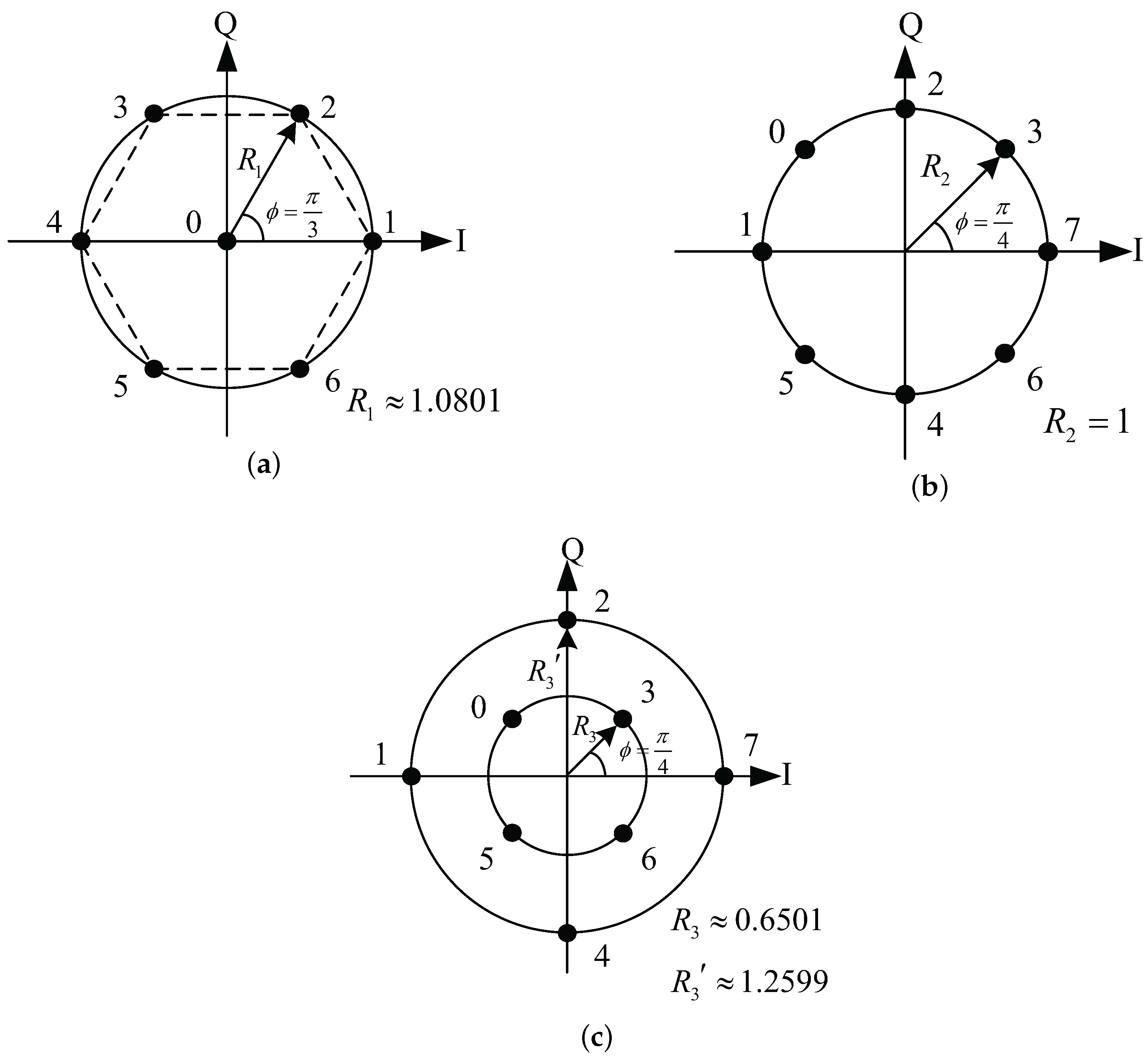
3.1. Design of 7-QAM Constellation

In order to reduce the influence of non-linear distortions on the signal points and simultaneously obtain better anti-noise performance, the new constellation is designed based on the hexagonal grid signal sets of seven signals given in [14]. In addition, the configuration of new constellation is 1 + 6. Specifically, as shown in Figure 2a, one signal point is on the origin point, and the other six signal points are evenly arranged on the outer circle with the phase difference of π / 3 . The vector expression of 7-QAM signals can be written as
x k = 0 , 0 , k = 0 , x k = R 1 cos 2 π k - 1 6 , R 1 sin 2 π k - 1 6 , 1 k 6 ,
where R 1 is the radius of the 7-QAM constellation.
The constellation diagrams of the conventional 8-PSK and 8-QAM are also demonstrated in Figure 2. The signal points are equiprobable, so that, for the normalization of power, the radiuses of these constellations are R 1 1.0801 , R 2 = 1 , R 3 0.6501 and R 3 1.2559 .
Table 1 shows the comparison for parameters of the three constellations presented in Figure 2, and the minimum phase difference θ min of 7-QAM is the value except the signal point ‘0’. It can be known from Table 1 that the minimum Euclidean distance d min of the 7-QAM constellation is 3 dB higher than that of the 8-PSK constellation and is 1.4 dB higher than that of 8-QAM constellation, which reflects the fact that the anti-noise performance of 7-QAM is much better than that of 8-PSK and 8-QAM.
More serious non-linear distortion would be introduced as applying the constellation with higher PAPR to the satellite communication system. For the practical consideration, the PAPR of 7-QAM constellation is calculated. The PAPR of the constellation can be calculated by
P A P R = E max E s ,
where E s is the average energy per symbol of the constellation and E max is the maximum energy of the modulated signal. Specifically, in the case that half of the minimum distance between adjacent symbols is d, the average energy per symbol of the 7-QAM constellation, denoted as E 7 - QAM , can be calculated as
E 7 - QAM = 1 7 k = 1 7 Re S k 2 + Im S k 2 = 1 7 6 × 2 d 2 = 24 d 2 7 ,
where S k represents the k-th signal point of the 7-QAM constellation, Re S k and Im S k mean the real and imaginary values of the signal point S k , respectively. In addition, the maximum energy of 7-QAM signal is 4 d 2 . Thereby, the PAPR of the 7-QAM constellation is 1.1667 . With the same method, the PAPRs of the 8-PSK and 8-QAM constellations are also calculated for comparison, and the calculation results are presented in Table 2.
It can be known that the PAPR of 7-QAM constellation is 1.31 dB lower than that of 8-QAM constellation, and is 0.67 dB higher than that of 8-PSK constellation.

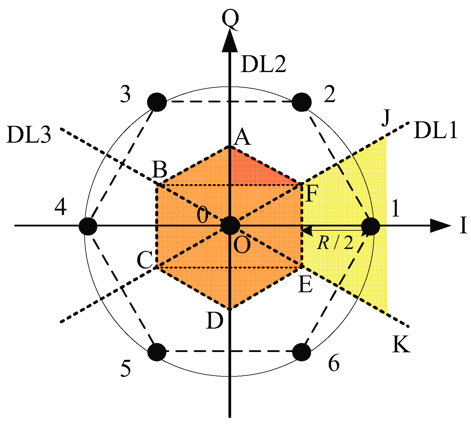
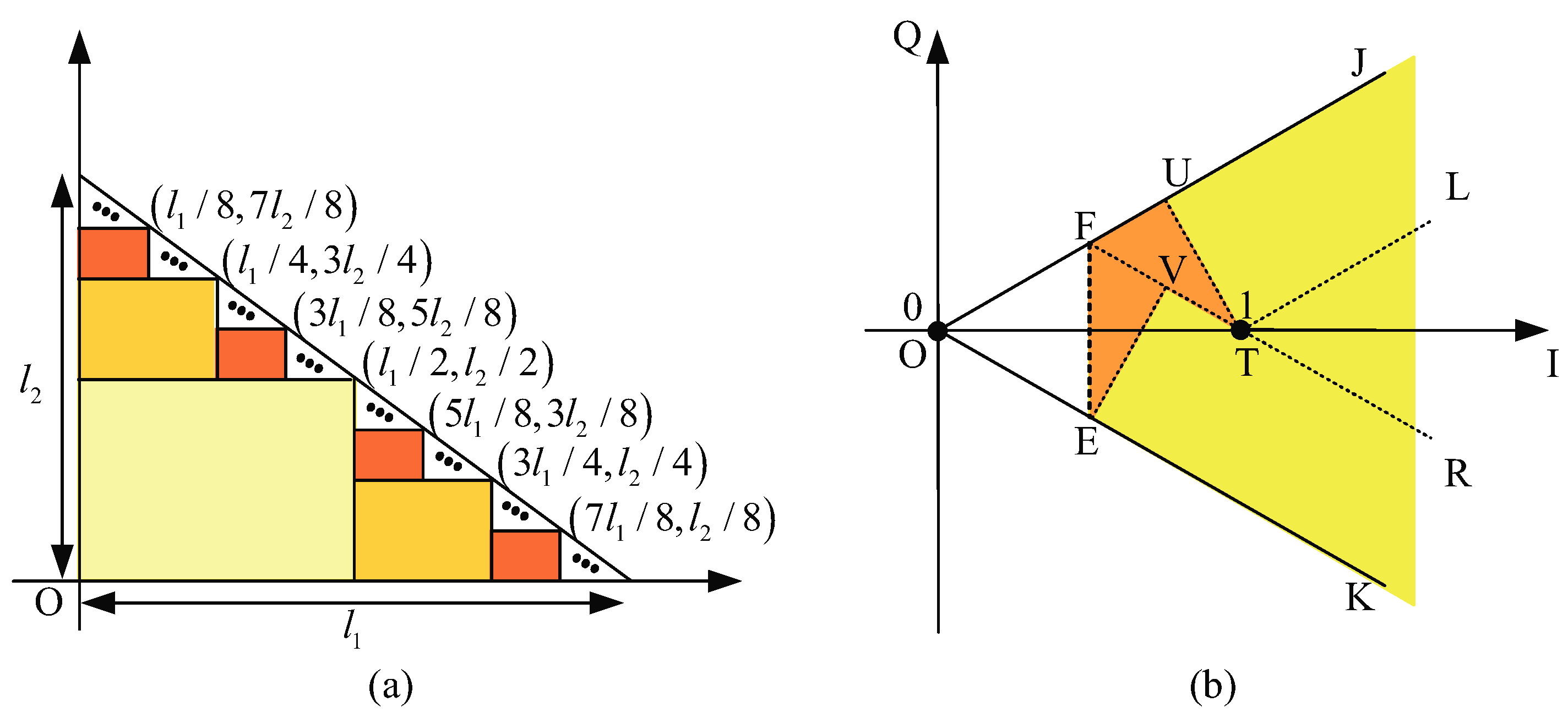
3.2. SEP Expression of 7-QAM Constellation

The formula for calculating the SEP of a constellation helps to analyze its anti-noise performance. In this part, we derive the exact closed-form expression for the SEP of the new constellation over the AWGN channel for further theoretical analysis to its error performance.
The decision region for each signal point of the 7-QAM constellation is shown in Figure 3, and DL1, DL2 (Q axis), and DL3 are decision boundaries. Obviously, according to the decision region, the signal points could be divided into two classes, interior point and points on the outer circle.
As shown in Figure 3, the correct decision region for signal point ‘0’ is the regular hexagon (ABCDEF). It is decomposed into five regions, which can be expressed as (ABW) + (AFW) + (BCEF) + (DCS) + (DES). In addition, the probabilities of correct decision for the four right triangle (RT) regions are equal.
In order to express the probability of correct decision for the RT region (AFW) in terms of the Gaussian Q-function Q x , which is the probability that the random variable will obtain a value larger than x and is defined as Q x = 1 2 π x e - t 2 / 2 d t , the RT region with right angle edge lengths of l 1 and l 2 can be divided into an infinite number of rectangles, as shown in Figure 4a.
There are 2 n - 1 rectangles with length of 2 - n l 1 and width of 2 - n l 2 in the RT region, and each rectangle is denoted by
R n k = k 2 1 - n l 1 x < 1 + 2 k 2 - n l 1 , 1 - 1 + k 2 1 - n l 2 y < 1 - 1 + 2 k 2 - n l 2 ,
where n = 1 , 2 , and k = 0 , 1 , 2 , , 2 n - 1 - 1 . If the transimitted signal is with a coordinate of S I , S Q , which is determined by using two right-angled sides of the RT region as coordinate axes, the probability that the received signal falls in the region R n k can be written as
P n k = Q S I l 1 - k 2 1 - n σ / l 1 - Q S I l 1 - 1 + 2 k 2 - n σ / l 1 × Q S Q l 2 - 1 - 1 + k 2 1 - n σ / l 2 - Q S Q l 2 - 1 - 1 + 2 k 2 - n σ / l 2 ,
which is obtained from [27]. The probability that the received signal falls in the RT region can be obtained through summing all the probabilities P n k , namely
P rt S I l 1 , S Q l 2 , σ l 1 , σ l 2 = n = 1 k = 0 2 n - 1 - 1 P n k .
The probability that the received signal falls in the residual area of the RT region after division n times decreases exponentially with the increase of n, so Equation (10) can be made arbitrarily accurate [27].
The distance between points ‘F’ and ‘W’ is d and that between points ‘A’ and ‘W’ is 3 d 3 , where d is half of the minimum distance between two adjacent signal points. The probability of correct decision for the (AFW) region could be written as
P AFW = P rt 0 , - 1 , σ d , σ 3 d / 3 .
In addition, according to the reference [28], the probability of correct decision for the (BCEF) region can be calculated by
P BCEF = 1 - 2 Q d σ 1 - 2 Q 3 d 3 σ .
Combining Equations (11) and (12), and denoting the probability of correct decision for signal point ‘0’ using P 0 , it could be written as
P 0 = P BCEF + 4 P AFW = 1 - 2 Q d σ 1 - 2 Q 3 d 3 σ + 4 P rt 0 , - 1 , σ d , σ 3 d / 3 .
As shown in Figure 3, the correct decision region for signal point ‘1’ is (JFEK). Figure 4b shows the schematic diagram of the division for the (JFEK) region. Thus, the (JFEK) region can be expressed as (JUTL)+(RVEK)+(LTR)+(FUT)+(FEV). It can be known from Figure 4b that VE ¯ = UT ¯ = d and VT ¯ = 3 d 3 . The probabilities of correct decision for the (JUTL) region and the (RVEK) region can be written as
P JUTL = 1 2 1 2 - Q d σ ,
P REVK = 1 - Q 3 d 3 σ 1 2 - Q d σ .
The angle of LTR is π / 3 . Thus, the probability of correct decision for the (LTR) region is
P LTR = 1 6 .
For the (FUT) region and the (FEV) region, there are VF ¯ = UF ¯ = 3 d 3 . Thus, the probabilities of correct decision for (FUT) and (FEV) regions are
P FUT = P rt 1 , 0 , σ d , σ 3 d / 3 ,
P FEV = P rt 0 , - 1 , σ d , σ 3 d / 3 .
Combining Equations (14) to (18), and denoting the correct decision probability for signal point ‘1’ using P 1 , it could be expressed as
P 1 = P JUTL + P RVEK + P LTR + P FUT + P FEV = 3 2 - Q 3 d 3 σ 1 2 - Q d σ + 1 6 + P rt 1 , 0 , σ d , 3 σ d + P rt 0 , - 1 , σ d , 3 σ d .
Finally, combining Equations (13) and (19), denoting the exact average SEP for the 7-QAM constellation using P 7 - QAM , it can be expressed as
P 7 - QAM = 1 - 1 7 P 0 + 6 P 1 .
Substituting the average symbol signal-to-noise ratio (SNR) into Equation (20), which is defined as γ s = E s / N 0 = 12 d 2 / ( 7 σ 2 ) , the exact expression for the average SEP of 7-QAM over the AWGN channel is
P 7 - QAM = 1 7 5 Q 7 γ s 6 - 10 Q 7 γ s 6 Q 21 γ s 6 + 11 Q 21 γ s 6 + 1 2 - 6 P rt 1 , 0 , 6 21 γ s , 6 7 γ s - 10 P rt 0 , - 1 , 6 21 γ s , 6 7 γ s .

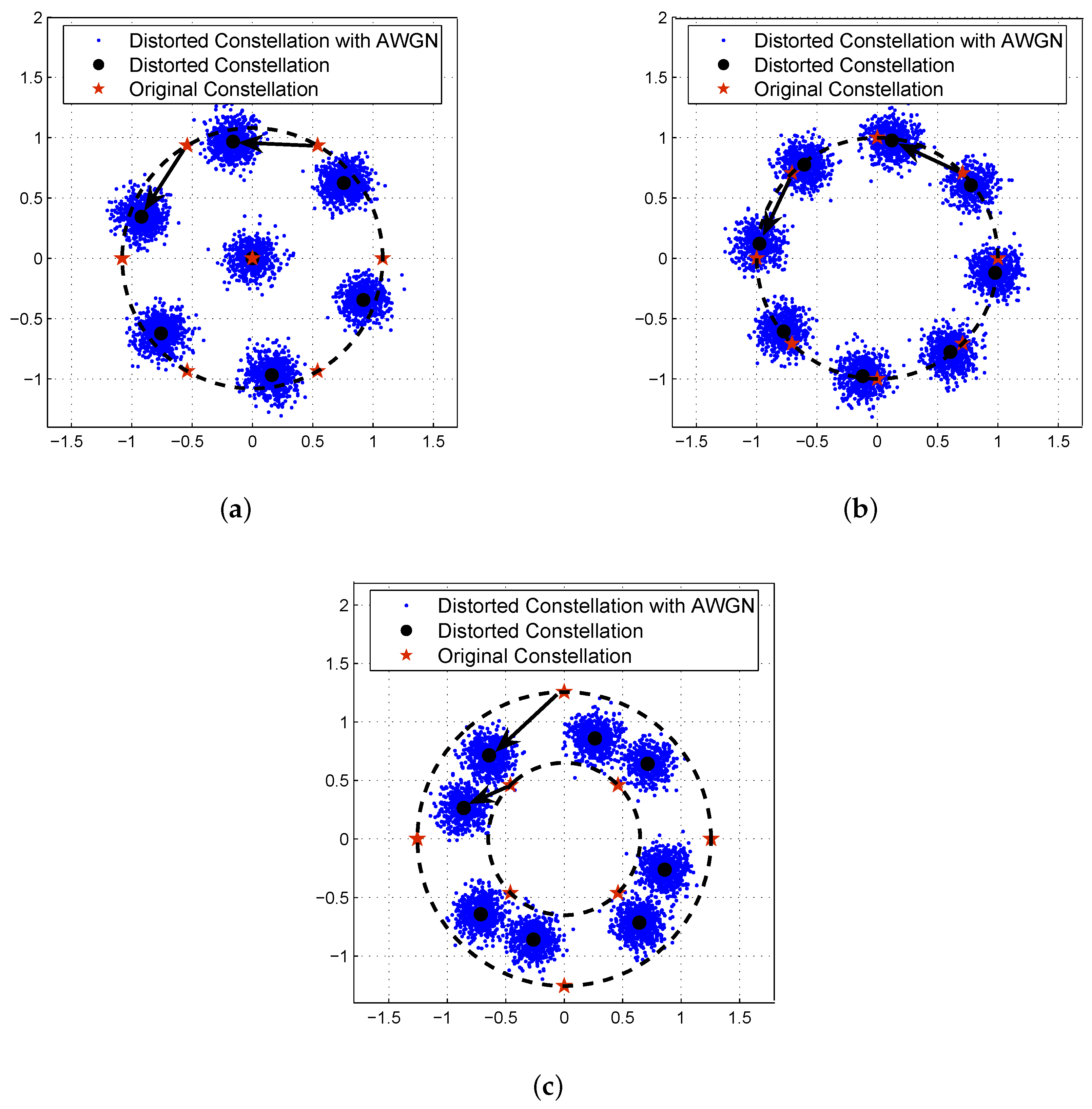
3.3. Analysis of Constellation Distortion

If the modulated signals are sensitive to the non-linear characteristic of the HPA, the resulting non-linear distortion would reduce the overall performance gain expected with the application of higher modulation orders. In order to analyze the sensitivity of 7-QAM signals to the non-linear effects, the distorted constellation diagrams of different modulation methods over the non-linear satellite channel model are presented in Figure 5. In addition, the characteristic parameters in the Saleh model, presented in Equations (3) and (4), for the non-linear conversion module are set as α a = 1.9638 , β a = 0.9945 , α p = 2.5293 and β p = 2.8168 in these simulations [32].
In Figure 5, the arrow points from the original constellation point to its corresponding distorted signal point through the non-linear channel model. Over the non-linear satellite channel model, the 8-QAM signals shown in Figure 5c have serious non-linear distortion in both amplitude and phase. The 8-PSK modulated signals shown in Figure 5b are changed a bit in amplitude but are shifted much in phase. The signals mapped to the signal point on the origin of 7-QAM constellation remain constant in both phase and amplitude, and the other 7-QAM signals are compressed a little more than the 8-PSK signals and also have much distortion in phase. Because of the larger θ min , the 7-QAM signals are less sensitive to the AM/PM distortion than both the 8-PSK signals and the 8-QAM signals.
In summary, although the 8-PSK signals are robust to the non-linear AM/AM conversion, they are poor at the anti-noise performance and the tolerance of the AM/PM distortion. The 7-QAM signals have much better anti-noise performance and are mildly influenced by the AM/AM conversion and the AM/PM conversion, so that the 7-QAM signals may have better error performance over the non-linear channel model than the 8-PSK signals and 8-QAM signals.

4. Combined with NB-LDPC Codes over GF(7)

The new 7-QAM constellation is combined with NB-LDPC codes over GF(7) in this paper. Generally, the NB-LDPC code defined over GF(q) can be represented using an M × N parity check matrix, whose elements are defined over GF(q). We construct the parity check matrix H of NB-LDPC codes over GF(7) by replacing nonzero elements in the parity check matrix of LDPC codes over GF(2) with the nonzero elements of GF(7). In addition, the binary parity check matrix is formed from a binary base matrix using the matrix expansion.
Construction begins with an m b × n b binary base matrix after degree distribution optimization [33], denoted as H bm , which can be written as
H bm = b 0 , 0 b 0 , 1 b 0 , n b - 1 b 1 , 0 b 1 , 1 b 1 , n b - 1 b m b - 1 , 0 b m b - 1 , 1 b m b - 1 , n b - 1 ,
where b i , j GF(2). The next specific steps of construction are as follows:
(i) 
Replace the elements ‘0’ and ‘1’ in H bm with ‘-1’ and the number of the set 0 , 1 , 2 , u - 1 , where u is the expansion ratio. The resulting matrix can be written as
H r = p 0 , 0 p 0 , 1 p 0 , n b - 1 p 1 , 0 p 1 , 1 p 1 , n b - 1 p m b - 1 , 0 p m b - 1 , 1 p m b - 1 , n b - 1 ,
where p ( i , j ) - 1 , 0 , 1 , , u - 1 .
(ii) 
Extend the element in H r into a u × u matrix for the M × N binary parity check matrix H b , which can be expressed as
H b = P p ( 0 , 0 ) P p ( 0 , 1 ) P p ( 0 , n b - 1 ) P p ( 1 , 0 ) P p ( 1 , 1 ) P p ( 1 , n b - 1 ) P p ( m b - 1 , 0 ) P p ( m b - 1 , 1 ) P p ( m b - 1 , n b - 1 ) ,
where M = m b × u , N = n b × u and P p ( i , j ) is a u × u zero matrix as p ( i , j ) = - 1 or a u × u matrix obtained by right cyclically shifting the identity matrix according to the value of p ( i , j ) .
(iii) 
Replace the nonzero element in H b with the nonzero element of GF(7). The obtained matrix can be written as
H = q 0 , 0 q 0 , 1 q 0 , N - 1 q 1 , 0 q 1 , 1 q 1 , N - 1 q M - 1 , 0 q M - 1 , 1 q M - 1 , N - 1 ,
where q i , j GF(7). That is, the obtained matrix H is a parity check matrix of NB-LDPC codes over GF(7).
At the transmitter, the information symbols defined over GF(7) are first encoded using the encoding method with the obtained parity check matrix in the encoder. Then, the codewords are mapped to the 7-QAM constellation.
At the receiver, the received signal y ( t ) is processed using the soft demapping method for the calculation of likelihood information of each symbol. The probability distribution for the AWGN channel can be expressed as
P ( y l x a ) = 1 2 π σ 2 exp - y l - x a 2 2 σ 2 ,
where a = 0 , 1 , , 6 , x a is the a-th point on the 7-QAM constellation, and y l is the l-th received symbol. Then, we use the belief propagation (BP) algorithm over GF(7) in the probability domain to recover the original information symbols in the LDPC decoder [34]. In addition, the initial probability of the l-th received symbol to be symbol a, denoted as f l a , are calculated using the symbol likelihood information, which can be written as
f l a = P ( y l x a ) i = 0 6 P ( y l x i ) = exp - y l - x a 2 2 σ 2 i = 0 6 exp - y l - x i 2 2 σ 2 .
Moreover, the complexity analysis of the NB-LDPC coded 7-QAM scheme is carried out in two aspects, and the benchmark scheme is the combination of 8-PSK (or 8-QAM) and NB-LDPC codes over GF(8). The first aspect is on the symbol demapping complexity at the receiver. With the same soft demodulation methods, each received symbol in the NB-LDPC coded 7-QAM scheme needs to calculate the likelihood information of seven-dimension vector, while the symbol likelihood information for each 8-PSK (or 8-QAM) symbol is an eight-dimensional vector. Therefore, the computation complexity for demapping is similar. The second aspect is on the complexity of decoding. The BP decoding algorithm can be used for both types of NB-LDPC codes. Due to the same decoding algorithm is used, the decoding complexity is similar, though some more efficient processing schemes can be performed on the NB-LDPC codes over GF(8) [35].

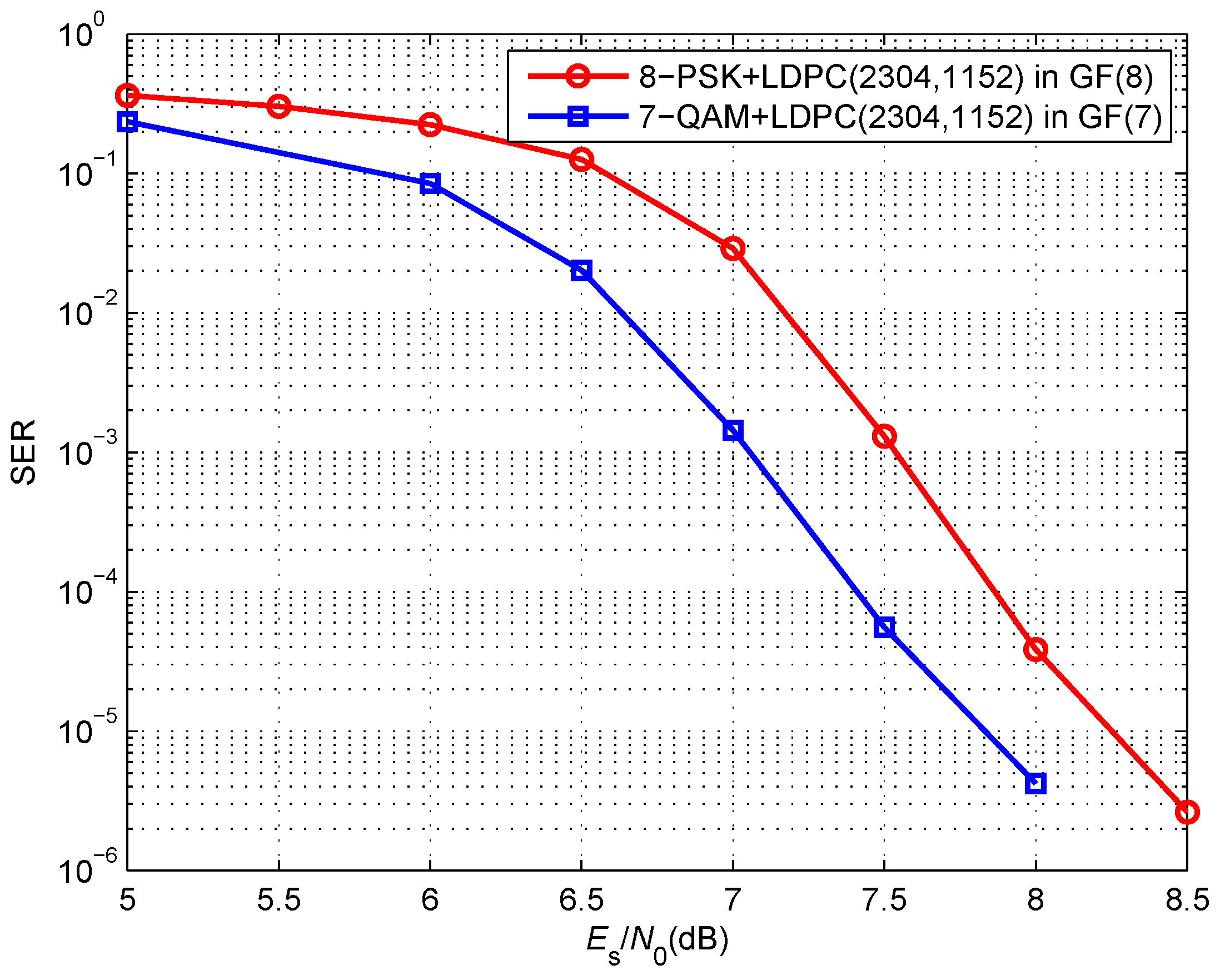
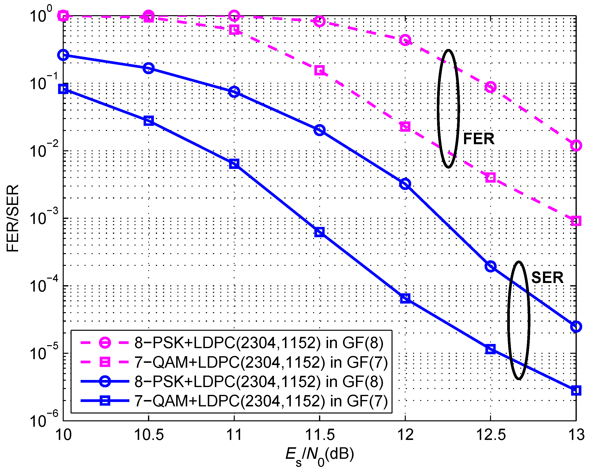
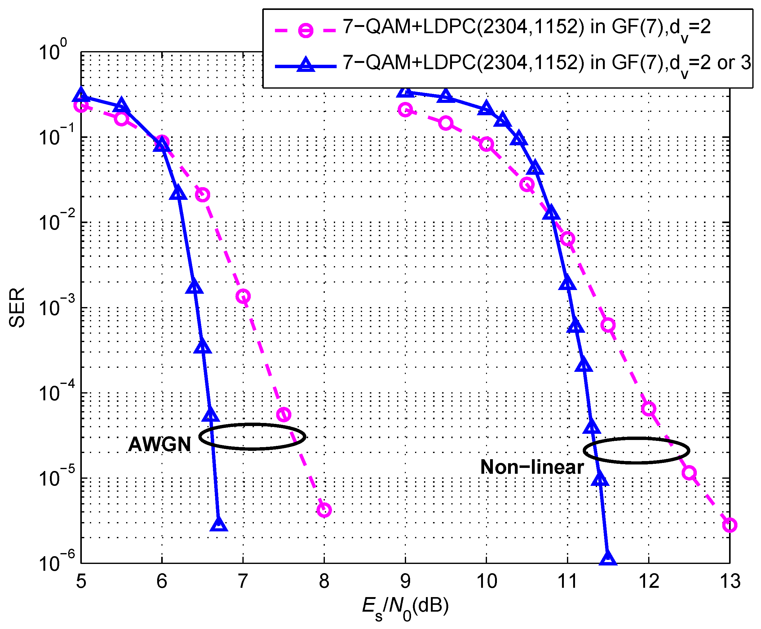
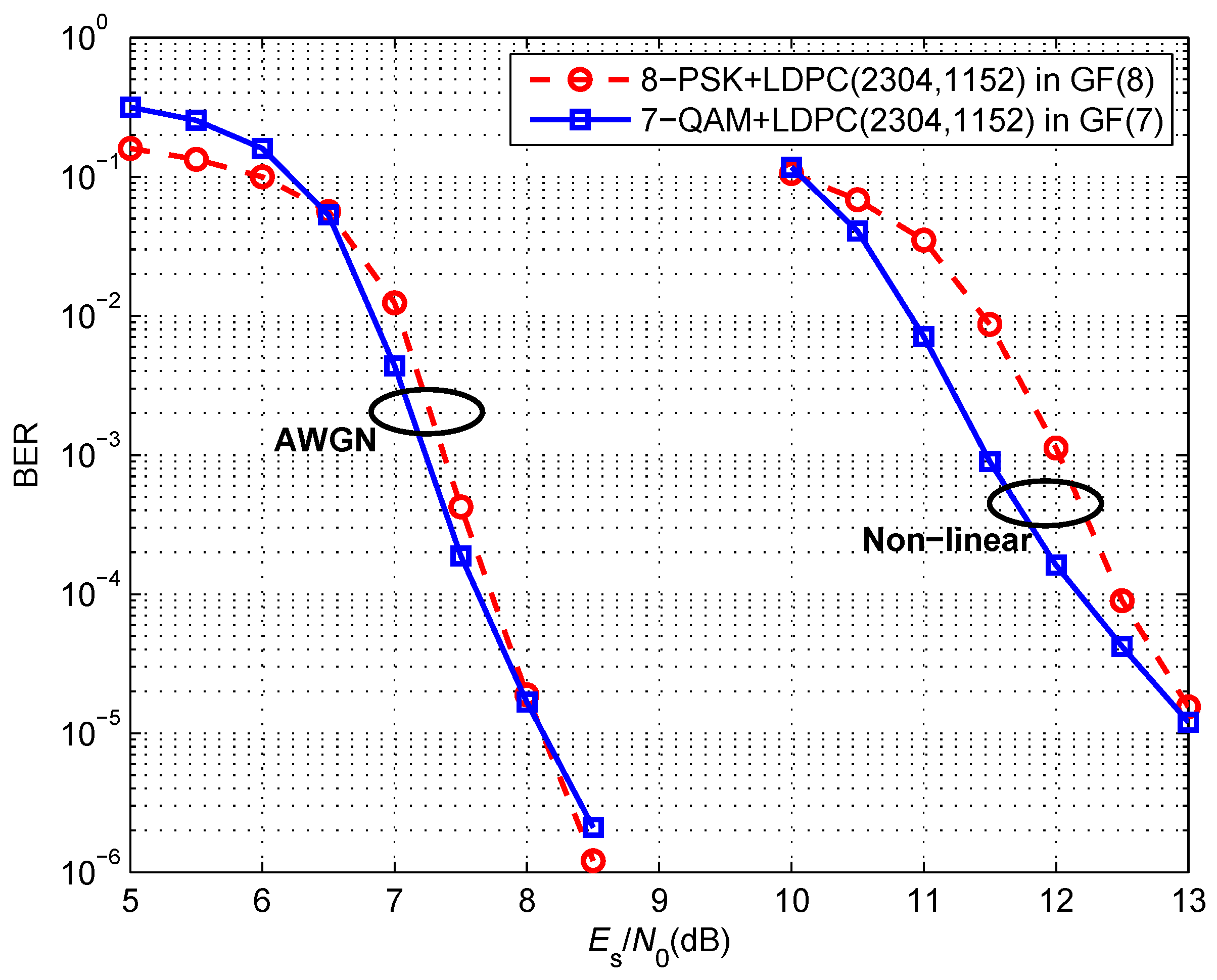
5. Simulation Results

In order to verify the error performance of the proposed coded modulation scheme over the non-linear satellite channel, the performance simulation and comparative analysis between the proposed NB-LDPC coded 7-QAM scheme and the NB-LDPC coded 8-PSK scheme are carried out in this section. The two NB-LDPC codes used to combine with the 7-QAM and the 8-PSK in the simulation are with the code rate of 1 / 2 , the code length of 2304 symbols over GF(7) or GF(8), the row weight d c of 4, and the column weight d v of 2. In addition, the two codes share the same graph structure in the parity check matrix, that is, the position of non-zero elements in the matrix is the same and only the non-zero element sets are different. Therefore, the comparison is relatively fair because the performance of NB-LDPC codes is highly related to the graph structures. In addition, the iteration times for decoding are all set to 20.
First, the SER of 8-PSK, 8-QAM and 7-QAM are simulated over the AWGN channel without channel coding. The simulation results and the average SEP of 7-QAM computed using Equation (21) are presented in Figure 6. It can be observed in Figure 6 that there is a coincidence between analytical and simulation results of 7-QAM at practical SNRs, which proves the correctness of Equation (21). In addition, at SER = 10 - 6 , compared with the demodulation thresholds of 8-PSK and 8-QAM, that of 7-QAM has nearly 3 dB and 1.4 dB gain, respectively. That is, the simulation results are the same as the theoretical analysis, which proves that the 7-QAM constellation has better anti-noise performance than 8-QAM and 8-PSK constellations.
Second, the SERs of the proposed coded modulation scheme and the NB-LDPC coded 8-PSK modulation scheme are simulated over the AWGN channel. As the simulation results shown in Figure 7, compared with the SER of NB-LDPC coded 8-PSK modulation scheme, the proposed scheme also has nearly 0.5 dB gain at SER = 10 - 5 .
Third, the error performance of the two schemes are simulated over the non-linear satellite channel, and the characteristic parameters in Equations (3) and (4) are set as α a = 2.1587 , β a = 1.1517 , α p = 4.0033 , and β p = 9.1040 given in [32]. As the simulation results shown in Figure 8, under the non-linear satellite channel model, compared with the NB-LDPC coded 8-PSK modulation scheme, the proposed scheme is with 0.8 dB performance gain at frame error rate (FER) of 10 - 2 , and it also has a 0.6 dB performance gain at SER of 10 - 5 . Thereby, the 7-QAM constellation has a better error performance over the non-linear channel because of its larger phase difference, which makes it less sensitive to the AM/PM distortion.
Fourth, the SERs of 7-QAM combined with two different LDPC codes are simulated over both the AWGN channel and the non-linear satellite channel for the sensitivity analysis of LDPC codes to the non-linear effects. We construct another NB-LDPC code over GF(7) with the same code length and code rate, and different graph structure of the parity check matrix. Specifically, in the parity check matrix of the second 7-ary LDPC code, d c = 5 , and d v = 2 or 3. Therefore, the second code has better error correction performance than the LDPC code with d v = 2 . As shown in Figure 9, the performance differences between two schemes over the AWGN channel and the non-linear channel are generally the same. It verifies that the error performance of the scheme can be improved by using codes with better error correction performance and would be rarely interfered by the non-linear effect.
Finally, due to the fact that the information data are usually assumed to be binary, the bit error rate (BER) is generally used for the error performance comparison between two schemes, and the BERs of the two scheme over the AWGN channel and the non-linear satellite channel are also given in Figure 9. The conversion of binary symbol set to septinary symbol set should introduce some amount of redundancy as 2 and 7 are both prime numbers. Nevertheless, because of 14 log 2 2 5 log 2 7 0.997 , we convert every 14 binary symbols to five septinary symbols to make the redundancy associated with this conversion be negligible. The simulation results shown in Figure 10 present the 7-QAM as having better performance at low SNR and has a 0.5 dB gain at BER = 10 - 3 over the non-linear channel. However, because of the conversion redundancy and error propagation, the BER curves of the two schemes are getting closer under both the AWGN channel and the non-linear channel as the SNR increases. Despite this, the FER is the primary indicator to evaluate the performance of a scheme, so that we still consider that the proposed scheme has a better performance than the NB-LDPC coded 8-PSK modulation scheme, especially under the non-linear channel.

6. Conclusions

In this paper, considering the requirements of improving the data rate and spectral efficiency of the satellite communication system and the non-linear characteristic of the HPA, we develop a new 7-point constellation and adapt it to NB-LDPC codes over GF(7). First, we give the design and performance theoretical analysis of the 7-QAM constellation. The analysis demonstrates its PAPR, the derivation of its exact expression for the SEP over the AWGN channel, and its insensitivity to the AM/AM conversion of non-linear distortions introduced by the HPA. Then, NB-LDPC codes over GF(7) are combined with 7-QAM to guarantee the reliability of the data transmission. The simulation results illustrate that 7-QAM has a much lower demodulation threshold than 8-QAM and 8-PSK, and the proposed NB-LDPC coded 7-QAM scheme is suitable for the satellite communication system because of its better error performance than NB-LDPC coded 8-PSK scheme over the non-linear channel model.

Author Contributions

Conceptualization, Y.L. and W.C.; methodology, W.C., A.W. and C.H.; software, Y.L.; formal analysis, Y.L. and W.C.; investigation, Y.L. and W.C.; writing—original draft preparation, Y.L.; writing—review and editing, W.C., A.W., and C.H.

Funding

This research was funded in part by the National Natural Science Foundation of China Grant No. 61671324 and the Director’s Funding from the Pilot National Laboratory for Marine Science and Technology (Qingdao).

Conflicts of Interest

The authors declare no conflict of interest.

References

  1. Simons, R.N. Link analysis of high-throughput spacecraft communication systems for future science missions antenna applications corner. IEEE Antennas Propag. Mag. 2016, 58, 66–73. [Google Scholar] [CrossRef]
  2. Dimitrov, S. Nonlinear distortion cancellation and symbol-based equalization in satellite forward links. IEEE Trans. Commun. 2017, 16, 4489–4502. [Google Scholar] [CrossRef]
  3. Layton, K.J.; Mehboob, A.; Akhlaq, A.; Bagaglini, F.; Cowley, W.G.; Lechner, G. Predistortion for wideband nonlinear satellite downlinks. IEEE Commun. Lett. 2017, 21, 1985–1988. [Google Scholar] [CrossRef]
  4. Xue, R.; Yu, H.; Cheng, Q. Adaptive coded modulation based on continuous phase modulation for inter-satellite links of global navigation satellite systems. IEEE Access 2018, 6, 20652–20662. [Google Scholar] [CrossRef]
  5. Anedda, M.; Meloni, A.; Murroni, M. 64-APSK constellation and mapping optimization for satellite broadcasting using genetic algorithms. IEEE Trans. Broadcast. 2016, 62, 1–9. [Google Scholar] [CrossRef]
  6. Cronie, H.S. Signal shaping for bit-interleaved coded modulation on the AWGN channel. IEEE Trans. Commun. 2011, 58, 3428–3435. [Google Scholar] [CrossRef]
  7. Meloni, A.; Murroni, M. On the genetic optimization of APSK constellations for satellite broadcasting. In Proceedings of the 2014 IEEE International Symposium on Broadband Multimedia Systems and Broadcasting, Beijing, China, 25–27 June 2014. [Google Scholar] [CrossRef]
  8. Kayhan, F.; Montorsi, G. Constellation design for transmission over nonlinear satellite channels. In Proceedings of the 2012 IEEE Global Communications Conference (GLOBECOM), Anaheim, CA, USA, 3–7 December 2012; pp. 3401–3406. [Google Scholar] [CrossRef]
  9. Dalakas, V.; Papaharalabos, S.; Mathiopoulos, P.T.; Candreva, E.A.; Corazza, G.E.; Vanelli-Coralli, A. BICMC and TD comparative performance study of 16-APSK signal variants for DVB-S2 systems. IEEE Commun. Lett. 2015, 19. [Google Scholar] [CrossRef]
  10. Sung, W.; Kang, S.; Kim, P.; Chang, D.; Shin, D. Performance analysis of APSK modulation for DVB-S2 transmission over nonlinear channels. Int. J. Satell. Commun. Netw. 2009, 27, 295–311. [Google Scholar] [CrossRef]
  11. Richardson, T.J.; Shokrollahi, M.A.; Urbanke, R.L. Design of capacity-approaching irregular low-density parity-check codes. IEEE Trans. Inf. Theory 2001, 47, 619–637. [Google Scholar] [CrossRef]
  12. Liu, T.; Lin, C.; Djordjevic, I. Advanced GF(32) nonbinary LDPC coded modulation with non-uniform 9-QAM outperforming star 8-QAM. Opt. Express 2016, 24, 13866–13874. [Google Scholar] [CrossRef]
  13. Lin, C.; Zou, D.; Liu, T.; Djordjevic, I. Capacity achieving nonbinary LDPC coded non-uniform shaping modulation for adaptive optical communications. Opt. Express 2016, 24, 18095–18104. [Google Scholar] [CrossRef] [PubMed]
  14. Simon, M.; Smith, J. Hexagonal multiple phase-and-amplitude-shift-keyed signal sets. IEEE Trans. Commun. 1973, 21, 1108–1115. [Google Scholar] [CrossRef]
  15. Hosur, S.; Mansour, M.F.; Roh, J.C. Hexagonal constellations for small cell communication. In Proceedings of the IEEE Global Communication Conference (GLOBECOM), Atlanta, GA, USA, 9–13 December 2013; pp. 3270–3275. [Google Scholar] [CrossRef]
  16. Yang, M.; Rastegarfar, H.; Djordjevic, I. Probabilistically coded modulation formats for 5G mobile fronthaul networks. J. Lightwave Technol. 2019, 37, 3882–3892. [Google Scholar] [CrossRef]
  17. Abdelaziz, M.; Gulliver, T.A. Triangular constellations for adaptive modulation. IEEE Trans. Commun. 2018, 66, 756–766. [Google Scholar] [CrossRef]
  18. Forney, G.D.; Gallager, R.; Lang, G.; Longstaff, F.M.; Qureshi, S.U. Efficient modulation for band-limited channels. IEEE J. Sel. Areas Commun. 1984, 2, 632–647. [Google Scholar] [CrossRef]
  19. Tanahashi, M.; Ochiai, H. A multilevel coded modulation approach for hexagonal signal constellation. IEEE Trans. Wirel. Commun. 2009, 8, 4993–4997. [Google Scholar] [CrossRef]
  20. Singya, P.K.; Kumar, N.; Bhatia, V.; Alouini, M.S. On performance of hexagonal cross and rectangular QAM for multi-relay systems. IEEE Access 2019, 7, 60602–60616. [Google Scholar] [CrossRef]
  21. Hu, X.Y.; Eleftheriou, E. Binary representation of cycle tanner-graph GF(2q) codes. Proc. IEEE Int. Conf. Commun. 2004, 1, 528–532. [Google Scholar] [CrossRef]
  22. Szczecinski, L.; Aissa, S.; Gonzalez, C.; Bacic, M. Exact evaluation of bit- and symbol-error rates for arbitrary 2D modulation and nonuniform signaling in AWGN channel. IEEE Trans. Commun. 2006, 54, 1049–1056. [Google Scholar] [CrossRef]
  23. Noda, S.; Koike, S. Optimum binary to symbol coding for 6PSK and bit error rate performance. In Proceedings of the 2007 IEEE Wireless Communications and Networking Conference, Kowloon, China, 11–15 March 2007; pp. 509–513. [Google Scholar] [CrossRef]
  24. Cay, A.; Popescu, D.C. On the probability of symbol error for two-dimensional signal constellations with non-uniform decision regions. In Proceedings of the 2012 46th Annual Conference on Information Sciences and Systems (CISS), Princeton, NJ, USA, 21–23 March 2012. [Google Scholar] [CrossRef]
  25. Park, S.J. Performance analysis of triangular quadrature amplitude modulation in AWGN channel. IEEE Commun. Lett. 2012, 16. [Google Scholar] [CrossRef]
  26. Rugini, L. Symbol error probability of hexagonal QAM. IEEE Commun. Lett. 2016, 20, 1523–1526. [Google Scholar] [CrossRef]
  27. Li, J.; Zhang, X.D.; Beaulieu, N.C. Precise calculation of the SEP of 128- and 512-cross-QAM in AWGN. IEEE Commun. Lett. 2008, 12, 1–3. [Google Scholar] [CrossRef]
  28. Beaulieu, N.C.; Chen, Y. Closed-form expressions for the exact symbol error probability of 32-cross-QAM in AWGN and in slow nakagami fading. IEEE Commun. Lett. 2007, 11, 310–312. [Google Scholar] [CrossRef]
  29. Aggarwal, S. A survey-cum-tutorial on approximations to Gaussian Q function for symbol eerror probability analysis over nakagami- m fading channels. IEEE Commun. Surv. Tutor. 2019, 21, 2195–2223. [Google Scholar] [CrossRef]
  30. Kumar, N.; Singya, P.K.; Bhatia, V. ASER analysis of hexagonal and rectangular QAM schemes in multiple-relay networks. IEEE Trans. Veh. Technol. 2018, 67, 1815–1819. [Google Scholar] [CrossRef]
  31. Cianca, E.; Rossi, T.; Yahalom, A.; Pinhasi, Y.; Farserotu, J.; Sacchi, C. EHF for satellite communications: The new broadband frontier. Proc. IEEE 2011, 99, 1858–1881. [Google Scholar] [CrossRef]
  32. Saleh, A.A.M. Frequency-independent and frequency-dependent nonlinear models of TWT amplifiers. IEEE Trans. Commun. 1981, 29, 1715–1720. [Google Scholar] [CrossRef] [Green Version]
  33. Poulliat, C.; Fossorier, M.; Declercq, D. Design of regular (2,dc)-LDPC codes over GF(q) using their binary images. IEEE Trans. Commun. 2008, 56, 1626–1635. [Google Scholar] [CrossRef]
  34. Han, G.; Guan, Y.L.; Huang, X. Check node reliability-based scheduling for BP decoding of non-binary LDPC codes. IEEE Trans. Commun. 2013, 61, 877–885. [Google Scholar] [CrossRef]
  35. Declercq, D.; Fossorier, M. Decoding algorithms for non-binary LDPC codes over GF(q). IEEE Trans. Commun. 2007, 55, 633–643. [Google Scholar] [CrossRef]
Figure 1. The non-linear channel model.
Electronics 08 01396 g001
Figure 2. Constellation diagrams. (a) 7-QAM; (b) 8-PSK; (c) 8-QAM.
Electronics 08 01396 g002
Figure 3. The decision regions of 7-QAM constellation points.
Electronics 08 01396 g003
Figure 4. Schematic diagram for division of unconventional regions. (a) RT region; (b) decision region of signal point ‘1’.
Electronics 08 01396 g004
Figure 5. Original and distorted constellation diagrams. (a) 7-QAM; (b) 8-PSK; (c) 8-QAM.
Electronics 08 01396 g005
Figure 6. SER performance of different modulations over the AWGN channel without channel coding and the average SEP of 7-QAM.
Electronics 08 01396 g006
Figure 7. SER of different modulations combined with NB-LDPC codes over the AWGN channel.
Electronics 08 01396 g007
Figure 8. FER and SER of different modulations combined with NB-LDPC codes over the non-linear satellite channel.
Electronics 08 01396 g008
Figure 9. SER of 7-QAM combined with different NB-LDPC codes over different channels.
Electronics 08 01396 g009
Figure 10. BER of different modulations combined with NB-LDPC codes over different channels.
Electronics 08 01396 g010
Table 1. Parameters of three constellations.
Constellation θ min d min
7-QAM π / 3 2 R 1 sin π 6 1.0801
8-PSK π / 4 2 R 2 sin π 8 0.7654
8-QAM π / 4 2 R 3 sin π 4 0.9194
Table 2. PAPRs of three constellations.
Constellation E s E max PAPR
7-QAM 24 d 2 / 7 4 d 2 1.1667
8-PSK d 2 / sin 2 π / 8 d 2 / sin 2 π / 8 1
8-QAM 3 + 3 d 2 4 + 2 3 d 2 1.5774

