Article

An Efficient Connected Dominating Set Clustering Based Routing Protocol with Dynamic Channel Selection in Cognitive Mobile Ad Hoc Networks

1
Department of Electronics and Computer Engineering in Graduate School, Hongik University, Sejong 30016, Korea
2
Department of Software and Communications Engineering, Hongik University, Sejong 30016, Korea
*
Author to whom correspondence should be addressed.
Electronics 2019, 8(11), 1332; https://doi.org/10.3390/electronics8111332
Submission received: 21 October 2019 / Revised: 6 November 2019 / Accepted: 7 November 2019 / Published: 11 November 2019
(This article belongs to the Section Networks)

Abstract

:
In mobile ad-hoc networks (MANETs), nodes are mobility naturally which renders a great challenge in topology controls. Connected dominating set (CDS) has been considered as an efficient solution to solve such a problem by constructing a virtual backbone network to achieve the scalability and efficiency of wireless networks. In this paper, we propose an efficient connected dominating set clustering based routing protocol with dynamic channel selection (CRD) in multi-channel cognitive radio MANETs to obtain high packet delivery ratio (PDR), low control overheads, low delay and low energy consumption when node is moving in high speed. Moreover, CRD protocol can apply for Vehicular Ad Hoc Network, IoT and 5G. The proposed CRD protocol includes clustering and routing phases under multi-channel cognitive radio approach. In the clustering phase, we propose CDS selection, CDS size reduction and CDS based clustering algorithms to formulate clusters and provide a set of intermediate nodes which is latter used as a route searching space for the routing phase. In the routing phase, a sending channel based focus region selection (CFS) algorithm is adopted dynamically to establish an efficient route from a set of intermediate nodes that avoids the affected region of a primary user. The CRD routing protocol is then implemented in environmental conditions close to reality (OMNET++ platform) to demonstrate its superiority over the conventional AODV protocol in terms of PDR, control overhead, delay and energy consumption.

1. Introduction

Cognitive radio (CR) is an intelligent technology to improve the spectrum utilization in mobile ad-hoc networks (MANETs) by allowing cognitive users flexibly use the spectrum allocated to licensed primary users. In this approach, each cognitive user can sense status of channels and immediately switch to vacant channels to avoid interfering with primary users or other users [1,2]. Hence, CR has been considered as a promising technology to improve the spectrum utilization in CR-MANETs. There are three main cognitive radio network paradigms: underlay, overlay and interweave. In underlay systems, cognitive (secondary) user knows the channel strengths to primary users and can transmit simultaneously with primary user as long as interference caused is below an acceptable limit. Moreover, the transmit power of cognitive user is limited by the interference constraint. In overlay systems, cognitive users know channel gains, codebooks and the message of the primary users. Each cognitive user can transmit simultaneously with primary user. The interference to primary user can be offset by using part of the power of cognitive user to relay the primary user’s message. Moreover, cognitive user can transmit at any power, the interference to primary user can be offset by relaying the primary user’s message. In interweave systems, cognitive user knows the spectral holes in space, time, or frequency when primary user is not using these holes. Each cognitive user can transmit simultaneously with a primary user only in the event of false spectral hole detection. Moreover, the transmit power of cognitive user is limited by the range of its spectral hole sensing. In our paper, we considered the system model as a overlay system.
There are many challenges for clustering and routing in MANET such as no fixed infrastructure, decentralized management, dynamic topology, limited bandwidth, limited resources, limited physical security, poor transmission quality, dynamic connection and disconnection of the links and updating information of dynamic links among nodes. In this paper, we focus on clustering and routing issues in network layer. However, there exist important issues of lower layers which can be occured at network layer such as throughput, energy efficiency, traffic optimization, packet loss, security, delay, QoS, admission control, mobility, routing and data gathering. These issues significantly impact to the routing process in network layer. However, we mainly focus on establishing the best route in network layer to improve packet delivery ratio (PDR), control overheads, delay and energy consumption. Thus, we assume that these above issues were fully supported by lower layers, that is, physical and data link layers.
Since MANET is a mobile environment which does not depend on any fixed infrastructure or centralized management, clustering approach is an efficient approach to design virtual infrastructures and make routing process stable [3]. In this paper, we focus on clustering and routing problems with multi-channel to improve network performance in CR-MANETs. In routing process, routes established at the network layer will affect significantly the licensed channel of primary users, arising a challenging problem in guaranteeing quality of service in MANETs. CR technology is adopted for routing process by enabling channel selection and transmission direction to solve such a problem. However, the impacts of clustering and routing problems with channel selection and transmission direction on multi-channel cognitive MANETs, which cover a lot of attractive research problems, have received less attention in the literature.
In this section, we discuss the recent works on clustering and routing algorithms in MANETs. In Reference [4], the authors presented that typical clustering schemes of MANETs were classified into six categories such as dominating-set-based (DS-based) clustering, low-maintenance clustering, mobility-aware clustering, energy-efficient clustering, load-balancing clustering and combined-metrics-based clustering. Particularly, the idea of DS-based clustering is to find a connected set of dominating nodes (CDS) with a minimum size. The obtained CDS is used as a routing space for routing process. In low-maintenance clustering approach, the main goal of clustering is to provide a stable cluster architecture by minimizing re-clustering situations. This issue helps to save the cost of clustering process. The main task of mobility-aware clustering is also to construct a stable cluster structure. The main idea of this clustering approach is that mobile nodes are classified into groups based on the movement of node. In energy-efficient clustering scheme, a MANET should try to save its energy consumption in order to prolong the network lifespan. Because a cluster head has to handle more tasks than a member, its energy is easily exhausted and network communication may be interrupted. There are some approaches to solve this problem such as limiting the time that a mobile node can serve as a cluster head continuously, guaranteeing the CDS connected and removing unnecessary mobile nodes with low energy level from the CDS and serving slave nodes as many as possible and minimizing the total energy consumption between all communicating master-slave pairs, where a master is a cluster head and a slave is a member. Load-balancing clustering algorithms provides an optimum number of clusters to improve the system performances. The number of mobile nodes in each cluster is set by an upper and a lower limit. When a cluster size exceeds its limit, the number of mobile nodes is adjusted by re-clustering. The main idea of combined-metrics-based clustering is to produce a weighted function which is a combination of parameters such as node degree, residual energy capacity, moving speed. This weighted function is used for the cluster heads selection process to obtain a cluster structure, which improves the system performances. In Reference [5], the authors proposed a probabilistic clustering algorithm. In this algorithm, a node with more vacant channels has a higher probability to become a cluster head. Next, each CH broadcasts their list of vacant channels. If a node has one or more common channels with a CH, it sends a join request message including its vacant channels’ list and ID to the cluster head. Finally, each cluster head decides a final communication channel based on the received channel lists from non-cluster head nodes. In Reference [6], a weighted function was proposed by combining the degree of connectivity, mobility, time of a cluster head (CH) and sum of distances to neighbors to elect cluster heads in MANETs. A distributed weighted clustering algorithm (DWCA) was presented in Reference [7] to optimize the configuration and power for the cluster heads in MANETs. In Reference [8], a weighted clustering algorithm was studied, called enhancement on weighted clustering algorithm (EWCA). In EWCA, transmission power, transmission range, mobility and battery energy parameters were used to elect CHs and achieve the load balancing to enhance the stability of clusters in MANETs. A mobility based clustering approach was proposed in Reference [9] to support mobility management and multicast routing in MANETs. Topology control is a challenging problem because there is no fixed infrastructure in MANETs, the connected dominating set (CDS) has been considered as an effective approach to design clusters and virtual backbones in MANETs [10]. In Reference [11], a CDS based distributed algorithm was proposed based on node IDs to reduce the size of CDS. A reduction-based methods were presented in References [12,13] to find a CDS from one node with maximum vertex degree and some rules were also introduced to reduce the size of CDS. To construct a CDS for routing protocol, an algorithm with rules based on energy level and degree of nodes was proposed in Reference [14]. The authors of Reference [15] proposed an energy efficient and salable routing algorithm based on length of route and remaining energy for extreme emergency ad hoc communications. In Reference [16], the authors proposed an efficient flooding and repairing local route algorithm based on a stable connected dominating set in MANETs. In this algorithm, if a node has minimum velocity and maximum signal strength, it is selected as a dominator.
Besides, several studies on the routing issue were presented as follows. In Reference [17], the authors proposed a distributed interference-aware relay selection (DIRS) algorithm for IEEE 802.11-based wireless networks with multiple source–destination pairs. Each source–destination pair selects best relay by using inter-node interference and channel statistics without the knowledge of topology information. In DIRS algorithm, inter-node interference can be minimized by optimising relay selection. In Reference [18], the authors proposed a new multi-channel MAC protocol to solve the channel assignment and medium access problems in an integrated manner. In this protocol, each mobile host was assigned a common channel for control purpose and it switched to remaining channels for data exchange. In Reference [19], the authors proposed an optimization methodology to analytically calculate the end-to-end throughput capacity of IEEE 802.11-based multi-hop wireless networks. The proposed methodology provided a very accurate calculation of the end-to-end throughput capacity by considering the node interference, the impact of hidden node collision and multi-rate terminals. In Reference [20], this article addressed a number of problems when implementing two routing protocols on actual wireless networks. There was no protocol which provided a stable multi-hop route. Based on the authors’ experiences, several outlines are recommended for future work in MANET researches. Most of routing protocols in cognitive mobile ad hoc networks have recently considered in dynamic spectrum allocation and path establishment by observing primary user activity regions in Reference [21]. Layered graphs were utilized to model multi-channel networks [22] and colored graphs were deployed for model spectrum sharing and allocation problems [23]. In Reference [24], a cognitive ad hoc on-demand distance vector (CAODV) protocol was proposed based on the ad hoc on-demand distance vector (AODV) protocol. Both route formation and packet discovery of the CAODV avoids the affected region of primary user. Moreover, the CAODV applies joint path and channel selection at each forwarder to minimize the route cost. This protocol broadcasts the route request packet to neighbors on all the channels that leads to increase control overheads and reduce network life time. In Reference [25], the authors proposed a distributed prediction-based cognitive topology control (PCTC) scheme which is a middle-ware approach (between the cognitive radio module and routing). The PCTC uses cognitive link availability prediction to aware the affected region of primary users and to predict the available duration of links in CR-MANETs. The PCTC constructs efficient and reliable topology in order to reduce re-routing and improve end-to-end network performance. In Reference [26], the authors proposed a SEARCH routing protocol for CR-MANETs to find a route subject to minimum end-to-end delay from the source to the destination without affecting primary user activities. Aiming at improving network throughput and mitigating interference to primary users, various routing problems are formulated based on graph theory [27,28,29]. In particular, the authors of Reference [27] introduced a mixed integer non-linear programming to minimize spectrum usage and aggregate interference from cognitive users to a primary user. In Reference [28], a routing and dynamic spectrum allocation (ROSA) algorithm was proposed subject to spectrum allocation, scheduling and transmission power control scheme to maximize network throughput and limit physical interference to other users. Based on interference model, the authors of Reference [29] proposed joint routing, opportunistic spectrum scheduling and time sharing scheduling algorithms to minimize aggregate interference from cognitive users to a primary user. Besides, spectrum availability may change from time to time and hop by hop which is unpredictable. In Reference [30], the authors presented several types of prediction algorithms to forecast the node’s locations. These prediction algorithms with Markov analysis, text compression, user’s movement history and Bayesian and neural networks, significantly improved the system performance in mobile wireless systems. For improving routing reliability and scalability, the authors of Reference [31] used some prediction techniques to efficiently predict time of next movement and the next location of mobile nodes in MANETs. The authors of Reference [32] proposed an energy reduction multipath routing protocol by using a recoil technique (AOMDV-ER) in MANETs to improve the system performances. In AOMDV-ER, the mobile nodes used a varying recoil off time technique to establish the route to their destination based on the geographical location. In Reference [33], the authors proposed a topology change aware-based routing protocol choosing scheme (TARCS) for flying ad hoc networks to improve the system performances. In TARCS, mobile nodes can sense changes of the surrounding network topology periodically to provide a suitable routing protocol. In Reference [34], the authors proposed a node-disjoint multipath routing (NDMR) protocol to establish two node-disjoint paths between a source and a destination in a wireless network in order to solve the unstable state of wireless links, and unpredictable environmental interference. The proposed approach uses the request-reply mechanism to find the node-disjoint paths. In Reference [35], the authors presented a key exchange technique based on the fluctuating topology characteristic of MANETs. The ever changing topology of the network almost completely removes an active attacker’s success ratio by using splitting key exchange information technique.
However, the aforementioned works just focused on clustering or routing separately in conventional MANETs. Since the cost of established routes is greatly expensive, clustering is considered as an effective approach in simplifying routing process and reducing such a cost, that is, the size of routing space is reduced and energy balancing is achieved. In multi-channel cognitive radio environments, cognitive users have to be aware of channel status to establish a route from a source to a destination. Particularly, cognitive users first detect dynamically vacant channels to make a decision of either switching channel or using different regions to avoid the licensed spectrum in the transmission range of primary users [26,28]. To provide comprehensibly the advantages of the proposed CRD protocol compared to the state-of-the art protocol, we summarize the main features in Table 1, where notation “-” is denoted as “not mentioned.”
This paper proposes an efficient connected dominating set clustering based routing protocol with dynamic channel selection (CRD) in multi-channel cognitive mobile ad hoc networks (MCR-MANETs) to obtain high packet delivery ratio (PDR), low control overheads, low delay and low energy consumption when mobile nodes are moving in high speed. Moreover, CRD protocol can apply for Vehicular Ad Hoc Network (VANET), IoT and 5G. The main contributions of the paper can be summarized as follows:
  • We propose a CDS selection and a CDS size reduction algorithms to achieve a set of intermediate nodes which is latter used as a route searching space underlying infrastructure for routing process. Particularly, the CDS selection algorithm provides a CDS while the CDS size reduction algorithm uses some rules and the weighted function to reduce the size of CDS which supports the cluster process more effective.
  • We next propose a CDS based clustering algorithm to formulate clusters by using the weighted function and a node’s identify for the cluster head election process. Moreover, this algorithm also helps to select the gateways and cluster heads in the set intermediate nodes which makes the routing process more efficient.
  • We develop a sending channel based focus region selection (CFS) algorithm in routing phase to support the intermediate nodes to select dynamically a channel for sending a route request packet which can avoid the affected region of a primary user. A CRD protocol is then proposed to establish a good route from a source to a destination which utilizes the CDS based clustering and CFS algorithms to improve the network performances.
  • We finally implement the proposed CRD protocol in environmental conditions close to reality (OMNET++ platform) to show its superiority over the conventional AODV protocol in terms of PDR, control overhead, delay and energy consumption.
The rest of paper is organized as follows—Section 2 describes system model, energy model and channel model. Section 3 presents the proposed CRD protocol consisting of four subsections, such as basic concepts of the system model, necessary function and definitions, packet structures, underlying technology and the proposed CRD protocol. In the underlying technology subsection, we present necessary algorithms such as the proposed CDS selection, the proposed CDS size reduction, the proposed CDS based clustering. Section 4 evaluates the performances of the proposed protocol in the considered system setup. Finally, Section 5 concludes the paper.

2. System Model

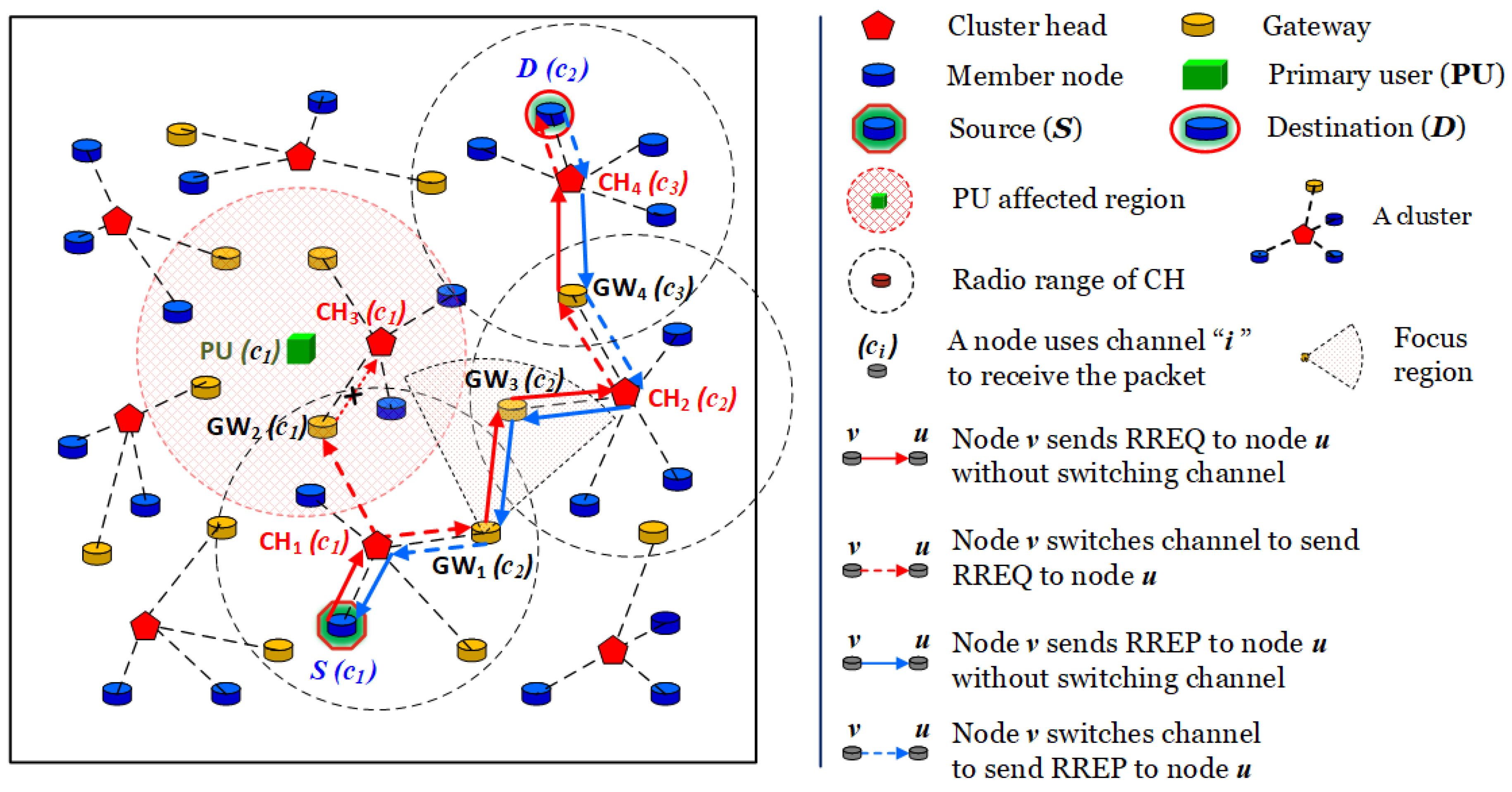
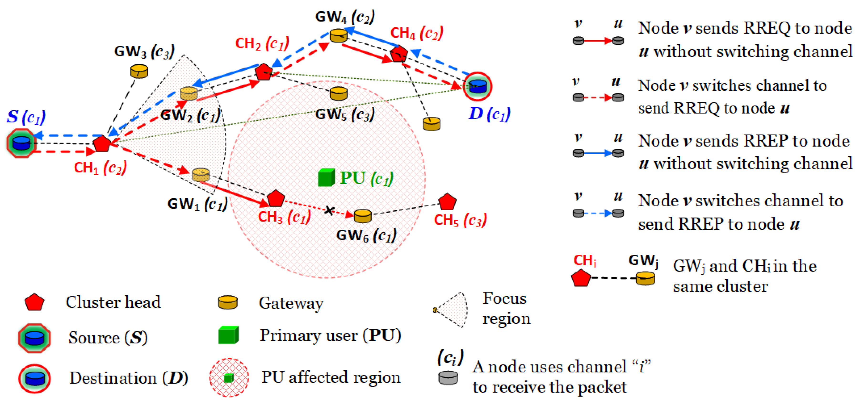
We consider an MCR-MANET consisting of multiple cognitive users (CUs) and a primary user (PU), as shown in Figure 1. The PU operates on a licensed channel and switches randomly to ON mode or OFF mode. When the PU is in the ON mode, cognitive users can not transmit packets on the licensed channel in the affected region of PU. When the PU is in the OFF mode, cognitive users can use the licensed channel to transmit packets in the networks. This paper focuses on addressing the routing problems when the PU is in the ON mode to improve the spectrum utilization in cognitive environment. Moreover, the PU’s mobility follows the random waypoint (RWP) model. In the secondary network, each user can be seen as a mobile node and its properties can be listed as follows:
  • All nodes move randomly in the two-dimension space based on the RWP model.
  • Each node can know the location of the destination and its own location through the global positioning system (GPS) [3,36].
  • The transmission range of nodes is fixed [9].
  • Each node receives packets on a given channel (receiving channel) while it can switch to any channel to send packets.
Moreover, mobile nodes in the secondary network can be classified into groups/clusters. Each cluster has three types of nodes including cluster head, gateway and cluster member, respectively [37]. Firstly, a cluster head (CH) is a representation of a cluster and its tasks are aggregating packets of all cluster members and transmitting the aggregated packet within a single hop. Moreover, CH can directly communicate with a gateway or other CHs. Secondly, a gateway (GW) is an intermediate node which can directly communicate with its CH or CHs/GWs of other clusters within a single hop. Finally, a node in a cluster is a member (CM) if it is neither a cluster head nor a gateway. It only communicates with its CH within a single hop.
Figure 1 describes the operation of cluster head and gateway and cluster member in MCR-MANETs. As can be seen in Figure 1, source S generates a RREQ packet and sends it to CH 1 without switching channel. CH 1 chooses a focus region with sending channel 2 to forward the RREQ to GW 1 and GW 2 . Because GW 2 is in the radio range of PU and PU uses channel 1 as licensed channel, GW 2 can not forward the RREQ packet on channel 1 to CH 3 while GW 1 can choose a focus region to forward the RREQ packet to GW 3 without switching channel. GW 3 continues to forward the RREQ packet to CH 2 without switching channel. CH 2 chooses a focus region with sending channel 3 to forward the RREQ packet to GW 4 . GW 4 continues to forward the RREQ to CH 4 without switching channel. CH 4 switches to channel 2 and forwards the RREQ packet to destination D . When destination D receives the RREQ packet from CH 4 , it generates a RREP packet and switches to channel 3 in order to send the RREP packet to CH 4 . CH 4 continues to forward the RREP packet to GW 4 without switching channel. GW 4 switches to channel 2 and forwards the RREP packet to CH 2 . CH 2 continues to forward the RREP packet to GW 3 without switching channel. GW 3 continues to forward the RREP packet to GW 1 without switching channel. GW 1 switches to channel 1 and forwards the RREP packet to CH 1 . CH 1 continues to forward the RREP packet to source S without switching channel. When source S receives an RREP packet, it sends data to the destination. We note that each node in routing process records the next hop and a sending channel into its routing table, which is used to send data from the source to destination D.
In this paper, we mainly focus on the network layer to establish a route in MANET, where mobile nodes have to exchange their information together by using control packets. The energy consumption is primarily affected by transmitting and receiving control packets. Moreover, the energy consumption of data transmission from a source to a destination mainly depends on transmission energy of sender end reception energy of receiver. Thus, we only consider the transmission energy and reception energy issues that affect clearly on the network layer and considering other energy issues in physical and data link layer is indeed out of the scope of the paper. We apply the energy model in physical layer taken from References [38,39] to evaluate the energy efficiency of the proposed routing protocol. The energy consumption varies from 230 mA in receiving mode to 330 mA in transmitting mode, using a 3.3 V or 5.0 V energy supply. These values correspond to a 2400 MHz WaveLAN implementation of IEEE 802.11. The transmission energy and reception energy (in Joules), denoted by E T X and E R X , respectively, depend on packet size (in bits) and they can be expressed as
E T X = ( 330 × 5 × P a c k e t S i z e ) / ( 2 × 10 6 ) .
E R X = ( 230 × 5 × P a c k e t S i z e ) / ( 2 × 10 6 ) .
In MANETs, multiple channels are usually supported by the modern wireless MAC protocols [40]. For example, it is known that the IEEE 802.11 b/g standard provides 14 channels and each node can use multiple channels to communicate with other nodes. Each node has two transceivers, one is always on common channel 0 for controlling packets while the other one can change its channel number from 1 to N c 1 for transmitting data packets, where N c denotes the total number of channels.

3. The Proposed Routing Protocol—CRD

The operation of the proposed CRD protocol is split into sessions. Each session is divided into two consecutive phases including clustering and routing. In the clustering phase, each node first uses a common channel to exchange necessary information with its neighbors by using HELLO packet. Second, the CDS selection algorithm, as shown in Algorithm 1, is proposed to establish a set of intermediate nodes (CDS). Then the size of CDS can be reduced by using the CDS size reduction algorithm, as shown in Algorithm 2. Finally, cluster heads are elected from the CDS based on the CDS based clustering algorithm, as shown in Algorithm 3. After these processes, the CDS includes intermediate (gateway) nodes and cluster heads, and this CDS is considered as a routing space in routing phase. In the routing phase, we denote v as a node, CH v as the cluster head of v and C ( v ) as the receiving channel of v. The proposed routing algorithm can be explained as follows. First, a source S generates a RREQ packet and sends it to CH S on channel C ( CH S ) . If a gateway/cluster head v receives a RREQ packet, it uses the CFS algorithm, as shown in Algorithm 4, to choose a focus region with a sending channel in order to forward this RREQ packet to another gateway/cluster head. If a destination D receives a RREQ packet, it generates a RREP packet and replies it to the source in order to establish a route which avoids the affected region of the primary user. In summary, the proposed routing algorithm outlined as Algorithm 5.

3.1. Necessary Functions and Definitions

In this subsection, we propose necessary functions and definitions such as mobility relationship function, stability function, remaining energy ratio, speed ratio and packet structures supporting the proposed Algorithms 1–5.
Mobility relationship. Let v be a node. We denote R as the radius of the transmission range of node v and R 1 = α R with 0 < α < 1 . The mobility relationship ( M R ) function between two nodes v and u can be expressed as
M R v ( u ) = 0 d ( v , u ) > R 1 and D R v ( u ) < 0 1 d ( v , u ) < R and D R v ( u ) > 0 1 d ( v , u ) R 1 d ( v , u ) < R 1 and D R v ( u ) < 0 ,
where d ( v , u ) is the Euclidean distance between node v and node u and  
D R v ( u ) = 1 if node u moves close to node v 1 if node u moves far away from node v .
As shown in Figure 2, let v be a node and R be the radius of the transmission range of node v . We denote D as a disk with center v and radius R . D is divided into two parts as follows:
  • D 1 is a disk with center v and radius R 1 = 0.8 R .
  • D 2 is the complement of D 1 in D .
If node u in D 2 is a neighbor of node v and node u moves far away from node v, then M R A ( B ) = 0 ; if node u in D is a neighbor of node v and node u moves close to node v , then M R v ( u ) = 1 ; if node u in D 1 is a neighbor of node v and node u moves far away from v , then M R v ( u ) = 1 d ( v , u ) / R 1 . In other words, the farther node u moves away from node v , the smaller the value of M R v ( u ) is and vice versa.
Stability function. The function S T is the stability function of node v if it can be expressed as
S T ( v ) = i = 1 k M R v ( node i ) k ,
where k is the number of neighbors of node v . This function measures the stability of node v with its neighbors.
Remaining energy ratio. The ratio R E is the remaining energy ratio of node v if it can be expressed as
R E ( v ) = E v E m a x .
Speed ratio. The ratio S P is the speed ratio of node v if it can be expressed as
S P ( v ) = 1 S p e e d ( v ) max speed of nodes .
Weighted function. The function W is the weighted function of node v if it can be expressed as
W ( v ) = w 1 S T ( v ) + w 2 R E ( v ) + w 3 S P ( v ) ,
where w 1 , w 2 and w 3 are randomly selected satisfying the constraint w 1 + w 2 + w 3 = 1 . One can see that the larger the value of W ( v ) is, the higher the opportunity of node v becoming the cluster heads.

3.2. Packet Structures

In this subsection, we present the packet structures as shown in Figure 3 and Figure 4 for clustering and routing process, respectively. The packet structures used for clustering phase can be explained as follows:
  • Information Packet (Info Packet): A node uses an info packet to send its information to its neighbors.
  • Neighbors’ Information (NBI) List Packet: A node uses a NBI list packet to send its neighbors’ information to its neighbors.
  • Clusterhead Advertisement (CH ADV) Packet: A cluster head uses a CH ADV packet to send an advertisement packet to its neighbors.
  • Join Cluster Packet: A node uses a join cluster packet to send a join cluster request message to a cluster head.
The packet structures used for routing phase can be explained as follows:
  • RREQ Packet: To find a route to a destination, a source sends a route request (RREQ) packet to its neighbors.
  • RREP Packet: If a destination receives a RREQ packet, it replies a RREP packet to the source.
  • Data Packet: If a route is established, a source sends data packet to a destination.

3.3. Underlying Technology—Necessary Algorithms

In this subsection, we propose the underlying technology comprising three algorithms which not only optimizes cluster selection but also achieves energy balancing in clustering phase.

3.3.1. The Proposed Connected Dominating Set Selection Algorithm—CDS Selection

We consider a MCR-MANET model as an un-directed graph G = ( V , E ) , where V represents a set of mobile nodes and E is a set of edges. An edge between node pairs { v , u } indicates that both nodes v and u are in their wireless transmitter ranges. We assume that the transmission range of nodes are the same. It means that, if there is an edge e = { v , u } in E , it indicates u is within v’s range and v is within u’s range. According to paper [10], let G be a connected graph. A subset D of the vertex set V ( G ) of a graph G is said to be a dominating set if every vertex not in D is adjacent to at least one vertex in D . A dominating set D is said to be a connected dominating set if the subgraph < D > induced by D is connected in G . In graph theory, finding a CDS which has the smallest size is NP-hard [41].
A node v is an intermediate node if node v has two neighbors u and w which can not connect together [11]. The proposed CDS selection algorithm can be explained as follows. First, we consider all nodes as unmarked nodes. Second, each node v uses common channel to send a information packet to all neighbors. If a node u receives a information packet from node v , it records v into the list of node u’s neighbors, called N ( u ) . If a node u receives a information packet from PU, it records the information of PUs affected region. Third, each node v uses common channel to send a N ( v ) -information packet to all neighbors. If a node u receives a N ( v ) -information packet, it records the information of N ( v ) . Finally, if a node v has two unconnected neighbors, node v becomes an intermediate node. The set of intermediate nodes is a CDS.
In Figure 5, because each of nodes 1, 4, 5, 8, 10, 11, 12 and 14 has two neighbors which can not connect together, these nodes become intermediate nodes. The CDS is { 1 , 4 , 5 , 8 , 10 , 11 , 12 , 14 } .
Algorithm 1 The flowchart of proposed connected dominating set (CDS) selection algorithm—CDS selection.
Electronics 08 01332 i001

3.3.2. The Proposed Connected Dominating Set Size Reduction Algorithm: CDS Size Reduction

Based on rules in [11], we use the proposed weighted function (Equation (8)) and the list of node’s neighbors to propose two new rules which are used to reduce number of intermediate nodes of a CDS. Let v be an intermediate node. We denote N ( v ) as the set of node v’s neighbors and N [ v ] as N ( v ) including v .
Rule 1. Let v and u be two nodes in the CDS. If  { N [ v ] N [ u ] } or { N [ v ] = N [ u ] and W ( v ) < W ( u ) } or { N [ v ] = N [ u ] and W ( v ) = W ( u ) and i d ( v ) < i d ( u ) } , node v is removed from the CDS.
Rule 2. Let u and w be two nodes which are intermediate neighbors of node v in the CDS and they can communicate with each other. If  { N ( v ) N ( u ) N ( w ) } or { N ( v ) = N ( u ) N ( w ) and W ( v ) < W ( u ) and W ( v ) < W ( w ) } or { N ( v ) = N ( u ) N ( w ) and ( W ( v ) = W ( u ) or W ( v ) = W ( w ) ) and i d ( v ) = min { i d ( v ) , i d ( u ) , i d ( w ) } } , node v is removed from the CDS.
Based on Rules 1 and 2, we propose the CDS size reduction algorithm which is described as follows. First, we use Rule 1 to remove some intermediate nodes from the CDS. Each removed node uses common channel to send a new status message to all neighbors. If a node v receives a status message, it updates the list of node v’s neighbors. Second, Rule 2 continues to be applied to removing some intermediate nodes from the CDS. Each removed node also uses common channel to send a new status message to all neighbors. If a node v receives a status message, it updates the list of node v’s neighbors. Finally, a new CDS, which has already reduced size, is obtained by applying the CDS size reduction algorithm.
Algorithm 2 The flowchart of proposed CDS size reduction algorithm—CDS size reduction.
Electronics 08 01332 i002
We demonstrate the basic concept of the proposed CSD based clustering algorithm as shown in Figure 5. Since we have N [ 1 ] = { 1 , 2 , 3 , 4 } N [ 4 ] = { 1 , 2 , 3 , 4 , 5 , 6 , 7 , 8 } and N [ 12 ] = N [ 14 ] = { 11 , 12 , 13 , 14 , 15 } and W ( 14 ) = 0.85 > W ( 12 ) = 0.6 , nodes 1 and 12 are removed from the CDS by using Rule 1. Next, we have N ( 8 ) = { 4 , 5 , 6 , 7 , 9 } N ( 4 ) N ( 5 ) = { 1 , 2 , 3 , 4 , 6 , 7 , 8 } { 4 , 8 , 9 , 10 } and node 4 can communicate with node 5 , node 8 is removed from the CDS by Rule 2. The CDS is { 4 , 5 , 10 , 11 , 14 } .

3.3.3. The Proposed Connected Dominating Set Based Clustering Algorithm—CDS Based Clustering

Since the CDS helps mobile nodes stay connected in MANETs, CHs should be selected from this set. The main goal of the proposed CDS based clustering algorithm is to classify nodes into clusters and to be used as underlying infrastructure. These clusters satisfy the following properties—stability, keeping connection between nodes, saving control overheads, reducing delay, saving energy and increasing packet delivery ratio. In this algorithm, mobile nodes use the common channel to exchange information with their neighbors.
Best CH candidate. Let v be a non-intermediate node and u 1 , , u n be intermediate neighbors of node v . Node u b is the best CH candidate of node v if it satisfies one of the following conditions
  • W ( u b ) > W ( u j ) for all j b .
  • W ( u b ) = W ( u j 1 ) = = W ( u j k ) = max l = 1 , , n { W ( u l ) } and i d ( u b ) > i d ( u j ) for all j = j 1 , , j k .
Let v be a intermediate node and u 1 , , u n be intermediate neighbors of node v . Node u b is the best CH candidate of node v if it satisfies one of the following conditions
  • W ( u b ) > W ( v ) and W ( u b ) > W ( u j ) for all j b ,
  • W ( u b ) = W ( u j 1 ) = = W ( u j k ) = max l = 1 , , n { W ( u l ) } W ( v ) , i d ( u b ) > i d ( v ) and i d ( u b ) > i d ( u j ) for all j = j 1 , , j k .
Best CH. Let v be a node and u 1 , , u n be CH neighbors of node v . Node u b is the best CH of node v if it satisfies one of the following conditions
  • W ( u b ) > W ( u j ) for all j i .
  • W ( u b ) = W ( u j 1 ) = = W ( u j k ) = max l = 1 , , n { W ( u l ) } and i d ( u b ) > i d ( u j ) for all j = j 1 , , j k .
We outline the proposed CDS based clustering algorithm in Algorithm 3 which can be explained as follows:
  • Step 1. We use the Algorithm 1 (CDS selection algorithm) to build a CDS and the Algorithm 2 (CDS size reduction algorithm) is used to remove some intermediate nodes from the CDS.
  • Step 2. If a non-intermediate node v does not have any CH in its list of neighbors, node v elects a best CH candidate u to become a CH and sends join cluster packet to CH u .
  • Step 3. If a non-intermediate node v has at least one CH in its neighbors list, node v uses common channel and sends a join cluster packet to the best CH u .
  • Step 4. If a node v receives a join cluster packet from node u , it becomes a CH and uses common channel and sends a reply acceptance message to node u . Then, this CH records the sender node in its cluster table.
  • Step 5. Each intermediate node v elects/chooses a CH in the same way as non-intermediate nodes.
In Figure 5, cluster members 1, 2, 3, 6 and 7 elect node 4 as a CH to join in the cluster of CH(4). Because node W ( 5 ) = 0.75 > W ( 4 ) = 0.6 , cluster members 8 and 9 choose node 5 as a CH to join the cluster of CH(5). Cluster members 12, 13 and 15 choose node 14 as a CH to join in the cluster of CH(14). Next, GW(10) choose CH(5) to join in the cluster of CH(5) and GW(11) choose CH(14) to join in the cluster of CH(14). The CDS includes CHs (4, 5 and 14) and GWs (10 and 11).
After finishing the proposed CDS clustering algorithm, the CDS includes intermediate nodes and CHs. We will call these intermediate nodes gateways.
Algorithm 3 The flowchart of proposed connected dominating set based clustering algorithm—CDS based clustering.
Electronics 08 01332 i003

3.4. The Proposed Routing Protocol—CRD

In this section, we present in detail the proposed routing protocol as in Figure 6. We first deploy the CFS algorithm to apply for the gateways and cluster heads.

3.4.1. The Proposed Sending Channel Based Focus Region Selection Algorithm—CFS

Focus region. A focus region in Reference [26] is defined as follows. We assume that each node can know the location of a destination. Consider a straight line S D from a node S to a destination D . The region with transmission radius R = 250 m, centered at the location of the node S , extends up to a angular spread of θ on either side of S D and gives a focus region for node S.
We now propose necessary definitions for the CFS algorithm. If v is a mobile node, θ v ( c ) can be denoted as the angle of focus region of node v with channel c. The angle θ v ( c ) can be mathematically expressed as
θ v ( c ) = max u N ( v ) { u v D | ( u v D π / 2 ) and ( the receiving channel of node u is c ) } .
A pair ( v , c ) is not affected by PU if the pair ( v , c ) satisfies one of the following conditions: (p1): node v is not in PU region and (p2): node v is in PU region and PU does not use the channel c.
Best neighbor. Let node u be a neighbor of node v . Node u is called a best neighbor of node v if node u is calculated by
u = arg min u N ( v ) { u v D | node u and v satisfy ( b 1 ) and ( b 2 ) } ,
where the conditions (b1) and (b2) are presented as follows. (b1): pair ( v , c u ) is not affected by PU and (b2): node u is not in PU region. We can see that a best neighbor u of node v is not in PU region and the angle u v D is the smallest angle.
Good neighbor. If we cannot find a best neighbor, a node u is called a good neighbor of node v if node u is also calculated by (10) without condition (b2). Thus, a good neighbor u of node v is inside PU region and the angle u v D is the smallest angle.
Based on the angle θ v ( c ) , we propose the CFS algorithm, as shown in Algorithm 4, to determine a focus region with a sending channel of a node v. Algorithm 4 can be explained as follows. First, if there exists a node u which is the best neighbor of node v , node v chooses the sending channel as c u and the angle of focus region as θ v ( c u ) . On the other hand, if node v has a good neighbor u, node v will choose the sending channel c u and the angle of focus region θ v ( c u ) to transmit its packets.
Furthermore, the CFS algorithm can be described in Figure 6 as follows. When CH 1 receives a RREQ packet, it chooses channel 1 as the sending channel because GW 2 is not in the PU region and ( GW 2 ) ( CH 1 ) ( D ) is the smallest angle. Moreover, GW 1 also uses channel 1 , thus CH 1 chooses θ = max { ( GW 2 ) ( CH 1 ) ( D ) , ( GW 1 ) ( CH 1 ) ( D ) } as the sending angle. When C H 2 receives a RREQ packet, it chooses θ = ( GW 4 ) ( CH 2 ) ( D ) as a sending angle and channel 2 as a sending channel to forward the RREQ to GW 4 because GW 5 is in the PU region.
Algorithm 4 The flowchart of proposed sending channel based focus region selection algorithm—CFS.
Electronics 08 01332 i004

3.4.2. The Proposed Routing Protocol—CRD

Based on Algorithms 1–4, we propose the CRD routing algorithm in Algorithm 5 to find a route from a source to a destination which avoids the affected region of the primary user. For ease of explanation, we remind some definitions of cluster head and gateway as follows:
  • A cluster head (CH) is a representation of a cluster and its tasks are aggregating and transmitting messages of rest nodes in this cluster within a single hop. A CH can directly communicate with a GW or other CHs.
  • A gateway (GW) is an intermediate node which can directly communicate with its CH or CHs/GWs of other clusters within a single hop.
We note that in the routing process, each cluster head or gateway will decide which focus region and sending channel to send a RREQ packet.
Algorithm 5 The flowchart of proposed routing algorithm—CRD.
Electronics 08 01332 i005
The proposed CRD protocol can be explained in Figure 6 as follows. Source S generates a RREQ packet. Source S then switches to channel 2 and sends the RREQ packet to CH 1 . By using the Algorithm 4, CH 1 chooses a focus region with a sending channel 1 to forwards the RREQ packet to GW 1 and GW 2 . GW 1 forwards the RREQ to CH 3 without switching channel. Because CH 3 is in the radio range of PU which uses channel 1 as licensed channel, CH 3 can not forward the RREQ to GW 6 on channel 1. GW 2 forwards the RREQ to CH 2 without switching channel. Recalling again Algorithm 4, CH 2 chooses a focus region with a sending channel 2 to forward the RREQ to GW 4 . GW 4 forwards the RREQ packet to CH 4 without switching channel. CH 4 switches to channel 1 and forwards the RREQ packet to destination D . When destination D receives the RREQ packet from CH 4 , it generates a RREP packet. Destination D then switches to channel 2 and sends the RREP to CH 4 . CH 4 continues to forward the RREP packet to GW 4 without switching channel. GW 4 switches to channel 1 and forwards the RREP packet to CH 2 . CH 2 continues to forward the RREP packet to GW 2 without switching channel. GW 2 switches to channel 2 and forwards the RREP packet to CH 1 . CH 1 switches to channel 1 and forwards the RREP packet to source S . When source S receives a RREP packet, it sends data to the destination. Due to the explanation above, we describe the proposed CRD routing algorithm by the following steps.
  • Step 1. Source S generates a RREQ packet (Figure 4) and sends it to its CH on the channel of this CH.
  • Step 2. If a CH v receives a RREQ packet from source S or GW node, CH v uses the CFS algorithm to choose a focus region with a sending channel c in order to forward the RREQ packet. If a GW v receives a RREQ packet from a CH or from a GW which is not in the same cluster with GW v , it also chooses a focus region with a sending channel c to forward the RREQ packet by using the CFS algorithm. After forwarding the RREQ packet, node v records the sender channel and next hop into its routing table.
  • Step 3. If destination D receives a RREQ packet, it records the sender channel and next hop into its routing table. It generates a RREP packet (Figure 4) and sends it to source S .
    We note that in steps 2 and 3, if a node v has already a RREQ 1 and it receives a new RREQ 2 , node v considers three following cases
    Case 1:
    If the sequence number ( s e q _ n u m ) of RREQ 2 is greater than s e q _ n u m of RREQ 1 , node v will drop the RREQ 1 and forward RREQ 2 .
    Case 2:
    When the RREQ 2 has the same s e q _ n u m as the RREQ 1 . If the b r o a d c a s t _ i d of RREQ 2 is greater than b r o a d c a s t _ i d of RREQ 1 , node v will drop the RREQ 1 and forward RREQ 2 .
    Case 3:
    When the RREQ 2 has the same s e q _ n u m and b r o a d c a s t _ i d as the RREQ 1 . If the h o p _ c o u n t of RREQ 2 less than the h o p _ c o u n t of the RREQ 1 , node v will drop the RREQ 1 and forward RREQ 2 .
    Case 4:
    In contrast to cases 1, 2 and 3, node v drops RREQ 2 .
  • Step 4. When each node v receives a RREP packet, it uses the routing table to forward this RREP packet to next node and then node v records sender channel and next hop into its routing table.
  • Step 5. Finally, if source S receives a RREP packet, it will use the routing table to send data to the destination.
If a path from the source to the destination is found, the clustering protocol will not be necessary anymore in the next session. This helps to reduce significantly control overheads, delay and energy of the system. Besides, the use of the focus region in the CFS algorithm also improves the system performances.

4. Performance Evaluation

4.1. Environments and Measured Parameters

In this subsection, we evaluate the performance of the proposed CRD routing protocol under different max-speeds of mobile nodes (20 km/h, 40 km/h, 60 km/h and 80 km/h). The simulation environments and parameters are listed in Table 2. The simulation of the proposed CRD routing protocol is implemented in OMNET++ platform. At the beginning, the location of the nodes is deployed randomly in a region of 1000 × 1000 m 2 . The coverage range of PU is 250 m and the transmission range of all cognitive users is 250 m. The random waypoint model is used for the node mobility and the channel switching time is 5 ms [42]. The initial energy of each node is set up randomly from 17,280 Joules (3 V, 1600 mhA) to 28,800 Joules (5 V, 1600 mhA). To balance the effects of functions stability ( S T ), remaining energy ratio ( R E ) and speed ratio ( S P ) in the process of connected dominating set selection and cluster head election, the parameters w 1 , w 2 and w 3 in Equation (8) are chosen so that their value are nearly equal 1 / 3 . To prioritize the stability of the connected dominating set, we choose w 1 = 0.4 which is higher than the other parameters ( w 2 = 0.3 , w 3 = 0.3 ). The time of the simulation is 1500 s.
The performance metrics of the proposed CRD protocol can be defined as follows
  • The number of cluster heads: the sum of CHs over the sum sessions.
  • The number of new cluster heads: the average number of new CHs between two consecutive sessions.
  • The reuse number of a cluster: the average number of sessions which a cluster is reused.
  • The number of control packets, called the control overheads: the total number of control packets over the total of finished sessions which are used for route establishment from a source to a destination.
  • The delay: the average time to establish a route for one session.
  • The packet delivery ratio: the average ratio of the number of received packets at a destination to the number sent packets at a source for each finished session.
  • The energy consumption: the average dissipated energy of a node for each session.
  • The number of switched channels: the average number of times that nodes must switch channel when sending data from a source to a destination for one session.
We also implement the AODV routing protocol [43] in MCR-MANET, called CR-AODV, for comparison purpose. The energy model and multi-channel models used in this paper are also applied for the CR-AODV protocol. The CR-AODV protocol is presented in each session as follows. First, PU sends a notice of its presence to the neighbors. Second, in the same way as the original AODV protocol, a source generates and sends RREQ packets on all available channels which are unoccupied by PU to find a destination. If a CU receives a RREQ packet, it will forward the RREQ packet on all channels. If the destination receives a RREQ, it will generate the RREP to reply to the source in the same way as the AODV protocol does. Finally, if the source receives a RREP, it will use the routing table to send data to the destination.

4.2. Evaluation Results

Figure 7 shows the number of cluster heads as a function of node mobility. The number of CHs is often around 10, as shown in Figure 7, that is, the average number of members in each cluster is 5. The reason is that the weighted function in Equation (8) is a combination of stability function, remaining energy ratio of node and speed ratio of node. This weighted function is then combined with Rules 1 and 2 in the CDS based clustering algorithm to provide a set of intermediate nodes (CDS) and the positions of intermediate nodes stably and reasonably.
Figure 8 reveals the reused number of a cluster as a function of node mobility. As can be observed, the reused number of a cluster is decreased from 7.5 to 2.5 when the node’s speed is increased. The reason is that the contribution of the weighted function and the CDS in the clustering phase provides stable clusters. In addition, the reused number of a cluster can reflect the stability of clusters in the networks, that is, the greater this number is, the higher the stability of clusters is. As can be seen Figure 8, when the speed of each node is increased, the stability of clusters is decreased.
Figure 9 shows the number of new cluster heads as a function of node mobility. The number of new CHs between two consecutive sessions is increased from 0.5 to 3.5 when the speed is grew. The reason is that the proposed CSD clustering algorithm is effective in supporting the stability of clusters and keeping all members of each cluster unchanged through sessions.
Figure 10 indicates the number of switched channels of the CRD protocol as a function of node mobility. Its value is changed from 4.9 to 6.8 , as shown in Figure 10. This result shows that the higher the speed is, the greater the number of switched channels is. It is also implied that the effects of speed on the proposed CRD protocol gives the number of switched channels is reasonable, that is, in both RREQ flooding and RREP replying processes, the average number of channel switching of mobile nodes is from 4.9 times to 6.8 times.
Figure 11 illustrates the control overheads as a function of node mobility. The control overheads of CRD protocol (from 0.6 to 3.1 ) is smaller than that of CR-AODV (from 4.5 to 5.0 ). The reason is that the CDS based clustering algorithm helps to achieve an effective routing space and thus the clusters can be reused through multiple sessions resulting in the reduction of control overheads in CRD protocol. Moreover, the CFS algorithm with appropriate focus region and suitable sending channel help to establish a good route to decrease the control overheads in CRD protocol. On the other hand, CR-AODV protocol uses AODV routing as underlying technology without clustering and focus region and it sends packets in all channels leading to the severe control overheads.
Figure 12 presents the delay as a function of node mobility. The delays of CRD and CR-AODV protocols increase slightly from 0.72 to 0.74 and from 0.76 to 0.78 , respectively. This result shows that the delay of CRD protocol is better than that of CR-AODV protocol. The reason is that the proposed CRD protocol with efficient routing space and appropriate focus region mitigates the end-to-end delay during clustering and routing processes. Particularly, CRD protocol first initializes the clustering process to obtain a routing space. Thus, the routing space size of CRD protocol is smaller than the routing space size of CR-AODV. Moreover, with a stable routing space, CDR protocol does not need re-clustering in every sessions while CR-AODV spends more time in each session to exchange information packets.
Figure 13 indicates the packet delivery ratio (PDR) as a function of node mobility. The PDR of CRD and CR-AODV protocols are decreased from 0.95 to 0.78 and from 0.85 to 0.65, respectively. As can be observed, the packet delivery ratio of the CRD protocol is showed better than that of the CR-AODV protocol at all speeds. The reason is that CRD protocol provides a stable routing space for routing process and the established route from source to destination is preferred to avoid the affected region of primary user. In CR-AODV, because the arbitrary node can participate in the route from source to destination, the established route cannot avoid the affected region of the primary user. According to these reasons, the PDR of CRD protocol is higher than that of CR-AODV protocol. Thus, the PDR of the CRD protocol is significantly improved.
Figure 14 shows the energy consumption as a function of node mobility. As can be observed, the energy consumption of the CRD protocol is smaller than that of the CR-AODV protocol. In particular, the energy consumption of the CRD protocol is increased from 70 to 120 Joules and the energy consumption of the CR-AODV protocol is increased from 135 to 145 Joules when the speed is increased from 20 km/h to 80 km/h. The reason is that the control overheads and delay of the CRD protocol are smaller than that of CR-AODV protocol resulting in the reduction of energy consumption in CRD protocol.

5. Conclusions

In this paper, we proposed an efficient connected dominating set clustering based routing protocol with dynamic channel selection in multi-channel cognitive mobile ad hoc networks. First, we proposed underlying techniques that can support CRD efficiency, such as CDS selection algorithm, CDS size reduction algorithm and CDS based clustering algorithm. Particularly, the CDS selection algorithm helped to establish a set of intermediate nodes (CDS), which was later used as a route searching space for routing. The CDS size reduction algorithm used the weighted function and some rules to reduce the size of CDS, making cluster head election more efficient. Because the weighted function was a combination of stability function, remaining energy ratio of node and speed of node in the connected network, the proposed CDS based clustering used the CDS and weighted function to elect cluster heads to provide high stable clusters. Second, the proposed sending channel-based focus region selection supported intermediate nodes to select dynamically a channel for finding a route which avoided the affected region of a primary user. The sending channel-based focus region selection algorithm also supported the CRD protocol in order to reduce the delay and increase the ability to find the route from a source to a destination. From the evaluation results, the system performances of proposed CRD protocol outperformed the CR-AODV in terms of control overheads, PDR, delay and energy consumption. Moreover, the CRD protocol can apply for VANET, Internet of Things (IoT) and 5G. In this paper, we only consider one primary user and a random waypoint mobility model. We did not consider issues of limiting bandwidth and physical security in MANETs. In future works, we will extend the CRD protocol in multicast multi-channel cognitive MANETs, which is a complex and challenging issue. This motivates us to apply machine learning techniques to achieve its solution.

Author Contributions

The main contributions of T.N.T. are idea creation, algorithm design, protocol implementation in OMNET++ and writing–original draft. The main contributions of T.-V.N. are idea creation, revision and editing. The main contributions of B.A. are idea creation, revision, editing, project administration and funding acquisition.

Funding

This research was supported in part by the Basic Science Research Program through the National Research Foundation of Korea (NRF), Ministry of Education, under Grant 2016R1D1A1B03934898 and in part by the National Research Foundation of Korea (NRF) grant funded by the Korea government (MSIT) (NRF-2019R1A2C1083996).

Conflicts of Interest

The authors declare no conflicts of interest.

References

  1. Ewaisha, A.E.; Tepedelenliolu, C. Throughput optimization in multichannel cognitive radios with hard-deadline constraints. IEEE Trans. Veh. Technol. 2016, 65, 2355–2368. [Google Scholar] [CrossRef]
  2. Akyildiz, I.F.; Lee, W.Y.; Vuran, M.C.; Mohanty, S. Next generation/dynamic spectrum access/cognitive radio wireless networks: A survey. Comput. Netw. 2006, 50, 2127–2159. [Google Scholar] [CrossRef]
  3. Van, N.T.; Huynh, T.T.; An, B. An energy efficient protocol based on fuzzy logic to extend network lifetime and increase transmission efficiency in wireless sensor networks. J. Intell. Fuzzy Syst. 2018, 35, 5845–5852. [Google Scholar] [CrossRef]
  4. Yu, J.Y.; Chong, P.H.J. A Survey of Clustering Schemes for Mobile Ad Hoc Networks. IEEE Commun. Surv. Tutor. 2005, 7, 32–48. [Google Scholar] [CrossRef]
  5. Eletreby, R.M.; Elsayed, H.M.; Khairy, M.M. CogLEACH: A spectrum aware clustering protocol for cognitive radio sensor networks. In Proceedings of the IEEE 9th International Conference on Cognitive Radio Oriented Wireless Networks and Communications (CROWNCOM), Oulu, Finland, 2–4 June 2014; pp. 179–184. [Google Scholar]
  6. Chatterjee, M.; Das, S.K.; Turgut, D. On-demand weighted clustering algorithm (WCA) for ad hoc networks. In Proceedings of the IEEE GLOBECOM 2000, San Francisco, CA, USA, 27 November–1 Deccember 2000. [Google Scholar]
  7. Choi, W.; Woo, M. A distributed weighted clustering algorithm for mobile ad hoc networks. In Proceedings of the Advanced Int’l Conference on Telecommunications and Int’l Conference on Internet and Web Applications and Services (AICT-ICIW’06), Guadelope, French Caribbean, 19–25 February 2006; p. 73. [Google Scholar]
  8. Bednarczyk, W.; Gajewski, P. An enhanced algorithm for MANET clustering based on weighted parameters. Univers. J. Commun. Netw. 2013, 1, 88–94. [Google Scholar]
  9. An, B.; Papavassiliou, S. A mobility-based clustering approach to support mobility management and multicast routing in mobile ad-hoc wireless networks. Int. J. Netw. Manag. 2001, 11, 387–395. [Google Scholar] [CrossRef]
  10. Sampathkumar, E.; Walikar, H.B. The connected domination number of a graph. J. Math. Phys. Sci. 1979, 13, 607–613. [Google Scholar]
  11. Wu, J.; Li, H. A Dominating-Set-Based Routing Scheme in Ad Hoc Wireless Networks. Telecommun. Syst. J. 2001, 3, 63–84. [Google Scholar]
  12. Dai, F.; Wu, J. An extended localized algorithm for connected dominating set formation in ad hoc wireless networks. IEEE Trans. Parallel Distrib. Syst. 2004, 15, 908–920. [Google Scholar] [CrossRef]
  13. Zheng, C.; Sun, S.X.; Huang, T.Y. Constructing distributed connected dominating sets in wireless ad hoc and sensor networks. J. Softw. 2011, 22, 1053–1066. [Google Scholar] [CrossRef]
  14. Wu, J.; Dai, F.; Gao, M.; Stojmenovic, I. On calculating power-aware connected dominating sets for efficient routing in ad hoc wireless networks. J. Commun. Netw. 2002, 4, 59–70. [Google Scholar] [CrossRef]
  15. Ramrekha, T.A.; Talooki, V.N.; Rodriguez, J.; Politis, C. Energy efficient and scalable routing protocol for extreme emergency ad hoc communications. Int. J. Mob. Netw. Appl. 2012, 17, 312–324. [Google Scholar] [CrossRef]
  16. Revathi, S.; Rangaswamy, T.R. Efficient flooding and local route repair using stable connected dominating set for mobile ad hoc networks. Asian J. Sci. Res. 2014, 7, 102–109. [Google Scholar] [CrossRef]
  17. Shi, C.; Zhao, H.; Garcia-Palacios, E.; Ma, D.; Wei, J. Distributed interference-aware relay selection for IEEE 802.11 based cooperative networks. IET Netw. 2012, 1, 84–90. [Google Scholar] [CrossRef]
  18. Wu, S.L.; Lin, C.Y.; Tseng, Y.C.; Sheu, J.P. A new multichannel MAC protocol with on-demand channel assignment for multi-hop mobile ad hoc networks. In Proceedings of the International Symposium on Parallel Architectures, Algorithms and Networks, I-SPAN 2000, Dallas, TX, USA, 7–9 December 2000; pp. 232–237. [Google Scholar]
  19. Zhao, H.; Garcia-Palacios, E.; Song, A.; Wei, J. Calculating end-to-end throughput capacity in wireless networks with consideration of hidden nodes and multi-rate terminals. In Proceedings of the 2011 IEEE 73rd Vehicular Technology Conference (VTC Spring), Yokohama, Japan, 15–18 May 2011; pp. 1–5. [Google Scholar]
  20. Chin, K.; Judge, J.; Williams, A.; Kermode, R. Implementation experience with MANET routing protocols. ACM SIGCOMM Comput. Commun. Rev. 2002, 7, 49–59. [Google Scholar] [CrossRef]
  21. Chou, C.T.; Sai Shankar, N.; Kim, H.; Shin, K.G. What and how much to gain by spectrum agility? IEEE J. Sel. Areas Commun. 2007, 25, 576–588. [Google Scholar] [CrossRef]
  22. Xin, C.; Xie, B.; Shen, C. A novel layered graph model for topology formation and routing in dynamic spectrum access networks. In Proceedings of the IEEE International Symposium on New Frontiers in Dynamic Spectrum Access Networks (DySPAN 2005), Baltimore, MD, USA, 8–11 November 2005; pp. 308–317. [Google Scholar]
  23. Zhou, X.; Lin, L.; Wang, J.; Zhang, X. Cross-layer routing design in cognitive radio networks by colored multigraph model. Wirel. Pers. Commun. 2009, 49, 123–131. [Google Scholar] [CrossRef]
  24. Cacciapuoti, A.S.; Calef, M.; Calcagno, C.; Paura, L. CAODV: Routing in mobile ad-hoc cognitive radio networks. In Proceedings of the 3rd IFIP Wireless Days Conference, Venice, Italy, 20–22 October 2010; pp. 1–5. [Google Scholar]
  25. Guan, Q.; Yu, F.R.; Jiang, S.; Wei, G. Prediction-based topology control and routing in cognitive radio mobile ad hoc networks. IEEE Trans. Veh. Technol. 2010, 59, 4443–4452. [Google Scholar] [CrossRef]
  26. Chowdhury, K.; Felice, M.D. SEARCH: A routing protocol for mobile cognitive radio ad-Hoc networks. Comput. Commun. 2009, 32, 1983–1997. [Google Scholar] [CrossRef]
  27. Hou, Y.; Shi, Y.; Sherali, H. Spectrum sharing for multi-hop networking with cognitive radios. IEEE J. Sel. Areas Commun. 2008, 26, 146–155. [Google Scholar] [CrossRef]
  28. Ding, L.; Melodia, T.; Batalama, S.; Matyjas, J.; Medley, M. Cross-Layer routing and dynamic spectrum allocation in cognitive radio ad hoc networks. IEEE Trans. Veh. Technol. 2010, 59, 1969–1979. [Google Scholar] [CrossRef]
  29. Yuan, Z.; Song, J.B.; Han, Z. Interference minimization routing and scheduling in cognitive radio wireless mesh networks. In Proceedings of the IEEE Wireless Communications and Networking Conference (WCNC), Sydney, Australia, 18–21 April 2010; pp. 1–6. [Google Scholar]
  30. Cheng, C.; Jain, R.; Van Den Berg, E. Location prediction algorithms for mobile wireless systems. In Wireless Internet Handbook: Technologies, Standards, and Systems; Furht, B., Ilyas, M., Eds.; CRC Press, Inc.: Boca Raton, FL, USA, 2003; pp. 245–263. [Google Scholar]
  31. Butun, I.; Talay, A.C.; Altilar, D.T.; Khalid, M.; Sankar, R. Impact of mobility prediction on the performance of cognitive radio networks. In Proceedings of the 2010 Wireless Telecommunications Symposium (WTS), Tampa, FL, USA, 21–23 April 2010; pp. 1–5. [Google Scholar]
  32. Sahu, R.K.; Chaudhari, N.S. Energy reduction multipath routing protocol for MANET using recoil technique. Electronics 2018, 7, 56. [Google Scholar] [CrossRef]
  33. Hong, J.; Zhang, D. TARCS: A topology change aware-based routing protocol choosing scheme of FANETs. Electronics 2019, 8, 274. [Google Scholar] [CrossRef]
  34. Tien, N.X.; Rhee, J.M.; Park, S.Y. A Novel Effective Multipath Routing Technique Providing High Availability in Wireless Networks. Electronics 2018, 7, 42. [Google Scholar] [CrossRef]
  35. Stulman, A.; Stulman, A. Secured by Fluctuating Topology Using the Fluctuating Topology of MANETs to Secure Key Exchange. Electronics 2019, 8, 1172. [Google Scholar] [CrossRef]
  36. Kaplan, E.D.; Hegarty, C.J. (Eds.) Understanding the GPS: Principles and Applications; Artech House: Boston, MA, USA, 1996. [Google Scholar]
  37. Hossain, E.; Palit, R.; Thulasiraman, P. Clustering in mobile wireless ad hoc networks: Issues and approaches. In Wireless Communications Systems and Networks; Guizani, M., Ed.; Kluwer Academic Publishers: Boston, MA, USA, 2004. [Google Scholar]
  38. Rout, S.; Turuk, A.K.; Sahoo, B. Review of transmission power control techniques in MANET. Int. J. Comput. Appl. 2013, 6. [Google Scholar]
  39. Cano, J.C.; Manzoni, P. A Performance Comparison of Energy Consumption for Mobile Ad Hoc Networks Routing Protocols. In Proceedings of the 8th International Symposium MASCOTS, San Francisco, CA, USA, 29 August–1 September 2000. [Google Scholar]
  40. Deng, D.J.; Chen, Y.S.; Wong, Y.S. Adaptive channel allocation strategy for mobile ad hoc networks. Math. Comput. Model. 2013, 57, 2720–2730. [Google Scholar] [CrossRef]
  41. Clark, B.N.; Colbourn, C.J.; Johnson, D. Unit disk graphs. Discret. Math. 1990, 86, 165–177. [Google Scholar] [CrossRef] [Green Version]
  42. Chereddi, C.; Kyasanur, P.; Vaidya, N.H. Design and implementation of a multichannel multi-interface network. In Proceedings of the Second International Workshop on Multi-Hop Ad Hoc Networks, Florence, Italy, 26 May 2006; pp. 23–30. [Google Scholar]
  43. Perkins, C.E. Ad-hoc on-demand distance vector routing. In Proceedings of the WMCSA’99, Second IEEE Workshop on Mobile Computing Systems and Applications, New Orleans, LA, USA, 25–26 February 1999; pp. 90–100. [Google Scholar]
Figure 1. A multi-channel cognitive mobile ad-hoc network (MANET): Basic concepts of the system model.
Electronics 08 01332 g001
Figure 2. The mobility relationship between two nodes.
Electronics 08 01332 g002
Figure 3. The packet structures used for clustering process.
Electronics 08 01332 g003
Figure 4. The packet structures used for routing process.
Electronics 08 01332 g004
Figure 5. The basic concept of the proposed CDS based clustering algorithm.
Electronics 08 01332 g005
Figure 6. The basic concept of proposed routing protocol—CRD.
Electronics 08 01332 g006
Figure 7. Number of cluster heads versus node mobility.
Electronics 08 01332 g007
Figure 8. Reused number of a cluster versus node mobility.
Electronics 08 01332 g008
Figure 9. Number of new cluster heads versus node mobility.
Electronics 08 01332 g009
Figure 10. Number of switched channels versus node mobility.
Electronics 08 01332 g010
Figure 11. Control overheads versus node mobility.
Electronics 08 01332 g011
Figure 12. Delay (in second) versus node mobility.
Electronics 08 01332 g012
Figure 13. Packet delivery ratio versus node mobility.
Electronics 08 01332 g013
Figure 14. Energy Consumption (in Joules) versus node mobility.
Electronics 08 01332 g014
Table 1. Comparison of proposed protocol (CRD) with other protocols.
PaperClustering/CDS AlgorithmRouting AlgorithmCognitive NetworkMulti-ChannelNode SpeedStability of RouteEnergy Consumption
Propsed CRDYesYesYesYesYesYesYes
[7]Yes----YesYes
[8]Yes---YesYes-
[11]Yes------
[12]Yes------
[13]Yes------
[14]Yes-----Yes
[15]-Yes----Yes
[16]YesYes--YesYes-
[22]-YesYesYes---
[23]-YesYesYes---
[24]-YesYesYesYes--
[25]-YesYes-Yes--
[26]-YesYesYesYes--
[32]-Yes--Yes-Yes
[34]-Yes--Yes--
Table 2. Simulation Environments and Parameters.
Network size1000 × 1000 m 2
Number of nodes50
Session length5 s
Number of PU1
PU statusON-OFF
Coverage range of PU250 m
Transmission range of nodes250 m
Number of channels5
Initial energy17,280∼28,800 Joules
Max speed of nodes20, 40, 60 and 80 km/h
Mobility modelRandom waypoint
Channel switching time5 ms
Control packet size1024 bits
Data packet size2048 bits
Transmission energy E T X = ( 330 × 5 × P a c k e t S i z e ) / ( 2 × 10 6 )
Receiving energy E R X = ( 230 × 5 × P a c k e t S i z e ) / ( 2 × 10 6 )

