USB Artifact Analysis Using Windows Event Viewer, Registry and File System Logs


Abstract
:1. Introduction
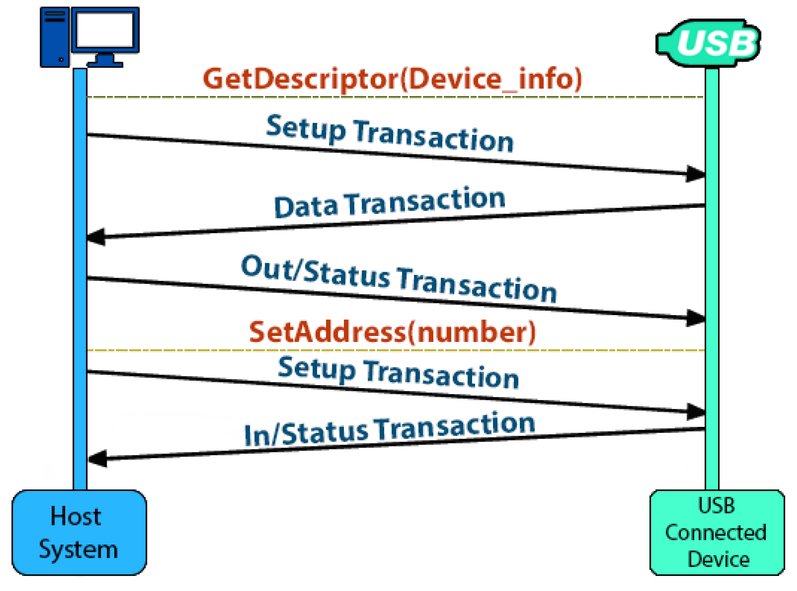
2. Background Information
3. Related Work
4. Methodology and Analysis
- ○
- Information: Displays the non-critical information.
- ○
- Warning: Provides forewarning of potential problems and not actual errors. A warning indicates that a component or application is not in an ideal state and that some further actions could yield a critical error.
- ○
- Verbose: Displays progress or success messages
- ○
- Critical: Displays the information that requires immediate attention of the system administrator. They can also be used to indicate that an application or system has failed or stopped responding.
- ○
- Error: Displays events that indicate problems, but immediate action is not required.
- ○
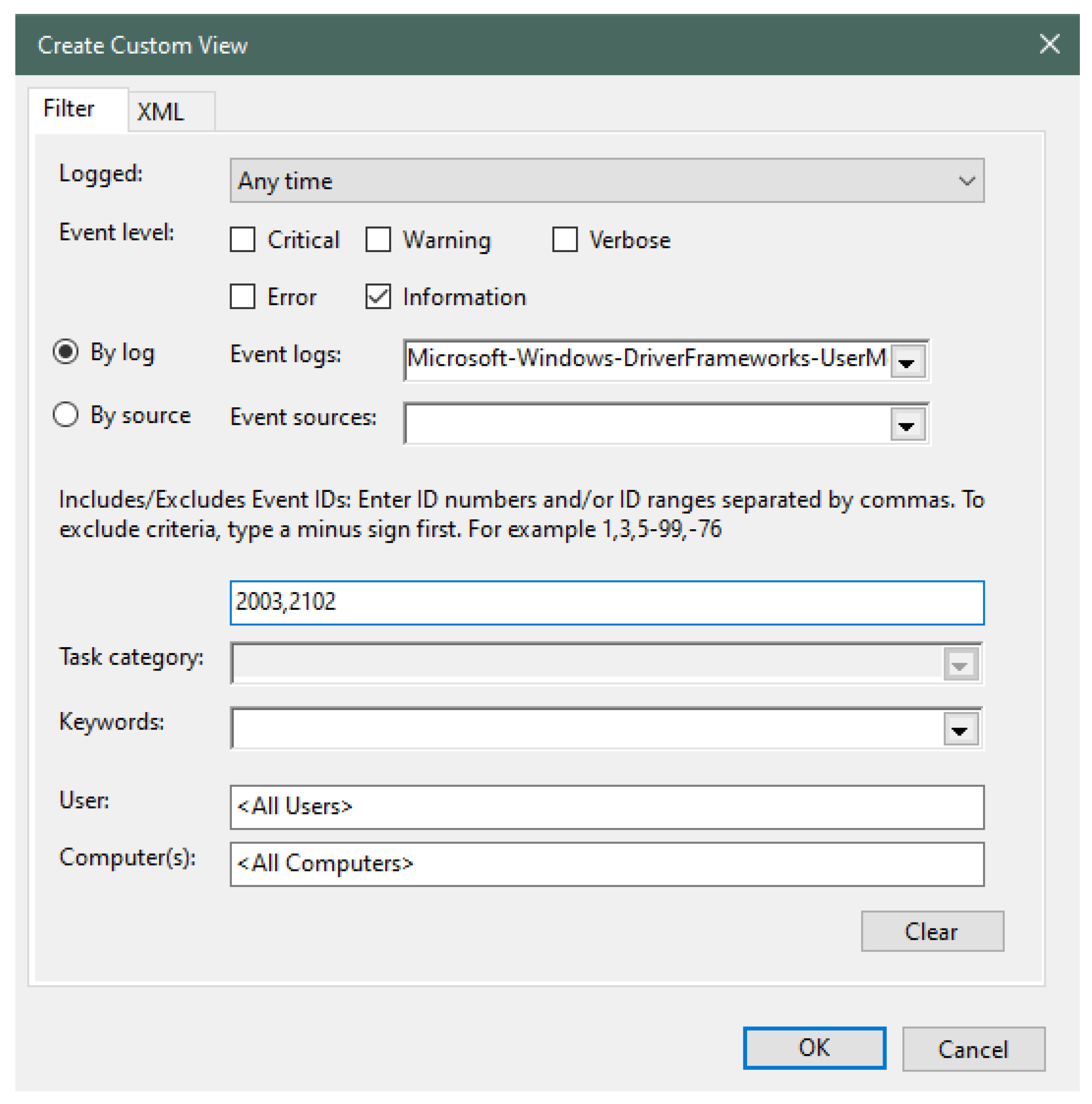
- –Connection
- ○
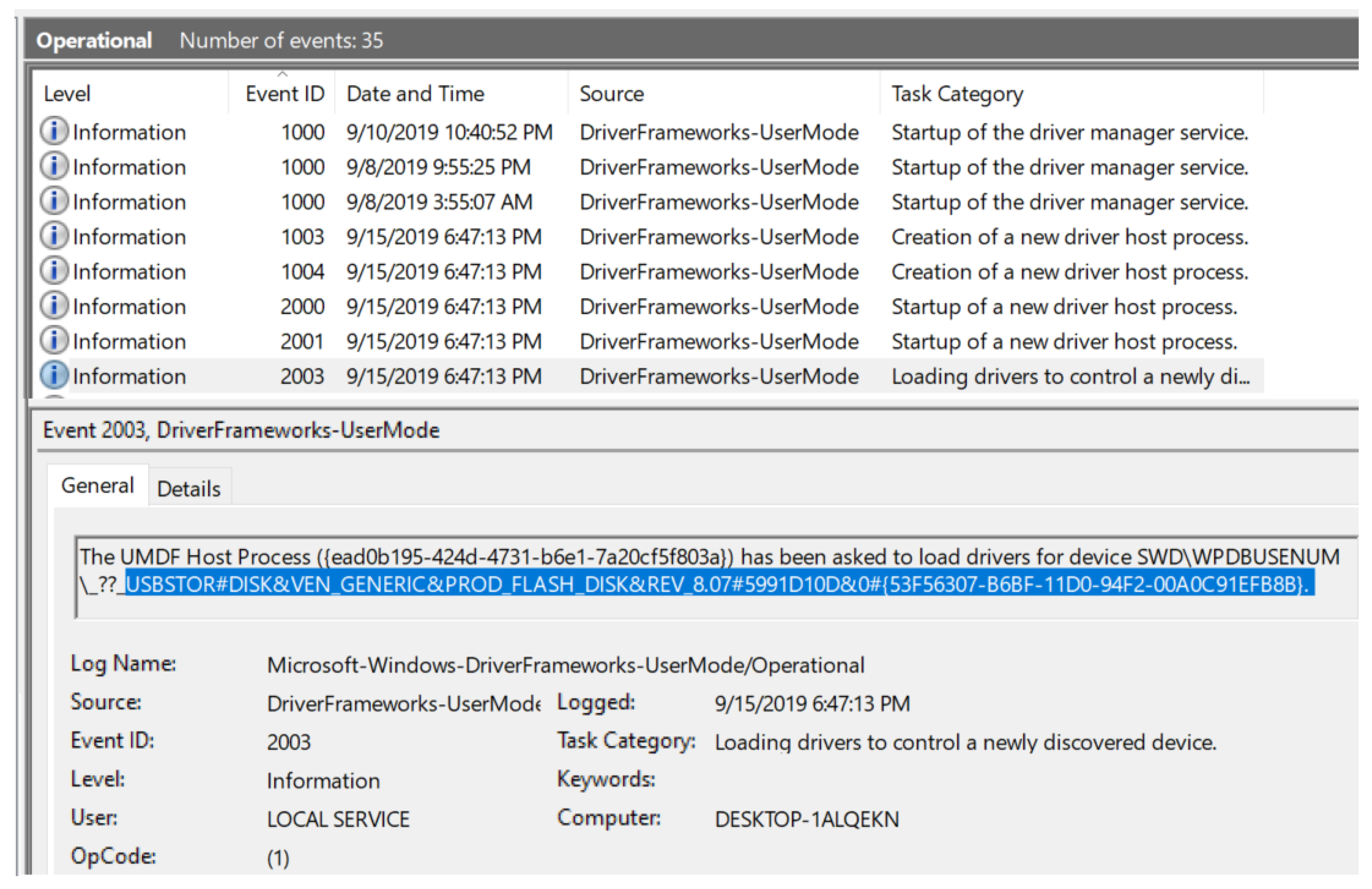
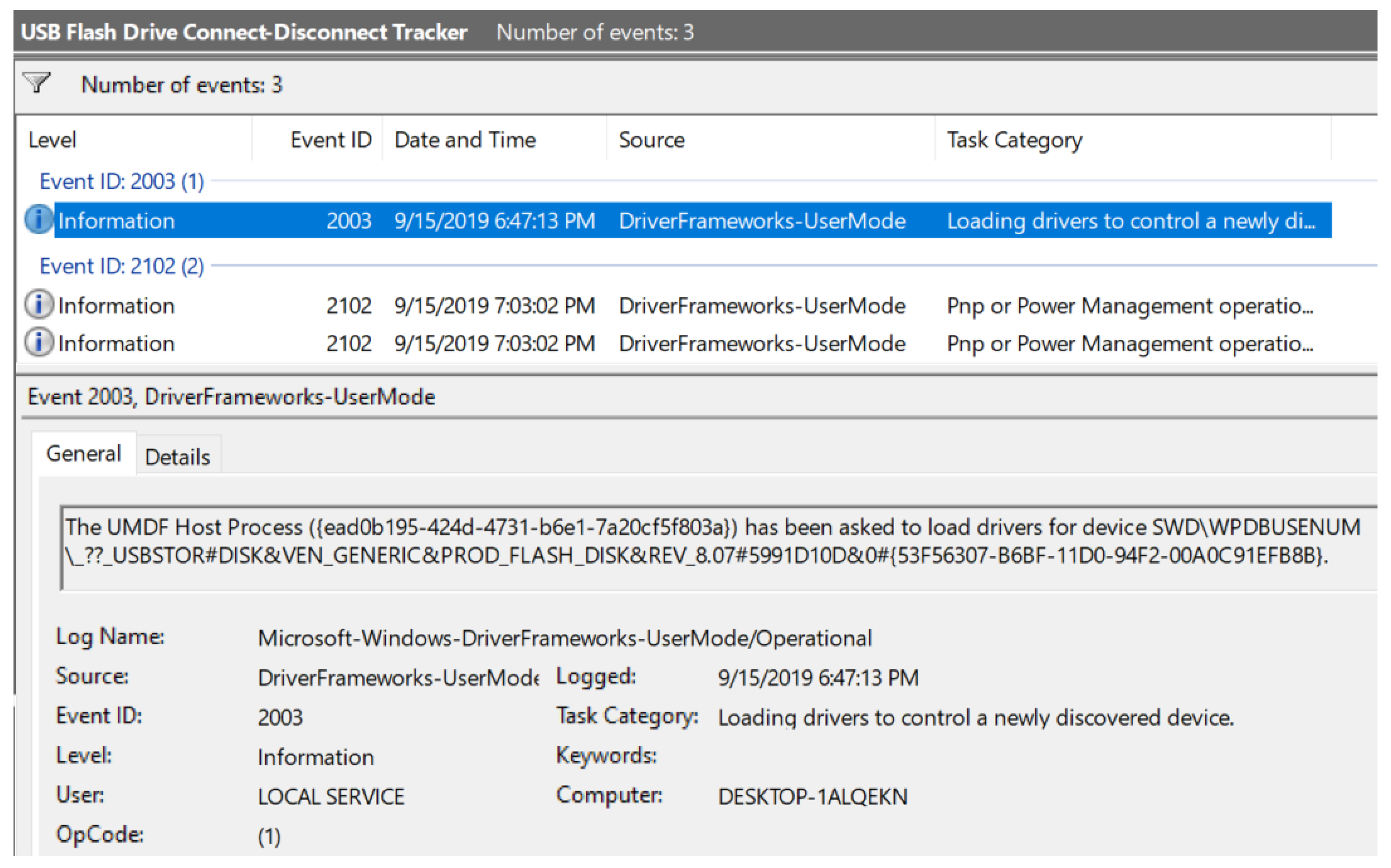
- 2003
- ○
- 2004
- ○
- 2006
- ○
- 2010
- ○
- 2101
- ○
- 2105
- ○
- 2106
- ○
- –Disconnection
- ○
- 2100
- ○
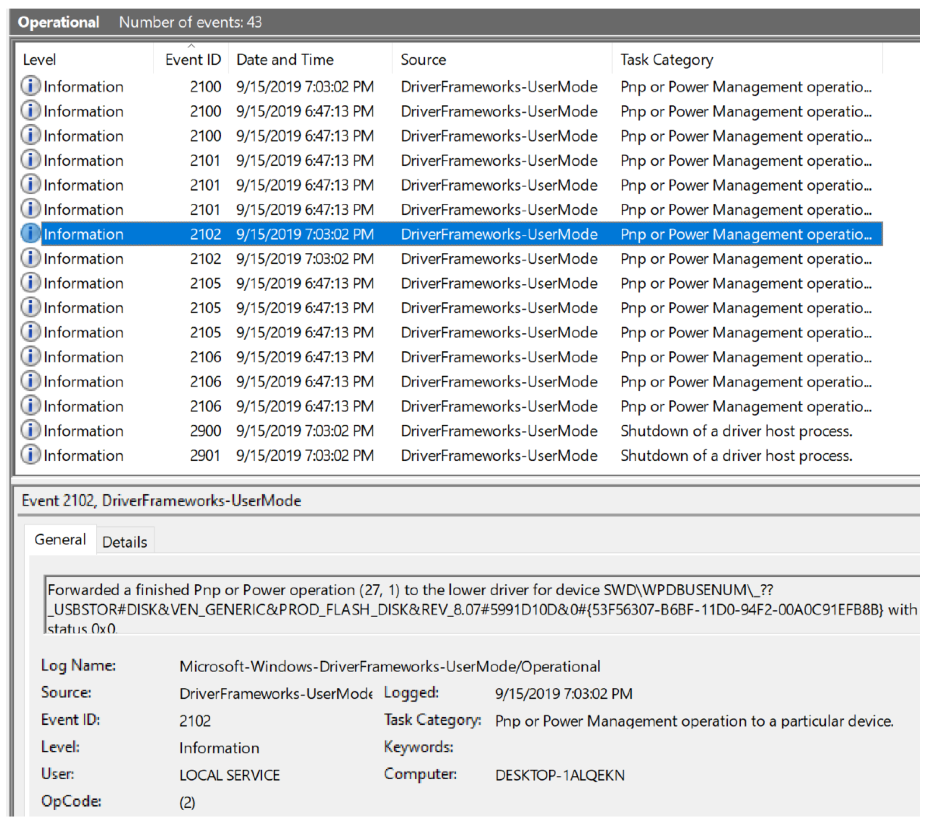
- 2102
- a.
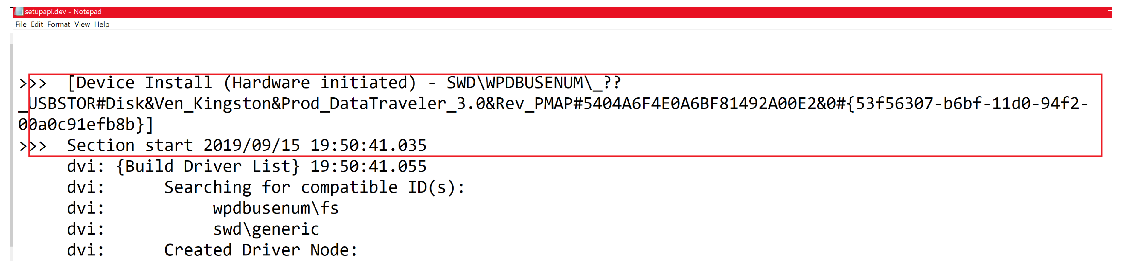
- When the vendor is generic:
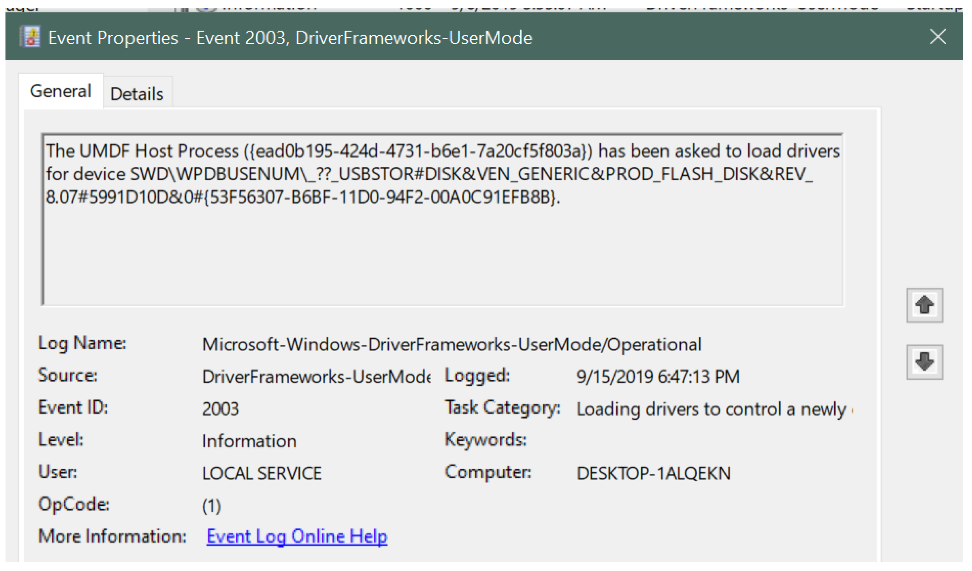
- Event ID: 2003 (for device connection)
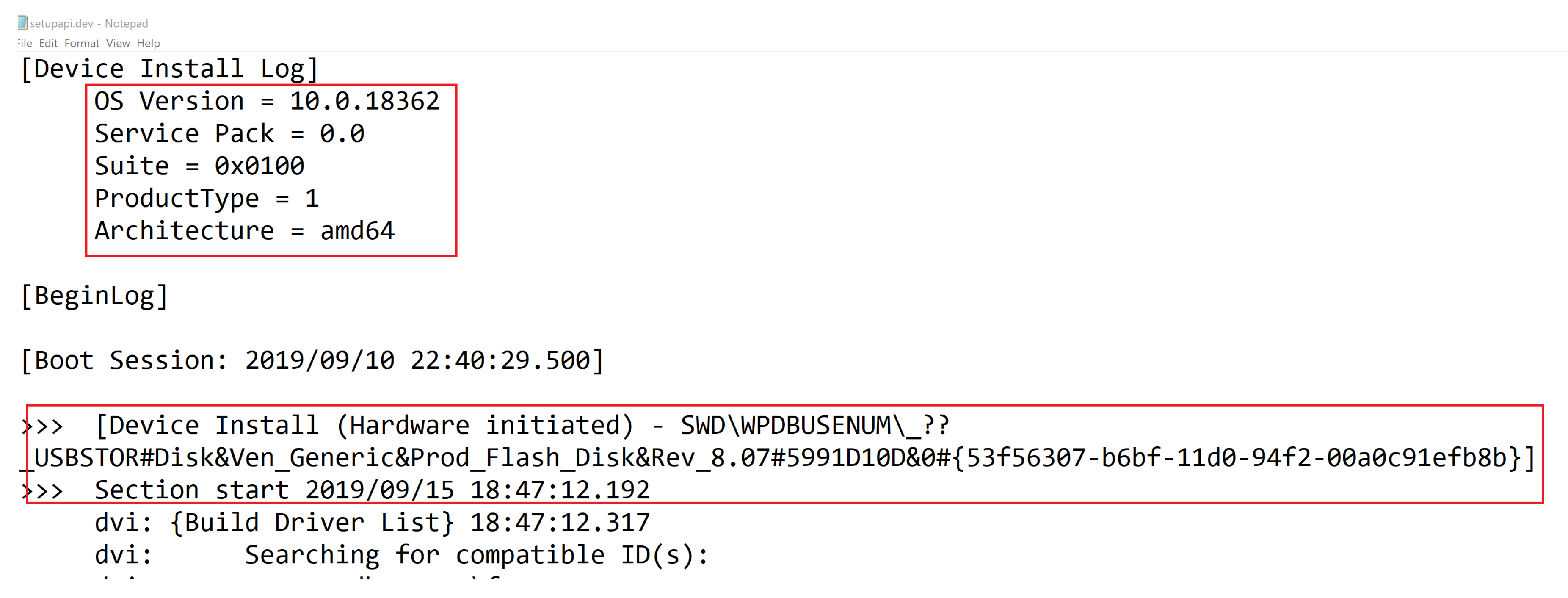
- USB type: USB flash drive indicated by USBSTOR#DISK
- Vendor name: Generic (as shown) indicated by VEN_GENERIC, upon further investigation on devicehunt.com, vendor was found to be Alcor Micro Corp.
- Product type: Flash Disk indicated by PROD_FLASH_DISK
- Serial number: 5991D10D
- Connection timestamp: 15 September 2019 at 6:47:13 PM
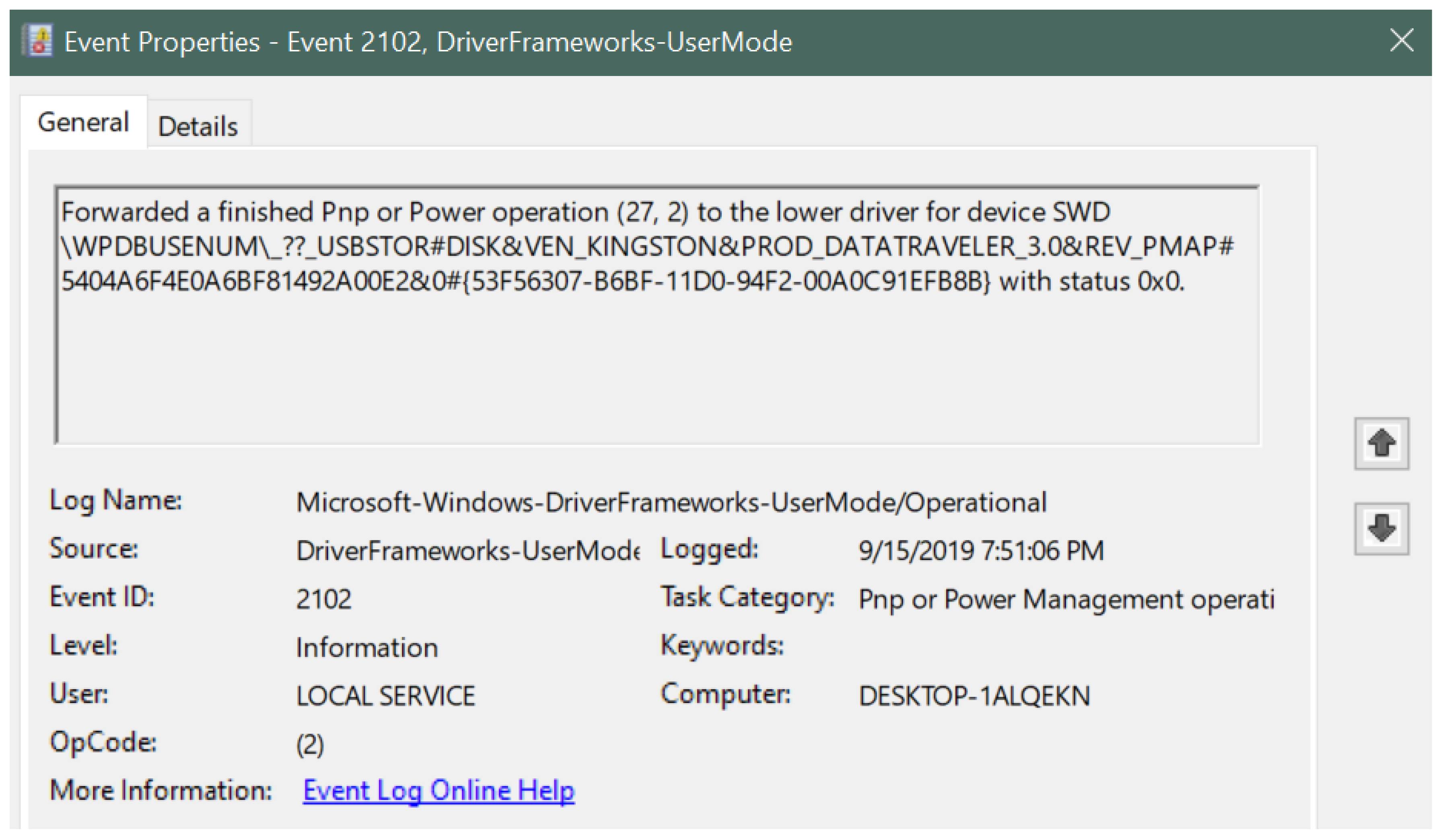
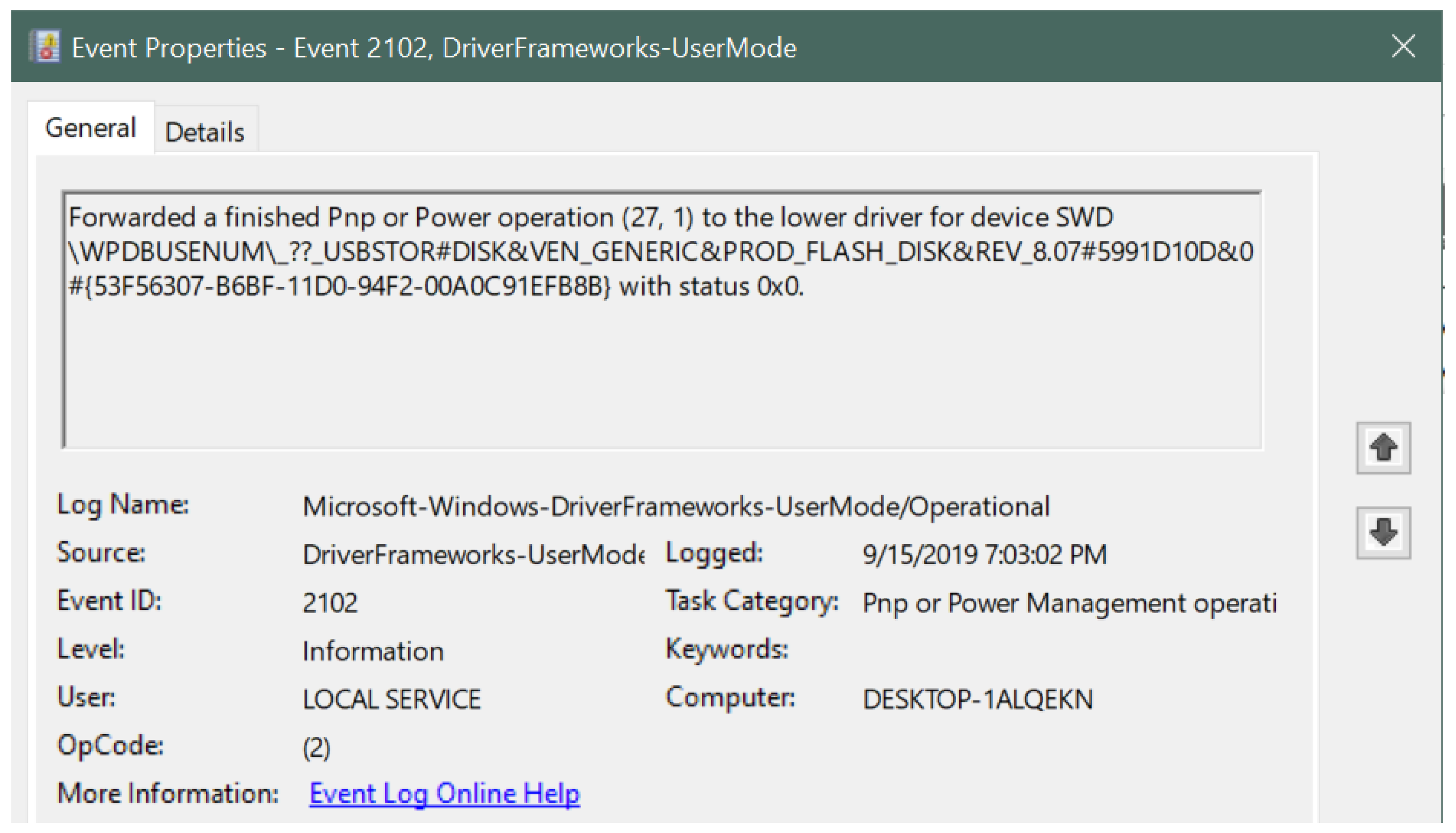
- Event ID: 2102 (for device disconnection)
- Disconnection timestamp: 15 September 2019 at 7:03:02 PM
- Disconnection status code: 0x0
- b.
- When the vendor is specific: (exact vendor and product names were mentioned in the event viewer)
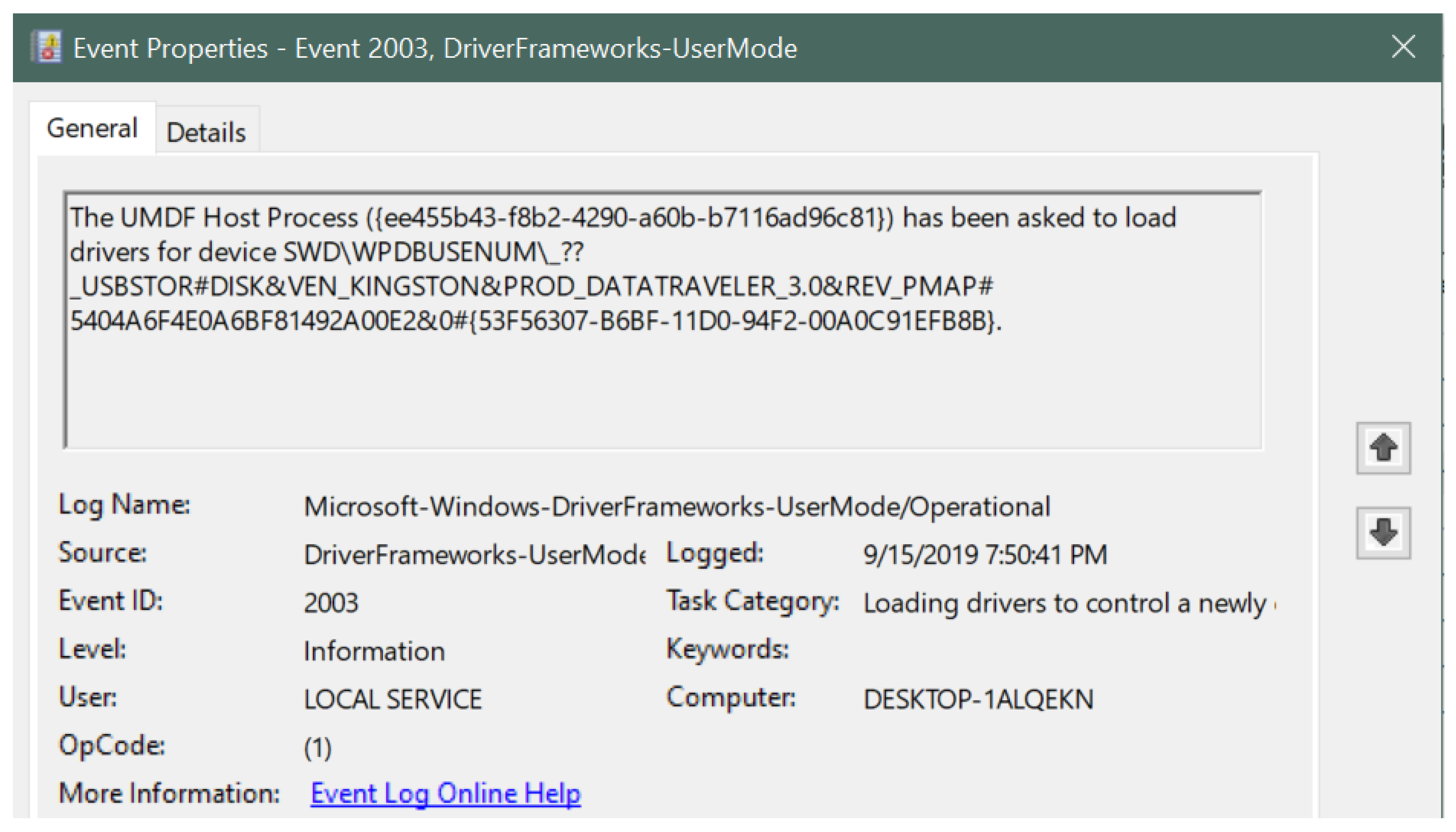
- Event ID: 2003 (for device connection)
- USB type: USB flash drive indicated by USBSTOR#DISK
- Vendor name: Kingston indicated by VEN_KINGSTON
- Product type: Data Traveler 3.0 indicated by PROD_DATATRAVELER_3.0
- Serial number: 5404A6F4E0A6BF81492A00E2
- Connection timestamp: 15 September 2019 at 7:50:41 PM
- Event ID: 2102 (for device disconnection)
- Disconnection timestamp: 15 September 2019 at 7:51:06 PM
- Disconnection status code: 0x0
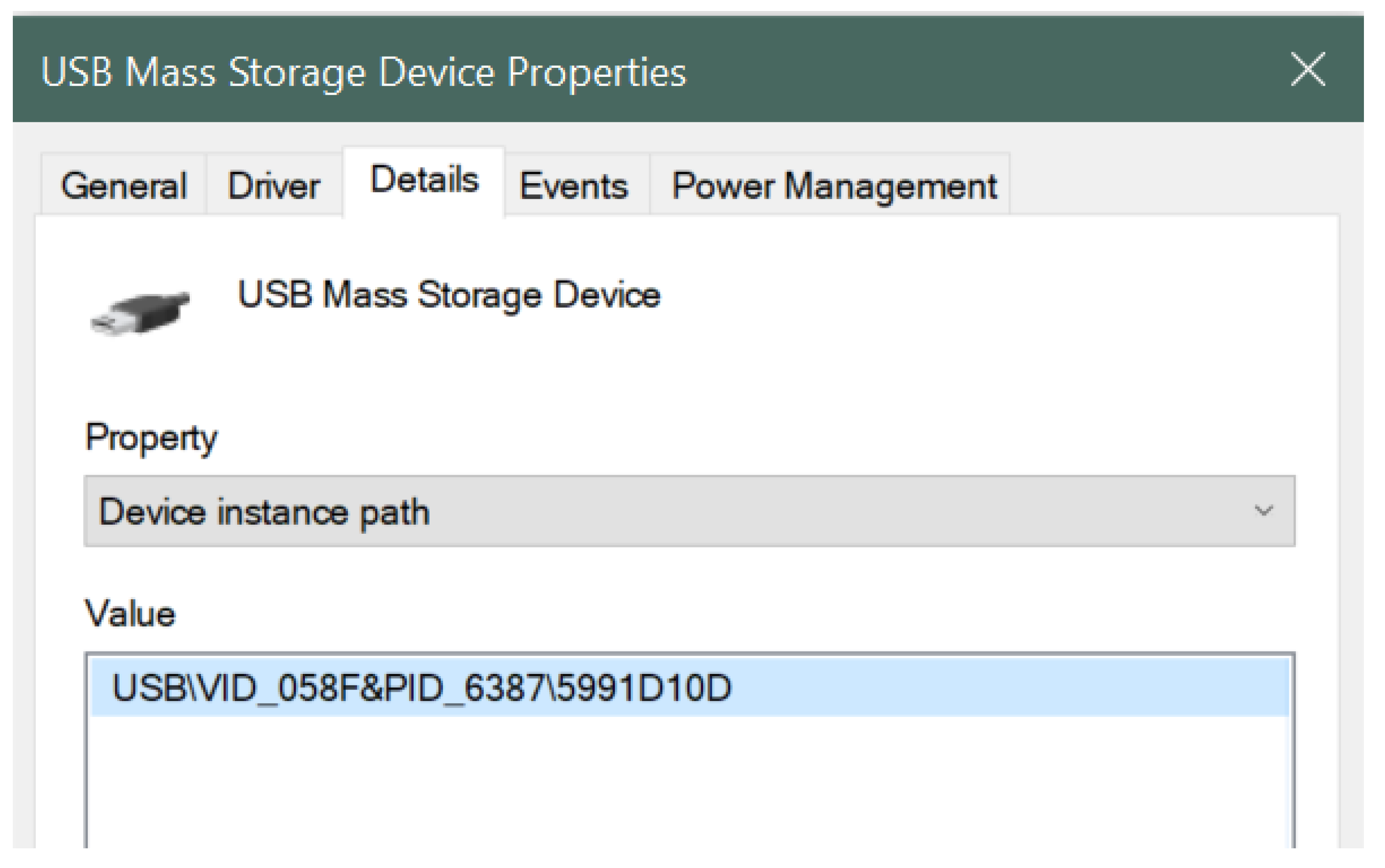
- The Device Manager was opened by going to the Windows Control Panel while a USB device was still connected to the system.
- The appropriate device was selected, in this case USB Mass Storage Device under the Universal Serial Bus Controller.
- Then, the USB Mass Storage Device was right-clicked to select the Properties.
- Lastly, the Device Instance Path was selected from the Details tab of the USB device.
- -Generic USB Flash information:
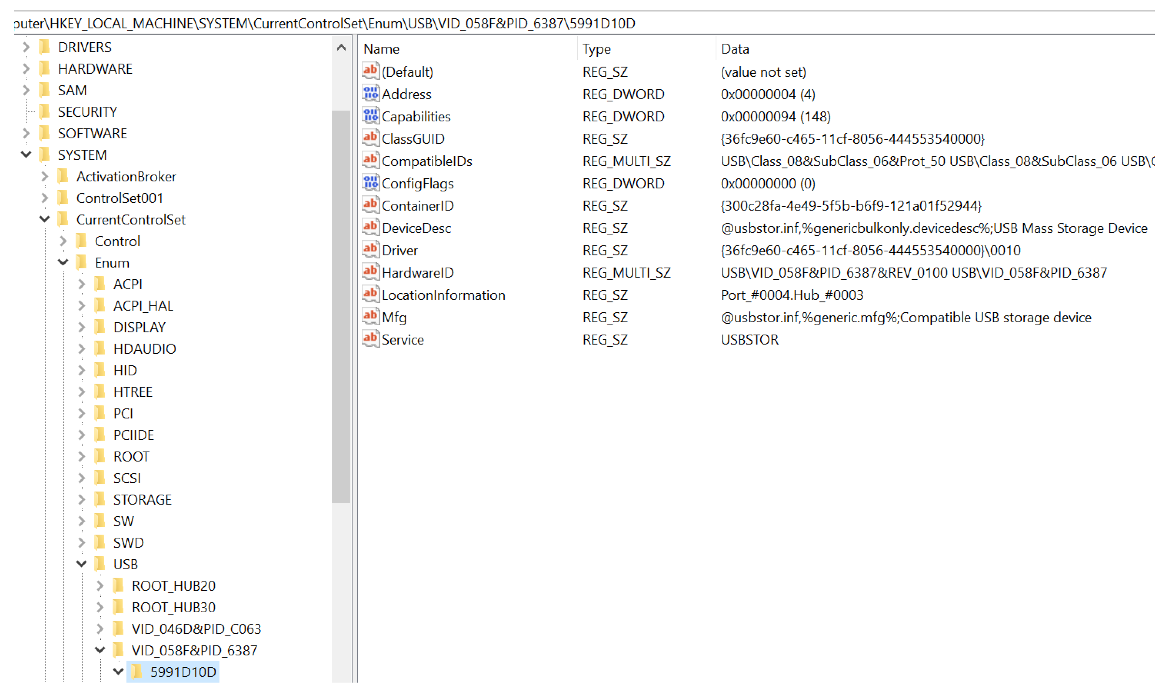
- VID (Vendor ID): 058F
- PID (Product ID): 6387
- Serial Number: 5991D10D
- -Kingston USB Flash information:
- VID (Vendor ID): 0951
- PID (Product ID): 1666
- Serial Number: 5404A6F4E0A6BF81492A00E2
- ○
- HKEY_CLASSES_ROOT
- ○
- HKEY_CURRENT_USER
- ○
- HKEY_LOCAL_MACHINE
- ○
- HKEY_USERS
- ○
- HKEY_CURRENT_CONFIG
- DeviceDesc: Information about the devise description. The value contains USB Mass Storage Device, indicating that it was a USB flash drive.
- Driver: The driver information that was used in installing the USB device.
- HardwareID: This contains the hardware signature values such as vendor ID and product ID.
- LocationInformation: This value displays the port and hub number to which the USB device was attached to on the system. In the figure, the USB device was attached to Port 4, Hub3.
- Mfg: This displays the name of Setup Information File or the INF file, which in this case was usbstor.inf, and status of the compatibility of USB device, which was Compatible USB storage device.
- Service: Display the service name associated with this registry case. In this case, the service name was USBSTOR.
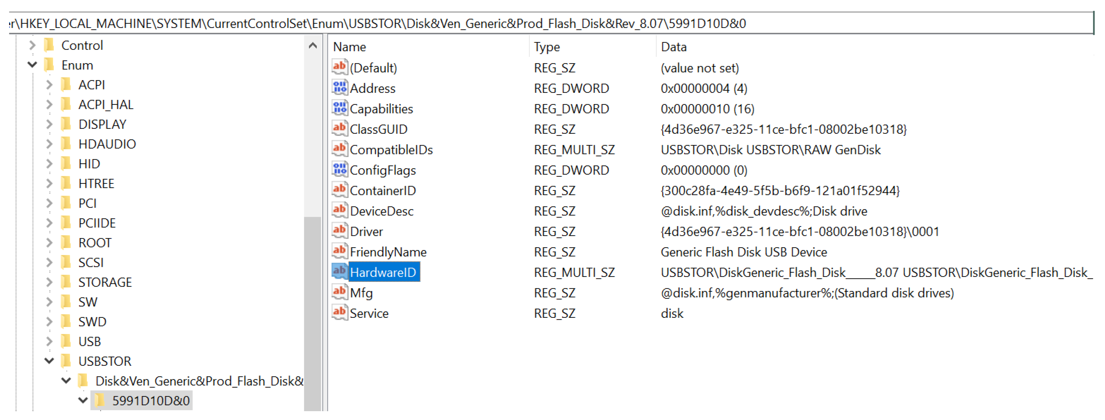
- DeviceDesc: Information about the devise description. The value contains disk drive, indicating that it was a USB flash drive.
- FriendlyName: The device name for the device. In this case, it was Generic Flash Disk USB Drive.
- Mfg: This displays the name of Setup Information File or the INF file, which, in this case was disk.inf, and the type of USB device, which was Standard disk drives.
- Service: This displays the service name associated with this registry case. In this case, the service name was disk.
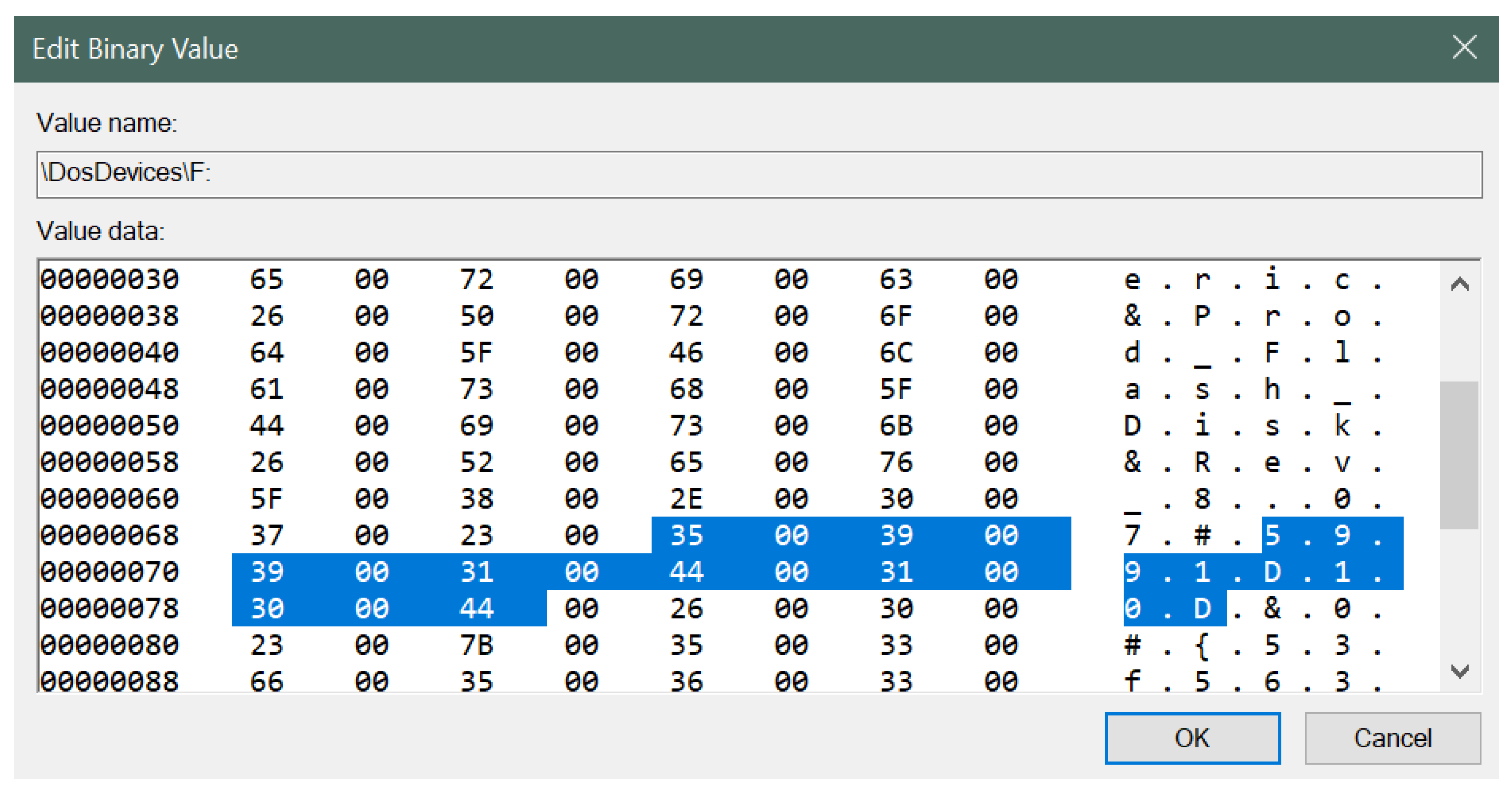
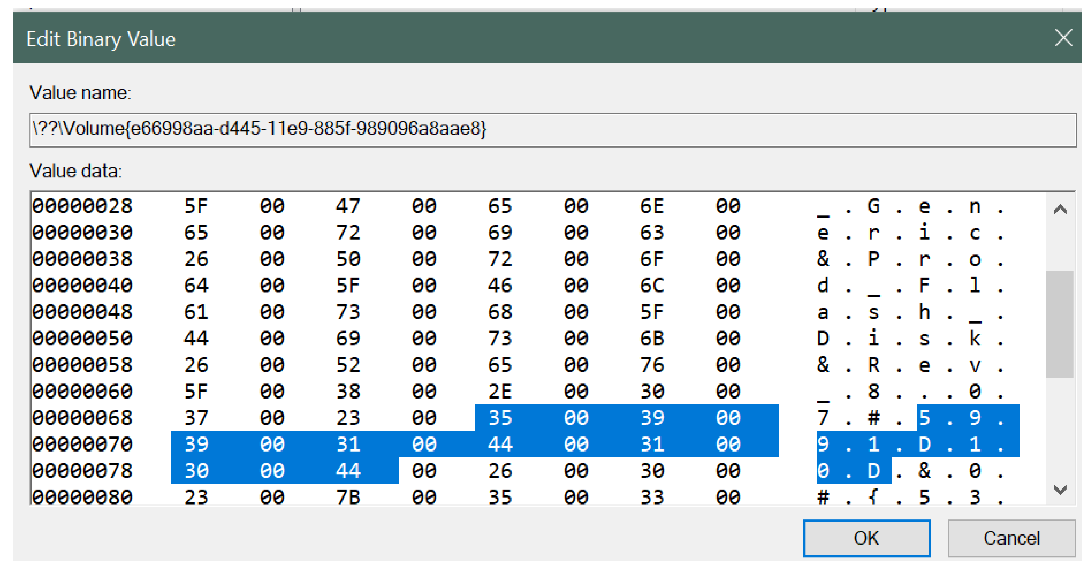
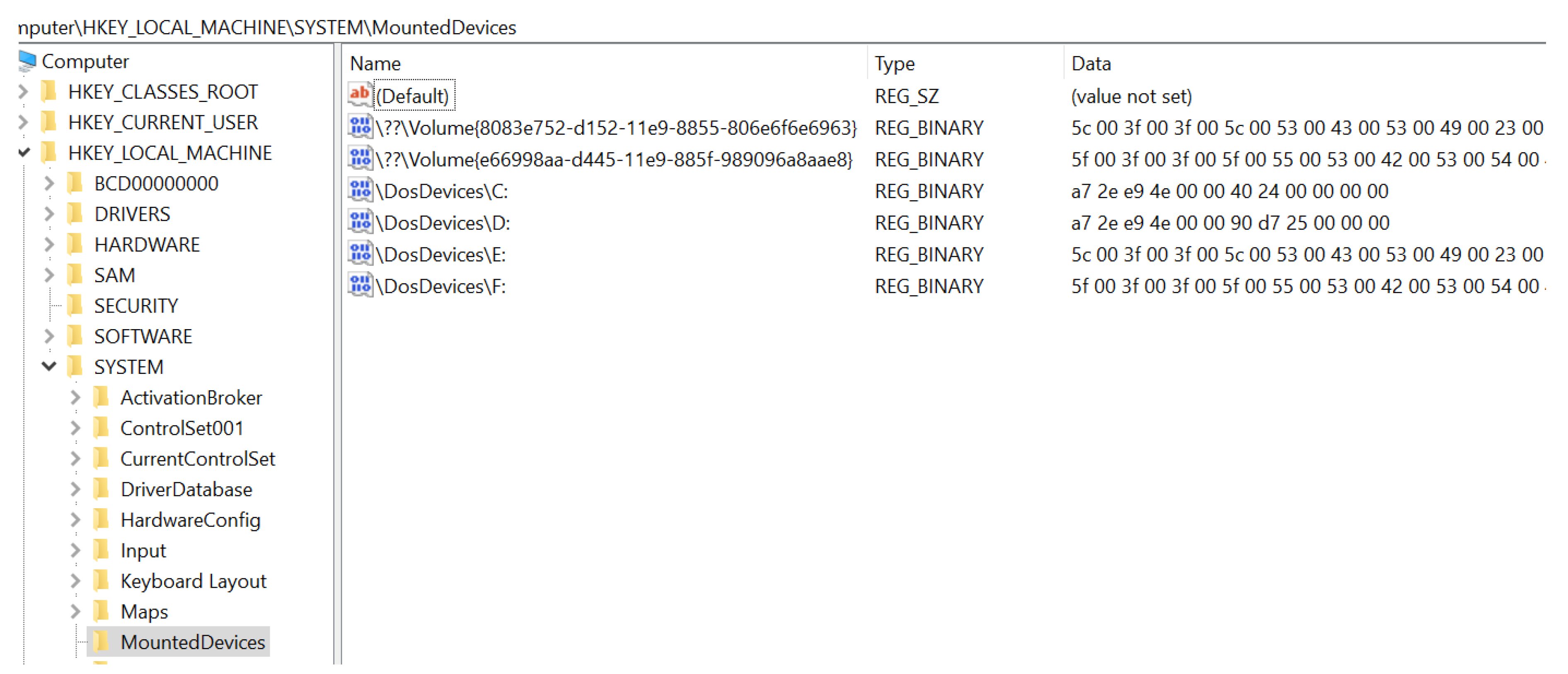
- GUID: 8bc1b2bf-4902-11e9-9f78-b8763fe48ac0
- USB Type: USB flash drive indicated by USBSTOR#DISK
- Vendor name: Generic
- Product type: Flash Disk
- Serial number: 5991D10D
- Drive Letter: F:
5. Conclusions and Future Work
Author Contributions
Funding
Conflicts of Interest
References
- Carvey, H.; Altheide, C. Tracking USB storage: Analysis of windows artifacts generated by USB storage devices. Digit. Investig. 2005, 2, 94–100. [Google Scholar] [CrossRef]
- Pham, D.V.; Syed, A.; Mohammad, A.; Halgamuge, M.N. Threat analysis of portable hack tools from USB storage devices and protection solutions. In Proceedings of the 2010 International Conference on Information and Emerging Technologies, Karachi, Pakistan, 14–16 June 2010; pp. 1–5. [Google Scholar]
- Universal Serial Bus Specification. Available online: http:sdphca.ucsd.edulab_equip_manualsusb_20.pdf (accessed on 7 August 2019).
- Bates, A.; Leonard, R.; Pruse, H.; Lowd, D.; Butler, K.R. Leveraging USB to Establish Host Identity Using Commodity Devices. In Proceedings of the NDSS, San Diego, CA, USA, 23–26 February 2014. [Google Scholar]
- Schumilo, S.; Spenneberg, R.; Schwartke, H. Don’t trust your USB! How to find bugs in USB device drivers. In Proceedings of the Blackhat Europe, Amsterdam, The Netherlands, 14–17 October 2014. [Google Scholar]
- Tian, D.J.; Bates, A.; Butler, K. Defending against malicious USB firmware with GoodUSB. In Proceedings of the 31st Annual Computer Security Applications Conference, Los Angeles, CA, USA, 7–11 December 2015; pp. 261–270. [Google Scholar]
- Wang, Z.; Stavrou, A. Exploiting smart-phone usb connectivity for fun and profit. In Proceedings of the 26th Annual Computer Security Applications Conference, Austin, TX, USA, 6–10 December 2010; pp. 357–366. [Google Scholar]
- Davis, A. Revealing embedded fingerprints: Deriving intelligence from USB stack interactions. In Proceedings of the Blackhat, Las Vegas, NV, USA, 27 July–1 August 2013. [Google Scholar]
- Letaw, L.; Pletcher, J.; Butler, K. Host identification via usb fingerprinting. In Proceedings of the 2011 Sixth IEEE International Workshop on Systematic Approaches to Digital Forensic Engineering, Oakland, CA, USA, 26 May 2011; pp. 1–9. [Google Scholar]
- Butler, K.R.; McLaughlin, S.E.; McDaniel, P.D. Kells: A protection framework for portable data. In Proceedings of the 26th Annual Computer Security Applications Conference, Austin, TX, USA, 6–10 December 2010; pp. 231–240. [Google Scholar]
- Parno, B. Bootstrapping Trust in a “Trusted” Platform. In Proceedings of the HotSec, Berkeley, CA, USA, 29 July 2008. [Google Scholar]
- Angel, S.; Wahby, R.S.; Howald, M.; Leners, J.B.; Spilo, M.; Sun, Z.; Blumberg, A.J.; Walfish, M. Defending against malicious peripherals with Cinch. In Proceedings of the 25th USENIX Security Symposium (USENIX Security 16), Austin, TX, USA, 10–12 August 2016; pp. 397–414. [Google Scholar]
- Microsoft Document. Trace and Event Log Severity Levels. Available online: https://docs.microsoft.com/en-us/previous-versions/office/developer/sharepoint-2010/ff604025(v%3Doffice.14) (accessed on 7 August 2019).
- Shultz, G. How to Track down USB Flash Drive Usage with Windows 10’s Event Viewer. Available online: https://www.techrepublic.com/article/how-to-track-down-usb-flash-drive-usage-in-windows-10s-event-viewer (accessed on 7 August 2019).
- Fisher, T. What Is Device Manager. Available online: https://www.lifewire.com/device-manager-2625860 (accessed on 7 August 2019).
- Microsoft Document. Structure of the Registry. Available online: https://docs.microsoft.com/en-us/windows/win32/sysinfo/structure-of-the-registry (accessed on 7 August 2019).


| Figures | Description |
|---|---|
| Figure 3 | This figure displays overall view of the Operational log with many event IDs along with ID 2003, which corresponds to USB device connection to the computer system. |
| Figure 4 | This figure describes the information related to the Generic USB drive corresponding to event ID 2003 in the Windows Event Viewer. The figure clearly shows the USB device signature along with the log-in time, event ID number, log name, log level, category and the computer name. |
| Figure 5 | This figure describes the information related to the Kingston USB drive corresponding to event ID 2003 in the Windows Event Viewer. The figure displays the USB device signature along with the log-in time, event ID number, log name, log level, category and the computer name. |
| Figure 6 | This figure displays overall view of the Operational log with many event IDs along with ID 2102 which corresponds to USB device disconnection from the computer system. |
| Figure 7 | This figure describes the information related to the Generic USB drive corresponding to event ID 2102 in the Windows Event Viewer. Similar to Figure 3, it shows the USB device signature along with the log-out time, event ID number, log name, log level, category and the computer name. |
| Figure 8 | This figure describes the information related to the Kingston USB drive corresponding to event ID 2102 in the Windows Event Viewer. The figure displays the USB device signature along with the log-out time, event ID number, log name, log level, category and the computer name. |
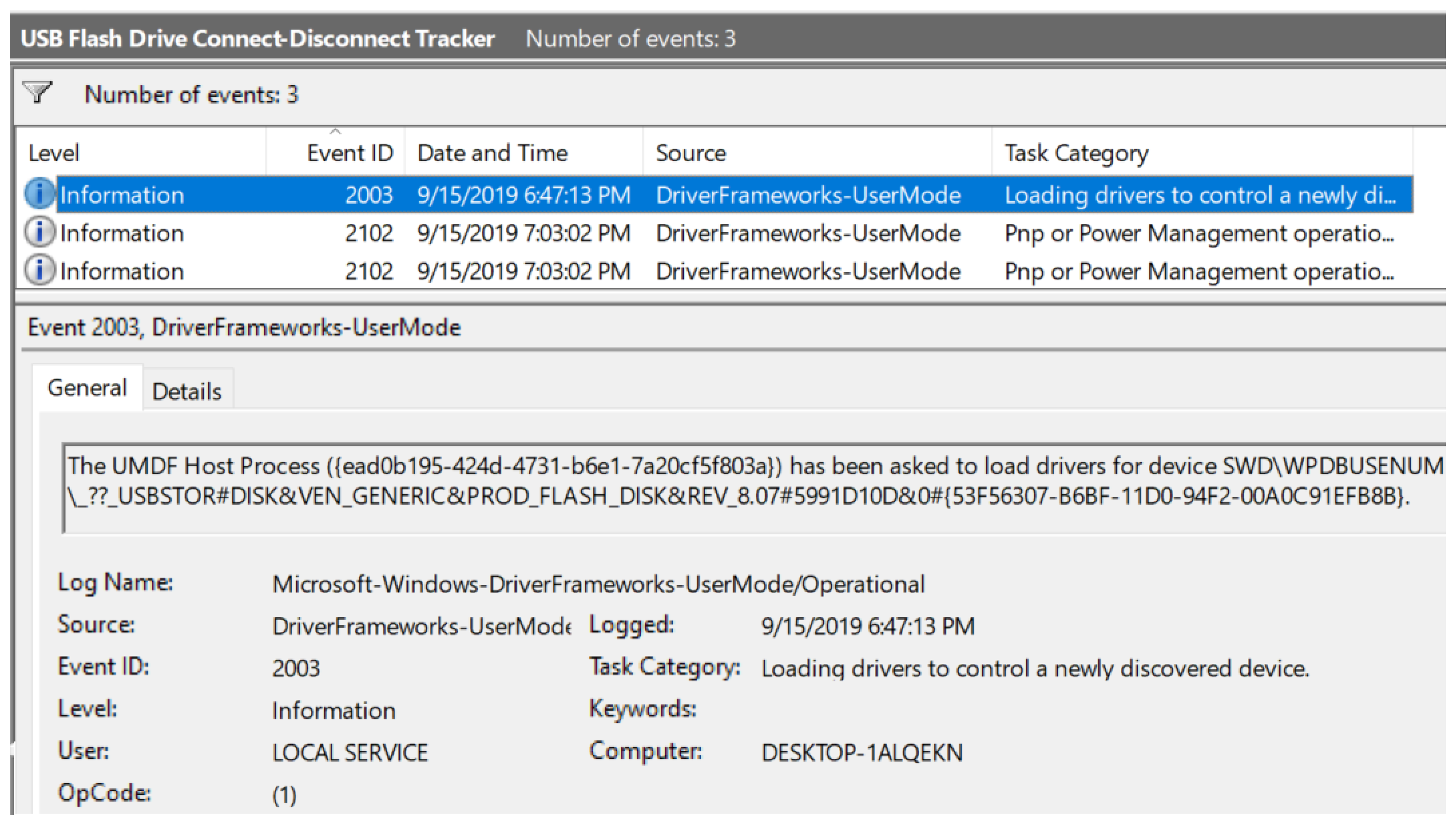
| Figure 9 | The figure describes steps involved in the Create Custom View window of Windows Event Viewer. |
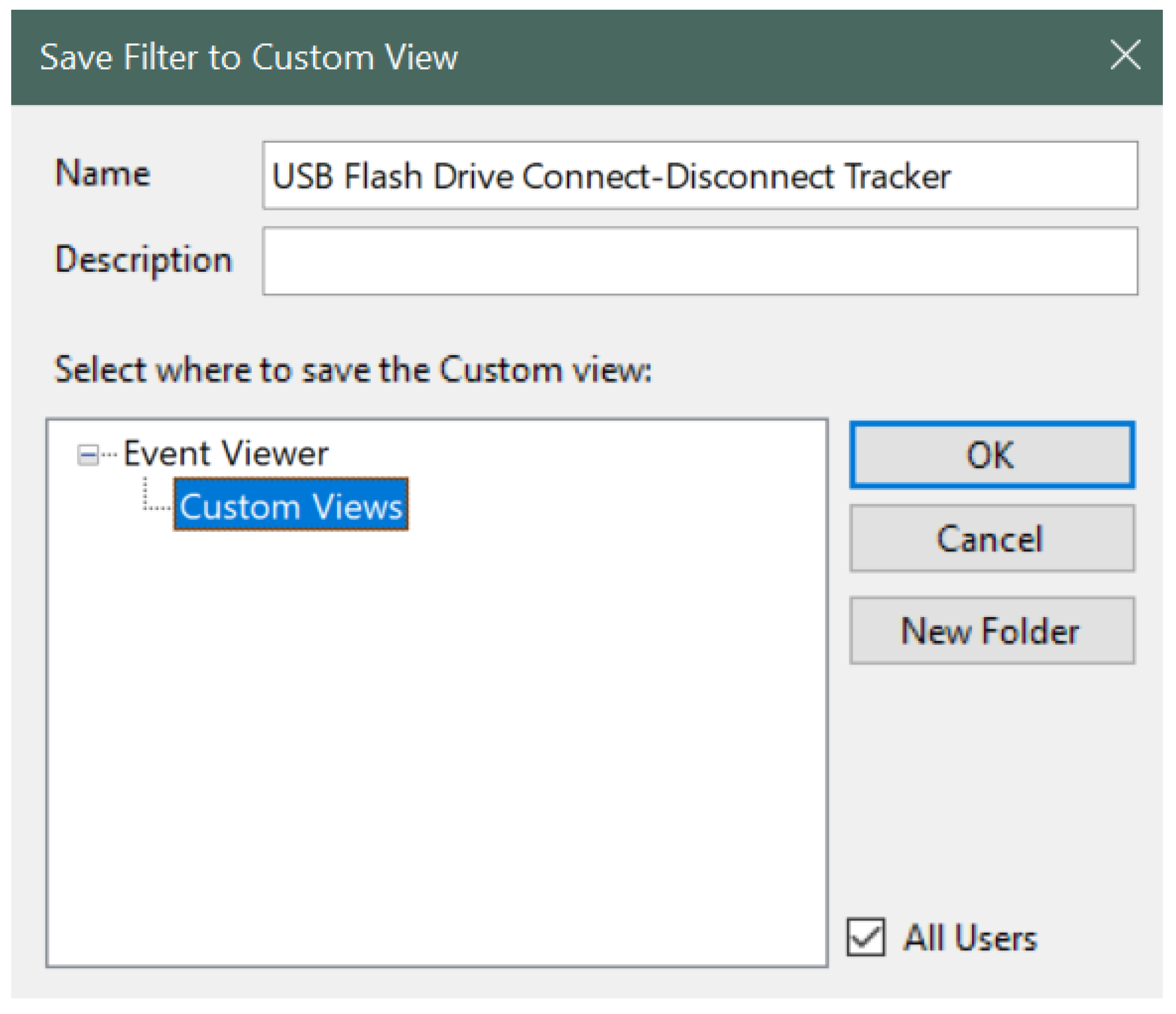
| Figure 10 | This figure displays the naming of the custom view filter. In our work, we named it as USB Flash Drive Connect-Disconnect Tracker. |
| Figure 11 | The figure displays the custom view sorted by event ID. |
| Figure 12 | The figure displays the custom view grouped by event ID for better readability. |
© 2019 by the authors. Licensee MDPI, Basel, Switzerland. This article is an open access article distributed under the terms and conditions of the Creative Commons Attribution (CC BY) license (http://creativecommons.org/licenses/by/4.0/).
Share and Cite
Neyaz, A.; Shashidhar, N. USB Artifact Analysis Using Windows Event Viewer, Registry and File System Logs. Electronics 2019, 8, 1322. https://doi.org/10.3390/electronics8111322
Neyaz A, Shashidhar N. USB Artifact Analysis Using Windows Event Viewer, Registry and File System Logs. Electronics. 2019; 8(11):1322. https://doi.org/10.3390/electronics8111322
Chicago/Turabian StyleNeyaz, Ashar, and Narasimha Shashidhar. 2019. "USB Artifact Analysis Using Windows Event Viewer, Registry and File System Logs" Electronics 8, no. 11: 1322. https://doi.org/10.3390/electronics8111322
APA StyleNeyaz, A., & Shashidhar, N. (2019). USB Artifact Analysis Using Windows Event Viewer, Registry and File System Logs. Electronics, 8(11), 1322. https://doi.org/10.3390/electronics8111322