1. Introduction
Through-the-wall radar is a technique to localize targets hidden by walls in a building’s interior [
1,
2,
3]. Important operations are in the field of security, military applications, such as counterterrorism or civil investigations, such as rescue, disaster, and fire succor. This radar technique typically makes use of ultrawideband waveforms to achieve high resolutions through very narrow pulses. However, the highest frequencies of the spectrum have small penetration through typical walls, and part of the field undergoes multiple reflections inside the wall. An accurate electromagnetic modeling of the scattering occurring in through-wall radar applications is fundamental to enhance the understanding of the physical phenomena, also serving as a benchmark of the imaging algorithms. In the literature, the electromagnetic modeling of through-wall radar is mainly done with the finite-difference time-domain (FDTD) method, as in [
4], where an FDTD implemented for ground penetrating radar was employed [
5]. A general FDTD approach was also employed in [
6]. A specific FDTD approach for the through-wall analysis in time domain, called AFDTD, was developed in [
7]. The AFDTD is based on the classical Yee algorithm, where the volume of analysis is divided in a grid of cubic cells, and its primary application is to radar target signature analysis [
1]. Due to the large investigation domains dealt with in through-wall environments, hybrid techniques are also proposed, as in [
8,
9], where FDTD is combined with high-frequency techniques, such as ray tracing or uniform theory of diffraction. Another hybrid approach was presented in [
10], where integral equations were solved with physical optics. An asymptotic technique was employed in [
11]. A frequency-domain finite element method was also proposed in [
12]. All the techniques were developed on a numerical basis and approximated to overcome limitations of long computer times and strong memory requirement needed in large simulation environments as is typical with most through-wall applications.
In this paper, an approach for the modeling of the scattering by targets behind a wall on an analytical basis is reviewed. The technique, called cylindrical wave approach (CWA), has been developed to analytically solve the two-dimensional scattering by buried or hidden targets having a circular cross-section [
13,
14,
15,
16,
17,
18], for applications in the geophysical analysis and remote sensing of subsoil, in the microwave frequency range, and as a diagnostic at optical frequencies. Expansions into cylindrical waves are used to express the fields scattered by the targets. The interactions of the scattered fields with one or more flat interfaces, bounding a semi-infinite medium or a layered one, are solved using the concept of plane wave spectrum of a cylindrical wave. By expressing a cylindrical wave through its plane wave spectrum, reflected and transmitted cylindrical waves can be suitably derived to express all the contributions to the scattered field. In [
19,
20], the CWA formulation has been extended to deal with problems of scattering by cylinders below a dielectric layer, in case of a planewave source. In this layout, three background media are considered (i.e., an air-filled half-space, a dielectric layer, and a final half-space embedding the targets). Applications are both in the remote sensing of buried targets in the subsoil, as well as in the simulation of the through-wall environments when the final half-space is filled with air. In [
19], the CWA was presented with an iterative scheme where all the multiple reflections of the scattered fields occur inside the dielectric layers where described, through a set of multiple reflection fields. The method was implemented in a faster approach in [
20], where only two sets of scattered fields were introduced that, through the definitions of the reflection and transmission coefficients relevant to a dielectric layer [
21], included all the multiple reflections in the expressions of the scattered fields. Agreement between the two methods was also presented in [
20]. Both methods have the advantage of providing an accurate analytical tool with fast computer times in large through-wall environments. Moreover, with the non-iterative scheme in [
20], execution times were considerably reduced compared to those in [
19], as proven in an extensive comparison presented in [
20]. This comparison showed the dependence of the two methods on the simulation parameters, including as radius of the cylinder, the thickness and permittivity of the wall, and the number of cylinders. In this paper, the non-iterative approach developed in [
20] was recalled and extended to excitation from a line source. The radiated field was expanded through a zeroth-order Hankel function, and its reflection and transmission through the interfaces were dealt with by applying the same spectral approach employed for the scattered fields. As for the numerical implementation, potentialities of the CWA for the modeling in through-wall environments are presented.
This paper is organized as follows: In
Section 2, the theoretical approach, applied to a line-source excitation, is presented. In
Section 3, numerical results of through-wall simulation are reported.
2. Theoretical Approach
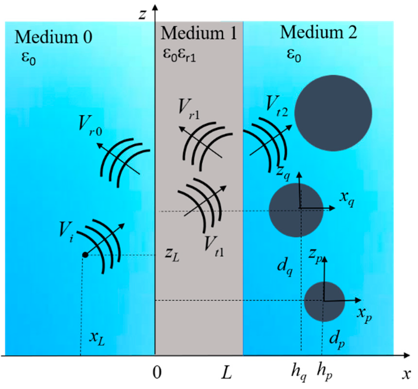
The geometry of the problem is sketched in
Figure 1. In medium 0 (air, ε
r0 = 1), the source of the scattering problem, a line source with center in (
xL,
zL), is present.
N cylinders, perfectly conducting or dielectric, are placed in an air-filled medium with relative permittivity ε
r2 = 1 (medium 2), below a dielectric layer of thickness
L and relative permittivity ε
r1 (medium 1). The model is two-dimensional, assuming the length of the targets is much longer than the size of their cross-section.
Normalized coordinates (ξ,ζ) are employed, ξ = k0x and ζ = k0z, with k0 being the vacuum wavenumber. N reference frames (ξp, ζp) centered on the axis of the p-th are also introduced, and the p-th cylinder has radius aq and center in (hq, dq), the normalized radius being αp = k0ap, and the normalized center (χp = k0hp, ηp = k0dp), with p = 1, …, N. Normalized thickness of the interface is Λ = k0L. The normalized coordinates of the center of the line source are given by (χL, ηL).
A scalar function V(ξ,ζ) is used to represent the component of the electromagnetic field parallel to the cylinders’ axis, depending on the polarization state. It is V = Ey in the TM or E polarization, and V = Hy in the TE or H polarization.
Here, the non-iterative approach is presented in the case of excitation with a line source, defined through an amplitude
V0 and proportional to the zeroth-order first-kind Hankel function
[
22]:
An alternative representation is now introduced for the cylindrical wave in Equation (1). With the position
,
CW0 is a cylindrical wave of zeroth-order that can be defined through a spectral representation:
where the plane wave spectrum
is given by:
By evaluating the reflected or transmitted plane wave on each plane wave of the spectrum (Equation (2)), the fields originated by reflection and transmission of the incident field
Vi—in the absence of the cylinders, as highlighted in
Figure 1—can be derived. The amplitudes of the plane waves are derived through reflection and transmission coefficients, with definition dealing with the interaction of a plane wave with a dielectric slab [
21], which includes all the multiple reflections by the flat boundaries. As for the propagation terms, they are derived from the parallel and orthogonal components
and
, respectively, of the normalized wavevector
through the Snell law, being
and
. In particular, the field
transmitted in the final medium can be expressed through a transmitted cylindrical function of zeroth-order:
where
and
are the orthogonal and parallel components, respectively, of a generic plane wave transmitted in medium 2.
The final expression of the field
is:
The other field contributions (Vr0, Vr1, and Vt1), relevant to reflection and transmission of the incident field by the layer can be derived in a similar manner through suitable cylindrical functions, as in Equation (4).
As the field
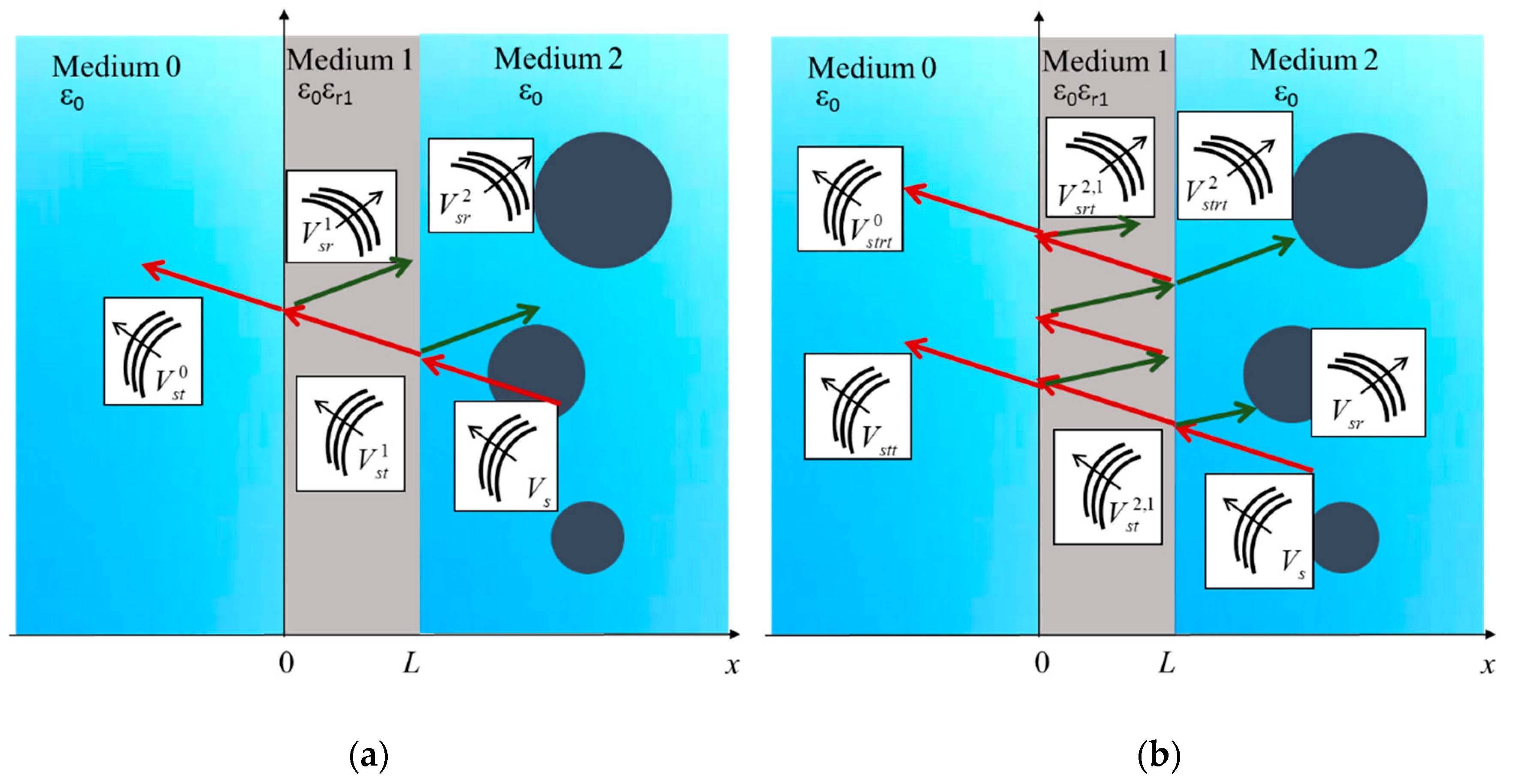
impinges on the targets in medium 2, the following scattered field contributions are excited, as depicted in
Figure 2a:
: fields scattered by the cylinders in medium 2;
: scattered-reflected field in medium 2, by the interface in ζ = Λ;
: scattered-transmitted field in medium 1, by the interface in ζ = Λ;
: scattered-reflected field in medium 1, by the interface in ζ = 0;
: scattered-reflected field in medium 0, by the interface in ζ = 0.
With the field decomposition presented above, all the multiple interactions experienced by the scattered fields inside the layer comprise two sets of waves. The first is a left-propagating wave, which from medium 2 is scattered into medium 0 and decomposed into the fields
,
, and
. The second is a right-propagating wave, which from medium 0 is scattered back in medium 2, through the fields
and
. This compact decomposition, presented in detail in [
20], leads to a faster approach to the solution of the scattering problem, compared to the one of
Figure 2b [
19]. In the latter, all the possible interactions of the scattered fields inside the boundary are taken into account, through multiple reflection fields
,
, and
. Such fields are given by infinite and convergent series, which are truncated to a finite number of terms in the numerical implementation depending on the desired accuracy.
In both approaches in [
19,
20], the scattered field
in medium 2 by the cylinders can be defined through an expansion into cylindrical functions of
m-th order:
where
is the first-kind Hankel function of order
m and
is an angular factor. Employing the basis functions in Equation (6), the scattered field by
N cylinders is given by:
where
are unknown expansion coefficients, and
and
are the Kronecker symbols.
The definition in Equation (7), obtained by applying the addition theorem of Hankel functions and the plane wave expansion of a cylindrical wave, returns an expression of the scattered fields in polar coordinates centered on the axis of the
q-th cylinder [
13]. A representation in a polar reference frame is indeed adopted for the fields propagating in medium 2, being more suitable to apply boundary conditions on cylinders’ surfaces, as is done in the following explanation.
The scattered field contributions in both approaches [
19,
20] are derived through suitable cylindrical functions from the cylindrical functions of order
m in Equation (6), expressed through its plane wave spectrum [
13]:
being:
with
and
the parallel and orthogonal component, respectively, of the normalized wavevector
. The expressions in Equations (8) and (9) generalize the ones in Equations (2) and (3), respectively, to a cylindrical wave of
m-th order. Therefore, with an approach analogous to the one employed to derive the transmitted function in Equation (4) from the incident field
Vi, it is possible to derive the cylindrical waves to be used as basis functions of the reflected and transmitted scattered fields. The further scattering contributions are presented for the decomposition of
Figure 2a. A scattered reflected field is excited by the interaction of the field
Vs with the flat boundary in
ξ =
Λ of separation between medium 1 and medium 2. It is expressed through an expansion into reflected cylindrical waves in medium 2:
In Equation (10), the reflection coefficient
at the medium 1/medium 2 boundary is the one for a dielectric slab [
21]. The cylindrical waves in Equation (10) are employed as basis functions of the scattered reflected field in medium 2:
As explained above for the scattered field in Equation (7), the definition of the scattered–reflected field in Equation (11) is expressed in a polar reference frame centered on the q-th cylinder.
As for the field contributions in medium 1, they are expressed through the transmitted cylindrical waves in medium 1:
and the reflected cylindrical waves in medium 1:
Equations (12) and (13) are used as basis functions of the scattered–transmitted and scattered–reflected field in medium 1, respectively, represented through:
and:
Finally, transmitted cylindrical waves in medium 0 are introduced:
and they are employed as basis functions of the scattered-transmitted field in air:
In the case of dielectric targets of relative permittivity
εrc, a further field contribution must be included (i.e., the scattered field transmitted inside the cylinders). Its representation is given through an expansion in first-kind Bessel functions
and a second set of unknown expansion coefficients
:
For the determination of the expansion coefficients in the scattered fields—Equations (7), (11), (14), (15), (17), and the coefficients of the field in Equation (18)—the boundary conditions relevant to the tangential fields to the cylinders’ surface are imposed. Therefore, only the field’s components propagating in medium 2 are involved and are expressed in polar coordinates as already implemented in Equations (5), (7), (11), and (18).
In TM polarization, boundary conditions are:
where in the TE polarization states it is:
with
p = 1, …,
N. In the case of PEC targets, the second member of the conditions (Equations (19) and (20)) reduces to zero. By introducing in Equations (19) and (10) the definitions of the fields in Equations (5), (7), (11), and (18), a linear system is obtained after some manipulation for the expansions coefficients
:
In Equation (21), the superscripts γ = 1,2 refer to the boundary conditions in Equations (19) and (20), respectively, and it is
,
and:
being
,
, and
,
, where
or
for TM or TE polarization, respectively.
The coefficients
relevant to the scattered field transmitted inside the cylinders are found from:
With PEC targets, the final system is the same as in Equation (21), with equal to the matrix in Equation (22), and the term corresponding to the definition in Equation (23).
3. Results
The approach presented in
Section 2 was solved numerically to model scattering applications of targets hidden behind a wall, as with the through-wall radar investigations. In the system (Equation (21)), the order
p and
of the expansions into cylindrical waves were truncated to a finite number of terms (
Mt). As a truncation rule, to give a compromise between accuracy and computational heaviness, a number of terms
[
23] were employed in numerical computations, where
α was the radius of the largest cylinder and
the refraction index of medium 1. Therefore, the size of the system (Equation (21)) was
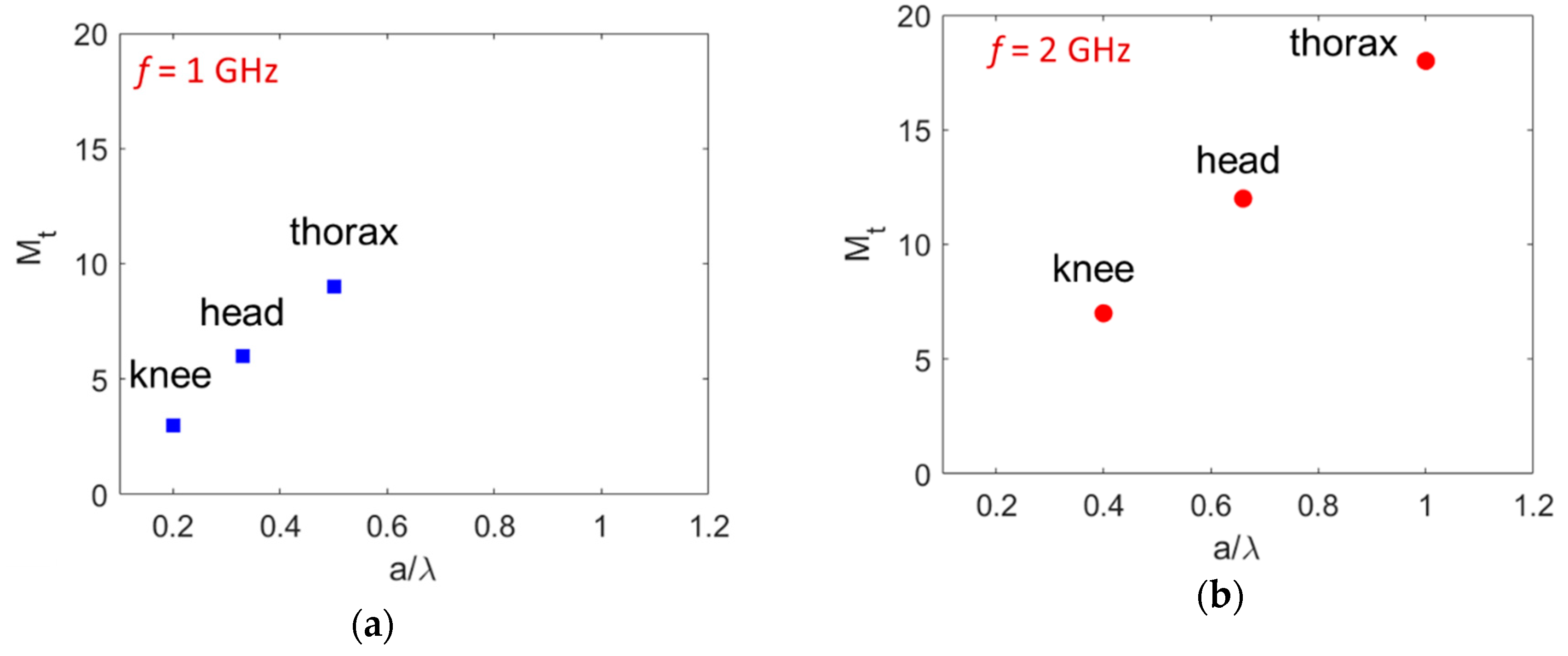
. In the modeling of human targets in the typical frequency range of through-wall radars, the truncation number
can assume high values. Possible values of
Mt are reported in the plots of
Figure 3, for different sizes of parts of the human body, including knee (radius
a = 6 cm), head (radius
a = 10 cm), and thorax (radius
a = 15 cm), evaluated at 1 GHz (
Figure 3a) and 2 GHz (
Figure 3b), with
. The truncation
Mt in this implementation of the CWA for the through-wall modeling was larger than with the geophysical analysis, as in [
18], where targets like pipes and subservices were detected at the maximum frequency of 1 GHz. Instead, in the through-wall investigations, the size of the targets was larger compared to the operational frequencies, (i.e., a larger
a/
λ ratio was employed). However, the following results confirm that the results of the CWA were stable and convergent, although a higher number of terms in the expansion of the scattered field must be included.
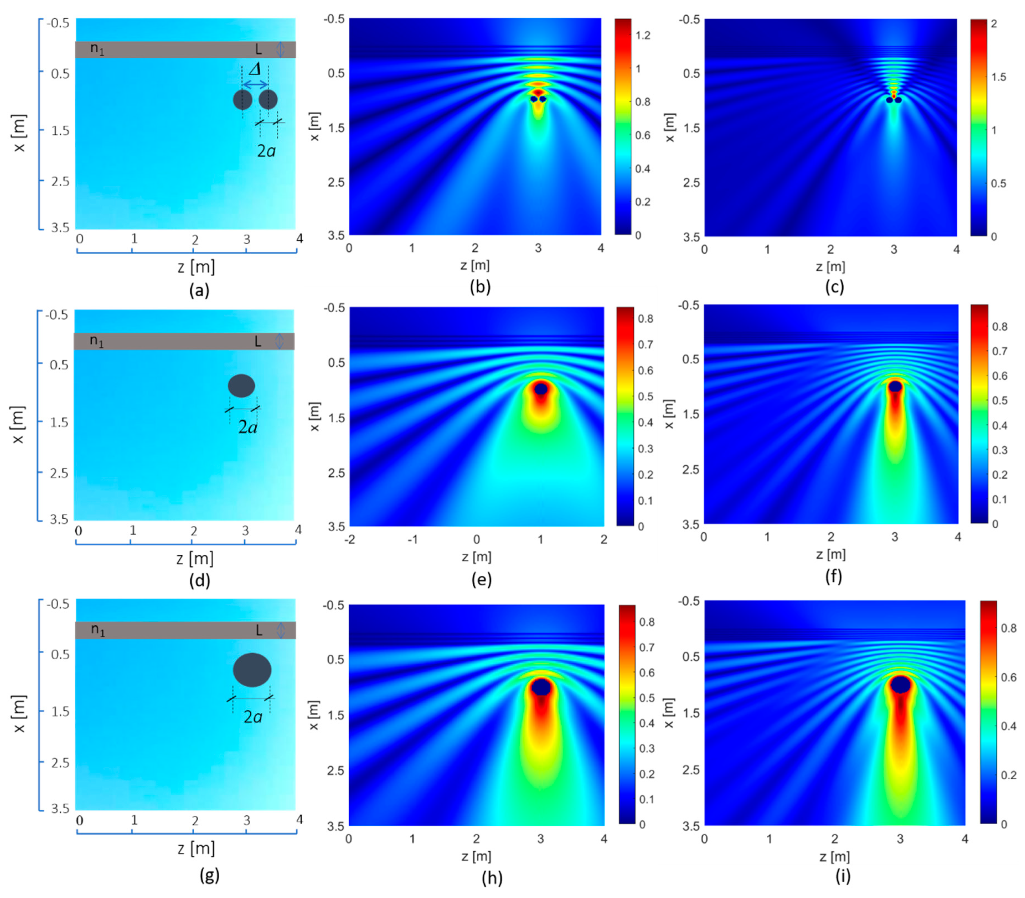
Some results showing the potentialities of the method for the simulation of through-wall layouts are now illustrated. For target modeling, in the frequency range from 1 to 2 GHz, permittivity of biological tissues was high and can be represented either as a dielectric medium or as a PEC. In the dielectric modeling, a real part of the permittivity was ε
rc = 50, and an electrical conductivity σ = 1 S/m was assigned. In
Figure 4, two-dimensional field maps are reported for the targets highlighted in
Figure 3 (i.e., two knees (plots (a–c)), head (plots (d–f)), and thorax (plots (g–i)), modeled as PEC targets under plane wave excitation (as in [
20]) in TM polarization and normal incidence. As for the wall parameters, thickness was
L = 20 and relative permittivity was ε
r1 = 4. The total scattered field was evaluated in each medium, at the frequencies of 1 GHz and 2 GHz. In
Figure 3b,c, effects of constructing interference between two interacting targets can be observed.
In the results of
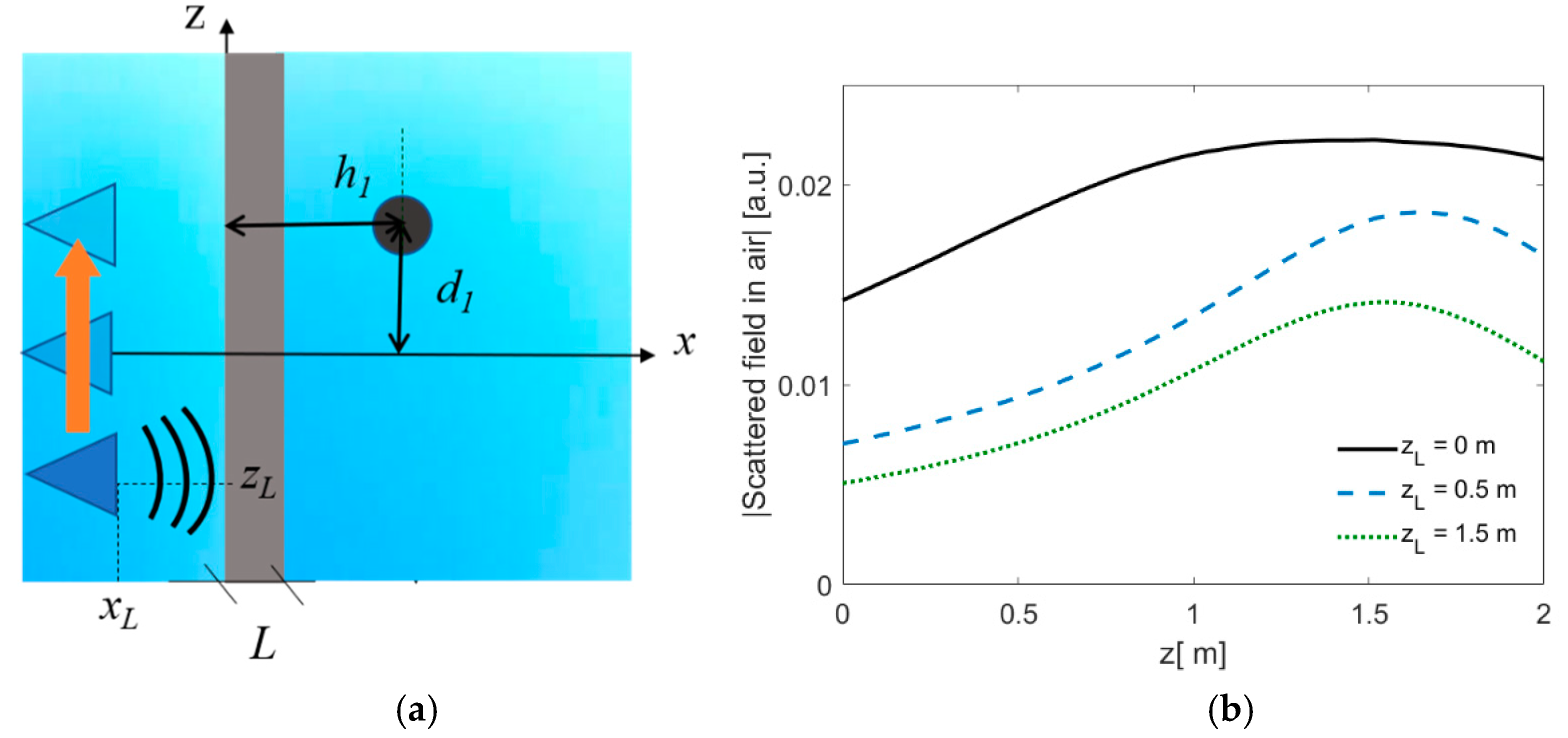
Figure 4, the use of a plane wave as incident field was equivalent to an excitation with a far-field source. The effect of excitation with a line source as in Equation (1) is shown in
Figure 5. The target was modeled as a dielectric one, with radius
a = 10 cm, and center in (
h1,
d1) = (0.6 m, 0.5 m). The center of the line source was in (x
L = −0.5 m, z
L), as the coordinate z
L was moved from −1 m to a position aligned with the cylinder axis, and the scattered field in medium 1 was collected along a line parallel to interface in x = −50 cm. The geometry of the problem is reported in
Figure 5a. The results in
Figure 5b show the reduction in amplitude for lateral positions of the source, for a wall with
L = 20 and ε
r1 = 4. This extension of the method to a line source excitation allows modeling of the multistatic acquisition employed in multifrequency approaches [
24], as explored in recent algorithms for the imaging of targets in a through-wall environment [
25].
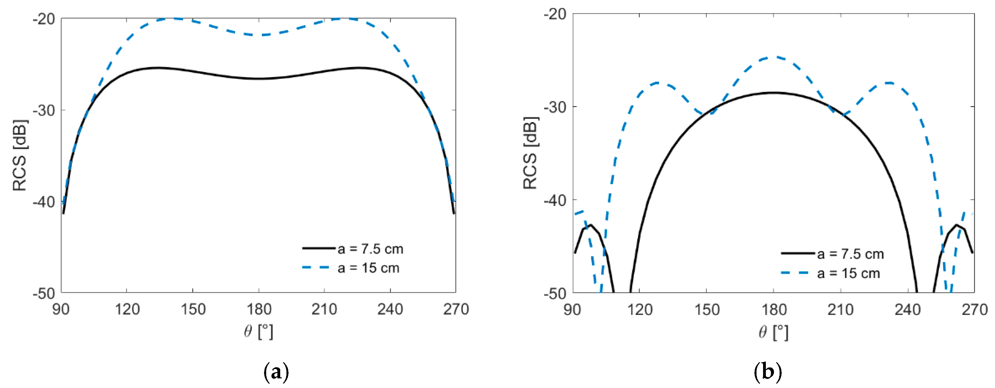
The far-field radar cross section (RCS) [
17] as a function of the scattering
θ is reported in
Figure 6, evaluated in the presence of a wall (
L = 20 cm, ε
r1 = 4), for a dielectric cylinder with permittivity of a biological medium (ε
rc = 50, σ = 1 S/m) in
Figure 6, and for a low permittivity target modeling a wood rod (ε
rc = 2.5, σ = 0.004 S/m), at the frequency of 1 GHz, in
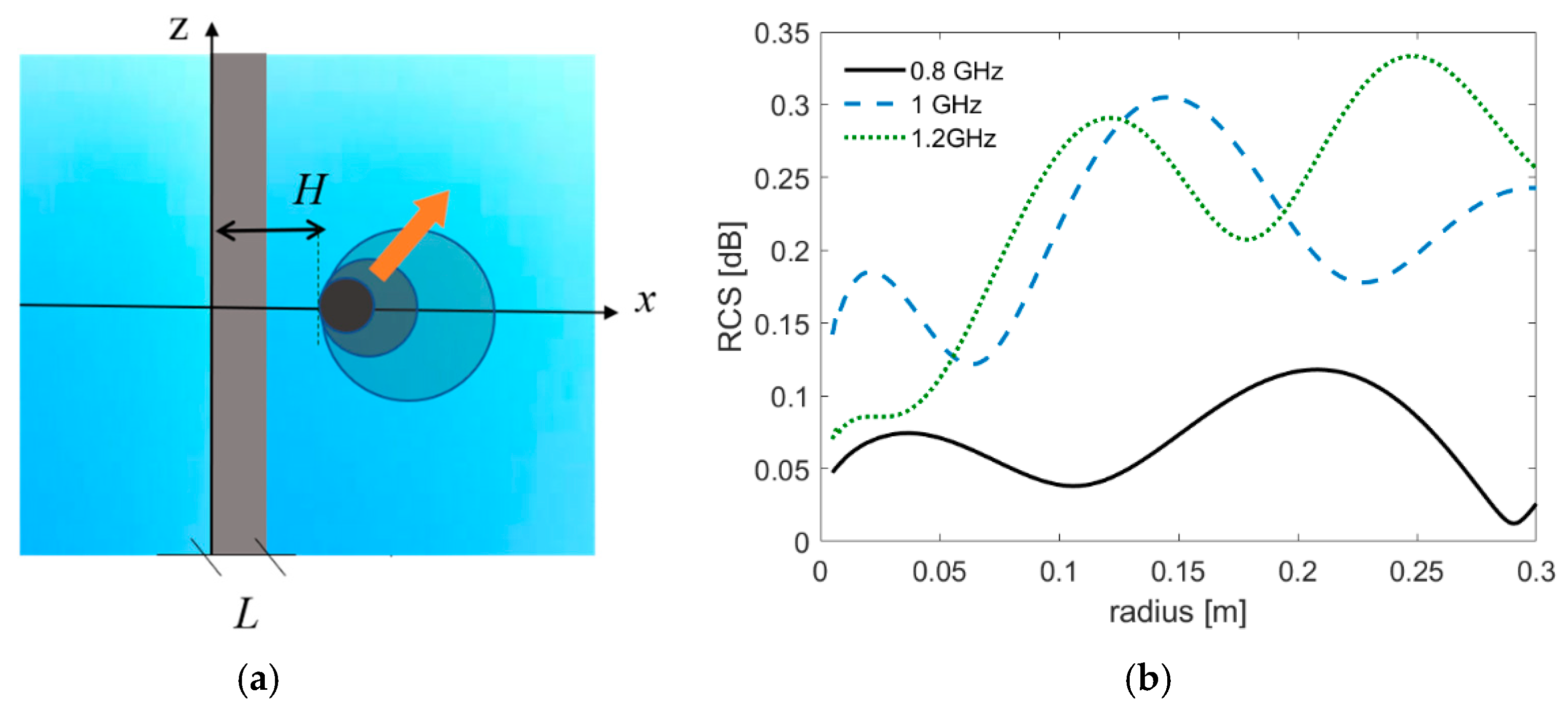
Figure 6b. The targets have a fixed center in (0, 0.5 cm), and two different radii of 7.5 cm and 15 cm are simulated. The source is given by a plane wave field. Comparison between the two dielectric targets showed a consistent reduction in the radar cross-section in the low-permittivity case which was more pronounced for the largest radius. The behavior of the radar cross section can also be estimated in the backscattering direction
θ = 180° for different values of the radius
a, as in
Figure 7. A PEC target was used in the plot. As with dielectric targets, the internal reflections led to a less regular pattern. The results, calculated at three frequencies (800 MHz, 1 GHz, and 1.2 GHz), showed that different positions of the resonances were shifted coherently as the size of the wavelength was varied at a fixed cylinder’s radius.

