1. Introduction
The microstrip antenna has many excellent features satisfying the requirements of the current wireless communication system being low-profile, easily manufactured, easy to integrate, with multi-polarization, multi-band operations, etc. However, it has some critical limitations too, such as narrow bandwidth, poor gain and higher cross-polarization [
1]. In particular, cross-polarization leading to cross-talk is a severe issue in a communication system.
There is extensive literature on the bandwidth and the gain enhancement techniques. Hence, current generation microstrip antennas are capable of handling ultra-wide bandwidth [
2] and exhibiting a peak realized gain above 20 dBi [
3]. Among the different techniques of gain enhancement, the metamaterial-based technique is commonly used in the literature to intensify the gain of the antenna. A variety of metamaterial structures are reported in the literature to either intensify or shield the electromagnetic radiation. Double negative metamaterials are useful for backward wave propagation. A single negative metamaterial acts as a perfect reflector and is thus, effective for electromagnetic shielding. However, in many cases the single negative metamaterials are deployed beneath the antenna to reflect radiation back towards the broadside direction to enhance the antenna gain. In [
4,
5,
6], phase-gradient based multilayered structures are utilized to intensify the radiation of the antenna in a particular direction, leading to excellent directive gain. In [
7], Fabry Perot based metamaterials are placed over a conventional rectangular patch antenna and contraction of the main lobe is demonstrated, resulting in an improved gain. Xu et al. have detailed a zero refractive index based metamaterial and demonstrated its lensing ability by contracting the HPBW by 4.9°, and 6.7° in the E and H-planes respectively [
8]. They have implemented fractal, spiral, and meandered-based strategies to achieve the 3D anisotropic zero-refractive-index metamaterials. In [
9,
10], backward-wave propagation is demonstrated using left-handed materials. The metamaterial-based technique is based on, either the zero-refractive index, phase compensation using the gradient refractive index, or the Fabry-perot resonant cavity, where metamaterials are placed at a certain distance from the antenna to direct the radiation in a particular direction. Different metamaterials [
4,
5,
6,
7,
8,
9,
10] reported in the literature have unique qualities in terms of their structure, design simplicity, and effectiveness. However, there is still scope to develop a simplified metamaterial structure to allow easy fabrication, and integration.
Another critical issue of microstrip antennas is their high cross-polarization level for which very few dedicated techniques are reported in the literature. A higher cross-polarization level results in strong cross-talk [
11] and is thus extremely threatening to applications like wireless medical telemetry services (WMTS), medical implant services (MICS), military and avionic communications.
Defected ground structure (DGS) is widely used to suppress the cross-polarization [
12,
13,
14,
15]. Recently, in [
12], Kumar et al. presented a rectangular DGS to suppress the cross-polarization of a graphene-based antenna in the elevation plane. In [
13], a dumbbell-shaped DGS is reported to achieve a co-cross-polarization isolation of more than 30 dB for a rectangular patch antenna. Similarly, in [
14,
15], different DGS structures are employed to suppress the cross-polarization of rectangular patch antennas. However, a few other techniques such as aperture coupling [
16], metamaterial based [
17,
18], and differential feeding [
19], are also reported in the literature to suppress the cross-polarization of non-conventional antennas.
In this work, efforts are made to improve the antenna co and cross-polarization isolation as well as gain of a microstrip antenna. Two independent techniques-a shorted defected patch structure (DPS) and installation of the High Reflective Frequency Selective Surface (HRFSS) superstrate are reported to improve the cross-polarization and the gain of the antenna respectively. However, the idea of slot-loaded patch is well-known to obtain the multiband [
20], reconfigurable [
21], and wideband [
22] it is rarely used to suppress the cross-polarization level. In addition, the size of the aperture type unit cell used to develop the proposed superstrate is nearly 27% compact than the reference [
23] unit cell which significantly reduces the overall structure. The proposed work uses the DPS for the narrowband application but it is also effective for the wideband cross-polarization reduction without affecting the gain of the antenna, as reported in [
24]. The width of a rectangular patch antenna is shorted to the ground using a shorting-pin and an optimized thin slot is incorporated near to the shorting-pin, resulting in co-cross-polarization isolation of more than 30 dB in the elevation plane. Moreover, the proposed technique does not disturb the principal pattern of the rectangular patch antenna. Due to the non-conventional patch structure, the feeding location is optimized to perfectly match the 50
SMA connector. Thereafter, an aperture type miniaturized superstrate is installed over the antenna to enhance the gain which is inspired by [
23,
25,
26]. As the air-gap affects reflection coefficient [
25] of both antenna and the superstrate, optimization of air-gap is required to synchronize the resonant frequency. The height of the superstrate is optimized at 34 mm achieving best possible synchronization resulting in an excellent peak measured realized gain of 10.65 dBi. The characterization of the superstrate is done by analyzing the HRFSS unit cell in the context of transmission characteristics. Finally, a prototype of the proposed technique is developed which is intended to work in the S-band and good agreement between the simulation and measured results have been found.
2. Defected Patch Antenna
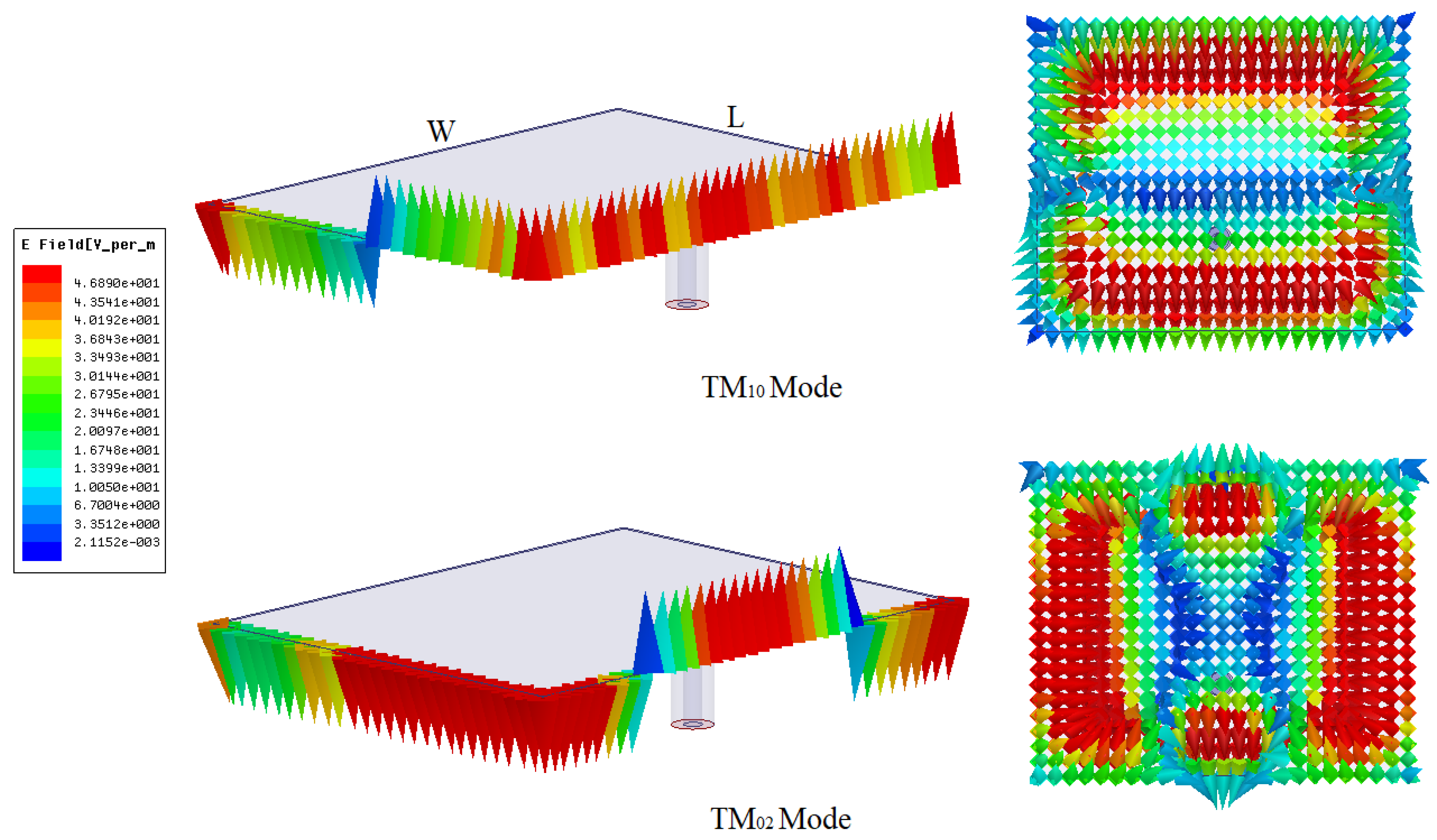
Ideally, in a conventional rectangular patch antenna, the current covers a half-wavelength path along the length (L) (
Figure 1) and radiates only at the edges of the width (W). In a practical situation, some radiation occurs along the length of the patch, caused by the immediate higher-order orthogonal TM
mode.
The electric field variation along the length and width, and into the substrate is shown in
Figure 1. However, in the TM
mode, the current travels along the width and radiates along the length, as shown in
Figure 1. It is evident in
Figure 1 that in orthogonal TM
mode, the strongest electric field is present at corners and at a position of
. If the position
is shorted to the ground, the radiation caused by the TM
mode can be significantly suppressed, resulting in lower cross-polarization for the dominant TM
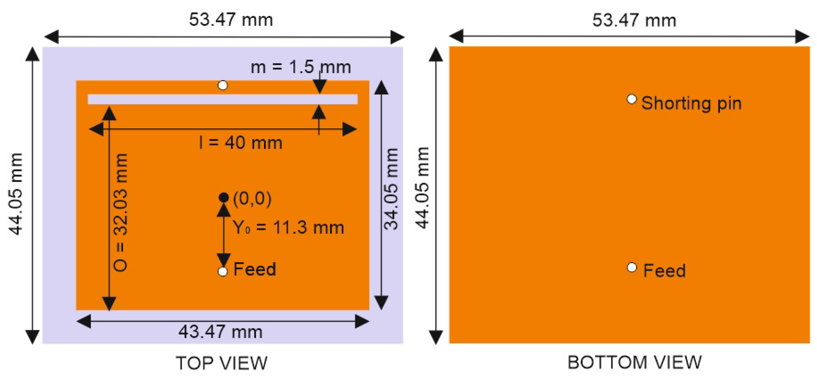
mode. Shorting the patch and ground will alter the edge-impedance of the patch, thus, the feeding location should be relocated. In this section, the concept is deployed on a rectangular patch antenna designed using a low-cost FR4 substrate of thickness 1.6 mm, and dielectric loss tangent (
) of 0.02 at the 2.2 GHz band. Thereafter, a thin rectangular slot is placed near to the shorting-pin to divert the current along the width, which further enhance the co-cross-polarization isolation. The layout of the antenna is shown in
Figure 2. In the first iteration, a conventional rectangular patch antenna is designed using a resonant cavity model [
1]. Later, the patch and ground are shorted and the feeding location is optimized to obtain the best possible impedance matching.
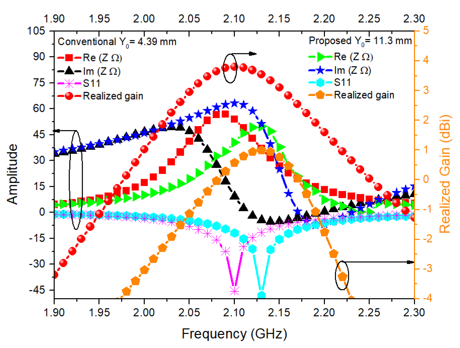
The proposed design is evolved in two stages, shorting the patch and ground and incorporating the DPS. The impedance, reflection, gain characteristics of a conventional and the proposed antenna with optimized feeding location is shown in
Figure 3. It is evident in
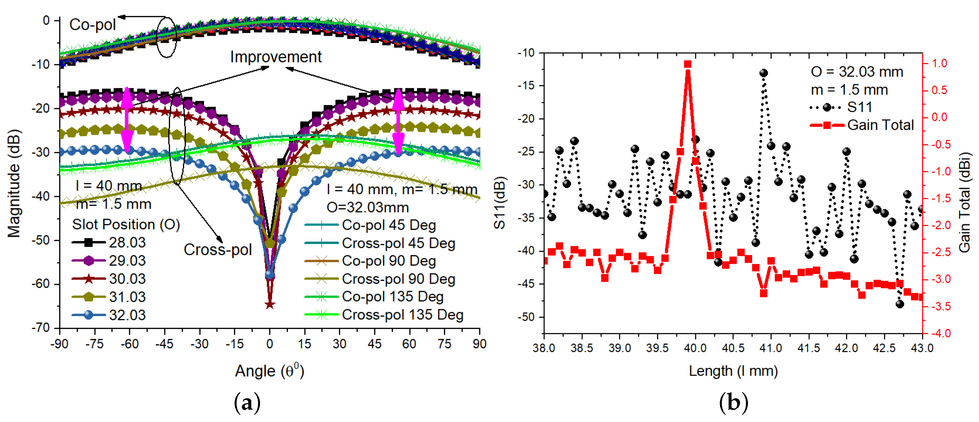
Figure 3 that, the conventional antenna and the proposed design achieves the best possible impedance matching at 2.1 and 2.2 GHz with different feeding location respectively. However, after implementing the shorting pin and DPS the gain of the antenna is significantly reduced. Initially, a random slot is incorporated into the patch near the shorting pin and the cross-polarization of the rectangular patch antenna is analyzed against the position of the slot (O). The co and cross-polarization levels for the different elevation angles of the proposed antenna against the position of the slot (O) is shown in
Figure 4a. It is found that, as the slot shifts closer to the shorting pin, the cross-polarization level improves significantly. However, beyond O = 32.03 mm, the cross-polarization level starts to degrade, thus, the position of the slot is set to this location. The co and cross-polarization levels have been studied for the elevation angles
,
, and
and found satisfactory, as shown in
Figure 4a. The length of the slot versus the S11 parameter and antenna gain is shown in
Figure 4b.
It is clear that the entire range of the slot length (l) satisfies the S11 parameter below −10 dB, although the gain of the antenna is extremely sensitive to the length of the slot. Thus, very precise optimization is required to achieve the best possible antenna gain. Similarly, using high-frequency-structural-simulator (HFSS) optimetrics, considering the cross-polarization, antenna gain and reflection coefficient the width (m) of the slot is optimized to 1.5 mm. The co-and cross-polarization of the conventional and of the shorted and the final design in different elevation angles and the parametric analysis of slot width (m) and via radius are shown in
Figure 5. The co-and cross-polarization of the conventional and of the shorted and the final design in different elevation angles are shown in
Figure 5a. It is evident in
Figure 5 that the shorted ground with the DPS has excellent isolation nearly below 30 dB in the broaside (
). However, for the other elevation angles (
,
, and
) the shorted and shorted with DPS structure have a cross-polarization level difference of around 5 dB. A precise optimization is done against the slot width and via radius which is depicted in
Figure 5b,c. It is found that the slot width and via radius is also affecting the CP-XP isolation. An optimum result is obtained for the slot width of 1.5 mm and via radius of 0.695 mm. While analysing the slot width effect, the distance between the shorting pin and DPS is also considered.
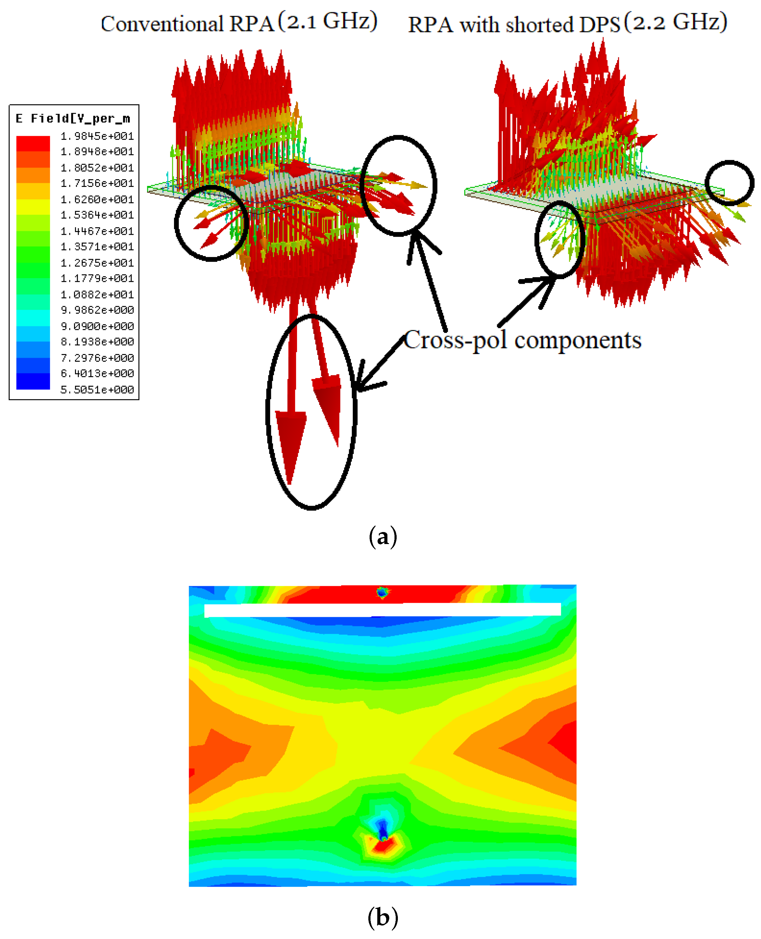
The electric field vectors into the substrate and the surface current distribution of the proposed design are shown in
Figure 6. The suppression of the cross-polarization level can be explained by the electric field vectors into the substrate and the surface current distribution, as shown in
Figure 6a. In a conventional probe-fed rectangular patch antenna, the cross-polarization components occur at the feeding location as well as at the corners of the patch. It is apparent in
Figure 6a that, after implementing the proposed techniques on a conventional rectangular patch antenna, the cross-polarization components at the feeding location and at the corners of the patch are suppressed, resulting in an extremely poor cross-polarization level. Similarly, the surface current distribution shown in
Figure 6b clearly depicts that the shorting pin attracts maximum current toward it reducing the current flow at corners resulting in improved cross-polarization.
To analyse the effect of the shorting pin, and DPS structure, some basic parameters of the conventional antenna is compared with the proposed antenna, as presented in
Table 1. It can be seen that, the antenna center frequency, and the bandwidth is slightly affected whereas the antenna gain is severely reduced. However, the proposed design achieves an excellent CP-XP isolation of 30 dB. In the following section, a superstrate integrated technique is implemented to further improve the antenna gain.
3. Superstrate Integrated Antenna
The rectangular patch antenna with DPS has excellent co-and cross-polarization isolation. However, the shorting pin attracts the maximum current towards it which reduces current flow near edges of the width. Thus, a small amount of desired radiations along width is also being eliminated causing a degraded gain of around 1 dBi. Hence, to enhance the gain of the antenna, an HRFSS-based superstrate built on 1.6 mm thick FR4 substrate is installed above the antenna, leading to contraction of the main lobe and improved gain. In this section, the superstrate is characterized using transmission parameters and the performance of the superstrate-integrated antenna is discussed. The layout of the unit cell and superstrate is shown in
Figure 7.
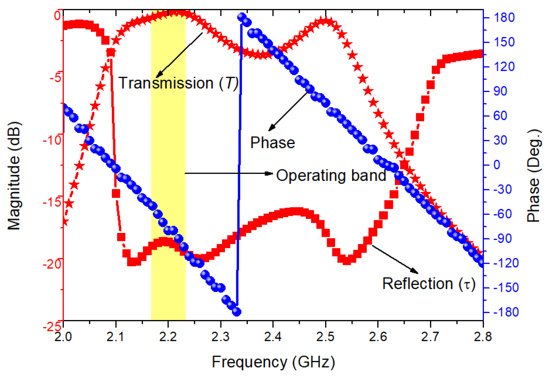
To analyze the unit cell, periodic boundaries are applied in the HFSS and the scattering parameters are extracted. Later, using the following expressions the transmission (T) and reflection (
) coefficients and material parameters are calculated [
27]:
It is evident in
Figure 8 that the proposed unit cell supports wideband from 2.1 GHz to 2.54 GHz with excellent transmission coefficient and reflection coefficient below −18 dB which thus ensures the Anomalous Refraction (AR) [
4]. The reflection phase of the unit cell is also presented in
Figure 8 which clearly depicts the three zero-crossing points and also confirms the Anomalous Refraction. The superiority of the proposed superstrate is presented in
Table 2. It is clear that the proposed aperture type superstrate is compact and exhibits improved gain compared to the [
23].
The proposed antenna is matched to a narrowband from 2.16 GHz to 2.23 GHz which lies within the range of the unit-cell. It is clearly discussed in [
23] that a larger superstrate array placed at an optimized height exhibits higher gain/directivity. In this work, to limit the overall size of the structure a small 5 × 5 unit cell array (58.6 × 58.6 mm
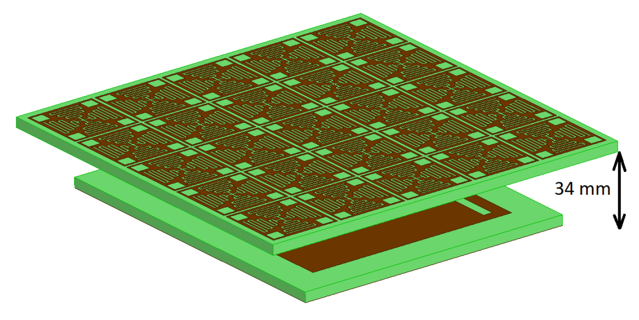
) is utilized exhibiting sufficiently measured higher gain of 10.65 dBi. In addition, the position of the superstrate significantly affect the resonant frequency and reflection coefficient thus, a precise optimization is required. The optimum distance between the antenna and the structure is estimated to 34 mm (0.233
) through optimization, as shown in
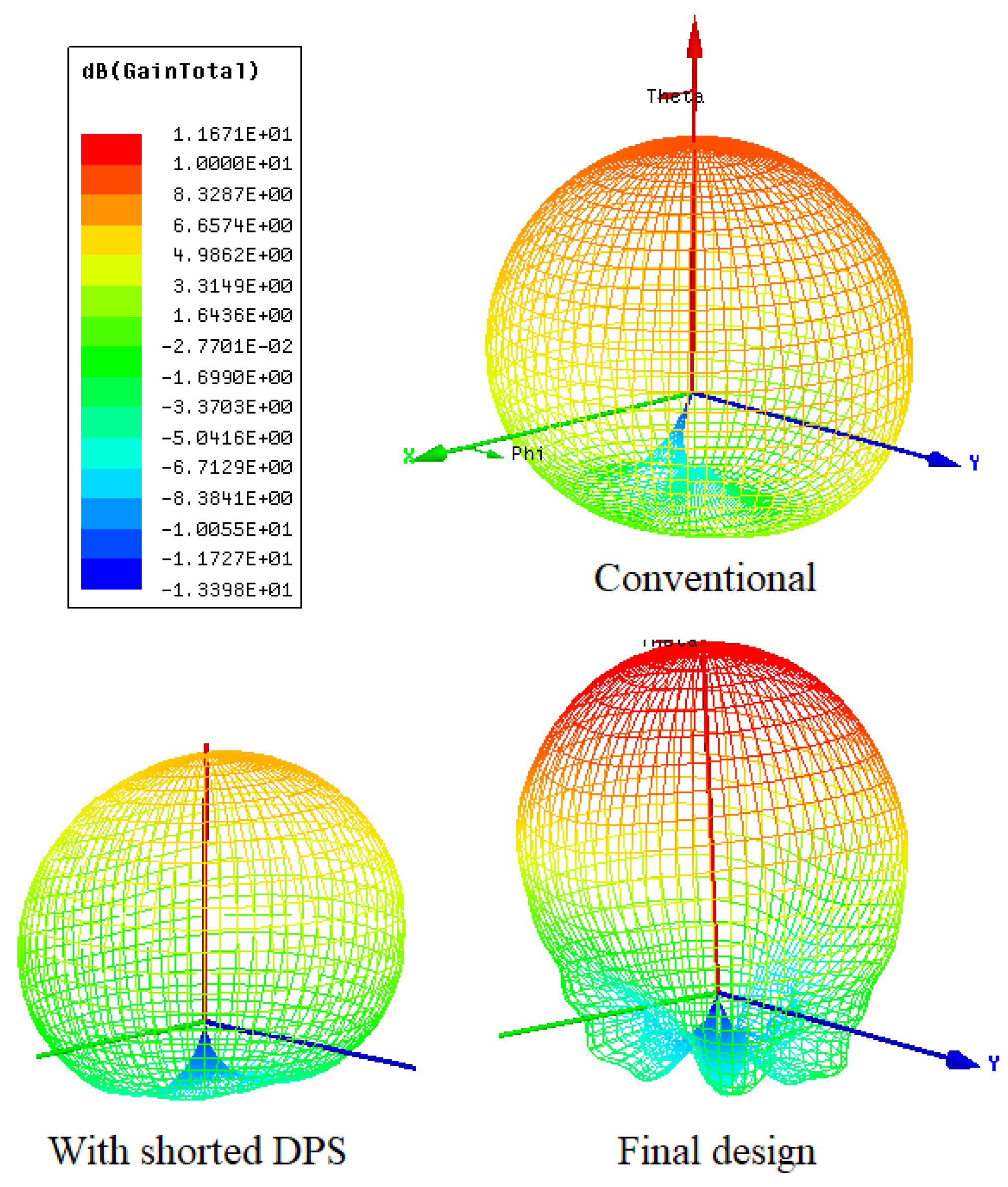
Figure 9. The 3D polar gain total of the conventional rectangular patch antenna, the rectangular patch antenna with the shorted DPS, and the superstrate integrated final design are shown in
Figure 10. The contraction of the HPBW and the enhancement of the antenna gain of the superstrate-integrated final design can be clearly observed in
Figure 10. The conventional rectangular patch antenna and the shorted rectangular patch antenna with the DPS have nearly equal gain and HPBW. However, the rectangular patch antenna with the shorted DPS has excellent co and cross-polarization, as discussed in the earlier section. The HPBW of the final design is reduced by nearly 67%, so, a simulated total gain of 11.67 dBi is achieved, as shown in
Figure 10. To validate the above concept, the prototype of the antenna structure is fabricated and the measured results are compared with the simulated results in the following section.
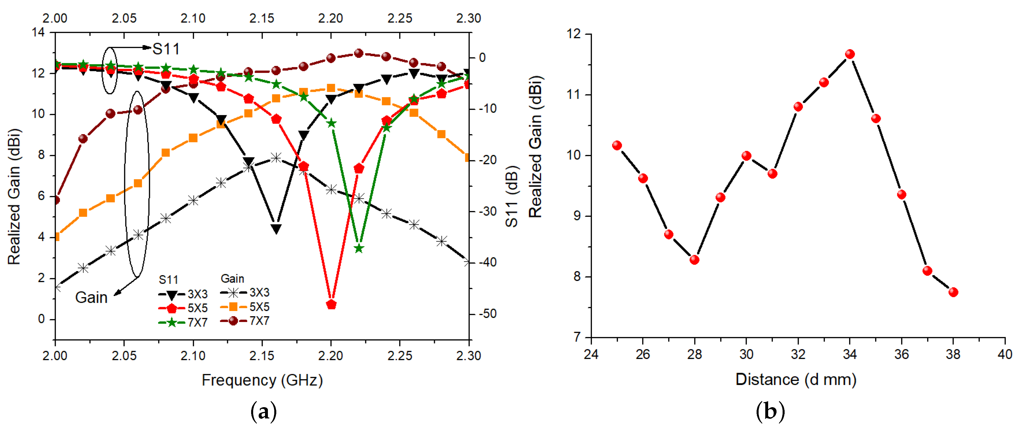
The size and the position of the antenna is analysed and shown in
Figure 11. It is evident in the
Figure 11a that as the size of the superstrate is increasing the gain of the antenna is increasing. Also, for the different superstrate size the center frequency of the overall design is also shifting. Thus, it is essential to precisely optimize the superstrate size before the implementation of the proposed concepts. The simulated realized gain of the propose design against the position of the superstrate of size 5 × 5 is shown in
Figure 11b. From
Figure 11b it is learned that the proposed structure exhibits maximum realized gain when the superstrate is installed at a height of 0.43
.
Prototype and Measured Results
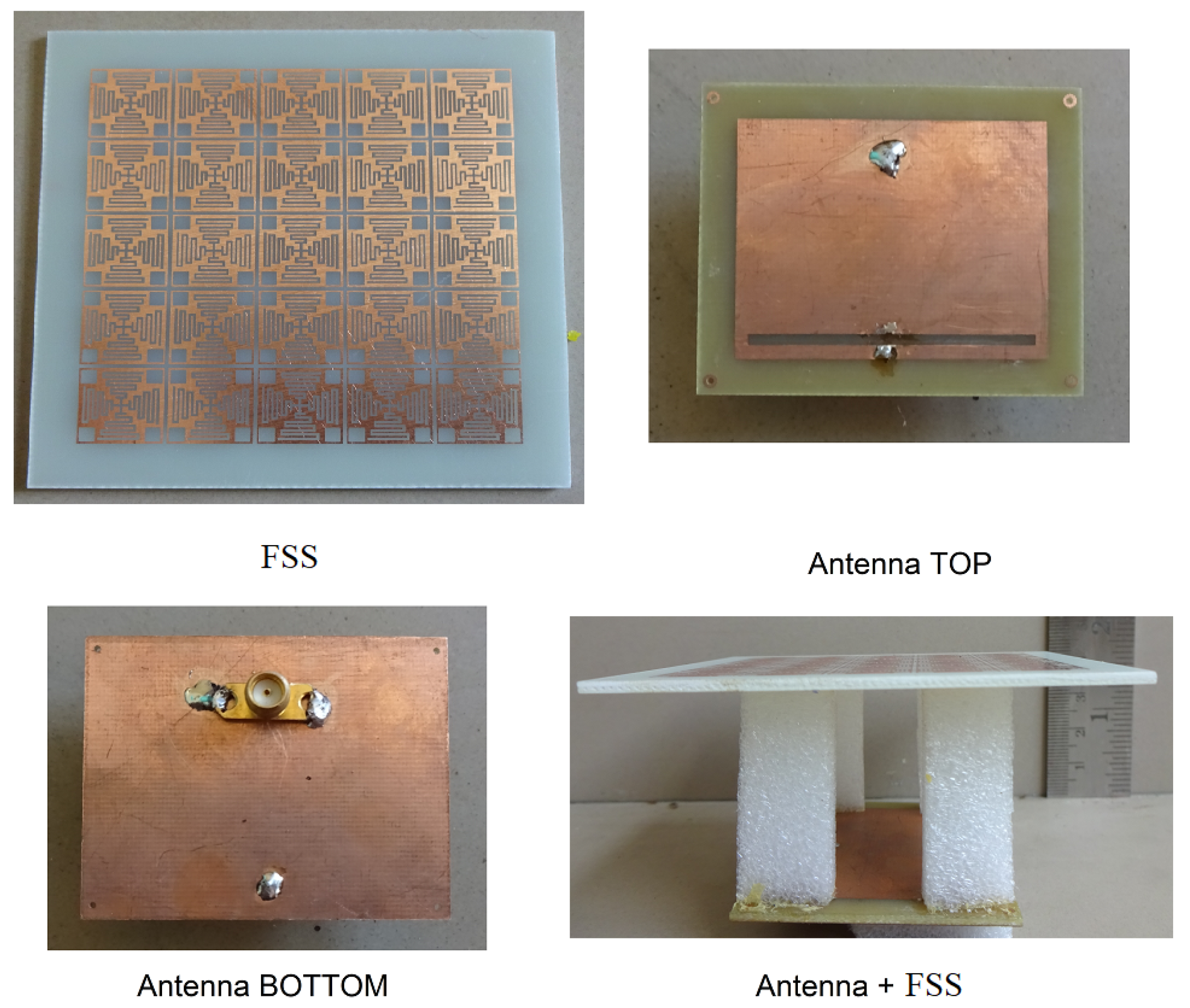
The prototypes of the superstrate, antenna and superstrate-integrated antenna are shown in
Figure 12. The prototype of the proposed design is precisely fabricated, leading to an excellent agreement between the simulation and measured results. The measured results have slight deviations/error ensuring the realization of the proposed design. To install the superstrate over the antenna, four foam pillars of height 34 mm are pasted at the corners of the antenna, as shown in
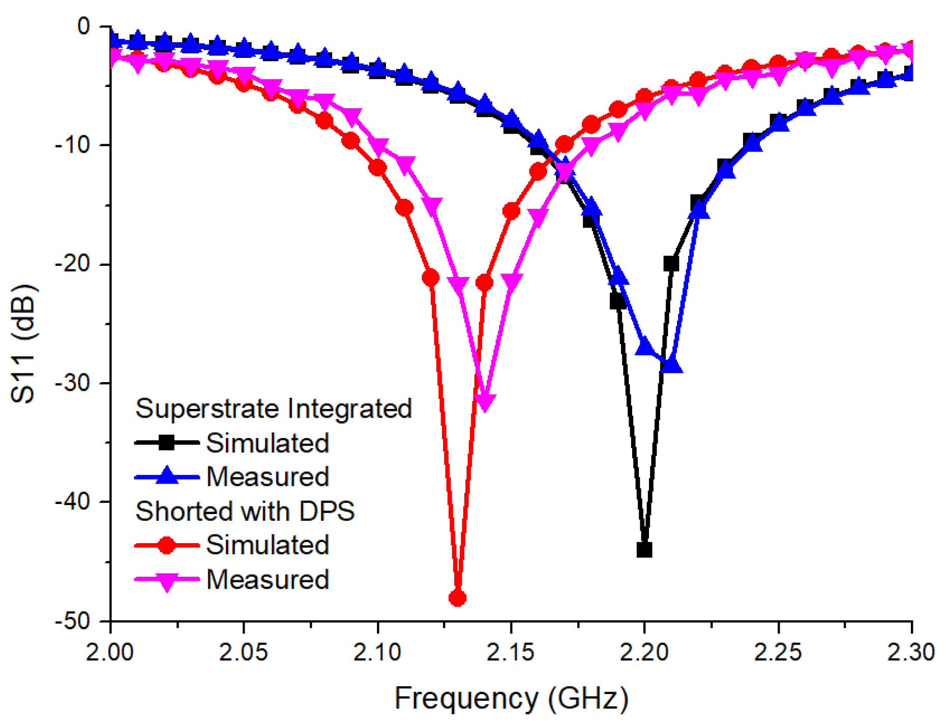
Figure 12. The S11 parameter and the realized gain of the antenna are measured using a Vector Network Analyzer and the two-antenna method respectively. The radiation pattern of the antenna is measured in an electromagnetically shielded chamber. The simulated and measured S11 parameter of the proposed antenna with and without superstrate are shown in
Figure 13. It is clear in
Figure 13 that the loading of superstrate is significantly shifting the frequency. A slight shift in the measured S11 parameter of the superstrate integrated configuration can be seen in
Figure 13. The main reason for the deviation in the simulated and measured S11 is the mismatch between the dielectric constant in simulation model (ideal considerations,
= 4.4) of the substrate and a practically used substrate. In addition, in the simulation, an ideal 50
port is used to excite the antenna.
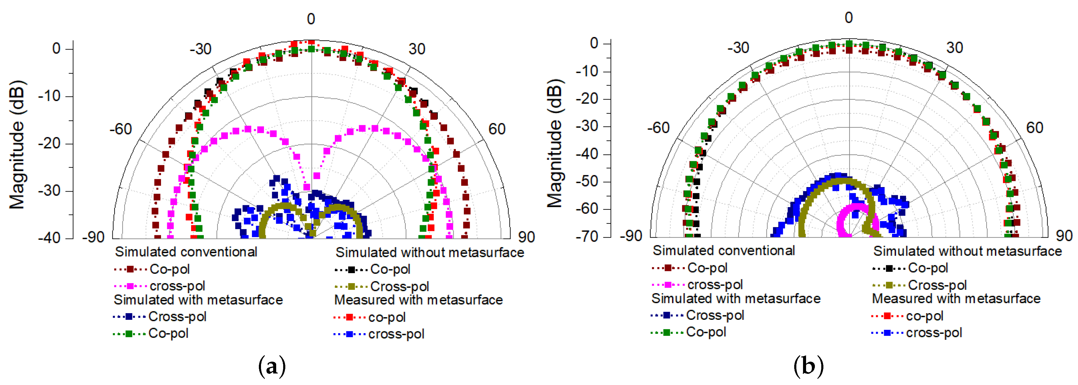
In practice, a subminiature version-A (SMA) connector is used to feed the antenna, which includes some losses, leading to a slight mismatch between the simulated and measured results. However, this mismatch can be overcome using high accuracy substrate and feeding connectors. The proposed antenna has a measured 64 MHz, −10 dB impedance bandwidth covering from 2.169 GHz to 2.233 GHz. The broadside co-and cross-polarization radiation patterns of the conventional antenna, the proposed antenna without superstrate, and with superstrate at 2.2 GHz are depicted in
Figure 14. It is evident from
Figure 14 that there is a considerable agreement between the simulated and measured co-and cross-polarization levels of the superstrate-integrated antenna.
It can be seen in
Figure 14a that, after the integration of the slot into the patch and superstrate the cross-polarization level in the H-plane is degraded. However, due to the propagation of the dominant transverse magnetic (TM)-mode, the cross-polarization of the patch antennas is extremely low (<−40 dB). Hence, this degradation has a negligible effect on the antenna performance.
The measured cross-polarization level in the elevation plane is below −30 dB, as shown in
Figure 14b. However, due to the dominant transverse magnetic mode, the microstrip antennas always have a good co-and cross-polarization isolation level in the azimuth plane. Moreover, for both elevation and azimuth planes, there are considerable fluctuations in the measured cross-polarization levels. This is due to the lower power level of the cross-polarization radiation and the sensitivity of the power meter. The back radiations from the surroundings may also produce an erroneous measured pattern which is more severe at low power level measurement, as cross-polarization. There is a good agreement between simulated and measured co and crosspolarization levels in the E-plane (
) and H-plane (
). Thus, similar agreement is also expected at
, and
. The E-plane half-power-beamwidth is reduced from 88
to nearly 40
after integration of the superstrates which ensures the significant gain enhancement, as depicted in
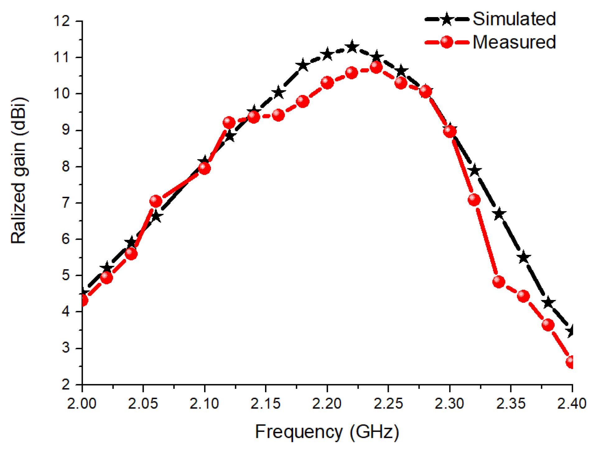
Figure 14a. Whereas, in the H-plane there is a minor improvement. The simulated and measured realized gain of the antenna is shown in
Figure 15. It is evident in
Figure 15 that the integration of the superstrate is enhancing the gain of the antenna by nearly 9.65 dBi achieving the peak realized gain of 10.65 dBi.
The proposed structure has excellent co and cross-polarization isolation, improved gain, and narrow HPBW. Thus, it can be used for directive secured communication applications. The proposed work is compared with existing work as reported in
Table 3. It is evident in
Table 3 that the existing work focuses either on gain enhancement or cross polarization reduction. The high gain antennas [
4,
6,
8] have moderate cross-polarization level of around −15 dB. Similarly, the low cross polarization antennas [
12,
13,
14,
15] have moderate gain. However, the antenna proposed in [
15] exhibits comparable performance due to the higher operating frequency. In this work, both, gain enhancement and cross-polarization improvement techniques are applied and the remarkable results are obtained.


