1. Introduction
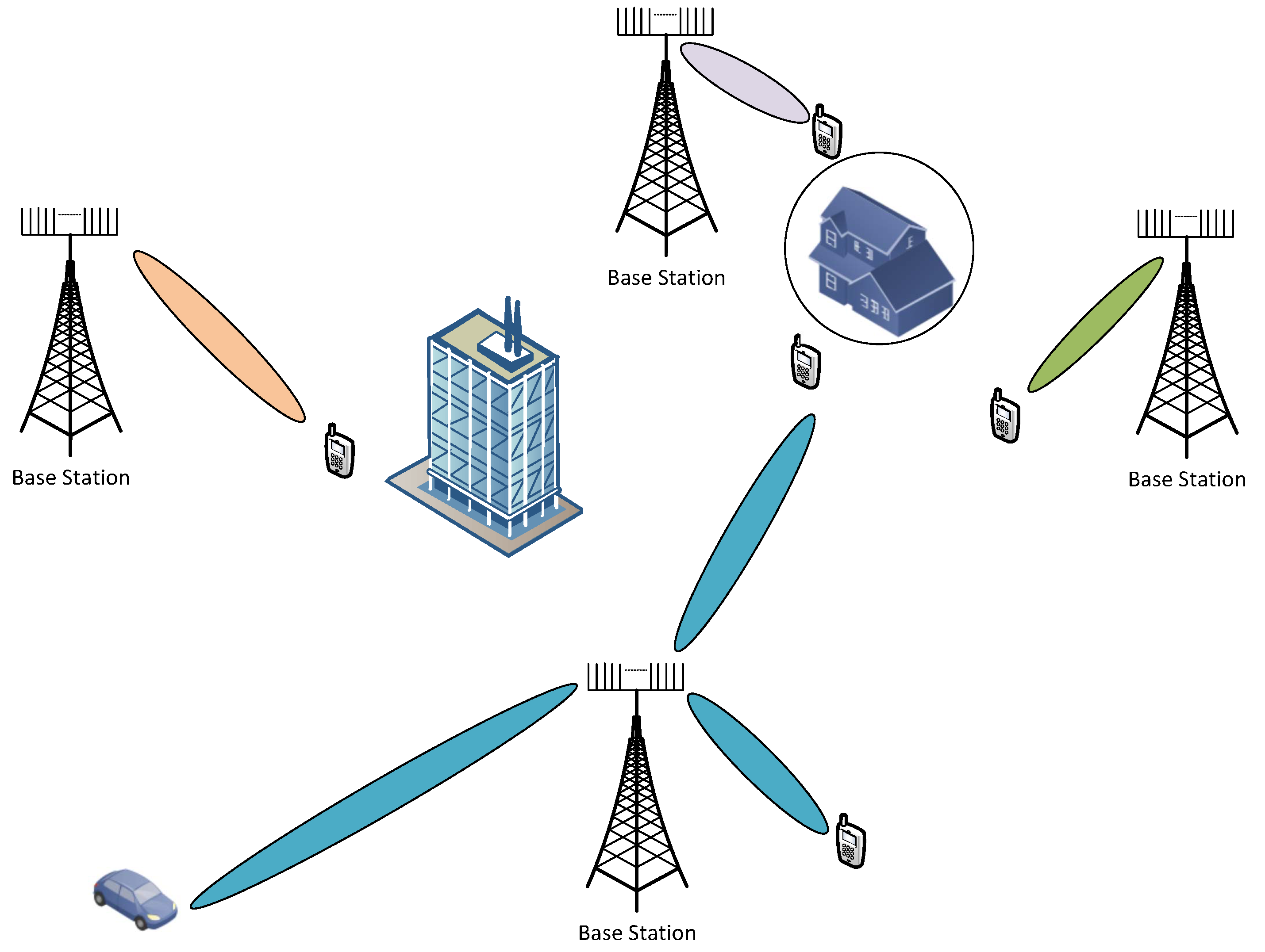
The scarcity of available frequency band for wireless communications has led to the inclusion of millimeter Wave (mmWave) frequencies in cellular communications. This has opened the doors for massive multiple-input multiple-output (MIMO) systems. Due to high transmission frequencies, fabrication of large number of antennas with small form factor has become possible. MmWave band has inherent hindrances, like, high path-loss and absorption-loss. It has been known that MIMO systems advantages (spatial multiplexing or diversity gain) are scaled-up with the number of antennas. In summary, one can enjoy the benefits of the large bandwidth available at mmWave frequencies by combating high path and absorption losses with massive MIMO directional beamforming. Future mmWave massive MIMO-based cellular networks will be as shown in
Figure 1. Due to the high pathloss on one hand and high directional gain on the other hand, the inter-cell interference and cell boundaries will become meaningless. The fixed area size cell boundaries of traditional cellular will probably no longer exist in the future mmWave massive MIMO systems. Narrow beams can serve distant user equipment (UE) without interfering other UEs provided that there is no obstacle between BS and intended UE, whereas a closely located UE may deprive of connection due to the obstacles.
The cost of massive MIMO is in terms of excessive feedback overhead for channel estimation along with the hardware complexity of RF chains (increased number of radio-frequency (RF) chains). The feedback overhead has been tackled separately for frequency division duplex (FDD) and time division duplex (TDD) systems. In FDD systems, the uplink channel estimation consists of fewer overheads compared to the downlink channel estimation, because generally, the number of transmit antennas
is larger than the number of users
K, and the number of receive antennas per user
(
and
). The most common technique to reduce the downlink channel estimation overhead is joint spatial division multiplexing (JSDM) [
1]. The JSDM uses two-stage precoding: second order channel statistics (covariance)-based user grouping and the traditional MU-MIMO linear precoding (zero-forcing) for the inter-user interference mitigation based on the low-dimensional effective channel. In TDD, only uplink channel estimation is done and the downlink channel estimates are obtained by the transpose of the uplink channel using the channel reciprocity principle. The TDD massive MIMO systems suffer from pilot contamination when the BS receives non-orthogonal pilot signals from the neighboring cells. This pilot contamination degrades the channel estimation and hence, affects both uplink combining and downlink precoding.
In traditional MIMO systems, a separate RF chain (analog-to-digital converter/digital-to-analog converter, serial-to-parallel/parralel-to-serial converter, up/down converter etc) is required for each antenna, but the high power consumption makes it infeasible for the case of massive MIMO systems. Hybrid beamforming technique resolves this problem by dividing the precoding/combining into baseband digital processing and RF analog processing. The hybrid precoding and combining offer extra degrees of freedom in space domain with a large number of antennas and analog beamforming [
2]. The hybrid beamforming can be realized by using MU-MIMO precoding as baseband digital precoding and the statistical channel state information-based pre-beamforming as RF analog precoding. This limited feedback (due to average CSI) configuration is particularly suited for massive MIMO mmWave systems with a large number of antennas but relatively small number of RF chains [
3]. It has been shown [
4], that the covariance-based limited feedback works well for mmWave massive MIMO systems, where the number of users is small with respect to the number of BS antennas and the channels are formed by a few multi path components (MPCs) with small angular spread.
Limited work has been done on the joint multiuser massive MIMO resource allocation and hybrid beamforming design. Although mmWave massive MIMO system has a potential of tremendous increase of spectral efficiency. However, the cost and power consumption of power-hungry radio frequency chains (analog-to-digital converter (ADC)/digital-to-analog converter (DAC), parallel to serial converter, serial to parallel converter, up converter/down converter) make it impractical to build a complete RF chain for each antenna. A promising solution to this problem is hybrid beamforming, where the precoder at the transmitter is divided into two parts: analog precoder and digital precoder. The analog precoder (usually a network of phase shifters) at the RF stage reduces the number of RF chains required for the digital precoder. In order to configure these precoders, the transmitter requires channel state information in the form of uplink feedback from users, but in the presence of massive antennas, this feedback becomes a huge load on the wireless uplink, especially in FDD mode. JSDM [
4] is a technique used to reduce the feedback overhead. It uses slowly varying average channel statistics to implement the analog precoder; then, the digital precoder is realized by using a low-dimensional effective channel. Till now, different variants of the JSDM have been proposed. Li et al. [
5] generalize the JSDM scheme to support non-orthogonal virtual sectorization and with multiple RF chains at both link ends. It uses the Kronecker channel model to decouple the transmit and receive beamforming. Under this channel, the analog beamformer is obtained by stacking strongest eigenbeams of the channel covariance matrix and then the digital beamformer is based on a weighted minimum mean squared error (MMSE) with effective channel. However, the Kronecker model does not characterize the mmWave channel where transmitter and receiver have coupling effects due to highly directional transmission. In [
6], the authors apply JSDM using a geometrical channel model and find hybrid precoder and combiner at transmitter and receivers, respectively. Hybrid beamforming with switches (HBwS) has been introduced in [
7], where,
analog beamformer is controlled by
instantaneous CSI based switches.
is the number of transmit antennas,
is the number of RF chains, and
. Another switch-based analog beamforming is proposed in [
8] but it requires instantaneous CSI for both switching network and the phase shifter network. Also it contains
. The JSDM implementation also requires the training in the downlink to estimate the channel covariance matrix. Most of the work assumes that the CSI is known at both ends. In [
9], authors consider the joint optimization of the training resource allocation and channel-statistics-based analog beamformer design by using user centric virtual sectorization. There are different structures for the phase shifter-based analog beamformer, namely, fully connected, sub-connected, and dynamically connected [
10]. Park [
11] investigate JSDM with these analog beamformer architectures. The dynamic architecture gives better result at the cost of added complexity. In [
12], authors propose a hybrid beamforming method with unified analog beamformer by Subspace Construction (SC) based on partial CSI in massive MIMO OFDM system. In [
13], statistical CSI based analog beamformer uses regularized block diagonalization to mitigate the inter-group interference and instantaneous CSI based digital beamformer utilizes the weighted MMSE to suppress intra-group interference. Jiang et al. [
14] jointly optimize the user selection and beam selection during analog beamforming design. They use Lyapunov-drift optimization framework to obtain the optimal solution. Their work only focuses on the design of statistical CSI based analog precoder and user/beam selection. Our previous work [
15] on resource allocation for transmit beamforming develops digital and analog precoders which maximize the sum rate with total power and desired number of RF chains constraints. The provided solutions require full instantaneous CSI at the transmitter and receiver, which, in case of the massive MIMO, consists of large number of pilot transmission in downlink and channel information feedback in the uplink. In this work we exploit the channel similarities by grouping (K-Mean machine learning) the users based on the location information. Low complexity DFT matrix based analog precoder is derived using statistical CSI. This greatly reduces the feedback overhead for the design of zero-forcing digital precoder.
Machine learning (ML) applications for the physical layer of wireless communication systems have been widely reported in [
16]. Most of the conventional transmitter and receiver blocks can be replaced by an ML-based auto encoder as suggested by the authors. The large number of antennas in massive MIMO leads to the challenging issue of channel estimation in mmWave communications. A common practice in TDD massive MIMO systems is to utilize the channel reciprocity to get the downlink CSI from uplink channel information estimates. However, in FDD, the channel reciprocity is not applicable and the downlink CSI estimation is very difficult. The downlink channel estimation is known to be hampered by the pilot contamination effect (user to base-station). The quality of channel estimates is deteriorated by the mutual interference caused by the non-orthogonal pilots in a cell. In [
17], a supervised learning-based pilot decontamination scheme for massive MIMO uplink is reported. In the proposed ML-based solution, the users’ locations in all cells and the pilot assignments stand for the input features and output labels, respectively. In [
18], a deep learning network CsiNet is used to learn the CSI-to-codeword transformation (codebook approach is usually adopted to reduce the feedback overhead) at users’ terminals and inverse CsiNet at base-station. The authors of [
19], suggest a learning-based antenna selection for massive MIMO systems. It uses a multiclass K-NN and support vector machine (SVM) for data-driven optimal antenna selection. Wang et al. [
20] employs K-nearest neighbor
supervised learning for the
N beams allocation among
K users. In [
21], a reinforcement learning based framework for radio resource management in radio access networks has been proposed. In our previous work [
22], we used neural networks to reduce the execution time of the computationally intensive resource allocation part of the joint resource allocation and hybrid beamforming design in [
15]. However, in this work, we use K-mean based unsupervised machine learning scheme to group the users based on their spatial locations. To the best of our knowledge, there is no research work that jointly consider the spatio–radio resource management and the hybrid beamforming in massive MIMO systems.
In this work, we use spatial channel covariance matrices for the analog beamforming design. We also consider the users to RF beam mapping. This mapping requires channel state information and a search over all possible beam combinations at the base-station. This search is exponential in the number of users [
23]. Due to this exponential increase in complexity, we use DFT-based eigenmode beams with RF switches.
Contribution: In this paper, we develop joint spatio–radio resource and hybrid precoding algorithms for limited feedback wideband massive MIMO systems. The contributions of this paper are summarized as follow.
First, we consider the problem of joint hybrid precoder design with limited feedback and user-beam selection to maximize the sum proportional rate under the total power constraint. The formulated mixed integer programming problem is then transformed to the relaxed-convex optimization problem.
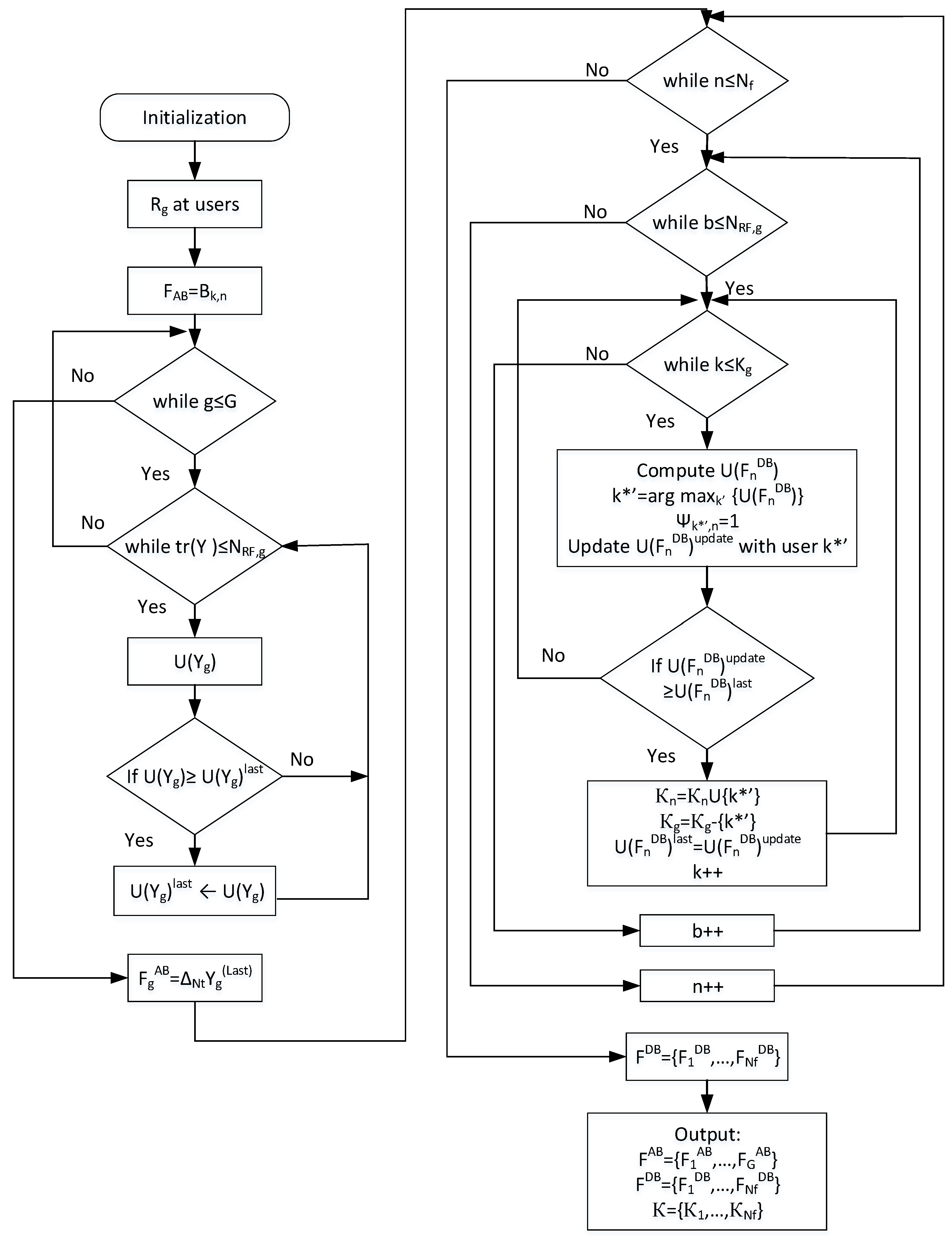
Second, a low complexity suboptimal solution is provided for the optimization problem. The algorithm generates the analog beamforming matrix, digital beamforming matrix, and the set of users in each group. The DFT/eigenmodes-based analog beamforming is formed using limited statistical CSI feedback from the users. Then, the digital precoder design with users selection is done iteratively.
Finally, we develop a K-Mean algorithm based unsupervised machine learning scheme for users grouping. These users groups are used to form the limited feedback (statistical channel state information) based analog beamforming matrix. The proposed machine learning based analog beamforming along with the zero-forcing digital precoding and user scheduling gives better performance than the DFT/eigenmodes-based solution.
The rest of the paper is organized as follows. System, signal, and channel model along with the problem formulation are described in
Section 2.
Section 3 introduce the relaxed-convex transformation of the formulated mixed integer optimization problem. Suboptimal solution to the joint resource allocation and hybrid beamforming based on eigenmodes and discrete Fourier transform is given in
Section 4.
Section 5 proposes machine learning based users grouping and beam selection for joint optimization problem. Simulation results are given in
Section 6, followed by the conclusions in
Section 7.
Notations: Bold upper and lower case letters denote vectors and matrices, respectively. The notations , , , , and denote the inverse, pseudo-inverse, transpose, Hermitian transpose, and trace of a matrix . is a vector operator, is diagonal matrix, and ⊗ is the Kronecker product. denotes the Frobenius norm. The identity matrix is denoted by . represents the expectation with respect to the random variable within the brackets.
2. System Model
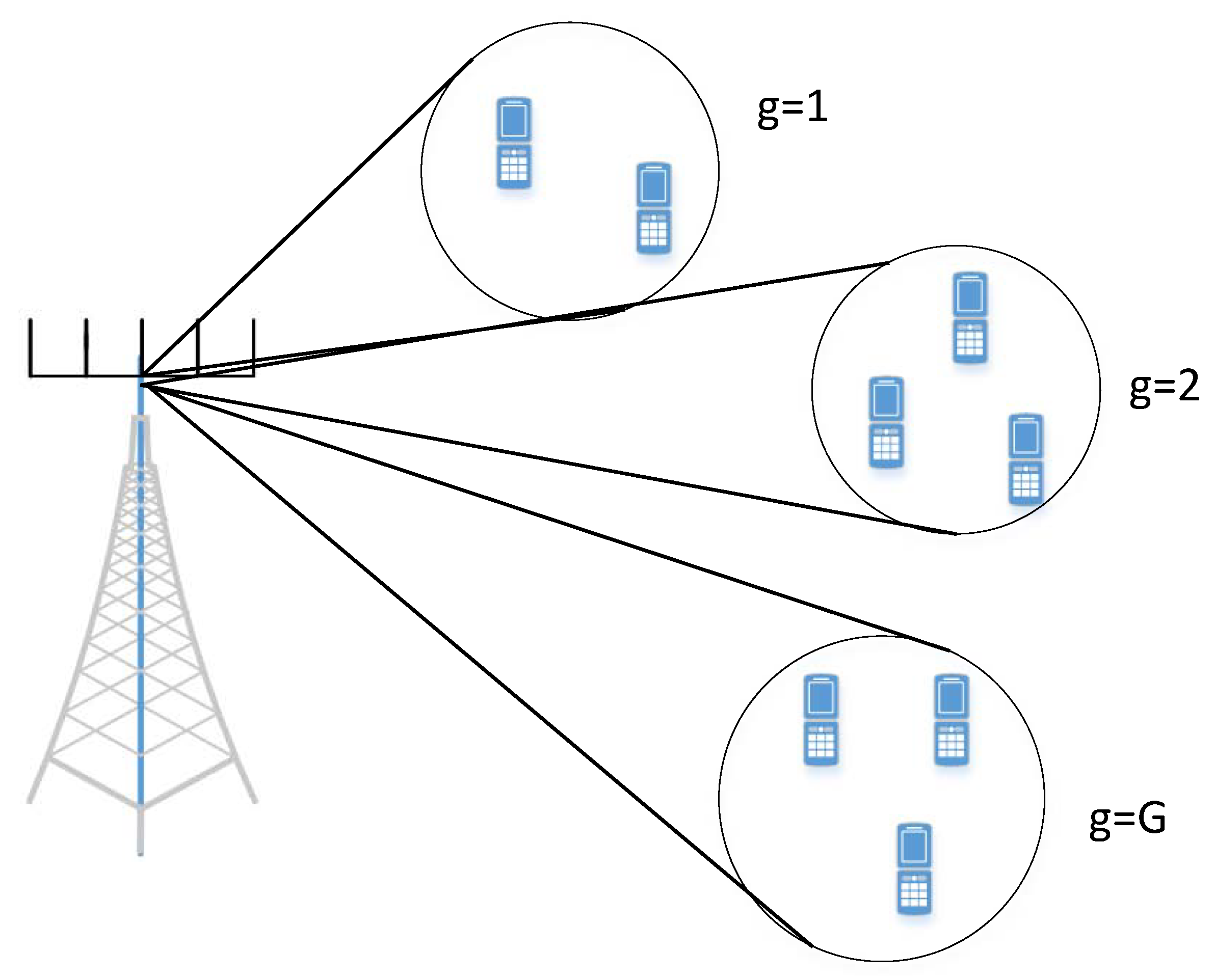
Consider a FDD MU-MIMO downlink system where a base station (BS) with
antennas is located at the cell center and transmits to
K single antenna users as shown in
Figure 2. There are
G groups of users such that the group
. Each group contains
users.
Assume that the BS and users have the knowledge of the channel. We consider multi-carrier OFDM transmission with narrow-band blocK-fading channel. The BS is equipped with
antennas in linear antenna array (ULA) configuration. The information signal block
at the input of the BS transceiver for the user
k is given as
and for the subchannel
n,
where
and
are the number of subchannels and the number of symbols per subchannel, respectively. In a subchannel
n, the information symbol vector is
. We assume
, such that the transmit signal per subchannel
n satisfying
, where
is the transmit power per subchannel and
is the total transmit power of the BS. The transmit signal vector
is obtained from
, where
is the precoding matrix. The hybrid beamforming divides the precoding matrix into baseband digital precoding matrix
and RF analog precoding matrix
, where
is the number of RF chains as shown in
Figure 3. The transmit signal
is given by
Also, the precoding matrix must satisfy
since
, therefore,
The transmit signal in subchannel
n is
. Thus, the received signal vector
at
K users in subchannel
n is given by
where
is the channel matrix with
being the channel vector from BS to user
k in subchannel
n,
, and
be the additive white Gaussian noise (AWGN) in subchannel
n at the users. The RF beamforming
is performed in time domain and the same beamforming is applied on all subchannels, whereas, the digital beamforming
is performed in frequency domain on the per subchannel basis [
11]. In the
subchannel, the
UE receives the sum of all transmitted signals for
K UEs over its MIMO channel
as
where
is the
channel vector. We denote the rank of the channel matrix
by
, where
. In matrix form, the above equation is given as
The
received signal at the
UE is given by
Combining the signals for all UEs in a
K dimensional received signal vector
, we get the system equation as
where
.
2.1. Channel Model
Generally, massive MIMO channel models are categorized in two types (i) analytical models and (ii) physical models [
4]. Analytical models are commonly used for the theoretical analysis of wireless communication systems. The most commonly used analytical model is Kronecker channel model. It is a correlation-based model and characterizes the MIMO channel matrix in terms of the separate transmit and receive side spatial correlation matrices [
24],
under the above assumptions, the channel model
is simplified to Kronecker model,
where
is an i.i.d. unit variance MIMO channel matrix,
and
are the transmit and receive corrrelation matrices, respectively. The transmit and receive correlation matrices are given as [
24],
The physical models explicitly model wave propagation parameters like the complex amplitude, DoD, DoA, and delay of an MPC [
24,
25]. MmWave propagation leads to limited spatial scattering due to the high free-space pathloss. In addition, the large tightly packed antenna arrays lead to high levels of antenna correlation. The sparse scattering and antennas spatial correlation makes many of the commonly used statistical fading distributions inaccurate for mmWave channel modeling. Therefore, we use extended Saleh-Valenzuela model, which accurately describes the mathematical structure present in mmWave channels [
26,
27]. For simplicity, we assume that each scattering cluster around the transmitter and receiver contributes a single propagation path [
28].
In general, the mmWave MIMO channel matrix between the BS with
transmit antennas and a user
k with
receive antennas in subchannel
n, can be modeled as double directional channel,
where
L is the total number of multipaths,
is the complex gain of the
path with i.i.d.
, and
is the distance dependent pathloss between the BS and user
k[
29]. The LOS path is included with
. Moreover,
and
are the receive and transmit steering vectors, respectively. The variables
and
are the
path’s azimuth angles (boresight angles in the receive array and transmit array) of arrival and departure, respectively. The steering vectors are given by
The elements of transmit and receive steering vectors are given by
where
is the wavelength,
,
is the beamforming delay, and
and
are the antenna spacing at the transmitter and receiver, respectively.
The channel matrix in (
14) can also be written in more compact form as
where
and,
and
consist of stacked steering vectors of AoA and AoD, respectively, i.e.,
and
. The matrix
is a diagonal matrix, given as
. The small scale fading at user
k in subchannel
n in multipath component (MPC) is given by
with zero mean and variance
. Assume that each MPC is i.i.d. such that
. We can express the channel model in (
19) as
where
and
with
such that
and
.
Substituting (
20) in (
13) and averaging over small scale fading, we get the transmit and receive correlation matrices for user
k in the subchannel
n as
For mmWave massive MIMO systems with large number of antennas, the steering vectors are asymptotically orthogonal to each other [
6]:
Moreover, in mmWave massive MIMO, acquisition of the instantaneous full CSI is not practical. Instead, an average CSI in terms of
,
, and
is a practical solution for the beamforming design because the coherence time of the channel statistics based CSI is of the order of few seconds or more as compared to the small scale of the order of milli-second [
6].
2.2. Problem Formulation
The hybrid beamforming divides the beamforming matrix into two parts: covariance-based pre-beamforming matrix
realized by analog beamformers and the reduced dimension MU-MIMO digital precoding based on the effective channel
(omitting the subchannel subscript for simplicity). We assume that
K users are divided into
G groups, such that, the group
g contains
number of users. Since users are near the ground level and surrounded by the scatterers compared to the scatterer-free elevated base-station, we assume one-ring model [
1] and all users in group
g experience the same azimuth center angle (
) and angular spread (
). In this case,
in (
12), therefore, the channel covariance matrix of each user in group
g is given by [
30]
for which the eigenvalue decomposition gives
where
is a tall unitary matrix (
) comprises the eigenvectors of
and
is diagonal matrix with
nonzeros positive eigenvalues along the diagonal. The
element of covariance matrix
represents the correlation between the channel coefficients antenna element
i and
j as
where
d is the distance between antenna elements of ULA and
is the wavelength of carrier frequency. Using the Karhunen-Loeve representation, the channel vector of user
k in group
g is given as
where
and
is beam domain channel. For large
,
tends to discrete Fourier transform (DFT) matrix
[
31]. Each column of
represents one direction of angle-of-departure (AoD), i.e., a
beam.
Alternatively, for the case, when dominant eigenvalues
, then, the channel matrix can be written as ([
13], Equation (5))
The limited feedback-based hybrid beamforming consists of analog pre-beamforming matrix
responsible for spatial group formation and inter-group interference mitigation; and the digital multi-users precoding matrix
for spatial multiplexing inside the group and inter-user interference mitigation. Here,
is the number of RF chains for group
g such that
and
is the number of multi-carrier information symbols vectors for group
g with
and
. The overall analog pre-beamforming matrix
is given by
and the overall digital beamforming matrix
is given by
and the overall channel matrix
where the channel matrix of group
g is defined as
.
The analog pre-beamforming
is based on the slowly varying channel covariance matrix
and can be implemented by the DFT matrix (when
is large), whereas, the digital beamformer
is based on the instantaneous channel information of the reduced dimension effective channel
. The overall effective channel is given by
The excessive pilot transmission in downlink and feedback in uplink of FDD system can be reduced by only sending the group-wise average CSI based channel estimates in uplink. This is accomplished by using the diagonal elements
as feedback information with the size of
for
. The analog pre-beamforming is designed in such a way that the other elements of matrix (
32)
for all
. This group-wise division creates virtual sectors, each group corresponds to a virtual sector [
30].
The second order channel statistics-based RF beamformer
remains the same across multiple coherence blocks which gives the effective instantaneous channel between BS and user
k as
with
. Therefore, channel statistics-based CSI sufficiently reduces the feedback overhead on each user, otherwise, for instantaneous CSI, each user have to send the
size of channel estimate on the uplink channel. The covariance of effective channel
is given by using (
13) as,
The analog beamformer consists of columns of the DFT matrix, which can be easily implemented by phase shifter network. Therefore,
can be obtained by eigenvalue decomposition of channel covariance matrix. With the group-wise hybrid beamforming, the received signal
for group
g in subchannel
n becomes
and the received signal of user
k in group
g in subchannel
n is given by
The received signal to interference and noise ratio (SINR) at the user
k in group
g and subchannel
n is given by
The spectral efficiency of user
k in group
g and subchannel
n is expressed as
where
is the binary variable such that it is equal to 1 if user
k is selected in group
g in the subchannel
n. In order to achieve balance tradeoff between throughput and fairness [
32], we use proportional fairness (PF) based throughput maximization. We define per user proportional fairness metric as
where
is average throughput (moving average) over a past window of length
[
33], as
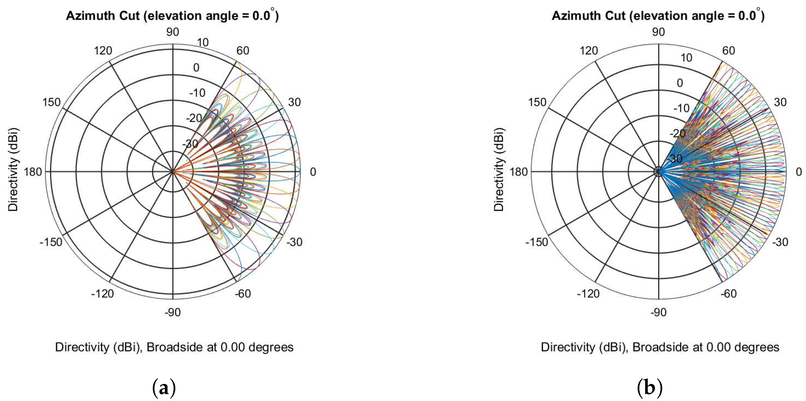
The large number of antennas in massive MIMO systems enable the use of the eigenmodes of the channel covariance matrix, i.e.,
comprises of the columns of the DFT matrix [
6]. DFT-based beams with
and
are shown in
Figure 4a,b, respectively.
The beam steering matrix
consists of selected columns of
DFT matrix
such that
where
consisting of all eigenmodes and
is an
binary beam selection matrix, with
is the rank of the channel covariance matrix. The selection matrix
with only a single one on each row and column such that
. Now we formulate our optimization problem for joint spatio–radio resource allocation and precoders design with the objective to maximize the utility function as
The above optimization problem is a mixed integer programming (MIP) problem with coupling between the digital and RF precoders in the power constraint. This MIP problem is NP-hard [
14].
3. Relaxed-Convex Transformation
Though the above MIP optimization problem is NP-hard, it can be transformed to a relaxed convex optimization problem by (i) relaxing the binary integer constraints to real number between 0 and 1 [
14], and (ii) decoupling the digital and analog precoders. For decoupling purpose, we make use of change of variables
, where
is the
equivalent digital precoder [
34]. Thus, the problem in (
42) can be written as
For a given RF precoder
and the knowledge of perfect CSI at the base-station, the digital precoder can be obtained by conventional MU-MIMO techniques, e.g., the
zero-forcing and
block diagonalization [
15].
For the digital precoder, we adopt the ZF precoder for no multiuser interference among the users in each groups. The beamforming vector of user k is chosen to be orthogonal to the effective channel vectors of all the other users in the group. Zero-forcing is a suboptimal but low complexity approach within the linear precoders’ class. ZF precoder is asymptotically optimal among all downlink beamforming techniques in high SNR region. It guarantees high spectral efficiency for large-scale antennas with low-complexity linear processing [
35]. For
, it has shown that zero-forcing beamforming can achieve up to
of the non-linear dirty paper coding (DPC) capacity [
36]. In order to make this paper self-contained, we describe the block diagonalization briefly. Since digital precoder is used to mitigate the multiuser interference within a groups and all groups are independent, we omit the subscript
g. First we consider the downlink transmission over one subchannel
n with the general case of BS with
antennas and
users with
antennas each, such that
. The downlink channel on the subchannel
n is expressed as
matrix,
For user
k, we define the following
channel matrix
Let the rank of
be denoted by
, then the nullspace of
has dimension
. Performing the SVD of each user’s channel matrix in subchannel
n leads to the following
where
and
are the unitary matrices. The columns of
are the left singular vectors of
, the columns of
are the right singular vectors of
, and
is a diagonal matrix in which the diagonal entries are the singular values of
. In the last equality of (
46),
holds the first
right singular vectors of
and
contains the
singular vectors of
which are in the nullspace of
. The columns of
are best suited for user
k beamforming matrix
, because they will provide zero interference at other UEs. Usually
contains more number of columns than the
, therefore we use some linear combinations of the columns of
to make at most
columns.
where
gives the matrix with columns as the linear combinations of the columns of
. The right hand side of the equation is the SVD of
, where
is
diagonal matrix and
represents the
singular vectors with nonzero singular values of
. The Equation (
47) can also be written as,
The transmit beamforming matrix that maximizes the user
k throughput without any inter-user interference is obtained as,
The transmit digital beamforming matrix for subchannel
n is defined as
where
and
is a block diagonal matrix whose elements scale the power allocated to each interference-free virtual subchannel for all UEs. The receive combining matrix for this user is
[
37].
In the case of single antenna users, complete diagonalization is achieved entirely at the BS by channel inversion, i.e.,
, where
is the pseudo-inverse of
[
38].
where
is a normalization factor chosen to satisfy the power constraint and is given by
Using the definition of the pseudo-inverse, we get,
where
is the regularization parameter,
for ZF precoding and
for regularized ZF, with
. Lastly, introducing the group subscript again, the SINR of user
is given by
and the PF sum rate is calculated as
5. Machine Learning: K-Means Based Optimal Users Grouping for Analog Beamforming
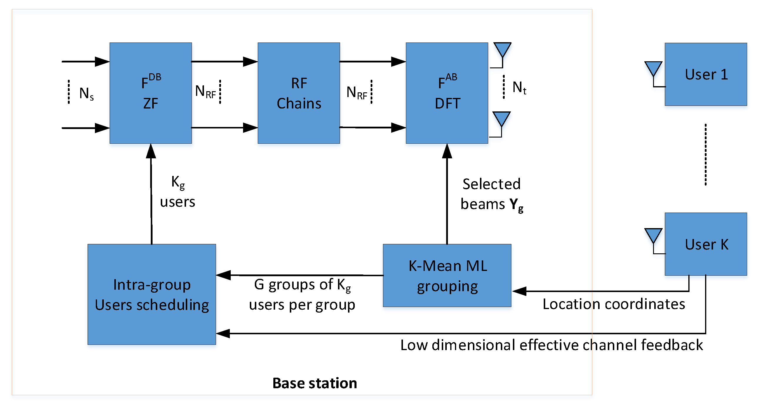
In this section, we use machine learning technique to group the users. Then, the DFT based fixed switched-beams are used to realize the analog beamforming matrix. The joint users scheduling and hybrid beamforming architecture with ML-based users grouping is shown in
Figure 6.
Machine learning algorithms can broadly be divided into two main categories, namely supervised learning and unsupervised learning algorithms. The former class of algorithms learn by training on the input labeled examples, called training dataset, , where the example consists of the instance of feature vector and the corresponding label . Given a labeled training dataset, these algorithms try to find the decision boundary that separates the positive and negative labeled examples by fitting a hypothesis to the input dataset. Unsupervised machine learning algorithms, on the other hand, are given an unlabeled input dataset. These algorithms are used for extracting information or features from the dataset. These features might be related, but not confined, to the underlying structures or patterns in the input data, relationships in data items, grouping/clustering of data items, etc. Discovered features are meant to provide a deeper insight into the input dataset that can subsequently be exploited for achieving specific goals. Clustering algorithms make an important part of unsupervised learning where the input examples are grouped into two or more separate clusters based on some features. The K-Means (KM) algorithm, is probably the most popular clustering algorithm. It is an iterative algorithm that starts with a set of initial centroids given to it as input. During each iteration, it performs the following two steps.
Assign Cluster: For every user, the algorithm computes the distance between the user and every centroid. The user is then associated to the cluster with the closest centroid. During this step, a user might change its association from one cluster to another one.
Recompute centroids: Once all users have been associated to their respective cluster, the new position of centroid for every cluster is then calculated.
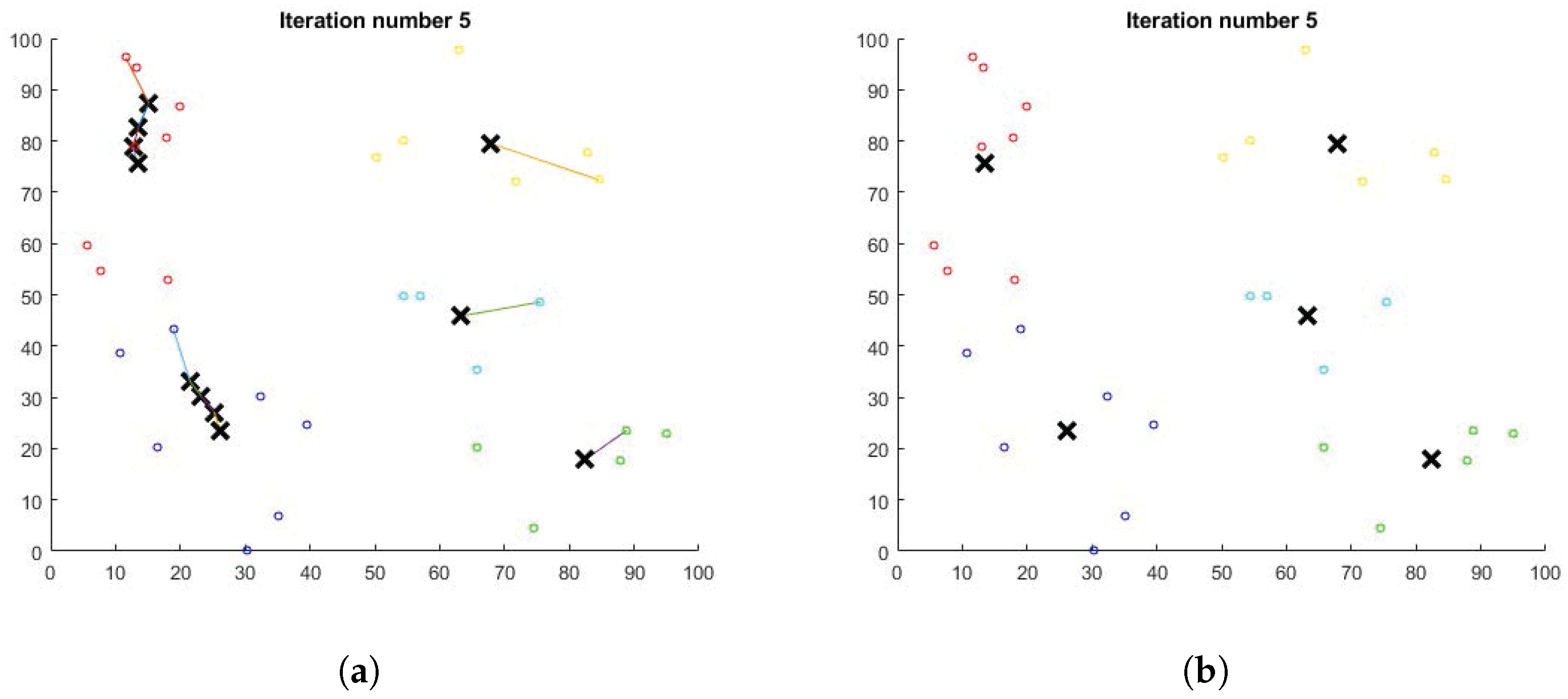
Figure 7a depicts how the cluster centroids keep moving across iterations until the system stabilizes for an example network consisting of thirty users being grouped in five clusters. The system becomes stable in only five iterations and the final cluster layout is shown in
Figure 7b.
Let us define the following notations to be used later in this section.
Now the cost function
J can be defined as
with the following optimization objective function.
It may be pointed out that Equation (
57) allows us to compare multiple clustering layouts based on their cost and select the one with the lowest cost. The above optimization objective function constitutes a non-convex and NP-hard problem because it has many possible local minima and integer optimization variable
. The KM algorithm heuristically optimize this function by alternate minimization method. It iterates between two steps (Assign cluster and Recompute centroids) as described above.
In this section, we use the KM algorithm for optimal clustering of m users competing for resources in a particular cell. The clustering is performed based on their geographic location, thus our input dataset has m vectors , consisting of location coordinates, of ith user. For the sake of simplicity, we assume these users are deployed in a two dimensional area, i.e., a plane and so , i.e., an ordered pair of location coordinates. Our clustering algorithm is summarized in Algorithm 2.
The proposed algorithm takes the location coordinates of m users as input. It also takes two numbers and as additional input. The algorithm outputs the best number of clusters, k, such that , and corresponding members of each cluster. It starts with and randomly selects k user locations as the initial centroids (line 6). It assigns the closest centroid to each user (line 8) and then computes new centroids by calculating the center/average location of all nodes in each cluster (line 11). So, in effect, the location of centroids keeps moving in successive iterations. It repeats the above two steps until the change in centroid positions is zero or negligible. We repeat the test times with a new set of randomly chosen initial centroids every time. During every test, the discovered centroids, corresponding centroid assignment to users, and the cost are saved (lines 14–16) for later comparison. After running the loop for times, we select and store the best k centroids resulting from the test with the lowest cost while discarding the remaining (lines 19–21). The same is repeated for the next value of k, i.e., , until . At the end we have vectors , one for each value of k, the corresponding assignment vector and cost . Finally, we choose the vector having the lowest cost and corresponding assignment vector among stored cases. That is the best number of clusters and corresponding centroids that the algorithm found.
| Algorithm 2 K-Means based users grouping algorithm. |
- 1:
- 2:
fordo - 3:
- 4:
for do - 5:
repeat - 6:
Randomly choose initial k centroids - 7:
for do - 8:
, such that is the centroid closest to - 9:
end for - 10:
for do - 11:
mean of all users/points assigned to centroid - 12:
end for - 13:
until converges - 14:
- 15:
- 16:
- 17:
end for - 18:
- 19:
- 20:
- 21:
- 22:
end for - 23:
- 24:
- 25:
- 26:
|
After the groups formation, BS sends this information to all users, where users use this information to form reduced average statistical CSI. For example, a user in a group of 5, needs to send the average statistical CSI only after of regular feedback interval time.
6. Simulation Results
Consider the downlink of a multiuser massive MIMO single cell with three 120 degree sectors. We neglect inter-sector interference and focus on a single 120 degree sector served by a ULA of isotropic antennas at BS. The users grouping forms virtual sectors inside 120 physical sector.
In simulation, the results are obtained by averaging over 100 drops. In each drop we randomly generate spatial correlation matrices . For each realization of spatial correlation matrix , we simulate 1000 realizations of instantaneous channel .
The joint spatio–radio scheduling and hybrid precoder scheme first forms the users groups and then selects the beams that maximizes the sum-rate through downlink training process. Secondly, it calculates the ZF based digital precoder using low dimensional effective channel feedback from the users.
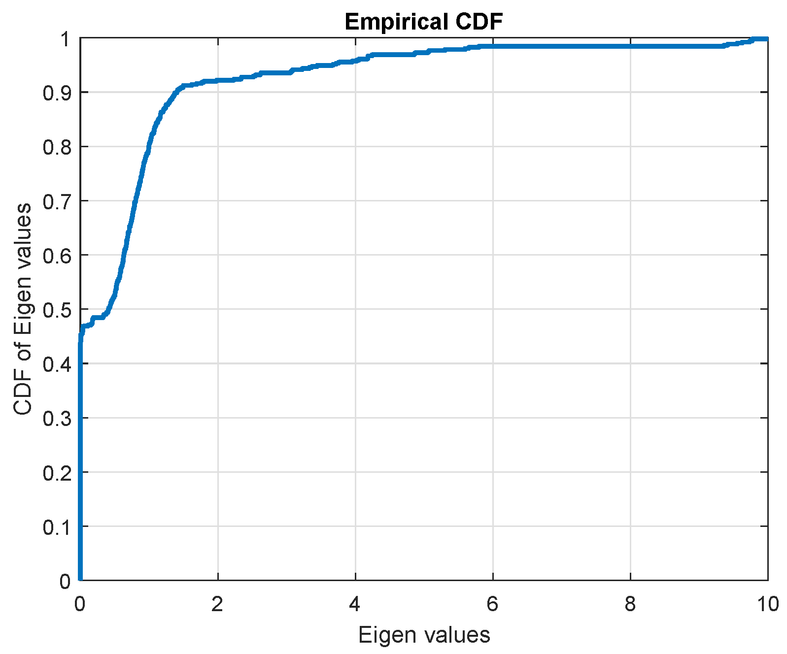
Figure 8 shows the CDF of the non-zero eigenvalues of channel covariance matrix. Notice that approximately
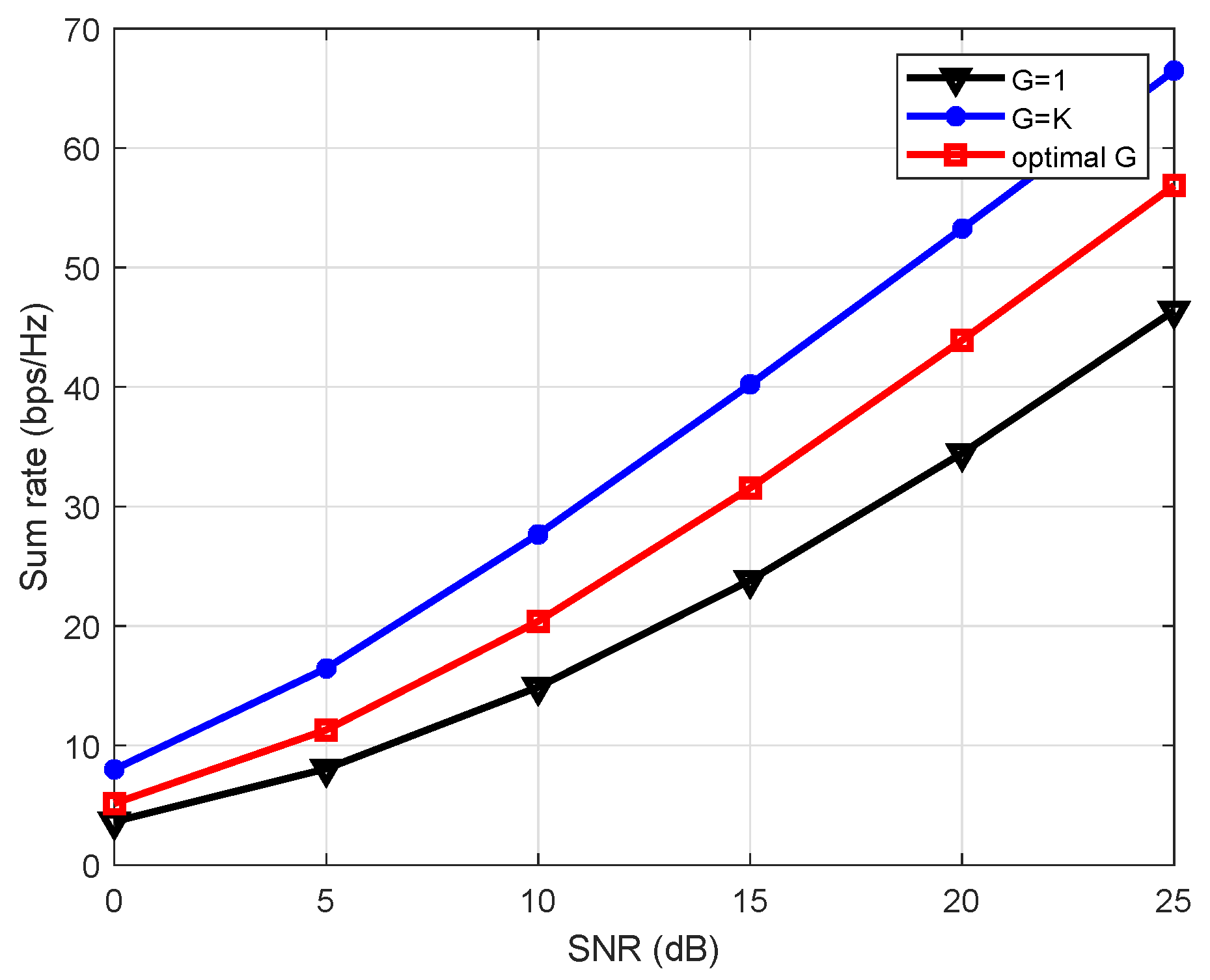
of the non-zero eigenvalues are close to zero. The sum-rate increases as the number of groups increases at the cost of increased feedback overhead as shown in
Figure 9. Using machine learning technique in
Section 5 we can get optimal number of groups from channel covariance feedback. This results in increased sum-rate with substantial reduced feedback. The optimal
gives
increase in sum-rate compared to when
and
decrease in feedback overhead compared to
. The comparison of performance of ML-based users grouping with previous work cannot be provided because there is no previous work that uses ML-based technique to reduce the CSI feedback overhead in massive MIMO systems. Many papers use users grouping in massive MIMO hybrid beamforming [
3,
5,
39,
40], but they do not utilize ML-based users grouping. Therefore, we have compared our proposed solution with two benchmarks of full-CSI (
) and coarse-CSI (
).
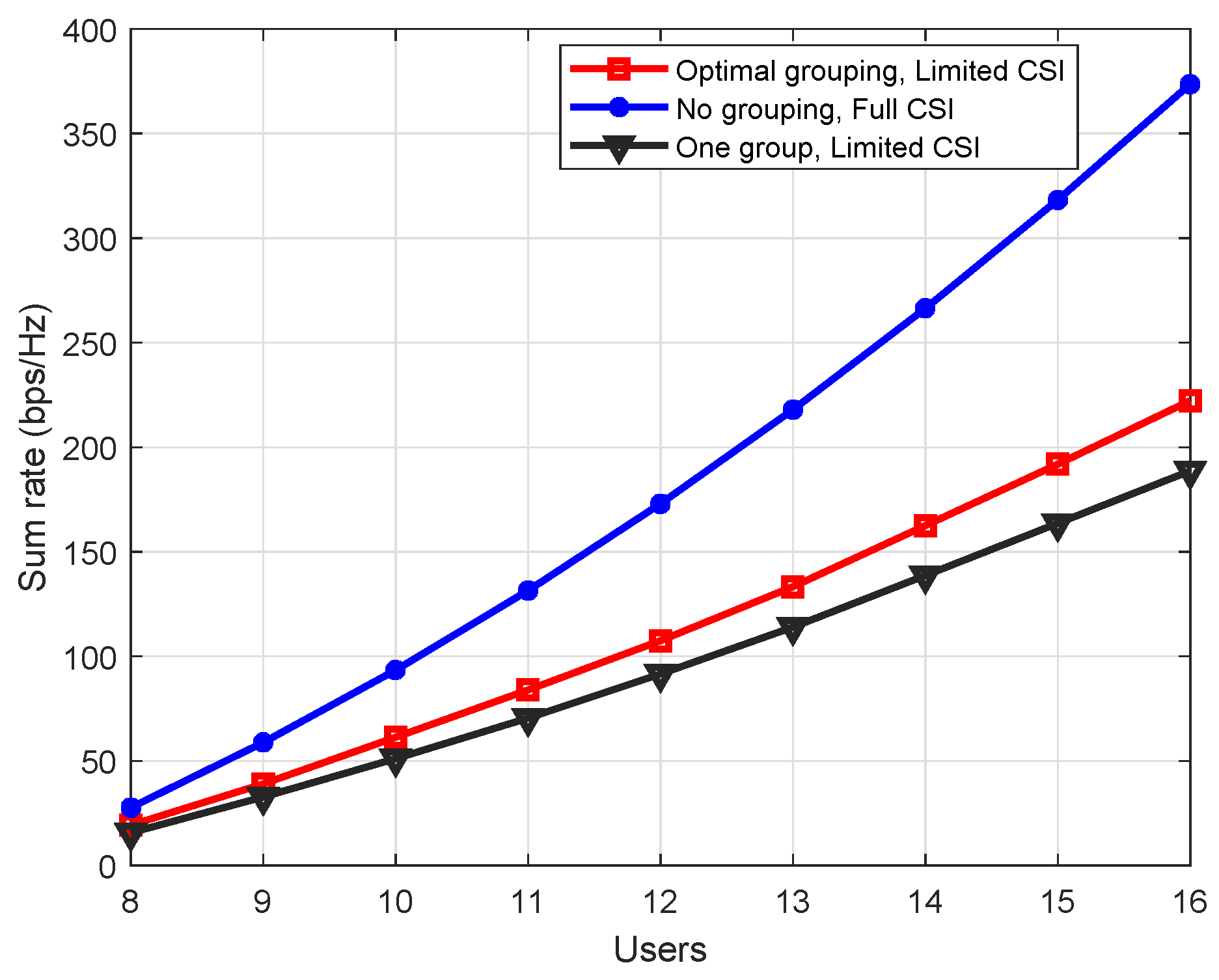
Figure 10 shows sum-rate with number of users at
SNR. For a fixed number of groups
, the increase in number of users, increases number of users per group. Due to the fixed number of groups, the feedback overhead remains the constant. Sum-rate is increasing with users because we assumed
. If we fix the number of RF chains to some hardware limit, then the sum-rate will saturate at specific number of users. It can be seen in
Figure 10, that increasing number of users per group decreases the slop of the sum-rate for limited CSI schemes. This decrease is due the increase in intra-group interference.
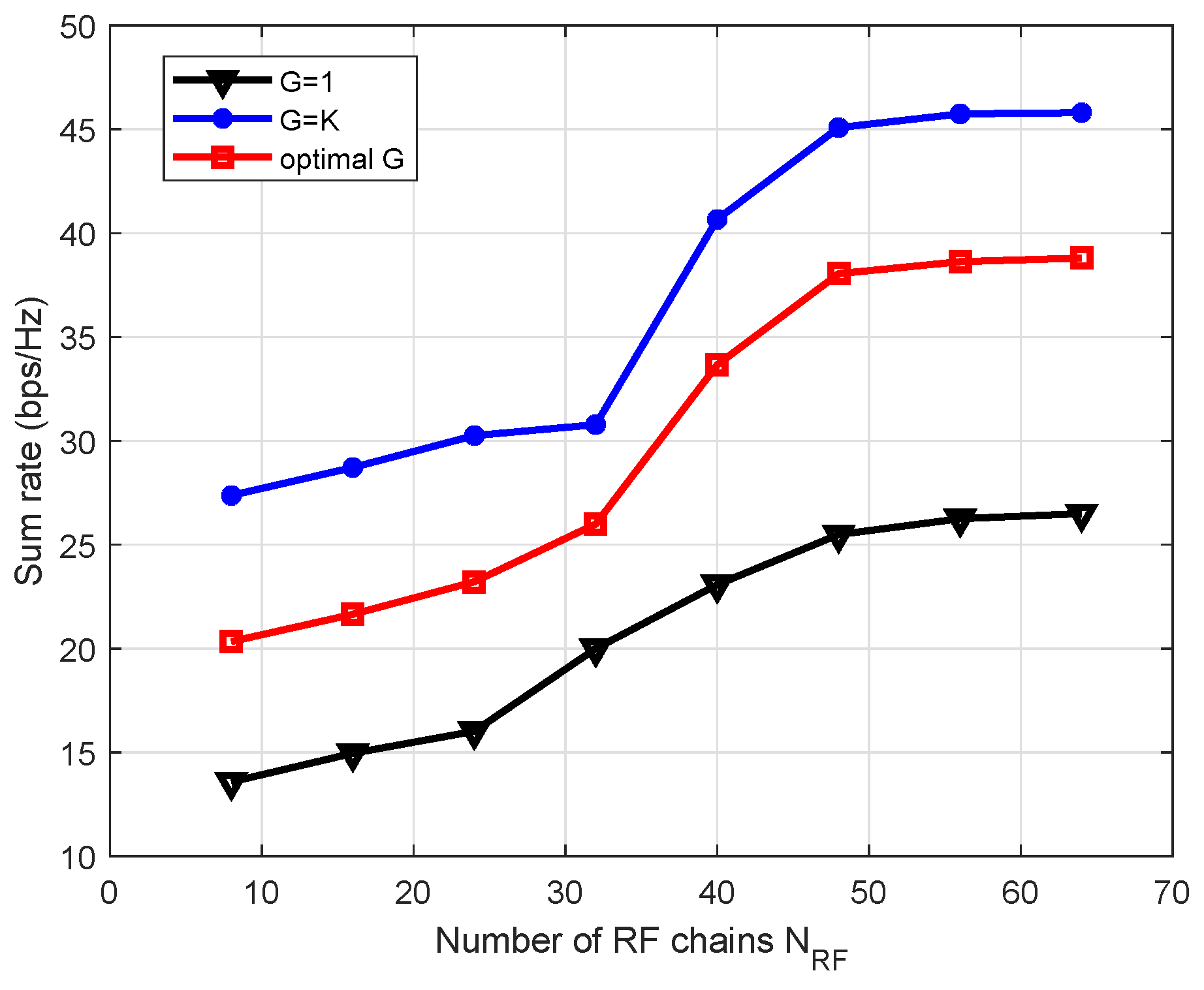
Sum-rate also depends on the number of RF chains but this dependence is not linear as shown in
Figure 11. This figure shows sum-rate variation with number of RF chains
when
,
,
, and
10 dB. Sum rate increases with number of RF chains because it yields better conditioned effective channel matrix. It can be seen that the spectral efficiency does not increase monotonically with
and saturates at
where hybrid precoding is turned to the pure digital precoding. The increase in spectral efficiency with the number of RF chains comes at the cost of higher dimensional effective channel feedback overhead and power consumption in RF chains.
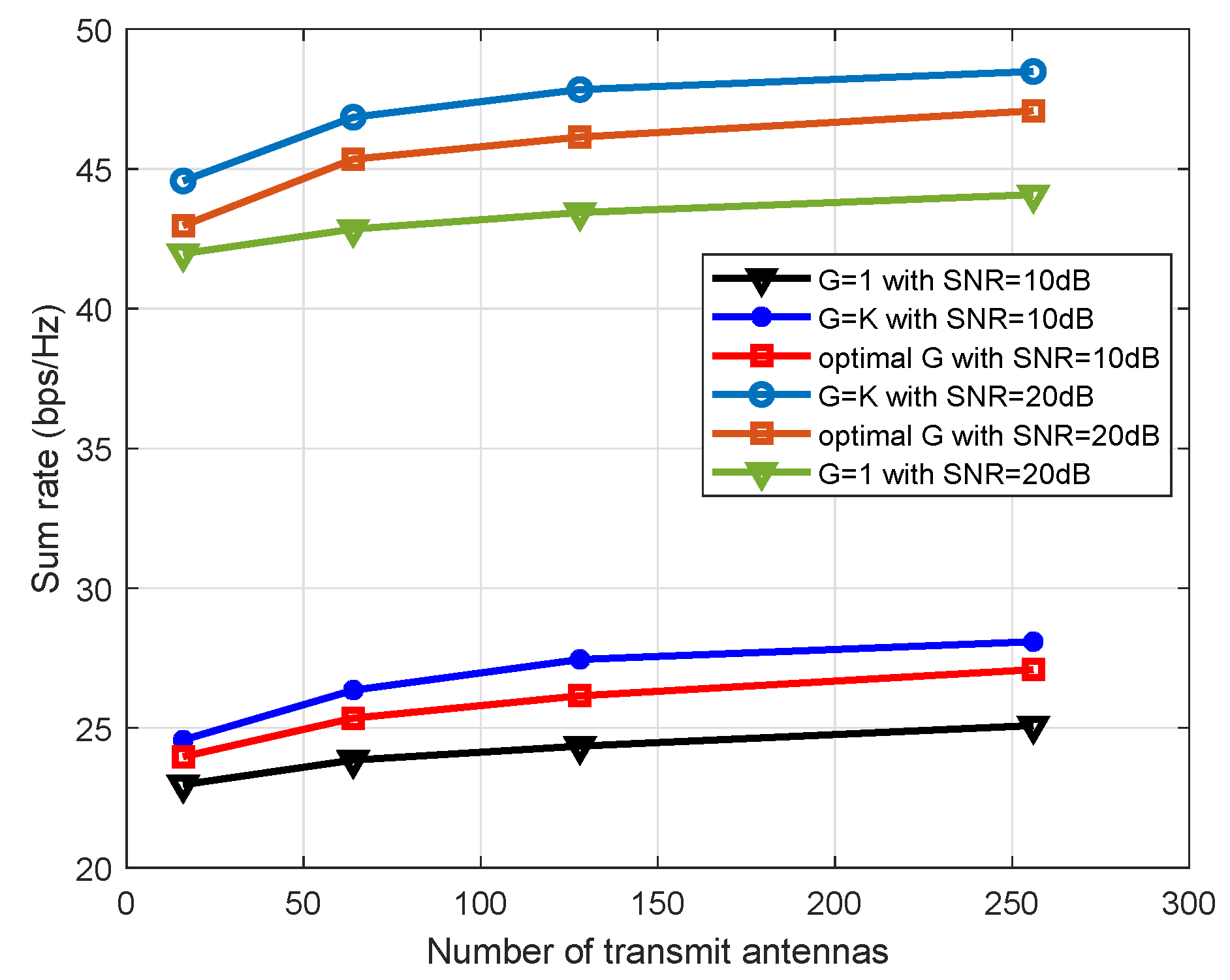
The spectral efficiency of the proposed scheme also varies with number of transmit antennas as shown in
Figure 12. In the figure,
,
dB, and BS has 16, 64, 128 or 256 ULA antennas. The performance gain increases with the increase in number of transmit antennas because large antennas array increases the resolution of the transmit beams (also depicts in figure 4) and, hence, decreases the potential of inter-beams interference.
In general, the spectral efficiency is a function of SNR and for the dB, our ML-based users grouping and hybrid beamforming scheme gives increased sum-rate at the cost of extra feedback overhead as compared to the coarse-CSI case (G = 1). Our proposed scheme incurs reduced feedback at the cost of reduction in sum-rate as compared to the full-CSI case (G = K).
