Article

Efficient Pilot Decontamination Schemes in 5G Massive MIMO Systems

1
Communication Engineering Department, King Abdullah II School of Engineering, Princess Sumaya University for Technology PSUT, Amman 11941, Jordan
2
Department of Electrical Engineering, University of Engineering & Technology, Peshawar 814, Pakistan
3
School of Intelligent Mechatronics Engineering, Sejong University, Seoul 05006, Korea
*
Author to whom correspondence should be addressed.
Electronics 2019, 8(1), 55; https://doi.org/10.3390/electronics8010055
Submission received: 26 November 2018 / Revised: 26 December 2018 / Accepted: 27 December 2018 / Published: 3 January 2019
(This article belongs to the Special Issue Massive MIMO Systems)

Abstract

:
Massive Multiple-input Multiple-output (MIMO) is an emerging technology for the 5G wireless communication systems which has the potential to provide high spectral efficient and improved link reliability and accommodate large number of users. Aiming at the problem of pilot contamination in massive MIMO systems, this paper proposes two algorithms to mitigate it. The first algorithm is depending on the idea of Path Loss to perform User Grouping (PLUG) which divide the users into the center and edge user groups depending on different levels of pilot contamination. It assigns the same pilot sequences to the center users which slightly suffer from pilot contamination and assign orthogonal pilot sequences to the edge users which severely suffer from pilot contamination. It is assumed that the number of users at the edge of each cell is the same. Therefore, to overcome such limitations of PLUG algorithm, we propose an improved PLUG (IPLUG) algorithm which provides the decision parameters for user grouping and selects the number of central and edge users in each cell in a dynamic manner. Thus, the algorithm prevents the wrong division of users in good channel conditions being considered as an edge user which causes large pilot overhead, and also identifies the users with worst channel conditions and prevents the wrong division of such users from the center user group. The second algorithm for pilot decontamination utilizes the idea of pseudo-random codes in which orthogonal pilot are assigned to different cells. Such codes are deployed to get a transmission pilot by scrambling the user pilot in the cell. Since the pilot contamination is generated because different cells multiplex the same set of orthogonal pilots and the pseudo-random sequences have good cross-correlation characteristics, this paper uses this feature to improve the orthogonality of pilots between different cells. Simulation results show that the proposed algorithms can effectively improve channel estimation performance and achievable rate as compared with other schemes.

1. Introduction

With the advent of the era of big data and increasing demand by the explosion of growing numbers of subscribers, the demand for communication networks has exploded, and the existing mobile communication networks (4G) are increasingly unable to meet the needs of users for the network [1]. Massive MIMO is a key technology for 5G wireless communications to increase the spectral efficiency [2,3,4]. It has the ability to be deployed in various communications paradigms such as multicarrier communication, Orthogonal Frequency Division Multiplexing (OFDM) and cooperative communications [5,6,7,8,9,10,11,12]. As massive MIMO utilizes different frequencies in a Frequency Division Duplex (FDD) system. Therefore, the current research on massive MIMO is generally depending on a Time Division Duplex (TDD) system [13], that is, using channel reciprocity to obtain the required channel state information (CSI) [14], but the limited coherence interval limits the number of orthogonal pilots allocated to the user, which inevitably exists. The use of the same pilot by different cell users results in the inability of the Base Station (BS) to distinguish between pilot contamination [15].
In view of the fact that pilot contamination is caused by different cells multiplexing the same pilot, this paper proposes two algorithms for pilot decontamination in massive MIMO systems. The first algorithm is depending on the path loss for performing user grouping (PLUG) while the second algorithm is depending on pseudo-random codes [16]. In PLUG algorithm, the users are divided into a central user group and an edger user group depending on the distance between the users and the BS, and then classified according to the corresponding principle. In the case of a slight loss in the performance of the central user, the communication outage probability of the cell edge user is significantly reduced, and the quality of service (QoS) is significantly improved. On the basis of the PLUG strategy, the improved PLUG (IPLUG) is further proposed, and the decision parameters are dynamically selected to select the number of edge users to realize the dynamic division of the central users and edge users and improve the flexibility of the strategy. The second algorithm is depending on pseudo-random code that assigns different delays to each cell as a code sequence that distinguishes different cells and uses these pseudo-random codes to correspond to the cells. The user pilot performs synchronous scrambling to obtain new user pilots to enhance the orthogonality of user pilots between different cells. At the same time, the mean square error (MSE) of the expected channel estimation under the pilot design scheme is derived and analyzed. The strategy of this paper does not require the large-scale cooperation of BSs. It only needs to know the distance and decision parameters between users and BSs in the current cell and compete for a dynamic grouping by using the division principle. The proposed model has low complexity and requires fewer parameters, which makes it suitable for deploying in massive MIMO systems practical scenarios. It is proved that the proposed pilot design scheme can effectively improve the performance of channel estimation. The numerical simulation results also verify that the proposed pilot design algorithms depending on PLUG and pseudo-random code can greatly improve the performance of channel estimation and effectively reduce the pilot contamination of the system.

2. State-of-the-Art Pilot Decontamination Algorithms

The authors in [8] pointed out that in multi-cell massive MIMO systems, when the number of BS antennas tends to infinity, the performance of the system is mainly limited by pilot contamination, and thereafter the research on pilot contamination in massive MIMO systems has never stopped. The authors in [17] analyzed the influence of pilots on the performance of massive multi-cell MIMO systems and proposed a minimum mean square error (MMSE) multi-cell precoding method. As compared with the traditional zero-forcing (ZF) precoding, the MMSE scheme can significantly improve the gain of the system without pilot contamination, but the pilot contamination is relatively serious. The increase in system gain is limited. In [18], a pilot contamination precoding (PCP) scheme is proposed in which a precoding matrix is designed with ZF to obtain an infinite signal-to-interference plus noise ratio (SINR), but the effect is not ideal when the number of antennas is limited. In [19], the optimal algorithm for finding the optimal pilot contamination precoding matrix and the simple suboptimal algorithm is proposed depending on [18], and the two algorithms are proved to be limited when the number of BS antennas is limited. Compared with traditional MIMO, the gain of the system can be greatly improved. In [20], an intelligent pilot allocation scheme is proposed, which can maximize the uplink SINR of all users in the target cell under the channel of large-scale fading characteristics. The authors in [21,22] proposed a pilot power control method, which was successfully used in the classified cell, which effectively reduced the pilot contamination and improved the downlink reachability and rate of the entire system. Pilot contamination is a problem inherent in a massive MIMO system. The method of solving pilot contamination in different situations is not unique.
Ideally, massive MIMO should use Fully Orthogonal Pilot Scheduling (FOPS) to assign orthogonal pilots to each user, but the length of the pilot sequence and the pilot set size are limited by the channel coherence time. In a typical scenario, the maximum number of orthogonal pilot sequences in a 1ms coherence time is about 200 [23]. Therefore, a massive MIMO system generally adopts Fully Reused Pilot Scheduling (FRPS). Since the pilot between users is non-orthogonal or identical, pilot contamination is unavoidable [16]. When the number of BS antennas tends to be infinite and there is no cooperation, the main factor affecting the system performance is inter-cell interference (ICI) caused by pilot contamination [23], so pilot contamination is critical to the performance improvement of massive MIMO systems.
At present, massive MIMO pilot decontamination is mainly carried out from three aspects: channel estimation method [24,25,26,27,28], matrix precoding method case [29,30], and pilot allocation strategy [21]. The authors in [25] utilize a diagonal Jacket matrix for pilot reduction which has low complexity, excellent eigenvector and a constant diagonal treatment and an energy harvest. The drawback of such a method is that it assumes perfect multipath fast channel estimation. In [26], the authors propose a pilot mitigation algorithm using a low-rate coordination between cells during the channel estimation phase itself. The coordination makes use of the additional second-order statistical information about the user channels, which are shown to offer a power way of discriminating across interfering user with even strongly correlated pilot sequences. The authors in [27] propose a highly efficient Discrete Fourier Transform (DFT) based approximation of the Linear Minimum Mean Square Error (LMMSE) estimator for reducing the pilot contamination problem. The authors in [28] propose an eigenvalue-decomposition-based approach to channel estimation, that estimates the channel blindly from the received data. The approach exploits the asymptotic orthogonality of the channel vectors in massive MIMO systems. It also deploys a short training sequence to resolve the multiplicative ambiguity of the received signals covariance. In [29], the authors propose a zero forcing (ZF) time-shifted pilot scheme, which was known to mitigate the pilot contamination effectively using conjugate beamforming. The authors in [30] proposed interreference-cancellation (IC) precoding scheme for pilot contamination mitigation in massive MIMO systems. They investigated the quality-of-service (QoS) guaranteed user-scheduling which is improved by deploying their proposed scheme. The authors in [31] pilot contamination reduction scheme which is dependent on complex exponential basis expansions. The Linear Time-Varying (LTV) channel is estimated and the optimal pilot symbols are derived following the minimum mean square error (MMSE) criterion and it is shown that the optimal pilot strategy is to group consecutive pilot tones together as a pilot cluster and to distribute uniformly all pilot clusters in frequency-domain. Depending on the pilot allocation strategy, the research found that: In [30], under the principle of maximizing Signal Leakage Noise Ratio (SLNR) precoding, the same guidance is adopted for users with small ICI. Users with high frequency and mutual interference user orthogonal pilots to improve the overall performance of the system in the case of pilot contamination. However, the pilot scheduling scheme requires large-scale cooperation between BSs and needs to know the large-scale fading factor of each user. Such a factor is very difficult in a massive MIMO system with its own complex structure. The authors in [32] proposed a pilot allocation strategy depending on power control, which makes the pilot transmit time slots between cells with relatively large crossover gains staggered, but it is not easy to ensure pilot dynamic synchronization of several cells. The choice of mechanism will directly affect the performance of the strategy. The authors in [33] proposed a pilot coordinated allocation scheme, which allocates pilot sequences by identifying pilot usage conditions and selects user multiplexed pilots that are least affected by pilot contaminations, thereby reducing pilot contamination, but inter-cell cooperation to system brings additional burdens and expenses. The authors in [34] proposed an improved strategy depending on soft pilot multiplexing. On the basis of soft pilot multiplexing technology, packet parameters are introduced for secondary grouping, but the path loss factor, shadow fading, and the size of each user need to be known. The parameters such as the scale fading factor are more complicated, and the computational complexity of implementing the secondary grouping is higher.

3. System Model

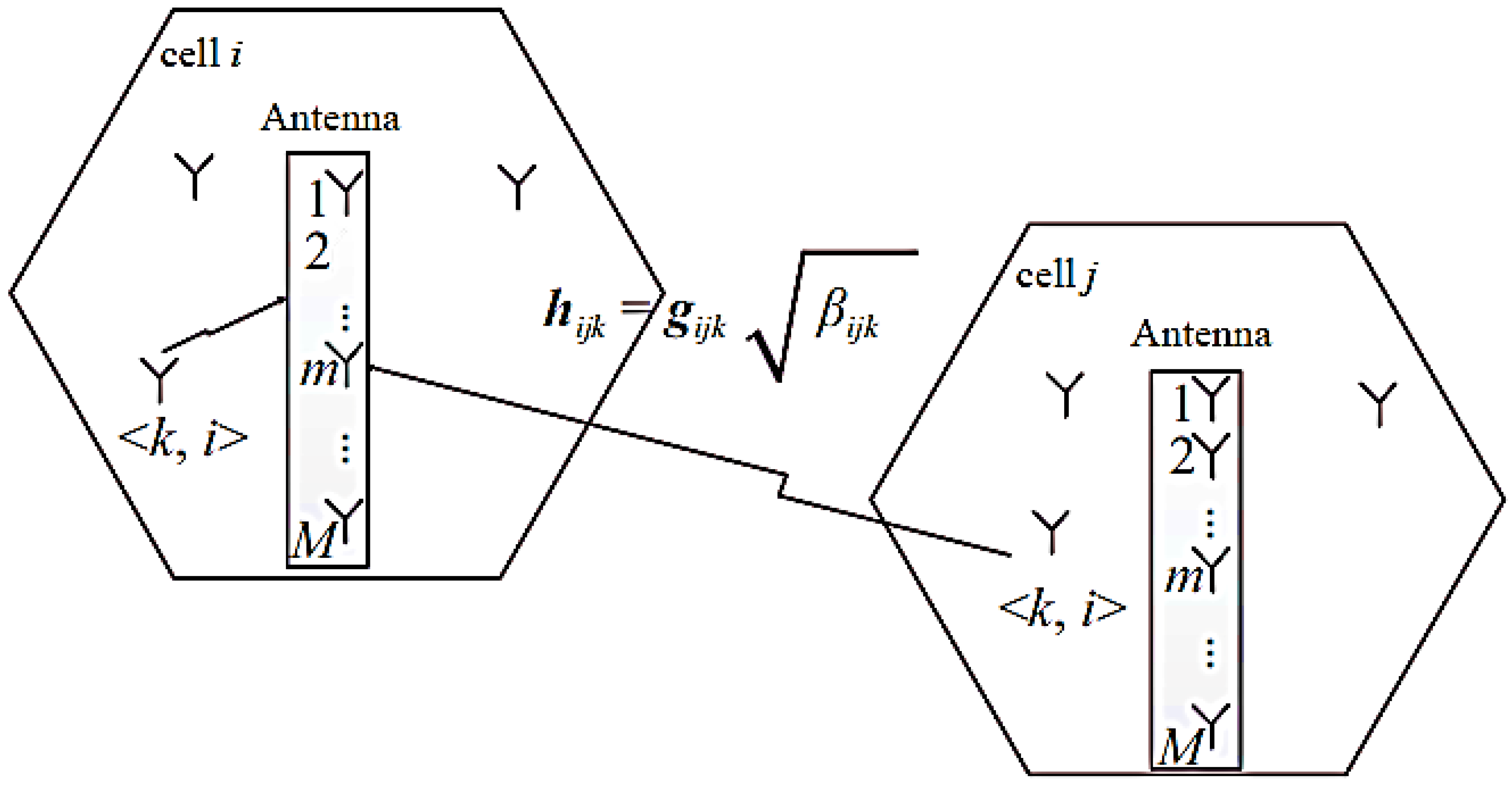
3.1. The System Model

Figure 1 shows the model for massive MIMO system. The channel propagation matrix of all users in the cell to the cell site is:
H i j = G i j D i j
where: G i j = [ g i j 1   g i j 2   g i j K ] , g i j k M × 1 is a small-scale fading vector, each vector is independent of each other and obeys a zero mean complex Gaussian distribution with a variance of I M , that is g i j k   ~ C N ( 0 , I M ) ; D i j = diag ( β i j 1   β i j 2   β i j K ) is a K × K order diagonal matrix, used to describe the j th cell large-scale fading of each user to the i th cell BS, β i j k = z i j k / ( r i j k / R ) α represents the large-scale fading factor of user k to i th BS in the j th cell. Wherein, the shadow fading z i j k obeys a lognormal distribution, that is, 10 lg ( z i j k ) obeys a zero mean, the standard deviation is a Gaussian distribution of σ shadow , R is defined as the cell radius, and r i j k represents the distance from the user k to the i th BS in the j th cell, α represents the path loss factor, and z i j k , r i j k , α are independent of each other. At the same time, it is assumed that the antenna arrays in the same BS are sufficiently compact in arrangement, the large-scale fading of specific users is equal in all propagation paths, but the large-scale fading of different users is independent of each other, and the channel is reciprocity, that is, uplink propagation is assumed to be the conjugate transpose of the matrix in the downlink propagation matrix [22]. For a multi-cell multi-user massive MIMO system, the number of antenna arrays installed by the BS is large, and the channel satisfies progressive orthogonality, namely:
( H i j H H i j M ) = D i j   ( G i j H G i j M ) M K D i j D i j

3.2. Causes of Pilot Contamination

In a massive MIMO multi-cell multi-user TDD system, the BS is estimating the uplink pilot signal by the user in each coherent time and complete signal detection and downlink precoding. At the beginning of each coherence time, all users in all cells simultaneously transmit pilot sequences. At the beginning of each coherence time, all users in all cells simultaneously transmit pilot sequences. Suppose ψ i = ( ψ 1 i , ψ 2 i ,   ,   ψ K i ) T is the K × τ dimension pilot sequence matrix of all users in i th cell ( τ is the sequence length), which satisfies ψ i ψ i H = I K , where I K is the unit matrix of order K × K . Under the FRPS policy, the pilot matrix received by the uplink cell BS is:
y i p = p p ( j = 1 L H i j ψ i ) + n i p
where, p p is the pilot signal transmission power and n i p is the additive white Gaussian noise matrix of order M × τ . After receiving the pilot signal, the BS starts uplink channel estimation. The channel estimation value H ^ i i of the target cell is obtained by using the LS channel estimation introduced earlier which is expressed as:
H ^ i i = 1 p p y i p ψ i H = H i i + j i H i j + 1 p p n i p ψ i H
It can be seen from Equation (4) that the i th cell channel estimation value H ^ i i includes the superposition of the channel propagation matrix of other cells to the target cell in addition to the influence of the target channel and noise, which is pilot contamination.
After the user sends the pilot, all users send data signals to the BS and use the same time-frequency resource. The signal received by the i th cell BS is defined as:
y i u = p u j = 1 L k = 1 K h i j k x j k u + n i u
where x j k u is the transmitted data symbol of user k in j th cell; p u is the uplink user data symbol average transmit power; h i j k represents the channel transmission vector of user k to i th cellBS in j th cell, which is the k th column of H i j ; n i u is the additive white Gaussian noise vector of order M × 1 . The BS uses the channel estimation value H ^ i i of the Equation (4) and the received signal vector y i u , and the MF detects the original data symbol x ^ j k u transmitted by the user k in the i th cell is expressed as:
x ^ j k u = h ^ i i k H y i u = ( j = 1 L h i j k H + v i k H ) ( p u j = 1 L k = 1 K h i j k x j k u + n i u )
where v i k is the column vector of the matrix n i p ψ i H / p p . When the number of BS antennas M approaches positive infinity, it is easy to know from Equation (2) that the channel of the massive MIMO system exhibits progressive orthogonality, and the progressive expression of Equation (6) is:
x ^ i k u M p u ( β i i k x j k u + j i β i j k x j k u   )  
It can be known from Equation (7) that when the BS antenna M , the data symbol x ^ i k u will not be affected by the small-scale fading factor and noise. Therefore, when M , the signal-to-interference and noise ratio (SINR) of the user k uplink received signal in the i th cell can be defined as:
S I N R i k u = β i i k 2 j i β i j k 2
It can be seen from Equation (8) that due to the existence of pilot contamination, the uplink SINR is limited by the large-scale fading factor of the same pilot user in the interfering cell. According to Equation (8), the uplink achievable rate of user k in the target i th cell is given by:
C i k u = ( 1 μ 0 ) E { lb ( 1 + S I N R i k u ) }
where μ 0 is the pilot overhead coefficient for full multiplexing, indicating the spectral efficiency loss caused by the pilot sequence used for channel estimation, when other pilot allocation algorithms are used, the adjustment in Equation (9) is to be appropriately made.

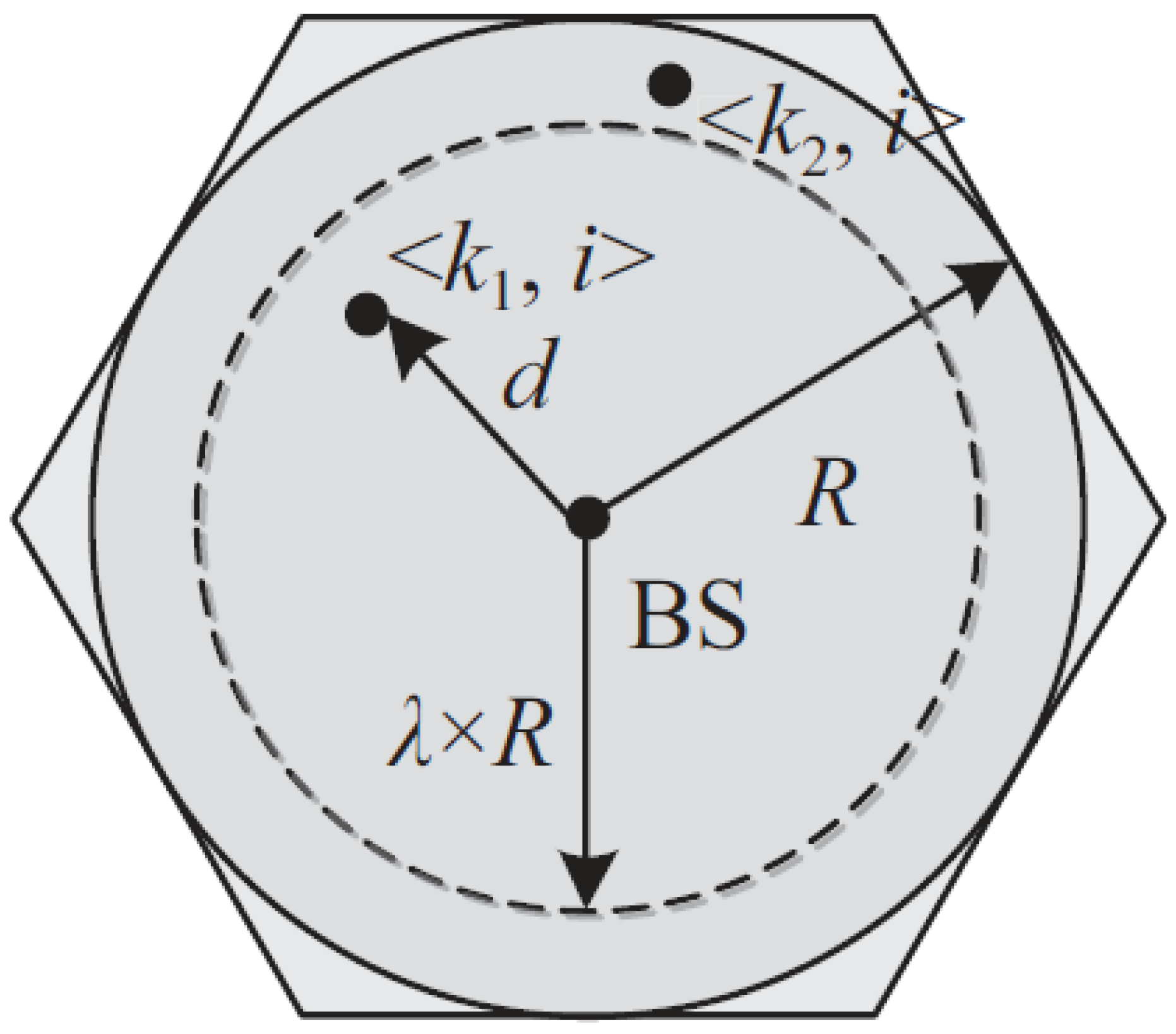
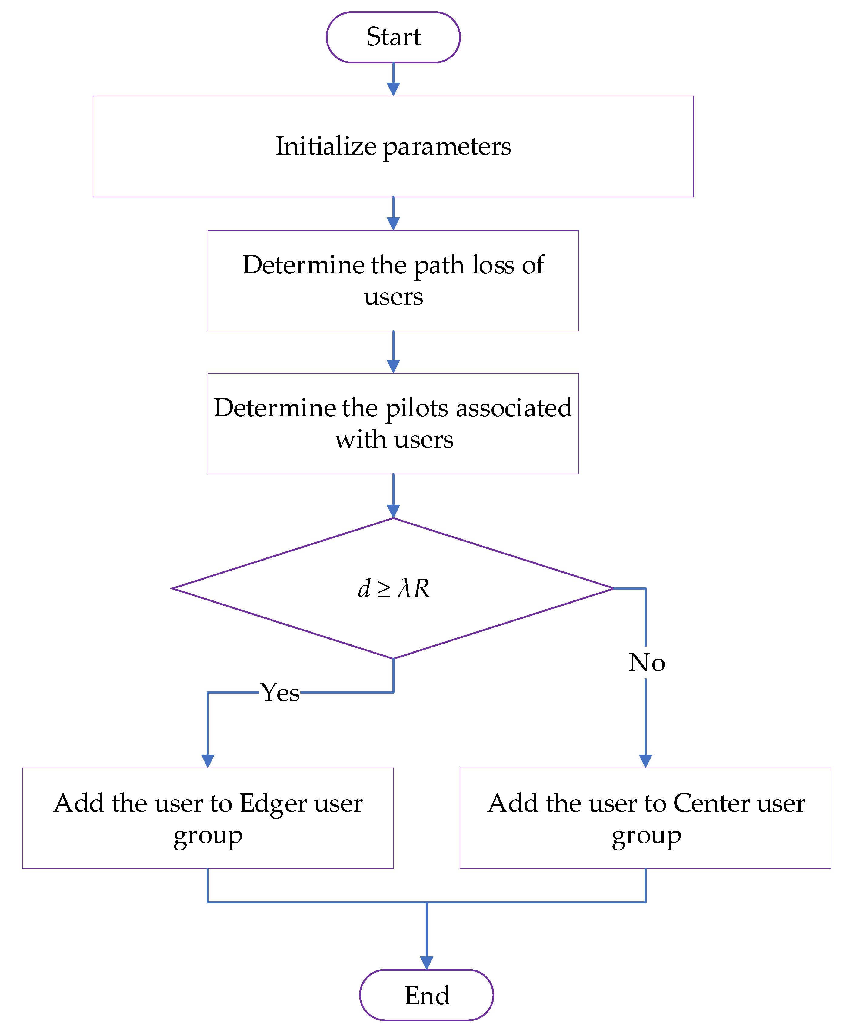
3.3. IPLUG Algorithm

The PLUG algorithm significantly improves the QoS of the edge user but lacks certain flexibility. This is because the number of edge users selected by each cell in the PLUG policy is the same, and only compared with the distance between other users in the cell and the BS. The user’s own specific environment is not considered. Therefore, we proposed an improved pilot scheduling algorithm depending on path loss to perform user grouping (IPLUG) and dynamically select the number of edge users per cell by introducing decision parameters. Figure 2 is a schematic diagram of the IPLUG algorithm decision parameters. The improved IPLUG algorithm is depending on the PLUG algorithm and is designed to improve the accuracy and legitimacy of performing user groupings. In the IPLUG algorithm, when the decision parameter λ is selected, the BS can complete the dynamic grouping according to the user distance d and λ × R . The specific division principle is:
d   ?   λ × R { Y e s Edge   User   N o Center   User
Let the central user set be U c , the edge user set be U e , the central user pilot set be ψ c , and the edge user pilot set be ψ e , the pilot set of j th cell is ψ j = ( ψ 1 j , ψ 2 j ,   ,   ψ K j ) T , j = 1 , 2 ,   L , then:
ψ k i ψ k j H = { 1   ψ k i ψ c   and   ψ k j ψ c 0 otherwise
Then, the pilot vector received by the target i th cell BS is:
y ¯ i p = p p j = 1 L ( k = 1 ,   k U c K h i j k ψ k j + k = 1 ,   k U e L h i j k ψ k j ) + n ¯ i p
For the target i th cell user k , the Least Square (LS) channel estimation is used to obtain the target channel estimation value:
h ^ i i k = 1 p p y i p ψ k i H
Combining Equations (12) and (13), when the number of antennas M the SINR of the central user under the IPLUG algorithm is:
S I N R i k u c = | h i i k H h i i k | 2 j i ,   ψ k i ψ c ,   ψ k j ψ c   | h j i k H h j i k | 2
The edge user is not affected by the pilot contamination, so when M , the edger user S I N R i k u e .
Figure 3 illustrates the flowchart for the IPLUG algorithm.

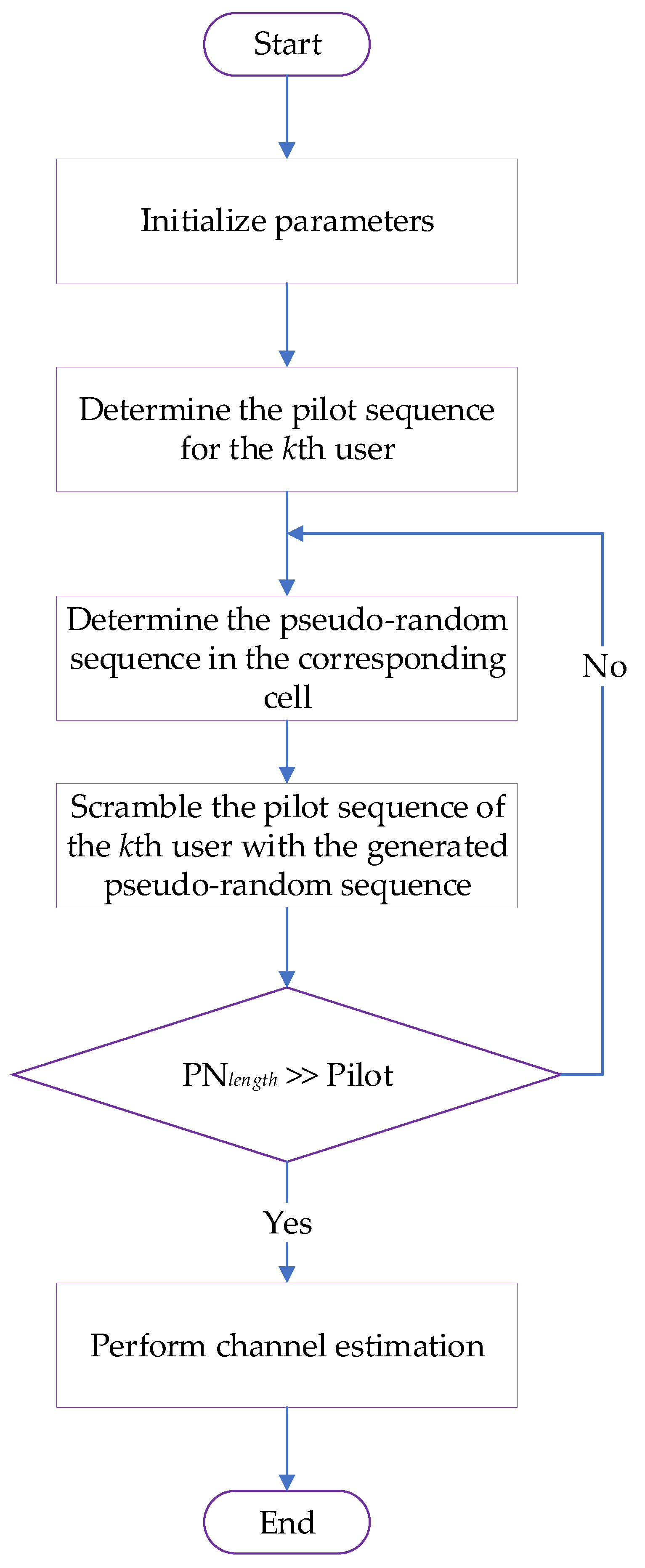
3.4. Pseudo-Random Code-Based Pilot Scheduling

3.4.1. Uplink

Assume that all users in any cell send a pilot sequence of length τ , if the pilot transmitted by K users in the j th cell is ψ j = [ ϕ j 1 ϕ j 2   ϕ j K ] , where ϕ j k τ × 1 is the pilot transmitted by the k th user in the cell ( ϕ j k H ϕ j k = 1 ), when the average transmit power of the user is ρ r , the pilot signal received by the l th cell BS is:
Y l = ρ r τ j = 1 L G j l ψ j T + n l
where G j l = H j l D j l is the channel between all users of the j th cell and the l th cell BS. Let β j l k denote the large-scale fading coefficient of the user k of the j th cell to the l th cell BS, then D j l can be expressed as a diagonal matrix, and the diagonal element is β j l = [ β j l 1 ,   β j l 2 ,   , β j l K ] , n l denotes the additive white Gaussian noise of the l th cell. The term H j l can be determined from the following matrix expression:
H j l = [ h j 1 l 1 h j 1 l M h j K l 1 h j K l M ]
The elements of H j l are independently and identically distributed (i.i.d), and h j k l m represents a small-scale fading coefficient between the k th user in the j th cell and the m th antenna of the BS in the l th cell.
The BS estimates the channel using the received pilot signal, which is known from the standard results in the estimation theory [24]. When the number of BS antennas tends to infinity, the MMSE estimate of the channel is:
G ^ j l = ρ r τ Y l ( I + ρ r τ i = 1 L ψ i D i l ψ i T ) 1 ψ j D j l

3.4.2. Downlink

Considering the BS of the l th cell, it is assumed that the information symbol transmitted by the l th cell to the user is S l = [ S l 1 S l 2   S l K ] T , and A l = f ( G ^ l l ) is a linear precoding matrix of order M × K , where f ( · ) represents a specific linear precoding technique at the BS. After precoding, the signal matrix sent by the BS can be represented as A l S l , and the BS satisfies the average power constraint, that is, t r { E [ A l S l S l H A l H ] } P , then the data information received by the user of the j th cell can be expressed as:
X j = ρ f l = 1 L G j l T A l S l + n j
where ρ f is the downlink transmit power and n j is the AWGN noise of the corresponding cell. Assuming a simple MF precoding technique at the BS, i.e., A l = G ^ l l , Equation (25) can be expressed as:
X j = ρ f l = 1 L G j l T G ^ l l S l + n j = ρ f ρ r τ l = 1 L G j l T ( ρ r τ j = 1 L G j l ψ j T + n l     ) Z S l + n j
where Z = ( I + ρ r τ i = 1 L ψ i D i l ψ i T ) 1 ψ j D j l . When the number of BS antennas increases and tends to infinity then:
1 M ρ f ρ r τ X j ρ r τ l = 1 L D j l   ( ψ l H ψ j + ρ r τ i = 1 L ψ l H ψ i D i l ψ i H ψ j ) 1 D l l S l
It can be obtained from Equation (20) that when all cells multiplex the same set of orthogonal pilots, the right side of Equation (20) can be equated to:
l = 1 L D j l ( I + ρ r τ i = 1 L D i l ) 1 D l l S l
At this time, the signal received by the j th cell will be interfered by the signals transmitted by other cells, especially when the large-scale fading coefficient is large; this phenomenon is called pilot contamination. When all cells use orthogonal pilots, the right side of Equation (20) can be equated to:
D j j ( I + ρ r τ D j j ) 1 D j j S l
In this case, the signal received by the user is a scaling of the signal transmitted by the BS of the cell, and there is no pilot contamination. However, in actual communication, because the coherence interval is limited, it cannot guarantee that all cells can adopt an orthogonal pilot. Therefore, pilot contamination has become an important factor limiting the performance of massive MIMO systems.

3.4.3. Pseudo-Random Code Scheme Description

The pseudo-random code has the similarity of noise sequence. It is a seemingly random but actually regular periodic binary sequence, including m sequence, a Gold sequence, M sequence and combined sequence [35]. Pseudo-random codes have good autocorrelation and cross-correlation properties and can be used as address codes in CDMA communication technology. In addition, thanks to its pseudo-random characteristics, pseudo-random codes are also widely used in information encryption [36]. The pseudo-random sequence is generated by the linear feedback shift register shown in Figure 4, where c i = 0 , indicates that the line is off; c i = 1 indicates that the line is on. The characteristic polynomial of generating a pseudo-random sequence is:
f ( x ) = i = 0 n c i x i = c 0 + c 1 x + +   c n x n
where x i indicates the i th shift register; c 0 = c 1 = 1 , for any i 0 and i n , c i { 0 , 1 } .
Since the pilot contamination is generated because different cells multiplex the same set of orthogonal pilots and the pseudo-random sequences have good cross-correlation characteristics, this paper uses this feature to improve the orthogonality of pilots between different cells. Depending on the above considerations, this paper proposes a pilot design scheme depending on pseudo-random code: in the case that all cells multiplex the same set of orthogonal pilots, the pseudo-random code is used as the code sequence for distinguishing different cells, for each cell allocates a pseudo-random code with different delays, and synchronously scrambles the pseudo-random code in each cell to the user pilot of the corresponding cell to obtain a new pilot.
The pilot design scheme depending on the pseudo-random code is shown in Figure 5. Since the flow of the pilot design of different cells is the same, in order to facilitate the representation without loss of generality, the pilot design scheme is specifically described here. Assume that the pilot of the k th user in a cell is ϕ k = [ ϕ k 1 , ϕ k 2 ,   , ϕ k τ ] T , and the pseudo-random sequence generated by the linear feedback shifter register in the corresponding cell is m = [ m 1 , m 2 ,   , m N ] . The scrambler in Figure 5 indicates that the pseudo-random matrix is multiplied by the matrix of the corresponding user’s pilot matrix. In general, a pseudo-random sequence is a 0–1 bit stream whose length is much larger than the length of the pilot sequence.
In order to ensure that the generated pseudo-random sequence can be used for scrambling, it needs to process as follows:
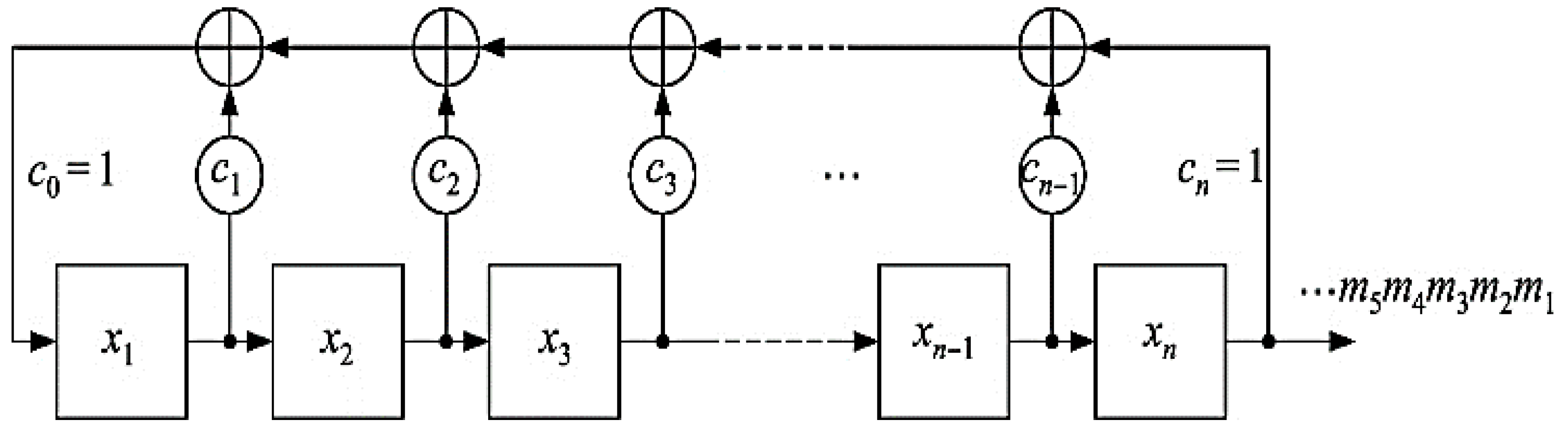
  • The pseudo-random sequence generated by the linear feedback shift register is truncated, and the method is to generate a rectangle depending on the pilot length τ and using a rectangular window for pseudo-random sequences to make truncation.
  • Performing BPSK modulation on the truncated pseudo-random sequence.
  • The pseudo-random sequence is diagonalized after modulation, that is, τ pseudo-random numbers are generated as pseudo-random matrices on the diagonals of the diagonal matrix.
The pseudo-random matrix used for scrambling after the above processing can be expressed as:
P = [ m 1 0 0 0 m 2 0 0 0 m τ ]
After the pseudo-random matrix is scrambled by the scrambler to the user pilot, the pilot of the k th user outputted by the scrambler is obtained as:
Ψ k = P ϕ k = [ m 1   m 2 ϕ k 2   m τ ϕ k τ   ] T
The scrambling method used in this paper is to use the same pseudo-random sequence to synchronously scramble the pilots of all users in the cell, and the pilot of K users in the cell can be obtained after the pilot design as:
Ψ = [ m 1 ϕ 11 m 1 ϕ K 1 m τ ϕ 1 τ m τ ϕ K τ ]
The designed pilot is transmitted to the BS through the channel, and the BS can obtain the required Channel State Information (CSI) by using channel estimation.
When the pilot design is performed on users of other cells, considering the pilot contamination is related to the distance between users, when the distance between two users is large enough, the influence of pilot contamination is neglected. Therefore, the proposed pseudo-random code pilot scheduling scheme only considers the pilot contamination of the target cell and ignores the pilot contamination of the farther cell. Under the above assumptions, only the pseudo-random sequence needs to be allocated to the target cell and the neighboring cell, and the pseudo-random sequence can be reused for the farther cell, which greatly reduces the usage and implementation complexity of the pseudo-random sequence and makes it easy to design a better pilot sequence. Depending on the above considerations, the pilot design of all cells can be designed by using the proposed pilot design scheme. The only difference is that the pseudo-random sequence used by the target cell and the neighboring cell cannot be the same, which involves a pseudo-random sequence selection problem. Since the cross-correlation between different pseudo-random sequences is different, if the cross-correlation value between the selected pseudo-random sequences is large, even if the user pilot is designed, the pilot contamination between the cells is still serious, so that the pilot design seems to be meaningless, so it is necessary to follow the certain criteria when selecting the pseudo-random sequence as the code sequence to distinguish difference cells. Theoretically, the cross-correlation values between pseudo-random sequences are connected. Nearly 0, the effect of the pilot design is more obvious, but the complexity of acquiring these pseudo-random sequences will become very high. In order to obtain the desired effect within a certain complexity range, this paper adopts the following criteria to obtain the required pseudo-random sequence. Assuming that the number of cells requiring different pseudo-random sequences is M , the corresponding M pseudo-random sequences need to be satisfied:
| ρ ( m i , m j ) | i j < γ i ,   j = 1 ,   2 ,   ,   M
where ρ ( m i , m j ) = 1 n k = 1 n m i k m j k , is a function that represents a normalized cross-correlation value between two pseudo-random sequences. γ [ 0 , 1 ] is a constant values indicating the upper limit of the normalized cross-correlation value between any two selected pseudo-random sequences.
It can be seen from Equation (27) that in the case where the pseudo-random sequence used is determined, the setting of the value is an important factor affecting the impact of the pilot design scheme. The smaller the value, the smaller the cross-correlation value between pseudo-random sequences. After the pilot design, the orthogonality of user pilots between different cells is stronger, and the effect of reducing pilot contamination is more obvious. Otherwise, it cannot effectively reduce the pilot contamination. The BS and the user in each cell share a pseudo-random sequence, and the BS can distinguish pilots from different cells by using detection techniques. At the same time, since each cell has the same pseudo-random sequence to scramble a set of orthogonal pilots of all users in the cell, after pilot design, the user pilots in each cell remain orthogonal, and in addition, no additional intra-cell interference will be introduced. Moreover, increasing the pilot length is beneficial to improve the efficiency of the pilot design. This is because the length of the pseudo-random sequence is the same as the length of the pilot, and the longer the pseudo-random sequence, the better the orthogonality between them, so increasing the pilot length is equivalent to improving the orthogonality between the pseudo-random sequences. Thereby, the orthogonality of user pilots between different cells after the pilot design is improved.

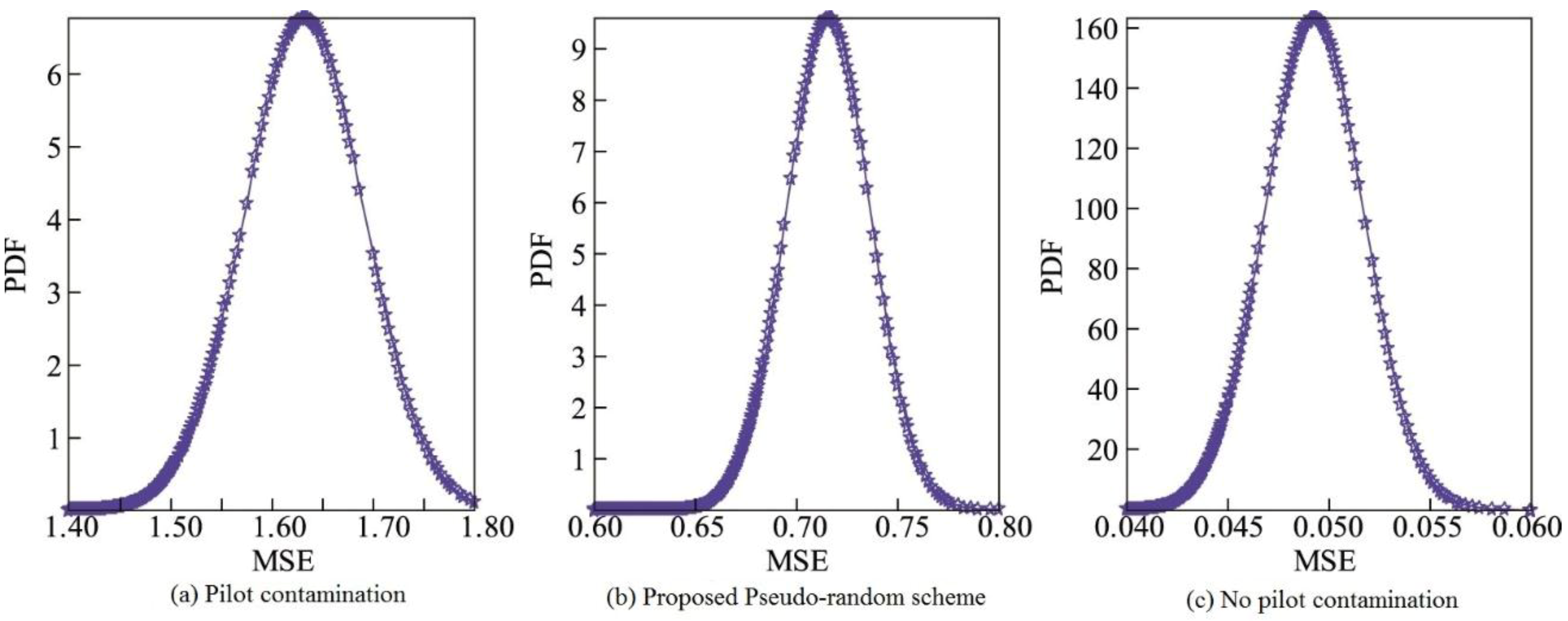
3.4.4. Mean Square Error (MSE) Performance Analysis of Expected Channel Estimation

This section will use the new pilot to derive and analyze the MSE of the channel estimate and explore the pilot design method described in Section 3.3. It can be seen from [15] that when the pilot contamination is relatively serious, the channel estimation performance of the system drops sharply. In this case, even if a complex multi-cell MMSE precoding scheme is applied, the performance improvement of the massive MIMO system is limited. In order to facilitate derivation and analysis, this section only studies simple single-cell ZF precoding and its precoding matrix is defined as:
A l = G ^ l l ( G ^ l l H G ^ l l ) 1 t r [ ( G ^ l l H G ^ l l ) 1 ]
It can be found from (28) that a single-cell ZF precoding matrix can be designed as long as the information of the desired channel is obtained. Therefore, the subsequent derivation and analysis in this section are depending on the estimated expected channel.
As can be seen from Section 3.4, the user pilot of the j th cell is Ψ j = P j Ψ , then Equation (15) can be expressed as:
Y l = ρ r τ j = 1 L G j l Ψ j T + n l = ρ r τ j = 1 L G j l ψ T P j T + n l    
In the case where the number of BS antennas is limited, the MMSE estimation of the desired channel is:
G ^ l l = ρ r τ   Y l   ( C n + ρ r τ i = 1 L P i ψ C i l ψ T P i T ) 1 P i ψ C i l    
where C n = E { n l H n l } , is the autocorrelation matrix, representing the received noise n l ; C j l = E { G j l H G j l } is the autocorrelation matrix representing the channel transfer matrix G j l .
The MMSE defining the expected channel estimation of the l th cell BS is:
M m s e E { | | G ^ l l G l l | | F 2 }
Let R = ρ r τ   ( C n + ρ r τ i = 1 L P i ψ C i l ψ T P i T ) 1 P i ψ C i l , then G ^ l l = Y l R , substituting into (38) we get:
M m s e = E { t r { ( Y l R G l l ) H ( Y l R G l l ) } } = t r { R H E { Y l H Y l } R R H E { Y l H G l l } E { G l l H Y l } R + E { G l l H G l l } }
Using the model shown in Equation (29), there is:
E { Y l H Y l } = C n + ρ r   τ i = 1 L P i ψ C i l ψ T P i T
E { Y l H G l l } = ρ r τ P i ψ C l l
E { G l l H Y l } = ρ r τ C l l ψ T P l T
Substituting Equations (32)–(34) into Equation (35), we can rewrite M m s e as:
M m s e = t r { R H ( C n + ρ r   τ i = 1 L P i ψ C i l ψ T P i T ) R ρ r τ R H P i ψ C l l ρ r τ C l l ψ T P l T R + C l l } = t r { C l l ρ r τ C l l ψ T P l T R } = t r { C l l ρ r τ   C l l ψ T P l T ( C n + ρ r τ i = 1 L P i ψ C i l ψ T P i T ) 1 P l ψ C l l }
Since the matrix P i is a diagonal matrix composed of diagonal elements 1 and −1, and ψ H ψ = I , so ( P i ψ ) H ( P i ψ ) = I can be obtained according to the properties of the matrix conjugate transpose. Using the matrix inversion principle, we can express Equation (36) as:
M m s e = t r { C l l ρ r τ   C l l ( Ψ l T C n Ψ l + ρ r τ i = 1 L Ψ l T Ψ i C i l Ψ i T Ψ i ) 1 C l l }
where Ψ i = P i ψ , i = 1 ,   2 ,   ,   L . When M then:
C l l = E { G l l H G l l } = D l l E { H l l H H l l } D l l = M D l l
C n = E { n l H n l } = M I τ
Substituting Equations (38) and (39) into Equation (37), we get:
1 M M m s e = t r { D l l ρ r τ   D l l ( I + ρ r τ i = 1 L Ψ l T Ψ i D i l Ψ i T Ψ i ) 1 D l l }
When the number of users in each cell is K = 1 , Ψ l T Ψ i = ( P l ψ ) T ( P i ψ ) = γ l i , where γ l i is a normalized cross-correlation value between the pseudo-random code in the l th cell and the pseudo-random code in the i th cell, which can be obtained from equation (27). Assuming that the large-scale fading coefficient D i l = [ β i l 1 ] at this time, then Equation (40) can be simplified as:
1 M M m s e = β l l 1 ρ r τ β l l 1 2 1 + ρ r τ β l l 1 + ρ r τ i l γ l i 2 β l i 1
It can be seen from the results of Equation (41) that when the large-scale fading coefficient and the uplink transmit power are constant and the pilot length is constant, the MSE performance of the channel estimation that can be obtained by applying the pilot scheme depending on the pseudo-random code and it is mainly limited by the cross-correlation performance between the pseudo-random sequences used: when the normalized cross-correlation value between the pseudo-random sequences used is large ( | γ l i | is close to 1), the MSE performance of the channel estimation is relatively poor. When the normalized cross-correlation value between the pseudo-random sequences used is small ( | γ l i | is close to 0), the MSE performance of the channel estimation is better. It can be concluded that if a suitable pseudo-random sequence is selected, the above method is adopted. The proposed pilot design scheme can effectively improve the performance of channel estimation, thus achieving the purpose of reducing pilot contamination. Figure 6 shows the flowchart of the proposed pseudo-random pilot code algorithm.

4. Simulation Results

4.1. Simulation Scenario and Parameters

Taking the MATLAB software (R2017b, The MathWorks, Natick, MA, USA) as the simulation platform, it is assumed that the massive MIMO multi-cell multi-user TDD system includes 7 regular hexagonal cells, as shown in Figure 7.
Table 1 shows the details of simulation parameters which are used for simulation analysis of the proposed pilot decontamination schemes. It is assumed that the antenna spacing is 1 2 times the carrier wavelength, that is, there is a correlation between the antennas, but the correlation is not considered in this paper, and it is assumed that all the antennas are omnidirectional antennas. The number of users in each cell is K = 10 , the user is uniformly distributed in the cell, the pilot length is 128, the path loss factor is 3, the pilot overhead coefficient is μ 0 = 0.05 , the cell radius R = 500   m , and the concentrated antennas is 16 M 1024 , and the lognormal shadow fading is 4 dB (only the last normal logarithmic normal shadow fading is set to 2 dB), and the number of simulations is 2000.
According to the above simulation parameters, the Monte Carlo method is used to simulate the uplink SINR, and the normalized channel estimation MSE and the target cell achievable rate, thereby comparing the performance between the PLUG algorithm, the IPLUG, and the FRPS algorithm respectively.

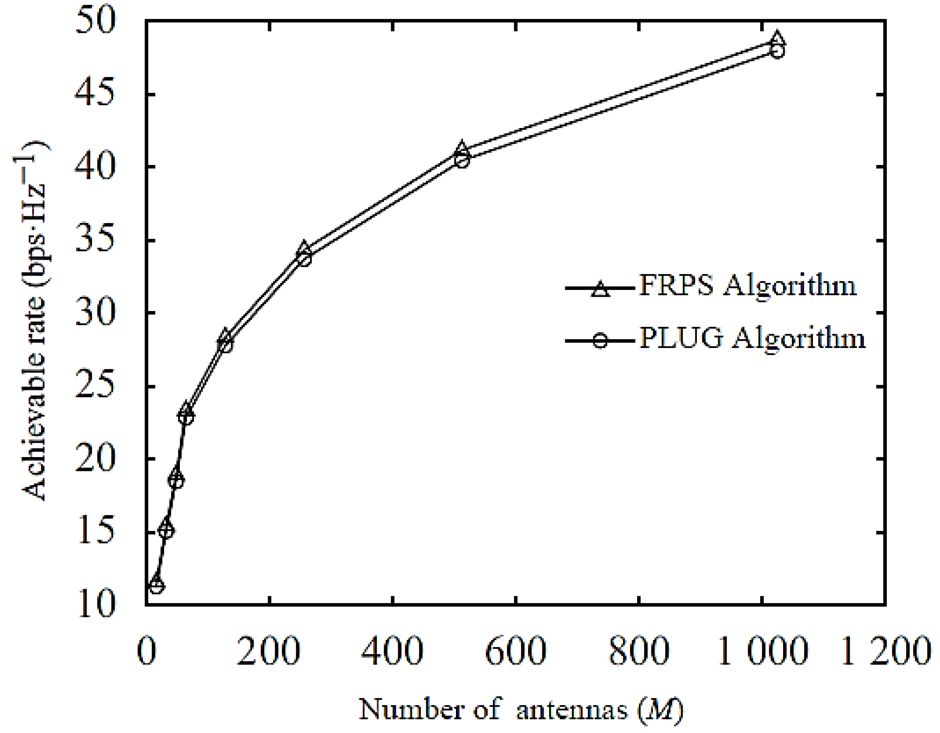
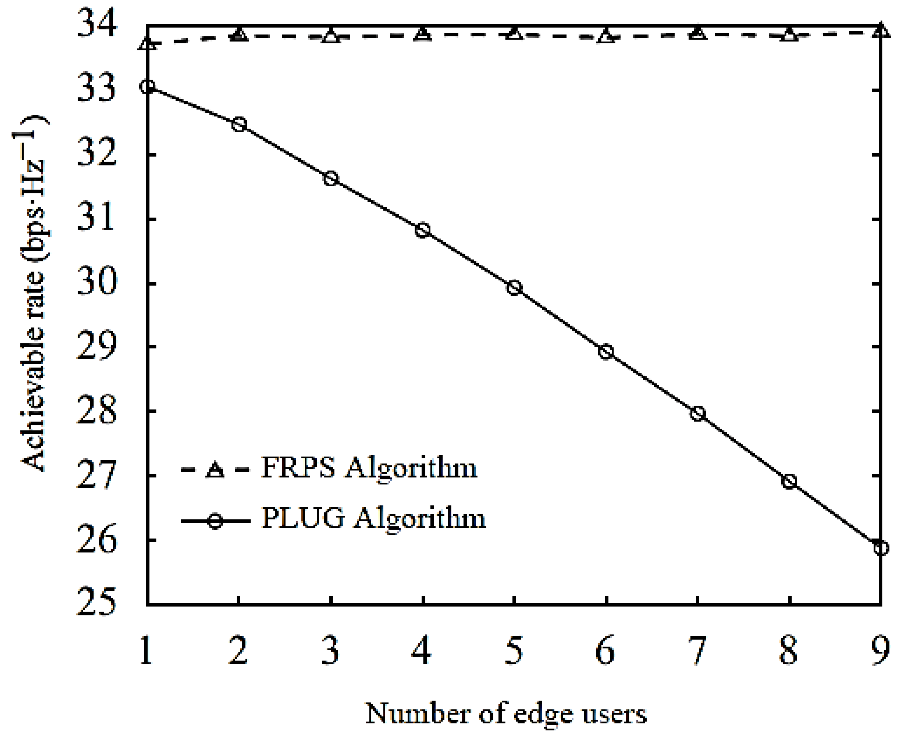
4.2. Analysis of PLUG Algorithm

Figure 8 and Figure 9 respectively show the performance of the channel estimation normalized MSE and uplink SINR of the central user and the edge user. The performance of the uplink SINR varies with the number of antennas.
It can be seen from Figure 8 and Figure 9 that the channel estimation normalized MSE of the edge user and the central user under both algorithms has a decreasing trend with the increase in the number of antennas. However, the MSE and SINR curves of the central users in both algorithms overlap, indicating that the center user multiplexes the pilots and causes the same pilot contamination. The edge user allocates orthogonal pilots under the PLUG algorithm, so there is no pilot contamination. When the number of antennas is 256, the NMSE performance of the edge users is increased by 10.88 dB, and the SINR performance is improved by 3.23 dB. Figure 10 is a graph showing the average achievable sum-rate performance of the center user and the edge user as the number of antennas increases when the number of edge users is one. Figure 11 shows the performance variation of the uplink achievable rate of the target cell of the central user and the edge user when the number of edge users is 1. It can be seen from Figure 10 that the average achievable rate of the central user in the PLUG algorithm is slightly lost. This is because the orthogonal pilot set is added under such algorithm, and the pilot overhead is increased, resulting in a decrease in spectral efficiency (SE), but the performance of the edge user is very good. With a large boost, the average achievable is increased by 0.42 bps/Hs when the number of antennas is 256. It can be seen from Figure 11 that the uplink achievable rate curves of the target cell are basically coincident under the two algorithms, which indicates that the PLUG algorithm does not bring loss to the overall performance of the target cell, but only increases the fairness of the central user and the edge use. It is also obvious from the results that the proposed PLUG algorithm reduces the probability of edge user communication interruption. Figure 12 compares the uplink target cell achievable rate in the case where the number of edge users of the FRPS and PLUG algorithms is different and for the number of antennas of 256. As can be seen from Figure 12, when the number of edge users increases, the achievable rate of the PLUG algorithm gradually decreases. This is because when the number of edge users is greater than one, the cost of pilot overhead exceeds the performance gains of the PLUG algorithm.

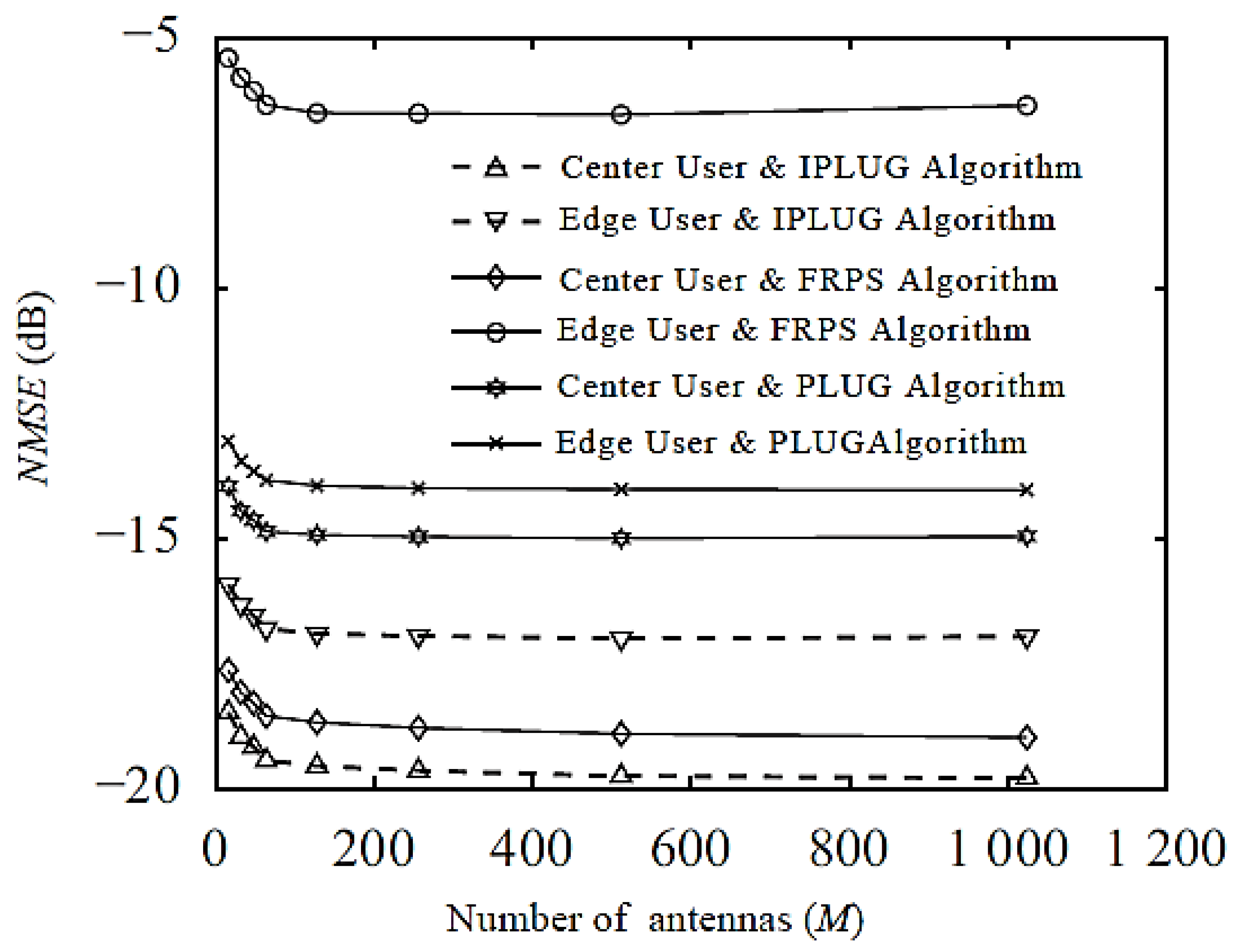
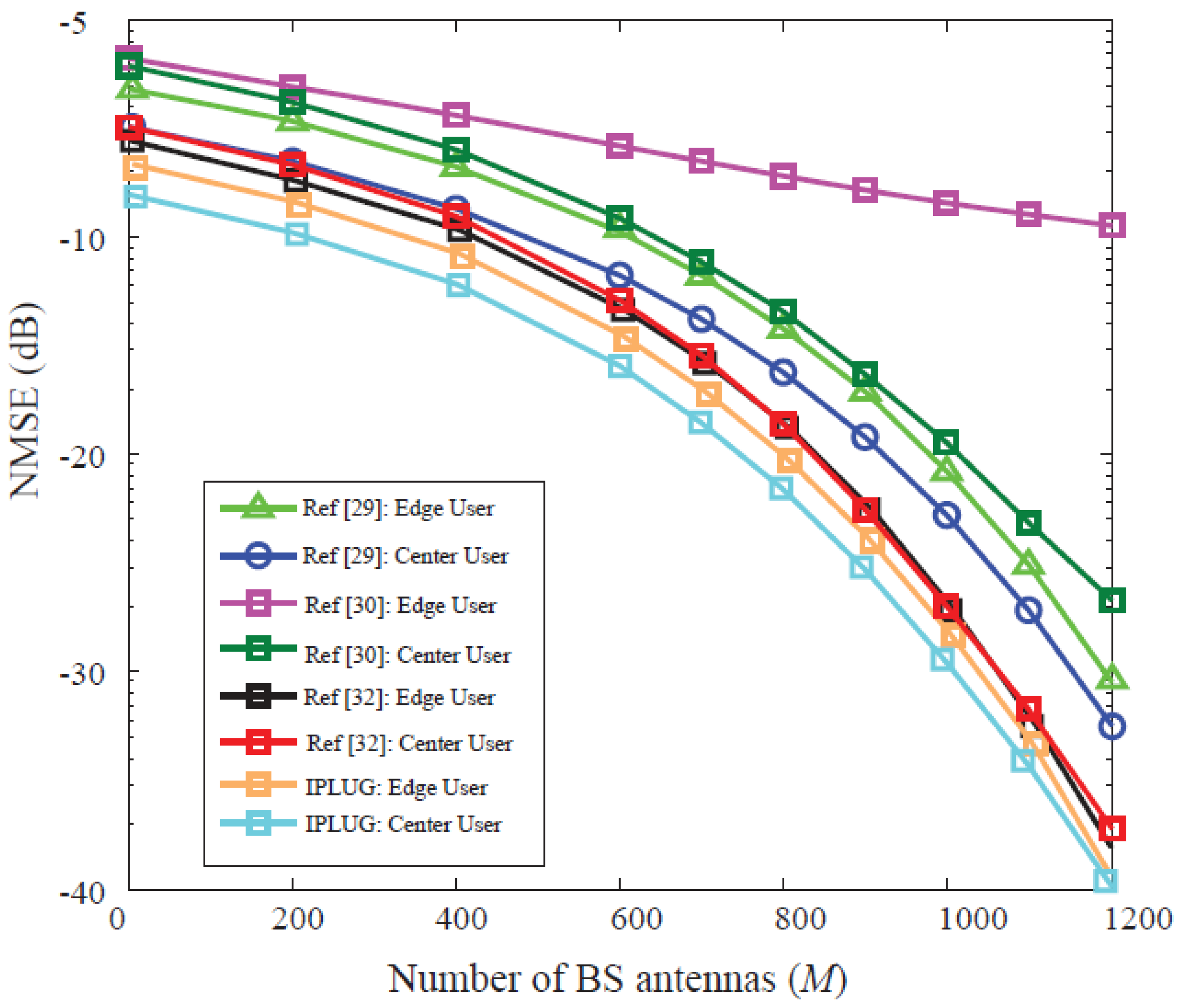
4.3. Analysis of IPLUG Algorithm

Figure 13 compares the NMSE of the central user and the edge user against the number of antennas for the FRPS, PLUG, and IPLUG algorithms, wherein the IPLUG algorithm corresponds to a decision parameter 0.9, and the PLUG algorithm corresponds to an edge user of 1. As can be seen from Figure 13, when the number of antennas is 256, the NMSE performance of the edge users under the IPLUG algorithm is 2.95 dB higher than that of PLUG algorithm, and the central user NMSE is improved by 4.68 dB. The improvement of channel estimation performance greatly improves the performance of uplink signal detection and downlink coding. This is due to the flexibility brought by the IPLUG algorithm.
Figure 14 compares the uplink target cell achievable rate for FRPS and IPLUG with different decision parameters when the number of antennas is 256. As can be seen from Figure 14, when the decision parameter increases to λ 0.68 , the achievable rate of the IPLUG algorithm gradually increases. Therefore, the achievable rate of the proposed IPLUG algorithm have significantly exceeded the FRPS algorithm, which is a clear advantage of the IPLUG algorithm, avoiding the waste of pilot overhead caused by some users with good channel conditions being misclassified as edge users, or some users with poor channel conditions are being misclassified as the central user which results in communication interruption.

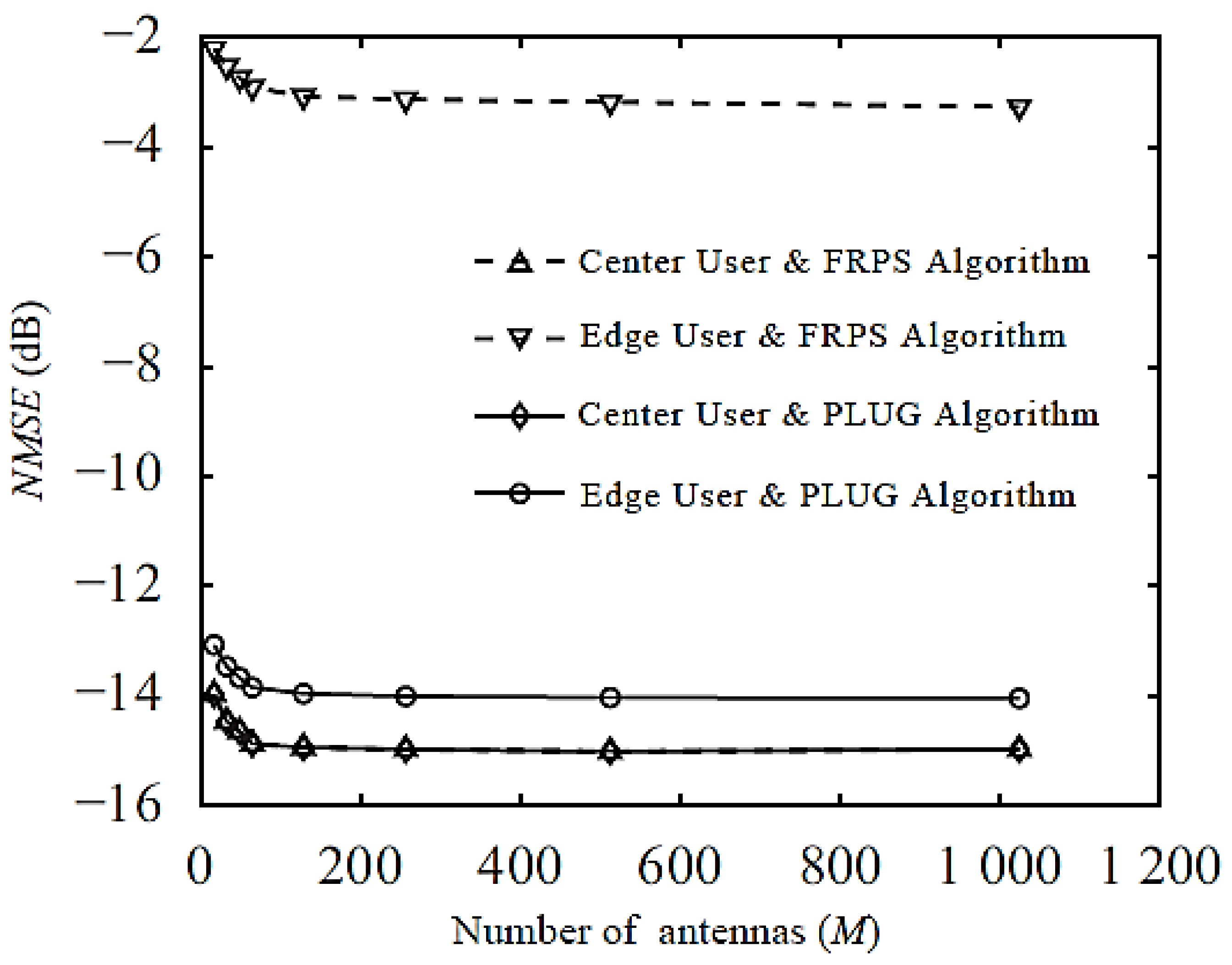
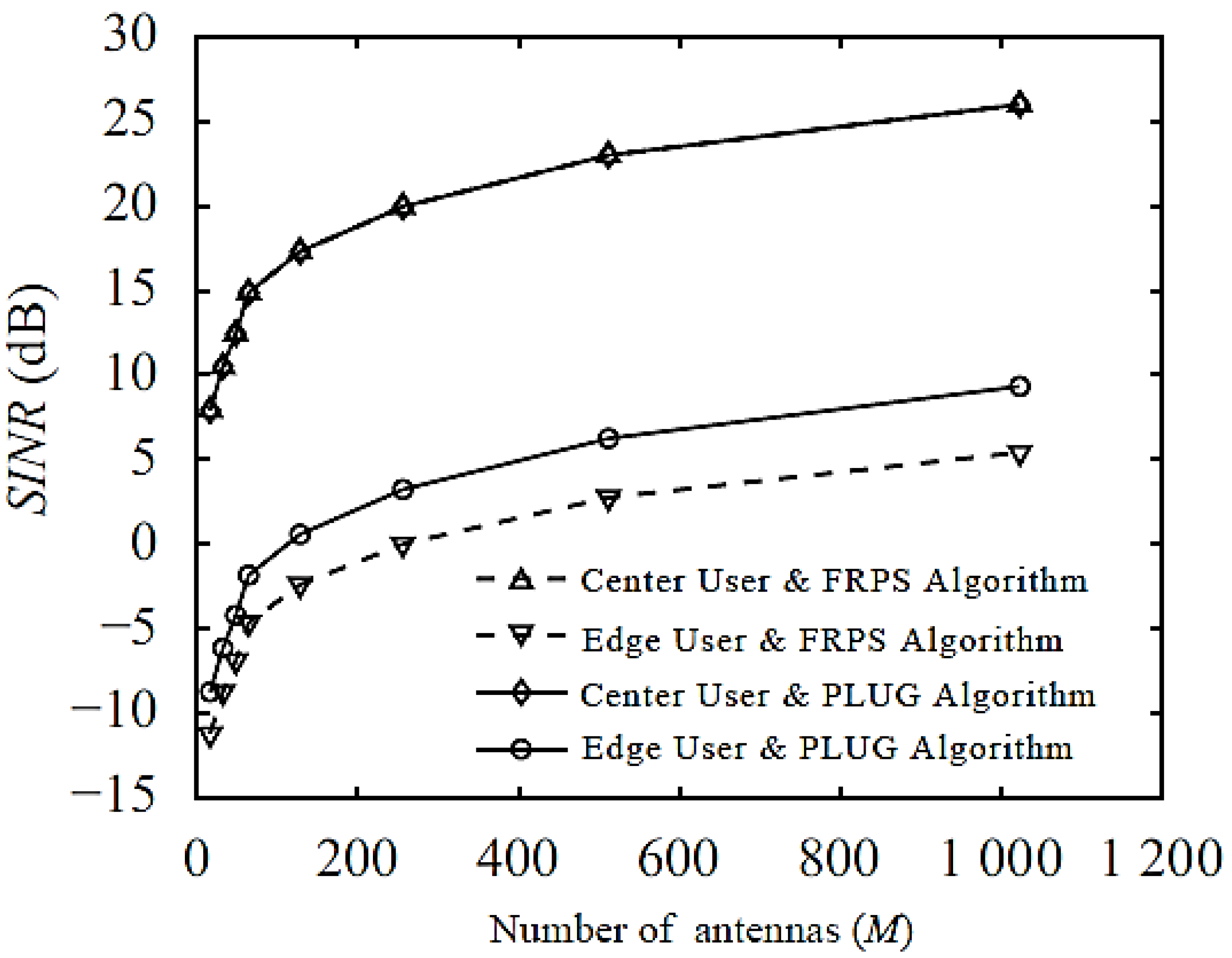
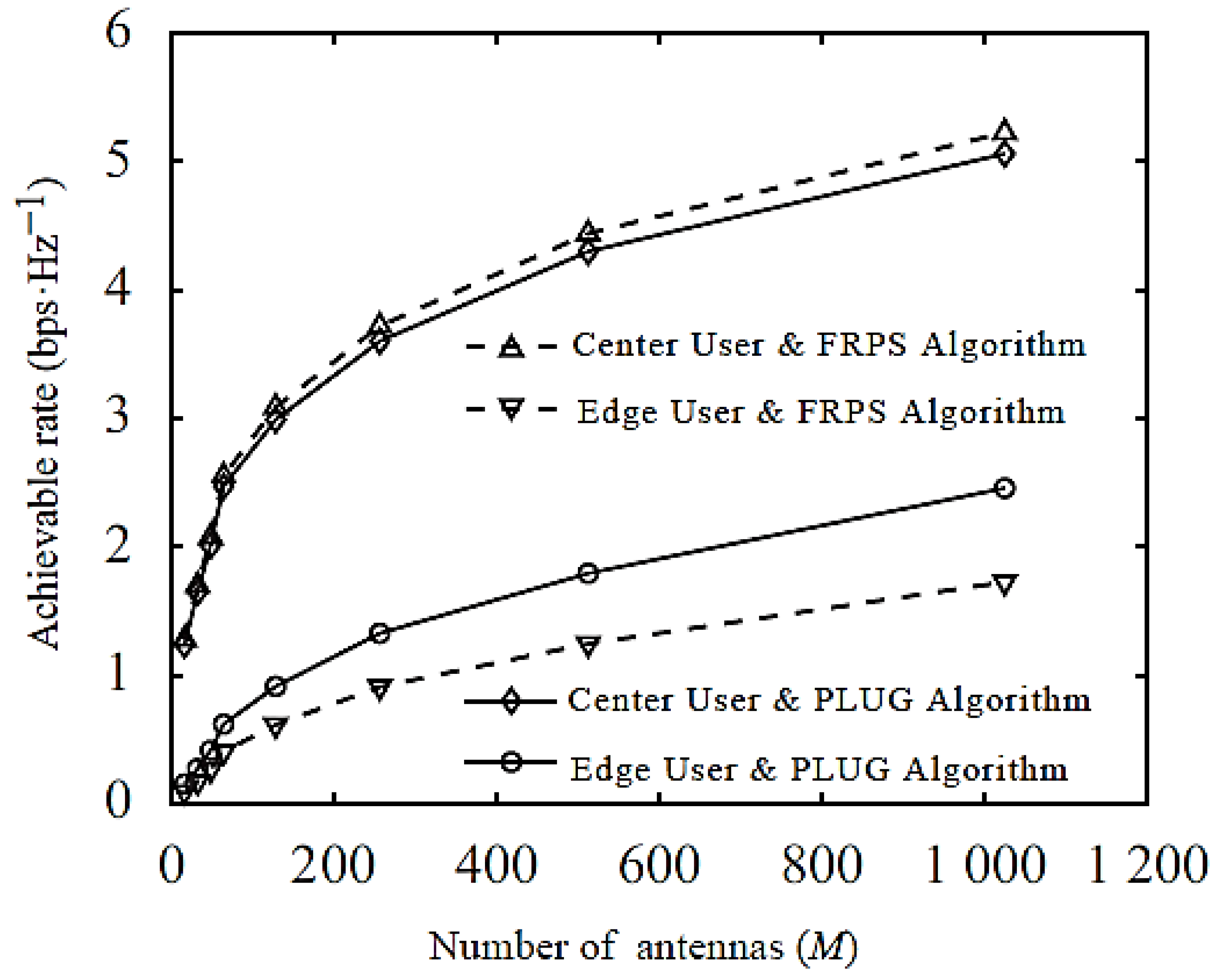
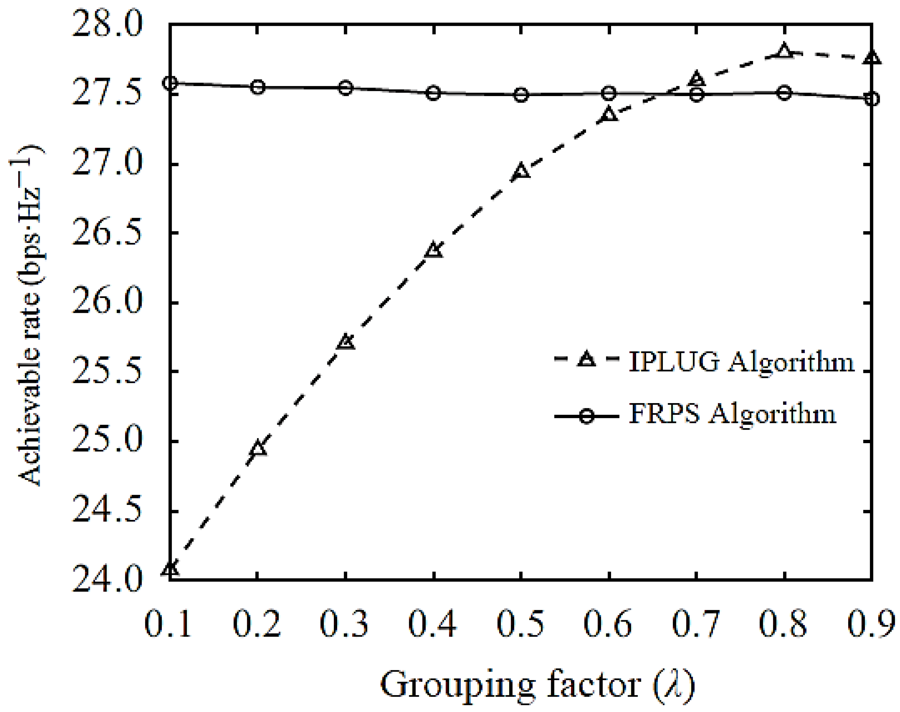
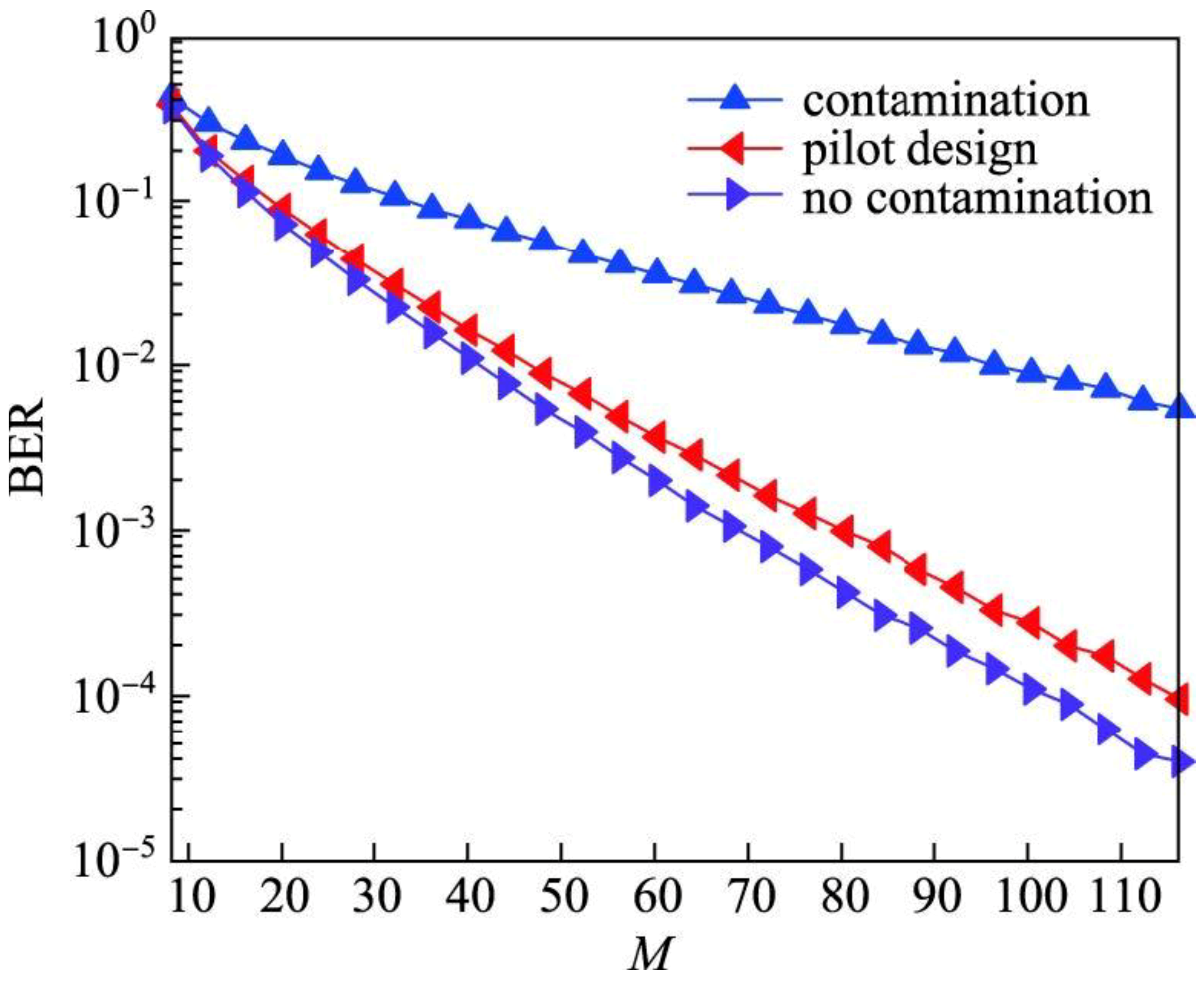
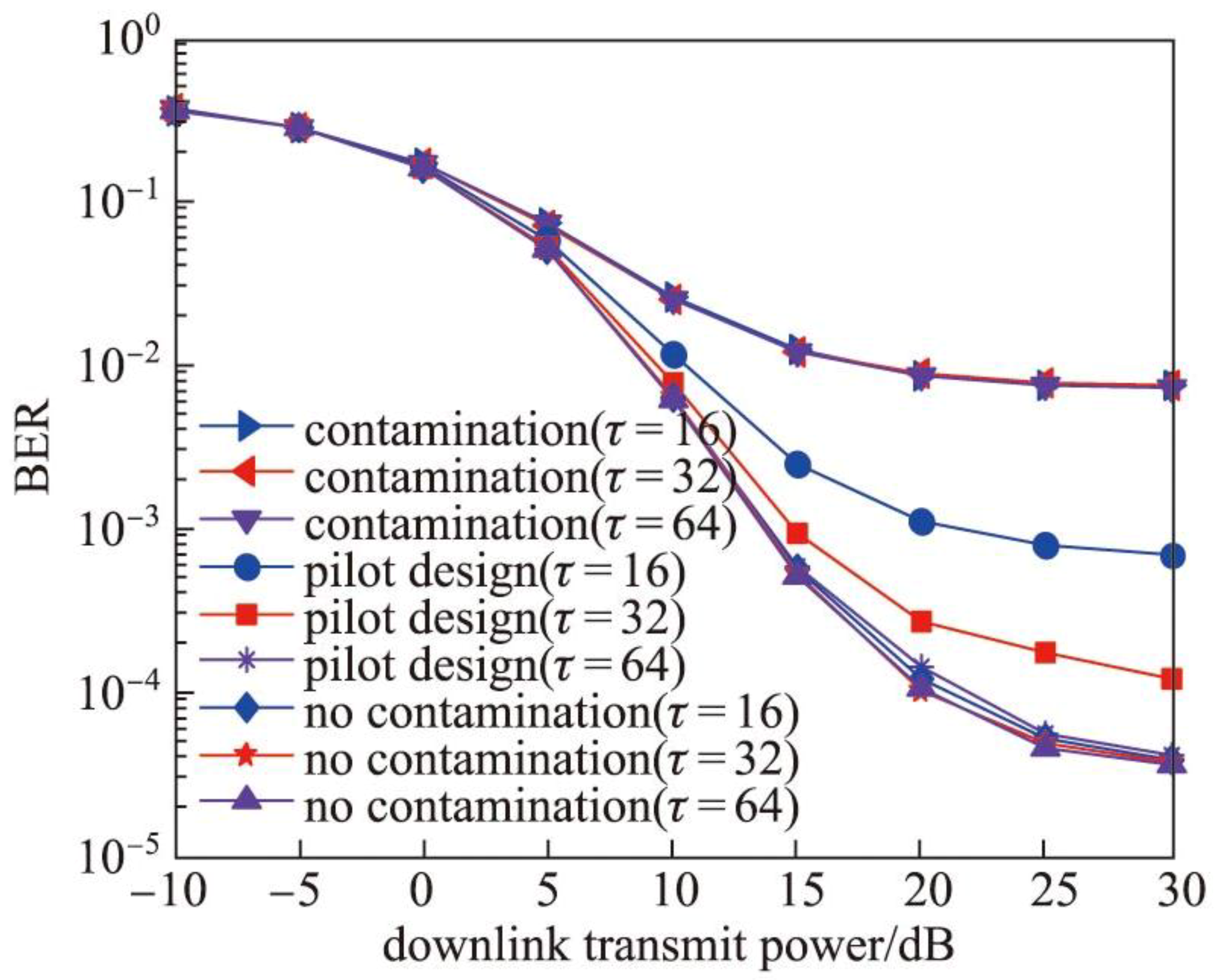
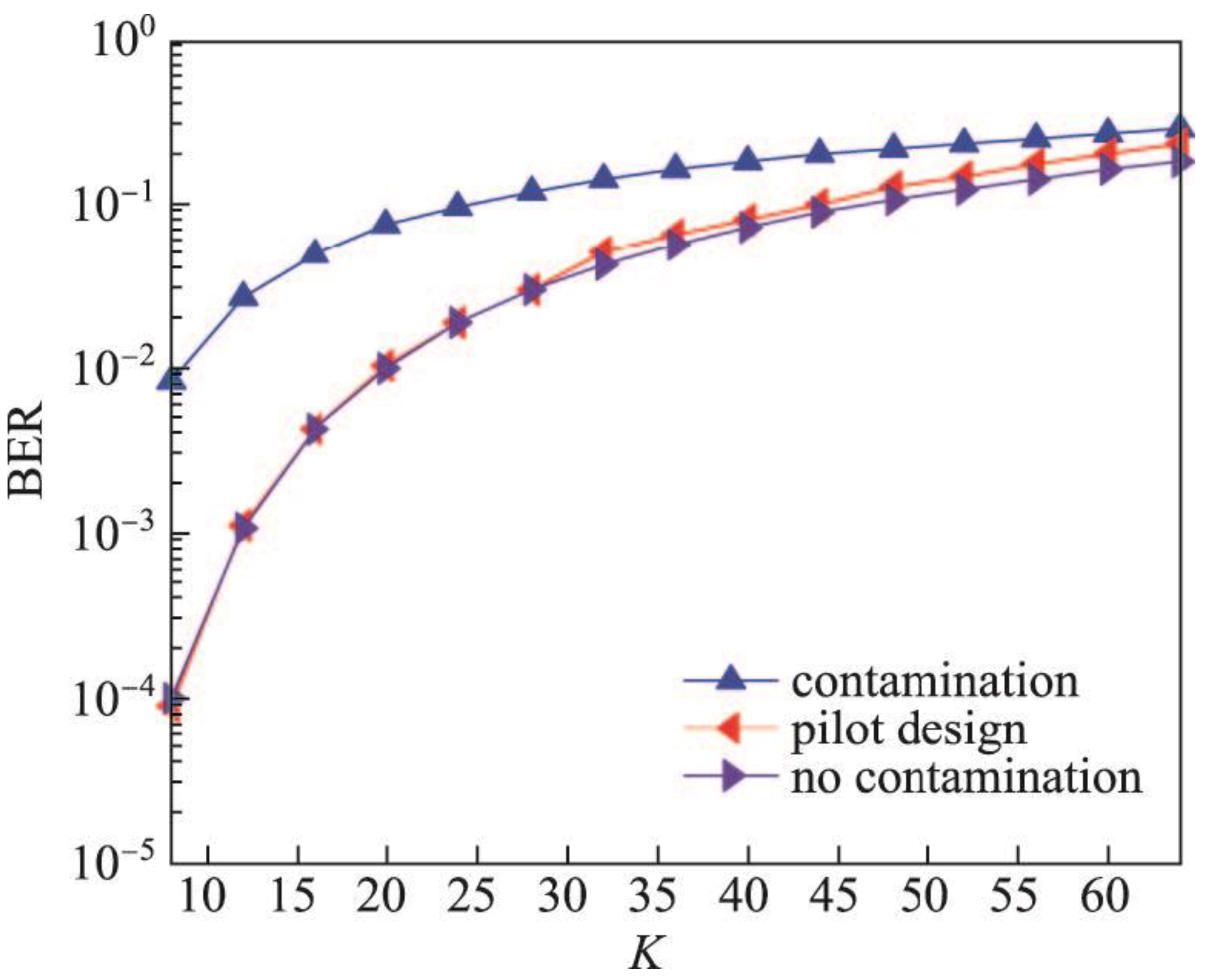
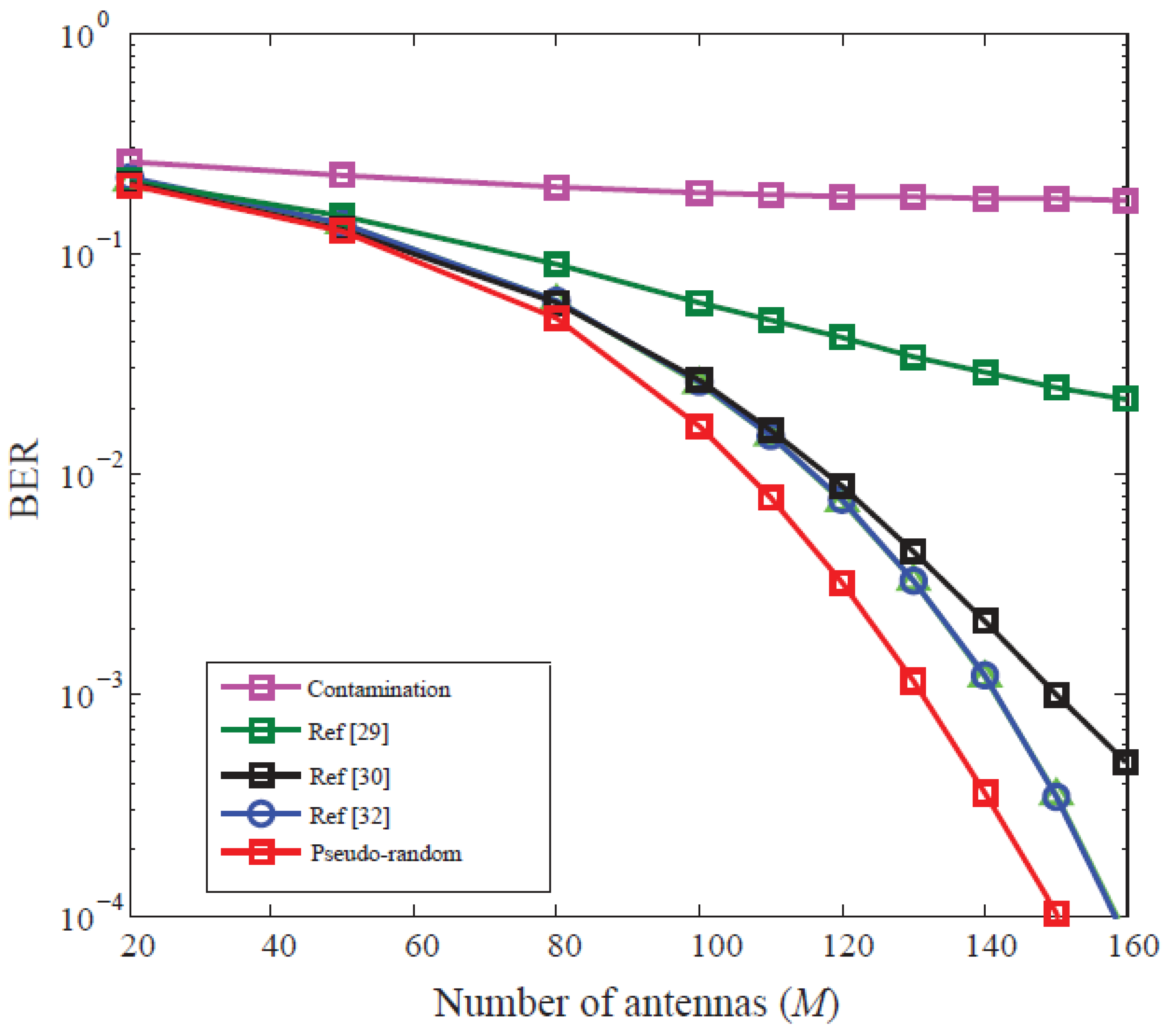
4.4. Analysis of Pseudo-Random Pilot Scheme

Figure 15 shows the probability density function (PDF) curves of the channel estimation MSE for the proposed pseudo-random scheme and compares it with no pilot contamination and with pilot contamination cases. The parameters set used for these results are: the number of users per cell is K = 4 , the number of BS antennas M = 100 and pilot length τ = 8 . It can be seen from Figure 15 that the MSE of the channel estimation that can be obtained by all cells multiplexing the same set of orthogonal pilots is around 1.63, and the MSE distribution of the channel estimation obtained by the pilot after the proposed pseudo-random pilot design is around 0.82. It can be seen that the proposed pseudo-random code scheme is opposite to the channel when all the cells are multiplexed with the same set of orthogonal pilots. The estimated MSE performance has increased nearly two times. Although all cells use orthogonal pilots, there is no pilot contamination, but there are certain uncorrelated noise and fast fading effects when the number of antennas is limited. The MSE of channel estimation is not 0. As the number of BS antennas increases, the uncorrelated noise and fast fading effects are gradually averaged, and the MSE of channel estimation gradually approaches 0.
Figure 16 depicts the trend of the system’s downlink transmission BER as the number of antennas increases. The number of users per cell is K = 8 , the number of BS antennas M = 100 and pilot length τ = 32 . It can be seen from Figure 16, as the number of BS antennas increases, the performance of the system is improved. In the case of full pilot contamination, the pilot performance is too serious, and the improvement of system performance is not obvious with the increase of the number of antennas. Therefore, it can be foreseen that when the number of antennas reaches a certain value, the system performance will not be improved.
When the proposed pilot design scheme or no contamination is used, the performance of the system is significantly improved with the increase of the number of antennas. Figure 17 depicts the trend of the downlink BER of the system as the average transmit power ρ f of the BS increases. The results are analyzed for different pilot lengths. The number of users per cell K = 8 , the number of antennas configured by the BS M = 100 . As can be seen from Figure 17 that when the number of BS antennas is large, the increase of the BS transmit power is effective for improving the system performance, but when it exceeds a certain value, the system performance will not be improved, and this value will be affected by the severity of pilot contamination. It can be seen from Figure 17 that in the case of complete pilot contamination, the system performance will not be improved after the BS transmission power reaches 25 dB. In the case of the proposed pilot design scheme (pseudo-random code) or no contamination, this value is greater than 25 dB. At the same time, it can be found that in the case of complete pilot contamination, the system performance will not be improved with the increase of the pilot length τ ; in the absence of pilot contamination, the increase of the pilot length can improve the system performance to a small extent, but there is no need to sacrifice pilot overhead to boost such tiny performance. After using the proposed pseudo-random pilot design scheme, the performance of the system will increase significantly with the increase of the pilot length. Furthermore, when the pilot length τ = 64 , the performance achieved by the proposed pilot design scheme is very close to the case of no pilot contamination. Figure 18 compares the BER of the proposed pseudo-random pilot design scheme with other cases versus the number of cell users K . The number of antennas configured by the BS is M = 100 , and pilot length τ = 128 . It can be seen from Figure 18 that in the case where the number of BS antennas is large, the increase in the number of cell users may deteriorate the performance of the system, but the performance of the system is still far better when the proposed pseudo-random pilot design or no pilot contamination scheme is used. At the same time, when the number of users is small and the pilot length τ = 128 , the same performance of the system can be almost achieved in the case of no contamination when the proposed pilot design scheme is adopted. This is because the increase in the length of the pseudo-random code can only make them infinitely close to the orthogonal but cannot completely remove the pilot contamination. In the case of a small number of users, the pilot contamination is small enough to affect the performance of the entire system. In the case of a large number of users, the impact on the overall system performance is considerable due to the superposition of pilot contamination. Overall, the proposed pilot design scheme is very obvious for the improvement of system performance.
Figure 19 compares the NMSE of the proposed IPLUG algorithm with the conventional state-of-the-art algorithms [29,30,32] wherein the IPLUG algorithm corresponds to a decision parameter 0.9. As can be seen from the figure that the proposed IPLUG algorithm shows better NMSE performance than the conventional algorithms for increasing number of base station antennas. Figure 20 compares.
Figure 20 illustrates the BER comparison of the proposed pseudo-random code scheme and the conventional schemes as the number of antennas increases. The number of users per cell is K = 8 , the number of BS antennas M = 160 and pilot length τ = 32 . It can be seen from Figure 20, as the number of BS antennas increases, the performance of the system is improved. The proposed pseudo-random code scheme shows better BER performance as compared with the conventional algorithms with increasing number of antennas.

5. Conclusions

This paper proposes a robust approach for effective pilot decontamination in massive MIMO systems. Two efficient pilot decontamination schemes are proposed. The first scheme is depending on Path Loss to perform User Grouping (PLUG) method while the second scheme is depending on the pseudo-random code. The PLUG scheme divides users into central and edge users. Edger users are allocated orthogonal pilots, and central users are assigned multiplex pilots, which improves edge user performance. The Improved PLUG scheme (IPLUG) is further proposed to overcome the deficiency of the PLUG scheme as it dynamically selects and correctly classifies the edge users and central users so that there is no wrong misclassification and therefore, the communication quality of service is improved. The analytical and simulation results show that the proposed IPLUG scheme can avoid the waste of pilot overhead caused by users with good channel conditions being misclassified as edge users, or the users with poor channel conditions being misclassified as central users, resulting in communication interruption, therefore, the proposed IPLUG scheme increases the fairness of communication for each user. The MSE of the expected channel estimation after the proposed pseudo-random code pilot design scheme is deduced and analyzed. It is found that this scheme can not only effectively improve the performance of channel estimation, but a more accurate channel estimation can be obtained by selecting an appropriate pseudo-random code and pilot length. Thereby improving the performance of the entire downlink system. The above conclusions are verified by numerical simulation. The numerical results also show that the proposed pilot design scheme depending on pseudo-random code can greatly improve the performance of the entire system limited by pilot contamination. The proposed PLUG and IPLUG schemes are focused only on the cells of the omnidirectional antenna, and other sector cells are not considered. At the same time, the pilot allocation is performed in the target cell, and the pilot allocation between the cells is independent of each other and has certain limitations. Therefore, the future research direction will be PLUG and IPLUG schemes depending on pilot decontamination in sectoral cells. The problem is to consider the mutual connection of each cell to reasonably allocate pilots throughout the system.

Author Contributions

Conceptualization, O.A.S., I.K. and B.M.L.; Data curation, O.A.S. and I.K.; Formal analysis, O.A.S., I.K. and A.T.; Funding acquisition, I.K. and B.M.L.; Investigation, O.A.S., I.K. and A.T.; Methodology, O.A.S., I.K., B.M.L. and A.T.; Project administration, O.A.S. and I.K.; Software, O.A.S., I.K. and A.T.; Writing—original draft, O.A.S., I.K. and B.M.L.; Writing—review & editing, O.A.S., I.K., B.M.L. and A.T.

Funding

This work was supported by the Basic Science Research Program through the National Research Foundation of Korea (NRF) funded by the Ministry of Education (grant number: NRF-2017R1D1A1B03028350).

Conflicts of Interest

The authors declare no conflict of interest.

References

  1. Khan, I. A Robust Signal Detection Scheme for 5G Massive Multiuser MIMO Systems. IEEE Trans. Veh. Technol. 2018, 67, 9597–9604. [Google Scholar] [CrossRef]
  2. Khan, I.; Singh, D. Efficient Compressive Sensing Based Sparse Channel Estimation for 5G Massive MIMO Systems. AEU Int. J. Electron. Commun. 2018, 89, 181–190. [Google Scholar] [CrossRef]
  3. Khan, I.; Zafar, M.H.; Jan, M.T.; Lloret, J.; Basheri, M.; Singh, D. Spectral and Energy Efficient Low-Overhead Uplink and Downlink Channel Estimations for 5G Massive MIMO Systems. Entropy 2018, 20, 92. [Google Scholar] [CrossRef]
  4. Khan, I.; Singh, M.; Singh, D. Compressive Sensing-Based Sparsity Adaptive Channel Estimation for 5G Massive MIMO Systems. Appl. Sci. 2018, 8, 754. [Google Scholar] [CrossRef]
  5. Molisch, A.F.; Win, M.Z.; Winters, J.H. Space-time-frequency (STF) coding for MIMO-OFDM systems. IEEE Commun. Lett. 2002, 6, 370–372. [Google Scholar] [CrossRef] [Green Version]
  6. Bolcskei, H.; Paulraj, A.J. Space-frequency coded broadband OFDM systems. In Proceedings of the IEEE Wireless Communications and Networking Conference (WCNC), Chicago, IL, USA, 23–28 September 2000; pp. 1–6. [Google Scholar]
  7. Darsena, D.; Gelli, G.; Paura, L.; Verde, F. Blind Channel Shortening for Space-Time-Frequency Block Coded MIMO-OFDM Systems. IEEE Trans. Wirel. Commun. 2012, 11, 1022–1033. [Google Scholar] [CrossRef]
  8. Redferm, A.J. Receiver window design for multicarrier communication systems. IEEE J. Sel. Areas Commun. 2002, 20, 1029–1036. [Google Scholar] [CrossRef]
  9. Darsena, D.; Gelli, G.; Paura, L.; Verde, F. NBI-resistant zero-forcing equalizers for OFDM systems. IEEE Commun. Lett. 2005, 9, 744–746. [Google Scholar] [CrossRef]
  10. Mergen, B.S.; Scaglione, A. Randomized Space-Time Coding for Distributed Cooperative Communication. IEEE Trans. Signal Process. 2007, 55, 5003–5017. [Google Scholar] [CrossRef]
  11. Knopp, R.; Humblet, P.A. Information capacity and power control in single-cell multiuser communications. In Proceedings of the IEEE International Conference on Communications (ICC), Seattle, WA, USA, 18–22 June 1995; pp. 331–335. [Google Scholar]
  12. Mastronarde, N.; Verder, F.; Darsena, D.; Scaglione, A.; van der Schaar, M. Transmitting Important Bits and Sailing High Radio Waves: A Decentralized Cross-Layer Approach to Cooperative Video Transmission. IEEE J. Sel. Areas Commun. 2012, 30, 1597–1604. [Google Scholar] [CrossRef] [Green Version]
  13. Rusek, F.; Persson, D.; Buon, K.L.; Larsson, E.G.; Marzetta, T.L.; Edfors, O.; Tufvesso, F. Scaling up MIMO: Opportunities and challenges with very large arrays. IEEE Signal Process. Mag. 2013, 30, 40–60. [Google Scholar] [CrossRef]
  14. Biswas, S.; Xue, J.; Khan, F.A.; Ratnarajah, T. Performance Analysis of Correlated Massive MIMO Systems with Spatially Distributed Users. IEEE Syst. J. 2016, 12, 1850–1861. [Google Scholar] [CrossRef]
  15. Khan, I. Channel modeling and analysis of OWC-massive MIMO Systems. Opt. Commun. 2018, 434, 209–217. [Google Scholar] [CrossRef]
  16. Marzetta, T.L. Noncooperative cellular wireless with unlimited numbers of base station antennas. IEEE Trans. Wirel. Commun. 2010, 9, 3590–3600. [Google Scholar] [CrossRef]
  17. Jose, J.; Ashikhmin, A.; Marzetta, T.L.; Vishwanath, S. Pilot contamination and precoding in multi-cell TDD systems. IEEE Trans. Wirel. Commun. 2011, 10, 2640–2651. [Google Scholar] [CrossRef]
  18. Ashikhmin, A.; Marzetta, T.L. Pilot contamination precoding in multi-cell large-scale antenna systems. In Proceedings of the IEEE International Symposium on Information Theory Proceedings (ISIT), Cambridge, MA, USA, 1–6 July 2012; Volume 1, pp. 1137–1141. [Google Scholar]
  19. Liangbin, L.; Ashikhmin, A.; Marzetta, T.L. Pilot contamination precoding for interference reduction in large-scale antenna systems. In Proceedings of the 51th Annual Allerton Conference on Communication, Control, and Computing, Monticello, IL, USA, 2–4 October 2013; Volume 2, pp. 226–232. [Google Scholar]
  20. Nguyen, T.M.; Le, L.B. Joint pilot assignment and resource allocation in multicell massive MIMO network: Throughput and energy efficiency maximization. In Proceedings of the IEEE Wireless Communications and Networking Conference (WCNC), New Orleans, LA, USA, 9–12 March 2015; pp. 393–398. [Google Scholar]
  21. Cheng, H.V.; Björnson, E.; Larsson, E.G. Optimal Pilot and Payload Power Control in Single-Cell Massive MIMO Systems. IEEE Trans. Signal Process. 2017, 65, 2363–2378. [Google Scholar] [CrossRef] [Green Version]
  22. Dao, H.T.; Kim, S. Pilot power allocation for maximizing the sum rate in massive MIMO systems. IET Commun. 2018, 12, 1367–1372. [Google Scholar] [CrossRef]
  23. Elijah, O.; Leow, C.Y.; Rahman, T.A.; Nunoo, S.; Iliya, S.Z. A Comprehensive Survey of Pilot Contamination in Massive MIMO—5G System. IEEE Commun. Surv. Tutor. 2015, 18, 905–923. [Google Scholar] [CrossRef]
  24. Hoydis, J.; Brink, S.T.; Debbah, M. Massive MIMO in the UL/DL of cellular networks: How many antennas do we need? IEEE J. Sel. Areas Commun. 2013, 31, 160–171. [Google Scholar] [CrossRef]
  25. Khan, I.; Zafar, M.H.; Ashraf, M.; Bayati, A.K.S. Computationally Efficient Channel Estimation for 5G Massive Multiple-Input Multiple-Output Systems. Electronics 2018, 7, 382. [Google Scholar] [CrossRef]
  26. Yin, H.; Gesbert, D.; Filippou, M.; Liu, Y. A coordinated approach to channel estimation in large-scale multiple-antenna systems. IEEE J. Sel. Areas Commun. 2012, 31, 264–273. [Google Scholar] [CrossRef]
  27. Neumann, D.; Joham, M.; Weiland, L.; Utschick, W. Low-complexity computation of LMMSE channel estimates in massive MIMO. In Proceedings of the 19th International ITG Workshop on Smart Antennas, Ilmenau, Germany, 3–5 March 2015; pp. 1–6. [Google Scholar]
  28. Ngo, H.; Larsson, E.G. EVD-based channel estimation in multicell multiuser MIMO systems with very large antenna arrays. In Proceedings of the IEEE International Conference on Acoustics, Speech and Signal Processing, Kyoto, Japan, 25–30 March 2012; pp. 3249–3252. [Google Scholar]
  29. Jin, S.; Wang, Z.; Zheng, L.; Wong, K.; Huang, Y.; Tang, X. On massive MIMO zero-forcing transceiver using time-shifted pilots. IEEE Trans. Veh. Technol. 2016, 65, 59–74. [Google Scholar] [CrossRef]
  30. Xiong, X.; Jiang, B.; Gao, X.; You, X. QoS-Guaranteed User Scheduling and Pilot Assignment for Large-Scale MIMO-OFDM Systems. IEEE Trans. Veh. Technol. 2015, 65, 6275–6289. [Google Scholar] [CrossRef]
  31. Dai, X. Optimal training design for linearly time-varying MIMO/OFDM channels modeled by a complex exponential basis expansion. IET Commun. 2007, 1, 945–953. [Google Scholar] [CrossRef]
  32. Saxena, V.; Fodor, G.; Karipidis, E. Mitigating pilot contamination by pilot reuse and power control schemes for massive MIMO systems. In Proceedings of the IEEE 81st Vehicular Technology Conference, Glasgow, UK, 11–14 May 2015; pp. 1–6. [Google Scholar]
  33. Zhu, X.; Wang, Z.C.; Dai, L.L.; Qian, C. Smart pilot assignment for massive MIMO. IEEE Commun. Lett. 2015, 19, 1–4. [Google Scholar] [CrossRef]
  34. Jin, S.; Li, M.; Huang, Y.; Du, Y.; Gao, X. Pilot scheduling schemes for multi-cell massive multiple-input-multiple-output transmission. IET Commun. 2015, 9, 689–700. [Google Scholar] [CrossRef]
  35. Litvinenko, L. OFDM signal PAPR reduction by pre-scrambling and clipping for frequency domain comb-type channel estimation case. In Proceedings of the 23rd International Conference Radioelectronika, Pardubice, Czech Republic, 16–17 April 2013; pp. 273–277. [Google Scholar]
  36. Yang, B.; Deng, C.J.; Wu, P.H.; Xi, J.; Shi, L. Image encryption algorithm depending on two-one-dimensional logistic chaotic inter-scrambling systems and m-sequence. In Proceedings of the IEEE International Conference on Software Engineering and Service Science (ICSESS), Beijing, China, 27–29 June 2014; pp. 521–524. [Google Scholar]
Figure 1. Massive MIMO multi-cell multi-user TDD system model.
Electronics 08 00055 g001
Figure 2. IPLUG policy decision parameters for user grouping.
Electronics 08 00055 g002
Figure 3. Proposed IPLUG algorithm flowchart.
Electronics 08 00055 g003
Figure 4. Pseudo-random code linear feedback shifter register.
Electronics 08 00055 g004
Figure 5. Pseudo-random code pilot design scheme.
Electronics 08 00055 g005
Figure 6. Proposed pseudo-random algorithm flowchart.
Electronics 08 00055 g006
Figure 7. Simulation scenario of massive MIMO system of seven cells.
Electronics 08 00055 g007
Figure 8. NMSE comparison of FRPS and PLUG Algorithms.
Electronics 08 00055 g008
Figure 9. NMSE comparison of FRPS and PLUG Algorithms.
Electronics 08 00055 g009
Figure 10. Comparison achievable rate of target cell of FRPS and PLUG algorithms.
Electronics 08 00055 g010
Figure 11. Achievable rate comparison of FRPS and PLUG algorithms for user fairness analysis.
Electronics 08 00055 g011
Figure 12. Comparison of achievable sum rate against a different number of edge users for FRPS and PLUG algorithms.
Electronics 08 00055 g012
Figure 13. NMSE comparison of IPLUG, FRPS, and PLUG algorithms.
Electronics 08 00055 g013
Figure 14. Comparison of achievable sum rate against a different number of user grouping factor λ for IPLUG and FRPS algorithms.
Electronics 08 00055 g014
Figure 15. PDF comparison of the proposed pseudo-random code scheme with other cases.
Electronics 08 00055 g015
Figure 16. Comparison of the BER of the proposed pseudo-random pilot design scheme with other schemes against the number of BS antennas.
Electronics 08 00055 g016
Figure 17. Comparison of the BER of the proposed pseudo-random code and another scheme versus the average BS power ρ f .
Electronics 08 00055 g017
Figure 18. BER comparison against the number of cell users for the proposed pseudo-random pilot design and other cases.
Electronics 08 00055 g018
Figure 19. NMSE comparison of IPLUG and conventional algorithms.
Electronics 08 00055 g019
Figure 20. Comparison of the BER of the proposed pseudo-random pilot design scheme with other schemes against the number of BS antennas.
Electronics 08 00055 g020
Table 1. Simulation Parameters.
S. NoParameter NameValue
1Number of BS antennas ( M )16~1024
2Number of users per cell ( K )10
3Antenna Spacing 1 2 λ c
4Pilot Length ( τ )128
5Path Loss Factor ( α )3
6Pilot overhead coefficient ( μ 0 )0.05
7Cell Radius ( R )1000 m
8Lognormal Shadow Fading 4 dB
9Number of simulations 5000
10Average transmit power at BS ( ρ f )20 dB
11Average transmit power at User ( ρ r )10 dB
12The upper limit of normalized cross-correlation ( γ )0.3
13Cross-gain ( β j l k )0.7

