1. Introduction
State-of-the-art methods for the intelligent maintenance of rotary machines rely on the timely and accurate analysis of condition monitoring signals, such as acoustic emissions (AE) [
1,
2,
3,
4] and vibration acceleration signals [
5,
6]. AE signals are sampled at very high frequencies, typically 1 MHz, to capture ultrasonic sounds released during the initiation and propagation of cracks in machine components. Maintenance decisions are made by detecting those faults through spectral analysis of the envelope signal. The envelope signal is obtained by demodulating the raw AE signal using the Hilbert transform, and its spectral analysis is carried out using the fast Fourier transform (FFT) algorithm. Spectral analysis of the AE envelope signals reveals useful information about underlying bearing faults that is of significant importance in the field of machinery fault diagnosis.
The FFT is one of the most popular transform algorithms in digital applications, used to calculate the discrete Fourier transform (DFT), quickly and accurately. Ever since its introduction, the computational advantages of the FFT have made it an essential algorithm with widespread applications in science and engineering, such as communication, signal processing, image processing, bio-robotics, and intelligent maintenance [
1,
2,
4,
7,
8,
9,
10]. The high-speed requirements of smart maintenance systems, such as fault diagnosis in rotary machines using the spectral analysis of AE signals, necessitate a high-performance FFT processor. Thus, design of an efficient FFT processor is of great significance in meeting the requirements of real-time applications in terms of speed, accuracy, low cost, and a smaller chip area. The FFT algorithm is mainly implemented on field-programmable gate arrays (FPGAs) [
10,
11,
12], which offer advantages such as higher performance, less design time, and lower costs than digital signal processor–based systems (DSPs) [
13,
14,
15]. Moreover, the increasing gate density of FPGAs in recent years has enabled designers to implement data-parallel signal processing algorithms by using massively parallel architectures that can meet high-speed processing requirements; this has resulted in implementations on FPGA that deliver outstanding performance in many applications.
With pervasive applications in signal processing, FFT is the most widely used block in DSP systems and often occupies most of the chip area in hardware implementations. Conventional FFT processors are usually implemented using the radix-2 decimation in frequency (R2DIF) algorithm, which reduces the complexity of computing DFT from O(N
2) to O(Nlog
2N) [
16,
17,
18]. To increase a system’s speed and throughput performance, and make it suitable for real-time signal processing, a pipelined architecture has commonly been applied to the hardware implementation of FFT processors [
19,
20,
21]. However, the increasing complexity and cost of existing designs inhibits their use for large-point FFT architecture. Likewise, the butterfly operation uses complex adders and multipliers for twiddle factors (TF) in the FFT processor. These complex multipliers are the primary speed bottlenecks in the architecture. In addition, TF values are usually pre-computed and stored in memory. Therefore, a large-point FFT implementation requires a large amount of memory, making the design even more complex and hence, costly [
18,
22]. Coordinate rotation for digital computers (CORDIC) is an effective method for overcoming the memory problem of FFT computation [
23]; it can significantly reduce the resources required to implement TF multiplication. In [
24], a memoryless architecture for FFT computation was presented using CORDIC to minimize the memory requirements, but its hardware structure is quite complex. Another CORDIC-based FFT processor was proposed in [
25], with a reduced memory footprint and relatively low power consumption. However, it was primarily a memory-based design and offered comparatively slower processing speed due to the high latency in its architecture.
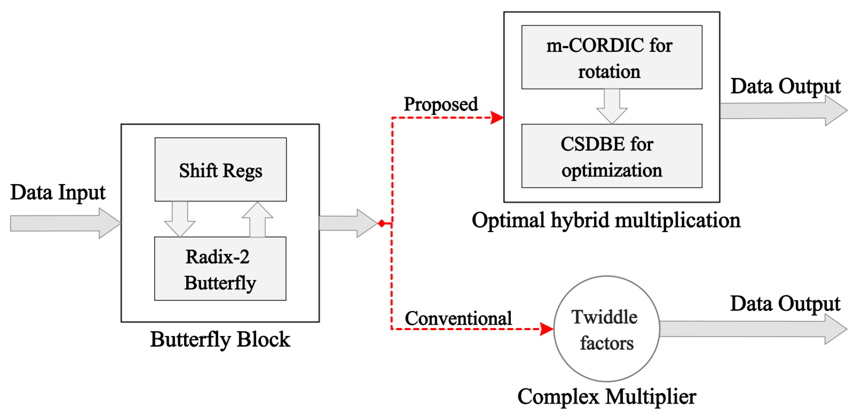
In this paper, an efficient FFT processor is implemented using a feedback pipelined technique (FB), which yields a relatively simple architecture that uses fewer resources and occupies a comparatively smaller area on the chip than existing systems, while delivering high-speed performance. The most important feature of the FB architecture is a feedback loop that allows the outputs of the butterfly units to be fed back to the same memory that is used to store the inputs. This storage sharing at each stage of the FFT processor reduces the hardware complexity. This proposed R2DIF, FB pipelined-based FFT processor (R2FB) employs an optimal hybrid rotation scheme based on a modified CORDIC algorithm (m-CORDIC) and a binary encoding technique based on a canonical signed digit (CSD) to entirely replace the complex multipliers, reducing the memory required to store the TFs and improving system speed and resource utilization. The proposed m-CORDIC algorithm uses a controllable iterative mechanism to enhance the system response time, which is an efficient way to realize the butterfly operation without requiring any dedicated complex multipliers. As an alternative approach for storing the complex TF values, the proposed m-CORDIC and CSD–based hybrid rotation scheme stores only the real TF angles for the butterfly operations, making the hardware design very flexible and efficient by requiring only adders and shifters in FFT computation, thereby saving resources and chip area. Furthermore, the proposed R2FB pipelined FFT processor is implemented using only the distributed logic resources in the architecture, thereby saving significant resources by eliminating the dedicated functional blocks that are widely used by existing implementations. The proposed R2FB pipelined FFT processor is synthesized in its entirety on the Xilinx Virtex-7 FPGA kit for testing and evaluation.
The main contributions of this paper are listed as follows:
The design of an efficient FFT processor, in terms of speed, accuracy, and resource utilization that is suitable for real-time signal processing and requires less area on a chip, remains a challenging problem. The proposed R2FB design exploits the FB technique and reduces the memory required at each stage of the pipeline by sharing registers between the input and output at each stage, thereby improving both the utilization of hardware resources and execution time. The proposed pipelined architecture offers a more flexible and less complex hardware implementation of FFT than current designs.
The m-CORDIC and CSD–based optimal hybrid rotation scheme is proposed to replace the complex TF multipliers in FFT, which reduces the memory requirements, optimizes the area on the chip, and improves the processing speed. The proposed m-CORDIC uses a conditional iterative mechanism via a predefined threshold to determine the number of effective iterations, which improves the convergence of the algorithm. The proposed optimal hybrid rotation scheme uses the shift-add method and does not require the dedicated functional blocks in the architecture, which are available in limited numbers on a target FPGA chip, while still guaranteeing high performance in terms of speed and precision. With these novel improvements, the proposed design uses only the distributed logic resources, yielding a highly efficient FFT processor, as demonstrated by the experimental results.
Furthermore, the proposed pipelined design uses shift registers replacing the slower memory blocks to store both the input data and the outputs. This memory-sharing mechanism improves the speed of the FFT processor and saves more registers and memory in the architecture. The data paths for the proposed architecture are designed as signed fixed-points and use the number of variable fractional bits at each computational stage in a pipelined architecture to enhance the precision of the final results.
The remainder of this paper is organized into the following sections. An overview of the R2DIF algorithm for FFT computation is given in
Section 2.
Section 3 briefly describes the m-CORDIC and CSD–based optimal hybrid rotation scheme and its hardware implementation on FPGA. The hardware implementation of the proposed R2FB pipelined processor for the FFT computation is presented in
Section 4, and
Section 5 analyzes the experimental results and compares them with those of existing designs. Finally, this work is concluded in
Section 6.
2. The Radix-2 Decimation in Frequency (R2DIF) Algorithm for Fast Fourier Transform
The N-point DFT transforms an input signal
into its equivalent representation in frequency domain
using the following relation:
where
is the twiddle factor (TF) for rotation, which is given as follows:
The FFT is mostly used to compute the DFT quickly by reducing the number of operations from
to
. An efficient radix-2 decimation in frequency (R2DIF) algorithm for FFT is applied to decompose the N-point input
into even samples
, and odd samples
, as given in Equations (3) and (4), respectively.
Here,
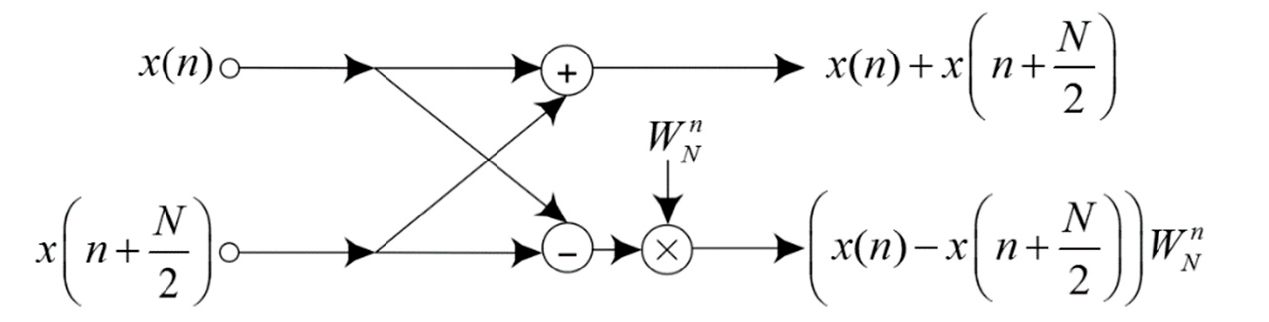
. A radix-2 butterfly unit for FFT computation is shown in
Figure 1; it involves an adder and a subtractor followed by a TF multiplier. Because the R2DIF yields the smallest butterfly unit in the architecture, it makes the design space more flexible relative to other algorithms. Calculating N-point FFT requires
stages, and each stage includes
butterfly units, i.e., a sum of
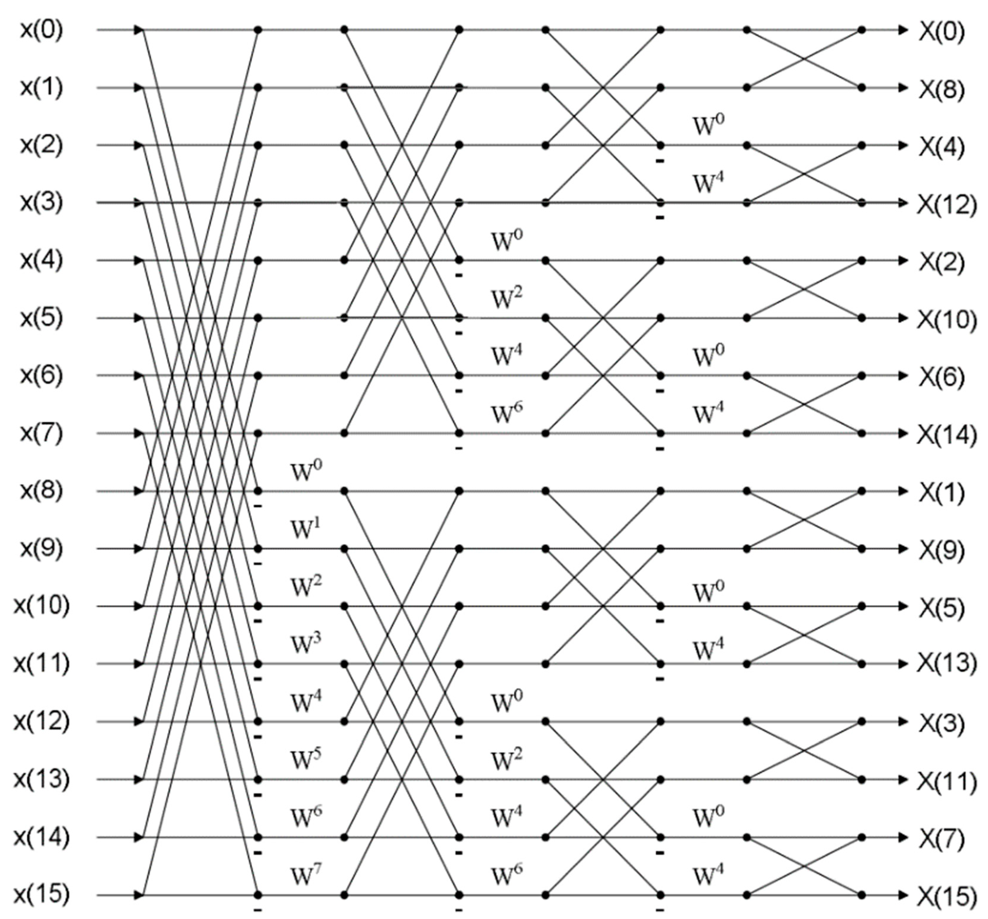
butterfly units for N-point FFT. The signal flow graph of a 16-point FFT using R2DIF algorithm, which consists of 32 butterfly operation units in the entire structure, is shown in
Figure 2.
3. The Proposed Modified Coordinate Rotation Digital Computer (m-CORDIC) and Canonical Signed Digit (CSD)-Based Rotation Scheme
The CORDIC is an effective alternative approach that can be utilized to compute complex arithmetic functions, including logarithmic, hyperbolic, and trigonometric, only using basic operations such as shifting and adding [
23]. It can be applied to multiply the complex twiddle coefficients for butterfly operation units in an FFT processor, without requiring any dedicated multiplier blocks, thereby reducing the area required on the chip and hence its cost and power consumption. The CORDIC also saves memory resources that would otherwise be required to store the complex TF values. These savings in time and memory resources make the proposed design faster and more resource efficient than existing systems. Furthermore, the CSD technique is used to optimize resources of the constant coefficient multipliers on hardware [
26]. The proposed m-CORDIC and CSD–based optimal hybrid rotation methodology implemented in this study is explained below.
3.1. CORDIC-Based Complex Multipliers
In this paper, the multiplication of the input data
by the complex TF values
, i.e.,
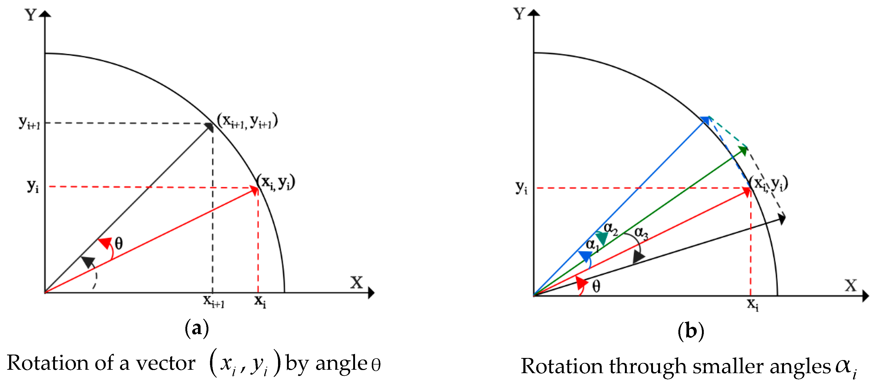
is equivalent to the rotation of an input vector by the angle
, such that
, as shown in
Figure 3a. Assuming rotation of a vector at the coordinates
is performed by an angle
in the x-y plane to the new coordinates
, its equation is given in matrix form as follows:
Equation (5) can be modified to obtain the following form:
The presence of trigonometric functions makes the implementation of Equation (5) and Equation (6) complex. Therefore, a practical approach is proposed to break the arbitrary angle
into a series of smaller angles
such that
, with
representing the direction of rotation for each iterative step
, as presented in
Figure 3b. By using the arithmetic property of the tangent function, i.e.,
, the complexity of the tangent function is reduced into a series of simple shift operations corresponding to each step
. Thus, the desired angular rotation is performed using an iterative series of rotation steps via the smaller angles
. The equation for the rotation can be rewritten as follows:
where
is the scale coefficient for each iteration step:
Equation (8) is derived from the trigonometric identities. After
iterative steps, the scaling coefficient
is obtained as follows:
To compute the R2DIF algorithm,
when the number of iterations is sufficiently large. The rotating direction
is chosen appropriately depending on the accumulated angle
. The value of
shows the angle difference between the expected rotation and the iterative rotation:
is determined as follows:
In a more general form, the rotation equations of the CORDIC for computing complex numbers are given in Equation (12), after dropping the scale coefficient
for hardware simplicity. Because this scale factor contains only magnitude information and is independent of the rotation angle, the final scaling coefficient
reaches a certain constant value after
iterative steps. The magnitude of the final output is thus scaled by
at the end, instead of scaling it for each rotation step.
In addition, with .
Instead of performing the rotation directly through an angle
, CORDIC performs it using a number of rotations via the smaller angles
Assuming that we would like to perform
iterations with number of angle constants
, as presented in
Table 1, the CORDIC algorithm exploits all these angle values and their direction
to compute the desired result, as described in Equation (7). It means that the rotating angle
is computed in 20 iterations: i.e.,
. The rotations around the desired angle corresponding to clockwise or anticlockwise via the sequential values of the
angle are efficiently computed using only shift and add operations.
3.2. Implementation of the Pipelined-Based Modified CORDIC Algorithm
There is no general consensus on the number of iterations that the CORDIC algorithm requires for convergence. Thus, the conventional CORDIC usually has a slow response time because of the indeterminate nature of the number of iterations that it requires to converge. This paper proposes a modified CORDIC algorithm (m-CORDIC) in which the iterations are investigated automatically to improve its convergence and save computational time. The proposed m-CORDIC algorithm overcomes the disadvantage of the conventional algorithm using an integrated comparator block to compare the angle accumulator
to a hard threshold value
after each iteration
such that
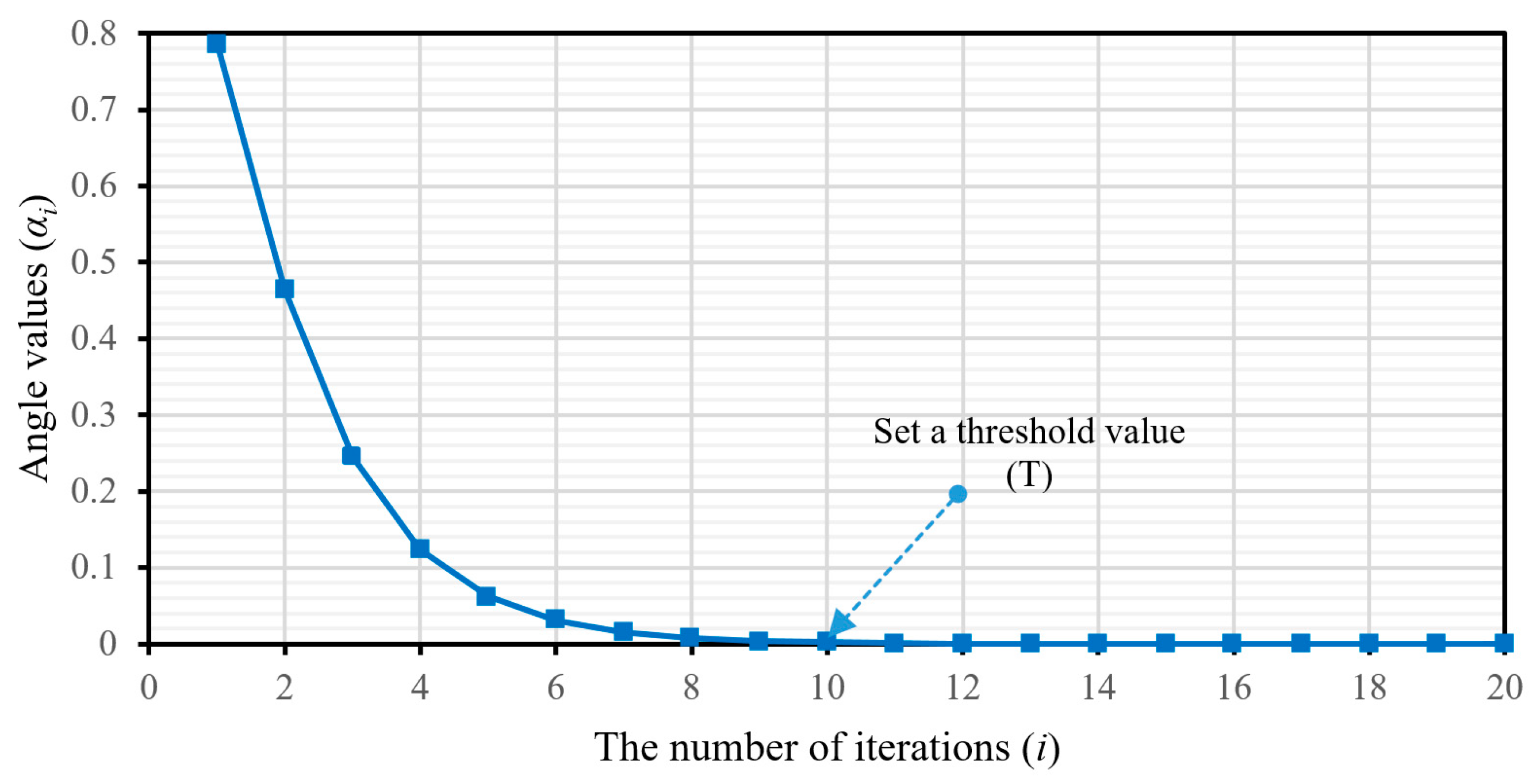
converges to zero. In this paper, the threshold value is set appropriately at a very small variance of the rotation angle constants around the desired angle, which ensures high accuracy of the computation. The iteration stops when
approaches a value smaller than the predefined threshold. For the rotation angle values in
Table 1, the threshold value is chosen to achieve the desired convergence, as illustrated in
Figure 4. The proposed algorithm is given below. When the input angle is
, as mentioned above, the conventional CORDIC requires almost 20 iterations to achieve the desired angle. The proposed method takes only nine iterations to converge to a very small residual value of 7.16 × 10
−4.
| Algorithm 1 The m-CORDIC using the controllable iterative mechanism |
| Start with the input values: xin, yin, zin |
| With i from 0 to n − 1, calculation: αi = arctan(2−i) |
| Definition of the initial z0 angle accumulator |
| Select the threshold value: T = α10 |
| The initial iteration: i = 0 and |
| Consideration of the conditions: |
| while zi > T and select = 1 do |
| update the data values |
| if zi ≥ αi |
| xi+1 = xi −yi·2−i |
| yi+1 = yi + xi·2−i |
| zi+1 = zi − αi |
| else |
| xi+1 = xi +yi·2−i |
| yi+1 = yi - xi·2−i |
| zi+1 = zi + αi |
| end if condition |
| i = i + 1 |
| end while condition |
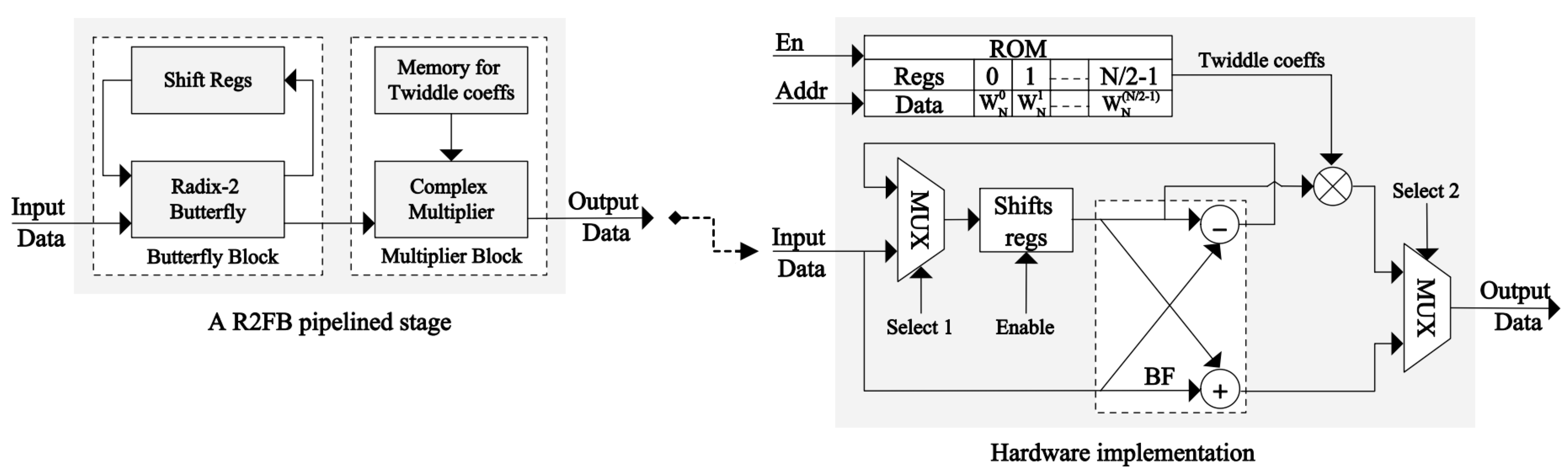
Hardware implementation of the m-CORDIC is performed using the pipelined technique, as presented in
Figure 5, where each pipelined stage mainly includes shifters, adders, and comparators for conditional multiplication; whereas, the registers for storing data are located between stages. The iterative operations in Equation (12) are performed in parallel in an unrolled manner such that each processing element in the architecture always executes in the same iteration. This iterative structure is easily pipelined by inserting registers between different stages to store the intermediate data for further computation. Therefore, the m-CORDIC computes directly using the input data, which allows for a substantial reduction in buffer memory blocks and the complete removal of the complex multipliers in FFT rotation. The controller correctly determines the amount of shift and the kind of calculation to execute at each clock cycle. The rotated directions of the original vector for the next iteration are determined from the signed bit of the previous accumulated angle
. Through these rotated directions, the types of arithmetic operations
are defined at each pipelined stage in the architecture. The initial angle
equals the desired angle value; after
iterations are completed using the aforementioned approach, the achieved angle
is equal to or smaller than the specified threshold, which is also the convergence condition of the algorithm. The computational precision of the algorithm is accumulated via each stage in the architecture, such that a pipelined stage corresponds to an iterative step of the algorithm.
For a sufficient number of iterations , the accumulated scaling coefficient is . The final results need to be multiplied by this scaling coefficient. Because is a constant value, an improvement of its multiplication can be performed by the optimal hybrid rotation scheme for the m-CORDIC architecture using the CSD technique. This scheme further reduces chip area requirements while saving processing time.
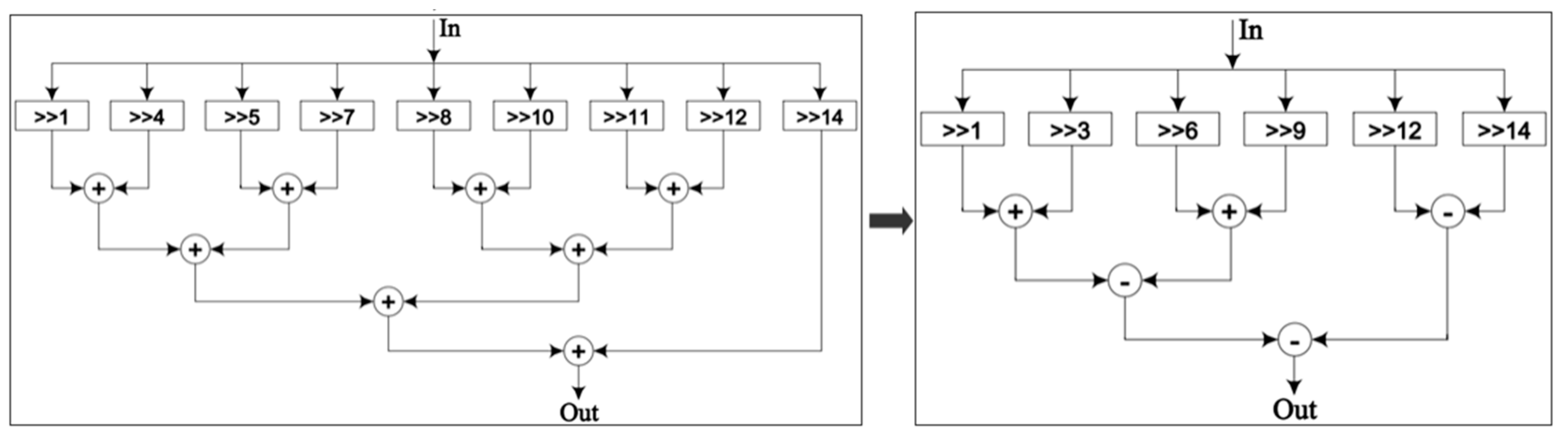
3.3. CSD Representation in Optimizing the Constant Multipliers
In general, multipliers often take a lot of area on the chip. However, the constant coefficient multipliers can be realized using adders and shifters only. The shifters and adders depend on the number of non-zero bits in the binary constant. In this study, CSD is used as an efficient solution for the binary representation of a constant because it has the least number of non-zero bits that are non-consecutive; therefore, it requires the fewest shifters and adders to determine the product. The CSD is presented in Algorithm 2.
| Algorithm 2 The CSD for a constant representation |
| 1: count of the number of consecutive “1” bits in a binary series |
| 2: if , replacing them by a new sequence 10…01, where 1: +1 and 1: – 1 |
| e.g., ; ; |
| 3: continue checking and replacing the value pairs: ; ; |
| e.g., |
The CSD can significantly reduce the number of shifters and adders required for the multiplication of a constant, thereby reducing its area and power consumption and enhancing its performance. This study uses CSD to optimize the multiplication of the final results by the constant scaling factor
after determining the number of iterations
of the m-CORDIC. The 16-bit conventional binary and CSD-based representations for
are given in
Table 2, along with a comparison of resource utilization for the multiplier in each case, as shown in
Figure 6. The results show that implementation of constant multipliers using the proposed approach needs about 37.5% fewer hardware resources.
5. Experimental Results
The proposed R2FB pipelined FFT processor and the other aforementioned designs for comparison were implemented on a Virtex 7 XC7VX485T FPGA using the Verilog hardware description language. The functional verification, timing simulation, and synthesis were performed using the specialized Xilinx Vivado Design Suite tool. The data paths are designed in a signed fixed-point format with 16-bit word length and 10-bit precision for the fractional part. The output is formatted dynamically such that the number of fractional bits is variable at each computational stage to improve the system precision.
The conventional R2FB design (A) was implemented using mainly the memory blocks for storing the complex TF coefficients that were pre-computed for FFT. The register slices and LUTs were utilized to compute and store the generated intermediate data during the operation process, whereas the complex multiplications were realized using DSP blocks embedded in the FPGAs. The modified R2FB design (B) was implemented using the distributed logic of CLBs and LUTs for computation instead of a large number of embedded dedicated blocks on the FPGAs. In this case, the slice registers and LUTs effectively replaced the memory blocks, storing both the complex TF coefficients and the intermediate data. In hardware implementations, multiplications by the complex TF values in FFT are commonly processed by the DSP blocks, which usually occupy a significant area space on FPGAs. Thus, a hardware implementation of the complex multipliers must be carefully considered to optimize chip resources and enhance processing speed. For this system (B), using the radix-2 algorithm and the number of FFT points defined for a system to determine the TF values as constants using Equation (2), and those values are then stored as a lookup table. Hence, the FFT rotation becomes a series of complex constant multiplications that can be calculated using the shift-add method instead of embedded DSP blocks. This way, this approach saves 100% of the dedicated functional blocks on FPGAs, but it consumes many of the distributed logic resources. In contrast to those conventional approaches, the proposed R2FB pipelined FFT processor (C) also uses only the slices of distributed logic on a chip without requiring any complex multiplication blocks or memory blocks for storage in architecture. The m-CORDIC and CSD–based optimal hybrid rotation method for this design improves resource utilization, reduces hardware complexity, and lowers costs, resulting in higher efficiency both in terms of resources and speed compared to the other designs. An evaluation of the hardware complexity and performance of the three approaches for a 1024-point FFT processor is provided in
Table 3.
The proposed R2FB pipelined FFT processor uses the input data directly for computation, enabling it to process faster and at less power than the conventional designs leaning more on memory based architecture, which use the slower and more power intensive load instructions to fetch the TFs. As shown in
Table 3, the proposed architecture (C) for computing 1024-point FFT can save the distributed logic resources about 13.53% in slice registers and 27.37% in slice LUTs and improve the processing speed by about 49% compared to the modified approach (B).
In this paper, all three designs used the distributed logic resources of slice registers and LUTs to implement their logic functions, which is a general measure of the area on FPGAs. However, the conventional memory-based designs also use dedicated block random-access memory (BRAM) and 48-bit DSP element (DSP48E) functional blocks. The area of design is usually measured through the number of slice registers, LUTs, BRAMs, DSP48Es in the architecture. It is essential to estimate the area of all designs precisely using an effective common metric. In this paper, we measured the area required by all designs using the number of slices, the primary element in all FPGAs, as the main metric. In the Virtex-7 family, each DSP48E block consists of an adder, a 25 × 18 multiplier, and an accumulator, whereas each BRAM block is fundamentally 36 Kb in size and can be used for storing data. With those capacity values, we obtained the equivalent area of the DSP and BRAM blocks in terms of slices [
27], as given in
Table 4. The experimental results for computing 1024-point FFT by the aforementioned designs for FFT processors and a comparison of their efficiencies in area and execution time are shown in
Table 4. The proposed R2FB pipelined FFT processor uses about 51% fewer slices than the conventional design and does not require any dedicated functional blocks in the architecture. The m-CORDIC and CSD–based optimal hybrid rotation scheme reduces the necessary chip area and improves the performance of the proposed design.
The precision of the proposed R2FB pipelined FFT processor was evaluated by measuring the average relative percentage error value across 1024 points, as shown in Equation (13). The results obtained via the standard functions of Matlab were used as a baseline for comparison with the results on hardware. The average relative percentage error value of the conventional memory-based design was 0.52%, whereas the proposed design yielded an error of 0.72%. The advantages in performance and savings in chip area and hardware resources of the proposed design outweigh its rather insignificant disadvantage in accuracy. The achieved results show the high precision of the proposed FFT processor: less than a 1% error rate with better design than the systems in [
16] (more than 1%) and [
17] (3.22%).
A comparison of the results achieved on hardware between the proposed design and existing state-of-the-art designs is given
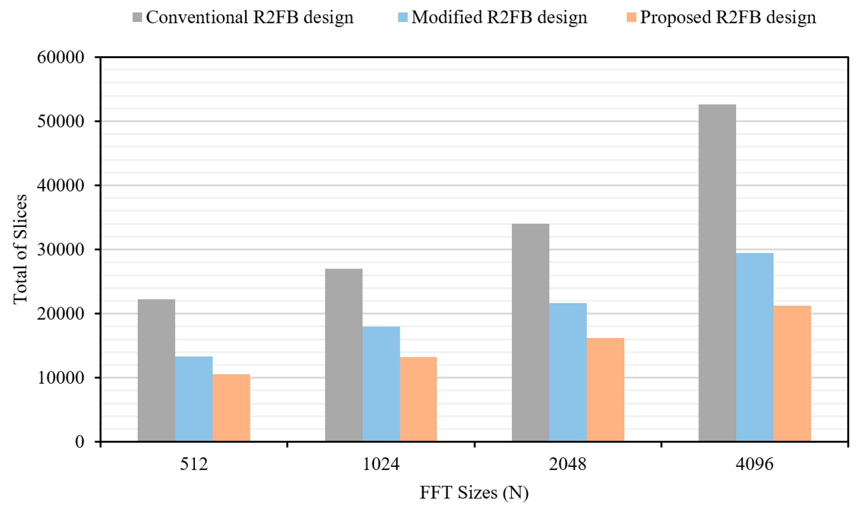
Table 5. In any hardware implementation of an FFT processor, the balance struck between the amount of resources consumed and the processing speed depends on the complexity of the architecture. The larger the number of FFT points, the higher the complexity. The extended results for the FFT processor with a various number of points are shown in
Table 6. An evaluation of the area on the chip, in terms of the number of slices, required by each of the aforementioned approaches for FFTs of various lengths on the same FPGAs is presented in
Figure 11. The proposed R2FB pipelined design requires the fewest number of slices for all cases of FFT computation in this study, and the resource utilization of the proposed design is also more optimized as the number of FFT points increases greatly. In the case of 4096-point calculation, the proposed R2FB pipelined FFT processor consumes about 59.56% less slices than the conventional design, which uses mainly the dedicated functional blocks in the architecture. The experimental results obviously show that the proposed FFT processor requires the fewest clock cycles, has faster execution time, and requires fewer hardware resources than the other systems for FFT computation. Compared to the other approaches, the proposed design reaches the goal of high speed, accuracy, and efficiency in resource utilization and area, and eliminates the need for a significant number of memory and DSP blocks on the chip.
6. Conclusions
In this paper, a R2FB pipelined architecture for the computation of FFT was proposed and its implementation on the Xilinx Virtex-7 FPGA kit was presented. The proposed design was verified and compared to existing approaches in terms of speed, the requisite hardware resources, area on the chip occupied by each design, and the hardware complexity. The feedback pipelined technique was successfully exploited for FFT implementation. The sharing of shift registers for storage between the inputs and outputs in a feedback architecture reduces the memory footprint of the proposed architecture and saves essential hardware resources. The m-CORDIC and CSD–based optimal hybrid rotation scheme was proposed to replace complex TF multipliers in the butterfly unit, resulting in faster convergence and fewer resource requirements with low hardware complexity. The improvements of the proposed design resulted in an FFT processor that requires only distributed logic resources on the FPGA instead of expensive dedicated functional blocks on a chip, making the proposed design flexible, fast, simple, low cost, and with reduced area on the chip. The achieved experimental results proved that the proposed R2FB pipelined FFT processor is better than existing FPGA-based designs in terms of speed by around 49% and in terms of resource utilization by about 51%, while delivering the same accuracy and using less area on the chip. The proposed design for the computation of FFT delivers significantly better processing speed and requires fewer hardware resources. However, since this design is based on the feedback pipelined technique and works on a single data-path stream that only allows sequential data processing at a rate of one sample per clock cycle, its computation throughput needs further improvement. To enhance the throughput of this design, multiple data-path, parallel processing approaches will be investigated in our future work.


