1. Introduction
A hardware trojan can be described as a malicious alteration or inclusion to an integrated circuit (IC) that will either alter its intended function or cause it to perform an additional malicious function. These malicious inclusions or alterations are generally programmed to activate only under a specific set of circumstances created by an attacker and are extremely hard to detect when in their dormant state [
1]. As technology advances, so does the demand for IC boards leaving many technology companies without the resources to produce secure enough ICs to meet current demands. This has pushed companies into the ‘fabless’ trend prevalent in today’s semi-conductor industry, where companies are no longer attempting to produce the goods in their own factories, but instead are outsourcing the process to cheaper factories abroad [
2,
3].
This growth brings with it a significant rise in the level of threat posed by hardware trojans, a threat that directly affects all companies concerned with products that utilise ICs. This encompasses many different industries, including the military and telecommunications companies, and can potentially affect billions of devices from mobile phones and computers to military grade aviation and detection devices, particularly at a time when wireless devices are being introduced as links in critical infrastructure, compounding trust and security issues even further [
4,
5]. It is also a direct threat to the already vulnerable Internet of Things, meaning that wireless-enabled household devices also become potential targets [
6].
The problem is such that even previously ‘reputable’ factories are vulnerable to attacks, since all that is required is one employee to alter the existing code to include a trojan [
7,
8]. As most IC designs are extremely large and contain a huge amount of hardware description, these inclusions are difficult to detect and the sheer size of the code can require many people having access to the code at production level.
Regarding military grade products utilising ICs, the problem of hardware trojans is critical with the threat level of the trojan being such that it could potentially be catastrophic. Malicious inclusions of code could cause life saving equipment to fail, missiles to lose control, and cryptography keys to be leaked. While incidents of hardware trojans, are not openly discussed there have been a few noted. In 2007, it was assumed that a backdoor built into a Syrian radar system was responsible for the system’s failure [
9]. There are also reports of trojans being used by the USSR to intercept American communications during the cold war [
3].
The problem is aggravated further still when considered in relation to the growth in production of counterfeit goods. Such goods may be produced in less than reputable factories, so the inclusion of malicious code in the production process is far from unrealistic [
10]. As counterfeit goods are not generally sold through trustworthy channels, it is impossible to recall products found to be unsafe or indeed to produce updated firmware to deal with emerging threats. This can expose consumers to a plethora of malicious attacks by hackers. For example, a trojan leaking cryptography keys in counterfeit IoT devices could potentially give hackers access to a network of devices that can be utilised in ‘Mirai’ like attacks and cannot be recalled or patched [
11].
In this paper, a hardware trojan is created and emulated on a consumer FPGA board. The experiments to detect the trojan in a dormant and active state are made using off-the-shelf technologies which rely on thermal imaging, power monitoring, and side-channel analysis. Furthermore, three attempts to detect the trojan are demonstrated and benchmarked. Finally, a state-of-the-art methodology is presented which allows accurate detection of the trojan in both dormant and active states.
Other researchers have attempted to detect trojans using similar techniques to the ones presented in this paper, using thermal imaging [
12,
13,
14] and side channel attack and power analysis [
15,
16] However, to the best knowledge of the authors this is the first manuscript successfully proposing a practical approach using off-the-shelf hardware for the detection of hardware trojans.
The rest of this paper is organised as follows,
Section 2 provides an overview of the different hardware threats, the industries affected and a detailed hardware taxonomy, while
Section 3 provides an overview on the testing methodology, the design of the trojan, its functions and details of its implementation. In
Section 4 an overview of the different techniques used to detect the hardware trojan are provided.
Section 5 describes the results obtained using the different off-the-shelf devices. The results and techniques are further discussed in
Section 6 and the paper finishes in
Section 7 with the conclusion.
2. Background
Whilst the ongoing war between hackers and software developers has been raging since the 1980s, the underlying hardware being utilised was always considered to be secure [
17]. Over the last decade, however, the technological progress has been such that the demand for IC boards has grown to unprecedented levels. To cope with such demand, many technology companies have evolved into the so-called ‘fabless’ companies, meaning that their designs are outsourced to cheaper, usually foreign, foundries for production [
18]. As the number of companies involved in the production chain has grown, so have concerns, and the problem of hardware trojans has escalated.
As the full potential of the threat posed by the hardware trojan has been realised and acknowledged by the electronics industries many different conspiracy theories have emerged. Unfortunately, those theories are not in nature groundless or out-with the realms of the possible. In fact several of them have already been instantiated. One such rumour of ‘kill switches’ being hidden in commercial processors was confirmed by an anonymous U.S. defence contractor who indicated the culprit to be a ‘European Chip Maker’ [
17]. The potential consequence of the existence of such a switch could be catastrophic. Indeed, as previously highlighted, this particular hardware trojan was blamed for the failure of a Syrian radar to detect an incoming air strike [
19].
2.1. The Threat of the Hardware Trojan
2.1.1. At Design Level
The complexity and cost of the design of ICs has grown exponentially over the last decade as the semiconductor industry has scaled to sub-micron levels. A typical IC board will go through a rigorous process consisting of several stages.
Firstly, the specifications must be translated into a behavioural description, usually in a hardware description language such as Verilog or VHDL. Once this has been completed, the next phase is to perform synthesis to transform the behavioural description into a design implementation using logic gates such as a netlist. Once the synthesis has been completed, the netlist is implemented as a layout design and the digital files are passed to the foundry for fabrication [
17].
As well as outsourcing the production of ICs, many companies are also purchasing third party intellectual property (IP) cores, and utilising third party Electronic Design Automation (EDA) tools. Each use of a third-party software presents a new opportunity for attacks such as hardware trojan insertion, IP piracy, IC tampering, and IC cloning. Although these attacks are all of importance, the hardware trojan is by far the most dangerous attack, and, as such, has garnered much attention [
17].
2.1.2. At Foundry Level
As semiconductor technology has advanced, the cost of owning foundry has increased dramatically. In 2015, the cost was estimated to be in the region of 5 billion USD [
20]. As a direct result of this, many companies can no longer afford to fund the production process from start to finish, and are outsourcing their production to cheaper foreign foundries [
17].
Whilst undesirable modifications to ICs should ideally be detectable by pre-silicon verification and simulation, this would require a specific model of the entire IC design and this is not always readily available particularly where third party IP cores or EDA tools have been used. In addition, large multi module designs are rarely compliant with exhaustive verification [
21].
Post silicone approaches to design verification include destructive de-packaging and reverse engineering of the IC. However, current techniques do not allow destructive verification of ICs to be scalable [
22]. It is also possible for an attacker to infect only a portion of the produced ICs, making these tests futile [
23].
Most post silicone logical testing techniques are also unsuitable for detecting hardware trojans. This is attributed to the stealthy nature of the hardware trojan and to the large numbers of differing taxonomys that can be employed by the attackers. Most hardware trojans are programmed to activate under a specific set of conditions, and a skilled attacker would ensure that these conditions were undetectable by the testing routine. This is particularly true of trojans targeting sequential finite state machines [
24].
2.2. Industries Affected
2.2.1. Military
Hardware trojans are a huge threat to many industries. However, security conscious industries, such as the military, are in a particularly high risk bracket and defence departments are very aware of this. The U.S. Department of Defense (DoD) has created a “Trusted Foundry Program” to ensure its military equipment remains free of hardware trojans by using only accredited foundries. This means that only American foundries which are located on the Americal soil and which underwent the strictest vetting process are allowed to work on the chips for the U.S. DoD. In addition to vetting the foundries, close attention is being paid to the other links in the design and supply chain [
9].
While this approach may seem effective, it has its limitations. The majority of western foundries are woefully behind their foreign counterparts when it comes to the level of technology they can provide. This seriously limits access to more advanced chips which are required for modern avionics and weapons systems [
9].
2.2.2. Financial Infrastructures
In 2008, an experiment was carried out by the University of Illinois in which researchers designed and inserted a small backdoor circuit that gave access to privileged areas of the chip’s memory [
9]. This trojan could then be used to change process identifiers allowing attackers to access all data contained on the chip’s memory. It is easy to see why this could be catastrophic in settings such as critical infrastructures. Trojans such as the one described are usually small and are nigh impossible to detect.
2.2.3. Consumer Industries
Security industries are not the only potential targets of a hardware trojan attack. There exists the possibility of utilising a hardware trojan by rival firms in industrial sabotage. The potential damage that could be caused by such an attack could be enough to disable even global corporations, particularly in industries such as telecommunications.
Aside from industrial sabotage, the potential threat to consumer privacy is also of major importance. Devices such as smartphones and tablets could be targeted by trojans designed to leak private encryption keys or private information [
9].
2.3. Hardware Trojan Taxonomy
Although the terms and definitions used to classify different hardware trojans can vary between different authors, the general taxonomy is universally agreed to consist of the physical representation, the behavioural phase or trigger, and the action phase in which the trojan will execute its payload.
2.3.1. Physical Representation
When designing malicious circuitry, there are several characteristics that must be considered. The first of these characteristics is the ‘type’ of the hardware trojan, which can be defined as functional or parametric.
A trojan is categorised as functional when the attacker adds components such as logic gates to the original design. Accordingly, the deletion of components to cause a malicious function would also place it in this category [
25].
If the attacker creates the trojan through the modification of the existing code, then it will be classified as a parametric. Typically, this can be achieved by thinning wires or weakening transistors and flip flops. This type of trojan is notoriously hard to detect as the alteration can be minuscule.
The next physical characteristic the attacker would have to consider would be the size of the hardware trojan. In this context, the size refers to the physical extension of the hardware trojan or the number of components it consists of. In case of a large trojan consisting of many components, an attacker can distribute these across the IC, placing components where they are necessary to execute their payload in accordance with the functions of the hardware trojan. This is known as loose distribution [
25].
In contrast, a smaller hardware trojan consisting of only a few components allows for the components to be placed together as they will occupy only a small part of the layout of the IC. This is known as tight distribution.
On rare occasions, a determined attacker could regenerate the layout to encompass the hardware trojan, moving the components of the IC to accommodate the components of the hardware trojan. This is referred to as a structural alteration [
25].
2.3.2. Activation Characteristics
Typically, a hardware trojan will be condition-based, meaning that its activation will be dependent on a trigger defined by the attacker. The trigger itself will generally consist of either a predefined input pattern, or specific internal logic state, or counter value, and can be triggered both internally and externally.
An externally triggered hardware trojan will usually consist of malicious logic within the IC that utilises an external sensor such as a radio antenna. The attacker will then communicate via the compromised component enabling them to trigger the antenna. It is easy to see why this can be extremely dangerous when it comes to security conscious industries such as the military. It is not out-with the realms of the believable to postulate that an attacker could feasibly re-route or switch off a missile via a radio signal as suggested in [
22]. Conversely, an internally triggered hardware trojan will look within the circuitry for the set of conditions that will cause it to activate. A typical example of this would be a countdown logic.
In contrast to the condition-based trojan that will only activate when its trigger conditions are met, the “always-on” trojan is active from the moment of insertion, and relies on internal signals. This type of hardware trojan is generally split into two categories; combinational and sequential. A combinational trojan will activate upon detection of a specific set of circumstances within the internal signals of the IC. Sequential trojans will also monitor the internal signals of the IC. However, instead of looking for a specific condition, they activate when a specific sequence of events occurs [
26].
2.3.3. Action Characteristics
The action characteristics of a hardware trojan refer to the effect the trojan will have on the execution of its payload. Hardware trojans will typically fall into one of two categories: implicit or explicit [
27]. Implicit trojans will not change the board’s circuitry of the IC; instead, they will perform their malicious function in tandem with the intended function of the board. This makes these trojans easier to detect as they tend to cause small path delays on activation and consume more power whilst active.
In contrast, an explicit trojan will change the function of the board’s circuitry on activation. This can come in the form of a signal alteration or even leaking of information via predefined board pins. These trojans tend to cause distinct path delays as well as large changes in circuit’s capacity [
27].
2.4. Hardware Trojan Detection
Detecting a hardware trojan requires overcoming numerous challenges. Namely:
Handling large architectures.
Being non-destructive to the IC.
Being cost effective.
Ability to Detect trojans of all sizes.
Authenticating chips in as small a time frame as possible.
Dealing with variations in manufacturing processes.
Detecting all trojan classifications.
Detecting trojans in a reasonable time frame.
To the best of the authors’ knowledge, there is no single method capable of detecting all types of hardware trojans, nor overcoming all the challenges described here-above. Over the years, several methods have been developed to detect different types of trojans. These methods are described here-after.
2.4.1. Physical Inspection
One of the most obvious method of detection is physical inspection of the board itself. This method is sometimes classified as a failure analysis based technique. Those techniques usually comprise two steps: (1) cutting and lifting the molding coat to expose the circuitry; and (2) performing various scans [
25,
28].
2.4.2. Functional Testing
Often referred to as Automatic Test Pattern Generation (ATPG) this technique is more commonly used to locate manufacturing faults; it has been shown to be effective in detecting hardware trojans. ATPG involves inputs of ports are stimulated and then the output ports are monitored for variations that may indicate a hardware trojan has been activated. Functional testing techniques can also be useful when attempting to determine the trigger patterns of conditional trojans [
25,
27].
2.4.3. Built-In-Self-Test Techniques
Built-In-Self-Test (BIST) techniques are commonly used to detect manufacturing faults and are present in many chips. If unknown or malicious logic is detected during these tests a bad checksum result is given, although designed to detect manufacturing faults on some occasions these tests can detect hardware trojans [
25].
2.4.4. Side Channel Analysis
Side channel analysis techniques are some of the most commonly used procedures in hardware trojan detection. These techniques generally measure signals such as power and path delay, looking for fluctuations potentially caused by trojans. Side channel analysis can have a high success rate as even in a dormant state the trojans trigger signal will cause some current leakage [
25].
3. Methodology
In order to carry out the investigation our trojan was designed and loaded onto an Basys 3 Artix 7 FPGA board. Three different detection techniques are demonstrated, the first utilises power analysis techniques as well as side channel analysis, allowing security investigators to measure both the power variance, traces and current leakage, followed by a concentrated heat measurements using an infrared thermometer, and finally a thermal camera test is carried out. The three experiments are carried out using off-the-shelf hardware and are applied to both the trojan-free and trojan-inserted designs. Attempts are then made to detect the trojan in its dormant form. While in in their dormant form trojans do not perform any malicious actions, however, wait to be activated, through an activation signal, this can be done through the push of a button, or through a specific set of instructions. It is however important to be able to detect trojans in their dormant form, before they activate and perform malicious actions. In the last experiment, the thermal camera is also used to measure the impact of the trojan in its active form.
Table 1 provides information on the type of devices used to carry out the different experiments.
3.1. Design
Whilst there is much literature available on the topic of hardware trojans and many papers aimed at the various taxonomies of hardware trojans, there are few practical examples to be found. This paper aims at providing thorough details on the creation of a tailored hardware trojan. The factors considered in the experiments and the resultant decisions are shown in the list below;
- Main Function
The algorithm as a main function running continuously. This function serves by providing information on the board, and executing tasks in a round robin fashion, these tasks run in a loop, this ensures steady power readings.
- Physical Representation
The trojan designed for the experiments is in the form of a functional trojan as opposed to a parametric trojan. Functional trojans are categorised as a malicious inclusion of components and code as opposed to an alteration to existing code.
- Physical Size
The trojan designed for the experiments is required to be small and consists of no more than three components, this allows a tight distribution on the board. The creation of a complex design is deemed to be out of the scope of this paper.
- Characteristics
The trojan is activated by an external trigger to preserve the integrity of the testing results. This provides assurances for the different test results, and allows the monitoring of the free, dormant, and active states. This test falls within the parameters of a conditional trojan.
- Malicious Function
The trojan is required to have a malicious impact on the board, while more advanced functions such as the leaking of cryptography keys are within the scope of this investigation, simpler functions are privileged to demonstrate the process. Two distinct functions are chosen, the first one causes the board to overheat, while the second one performs an unwanted action on the board.
The design was carried out using the Vivado WebPACK Design Suite, this allowed for high level design, synthesis and implementation.
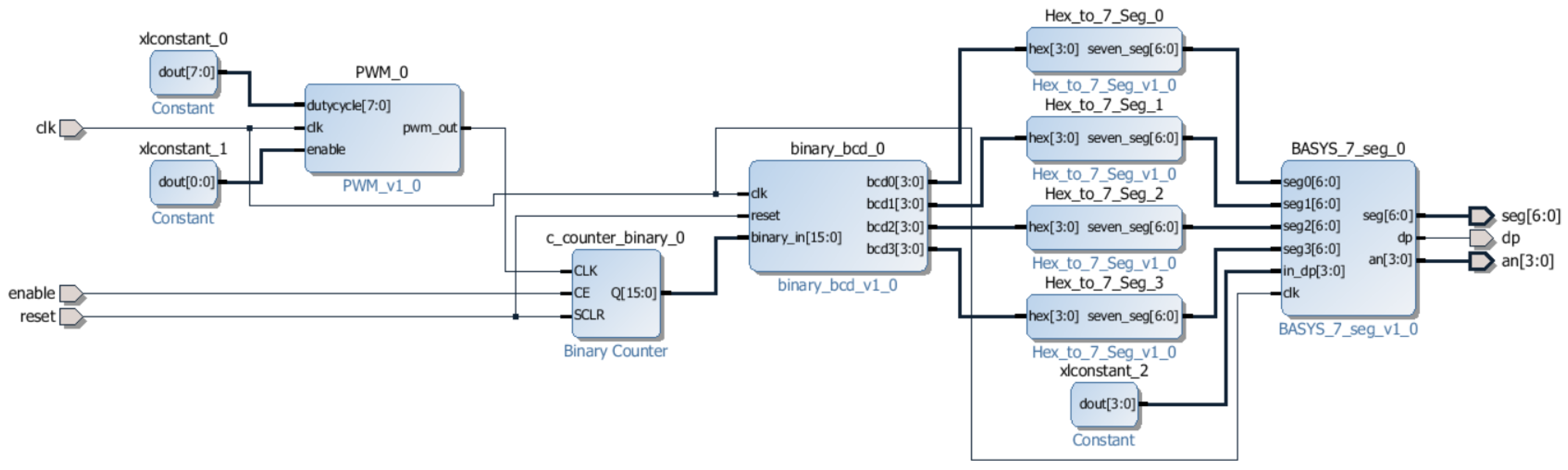
Currently the use of third party Intellectual Property (IP) Cores to construct large and complex designs is standard practice industry wide. An IP core is a block of logic or code that can be utilised in the design of an ASIC or FPGA, most common components can be found the form of an IP Core and this method of design drastically reduces the amount of time the designer spends writing code. It is equally likely that an attacker inserting malicious code would have had the skill to create and insert their own hand crafted code. A block diagram is shown in
Figure 1, the block diagram represent the counter without the trojan inserted.
3.2. Trojan-Free Design
The main function of the trojan-free design was decided to be a counter program, counting from 1 to 9999 on a loop and output to the four seven segment displays present on the Basys 3 board. The components used in this design operate at a steady rate, this ensures steady power tests taken whilst performing side channel analysis on the clean board, thereby guaranteeing that any fluctuations detected on the infected board are indeed caused by the presence of the trojan. The trojan-free design requirements for the counter can be found below;
The refresh rate for the 7 segment displays is set to 5000 Hz
The design utilises all four 7 segment displays
The 7 segment displays output a count that beginning at 0 and incrementing up to 9999
Upon reaching maxcount of 9999 the displays resets to 0
The counter is enabled via a switch
The counter can be reset via a pushbutton
The counter will count at a rate of 5 Hz
After the final configuration, it was a matter of creating a top level VHDL wrapper to contain the inputs and outputs of the block design. The wrapper file maps all the I/O ports of the physical board with the I/O described in the constrain file. Finally, the constraints for the project needed to be added to successfully synthesise and implement the design. Constraints files are used to map the input and output ports to specific pins on the FPGA board and can be easily configured by uncommenting a master file and editing the port names to reflect those of your design.
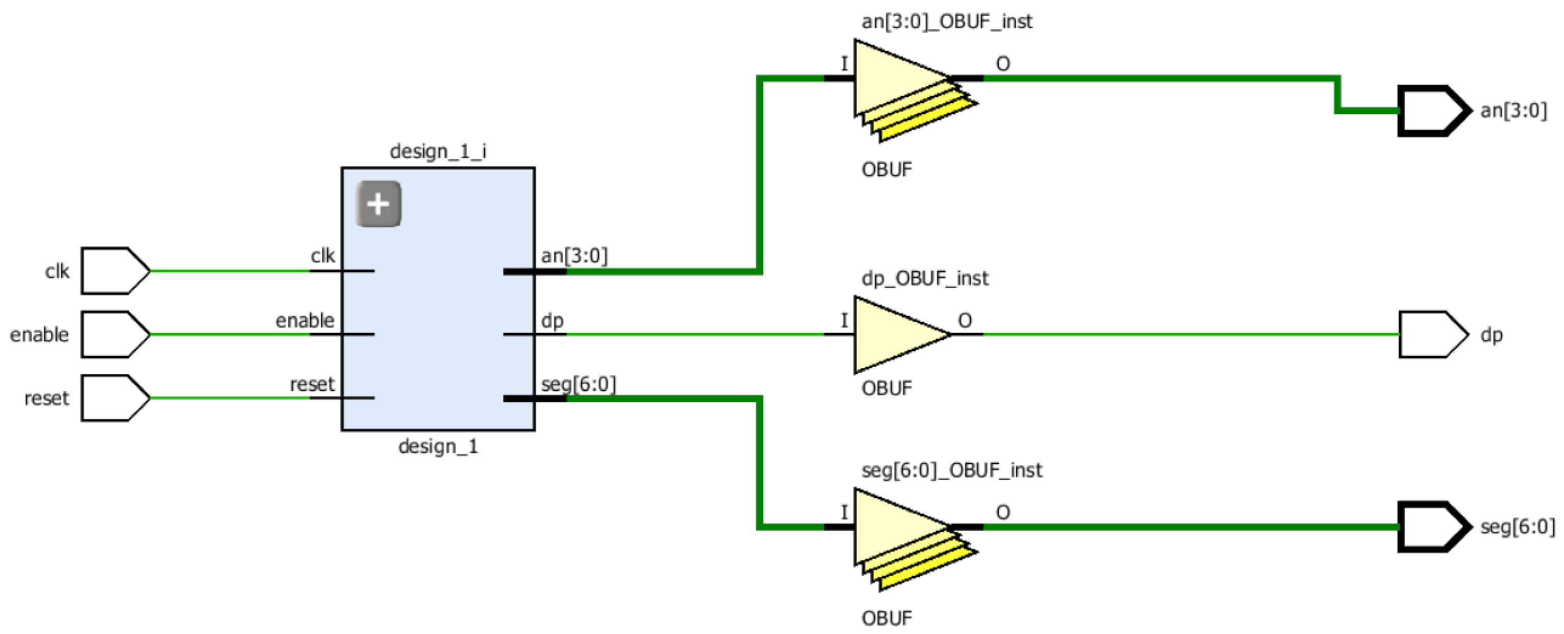
Figure 2 shows the trojan-free elaborated design schematic. The schematic is based the RTL file. The schematic identifies pieces of code representing hardware structure. The code further converted (Synthesis) into “technology cells” abstracting elements such as multiplexer, adder, etc….
3.3. Unsigned Multiplier
As previously discussed the trojan code used in this project was handcrafted to mimic the techniques that would be used by an attacker, although it is possible that malicious code could be contained within a third-party IP core.
The design to be used for the trojan is in the form of an unsigned multiplier that operates on a combination of buttons and switches and output onto the LED. The required inputs of both switches and a button can be said to represent the usually hard to guess trigger. These inputs are often used in conditional trojans.
The trojan was designed with these specifications in mind.
There shall be 15 input switches and 1 input button
There shall be a start button and a reset button
The multiplier will output in binary via LEDs
The multiplier shall utilise two finite state machines
The multiplier should have a malicious effect on the board
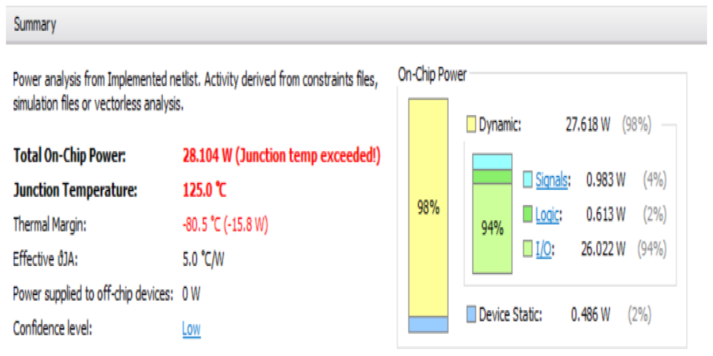
FPGA boards do not tend to contain many dedicated multipliers with the Basys 3 containing only four. This means that when creating a design that requires a multiplier most designers will compensate for this by creating their own. As such, the presence of this code would not be likely cause suspicion. The junction temperature of the board is the highest temperature that a board can operate safely at, it is calculated using Equation (
1).
Let
be the ambient temperature expressed in °C, let
be the Junction-to-ambient thermal resistance, let
be the core power, finally let
be the junction temperature. The relationship between the thermal parameters of the board can be expressed as show in Equation (
2), let
be the junction-to-ambient thermal it defines the difference between junctions temperatures and the ambient temperature when the device dissipates 1Watt of power, hence is expressed in °C/W resistance, let
be the junction-to-case thermal resistance and is expressed in °C/W and
be the case-to-ambient thermal resistance and is expressed in °C/W.
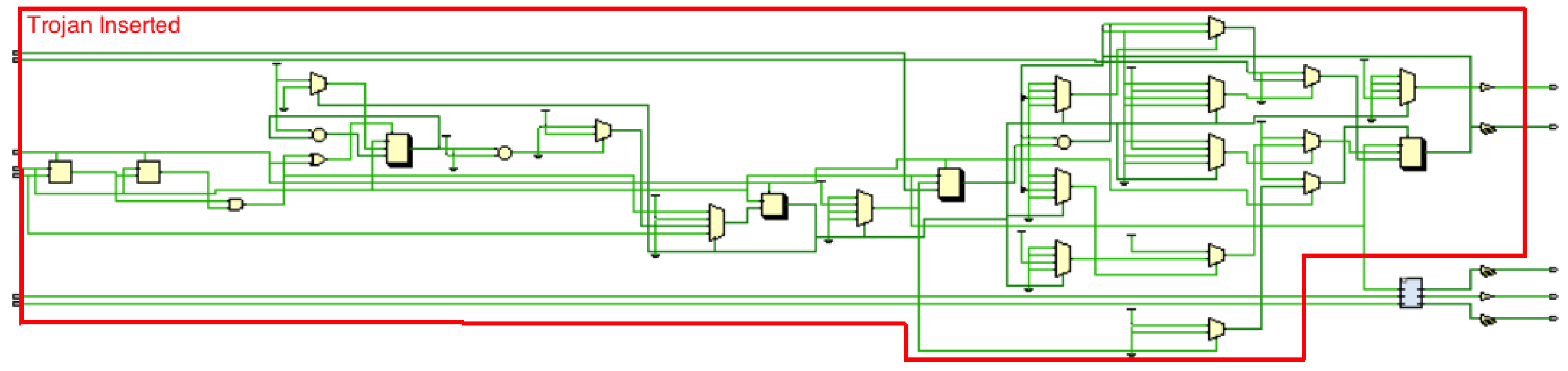
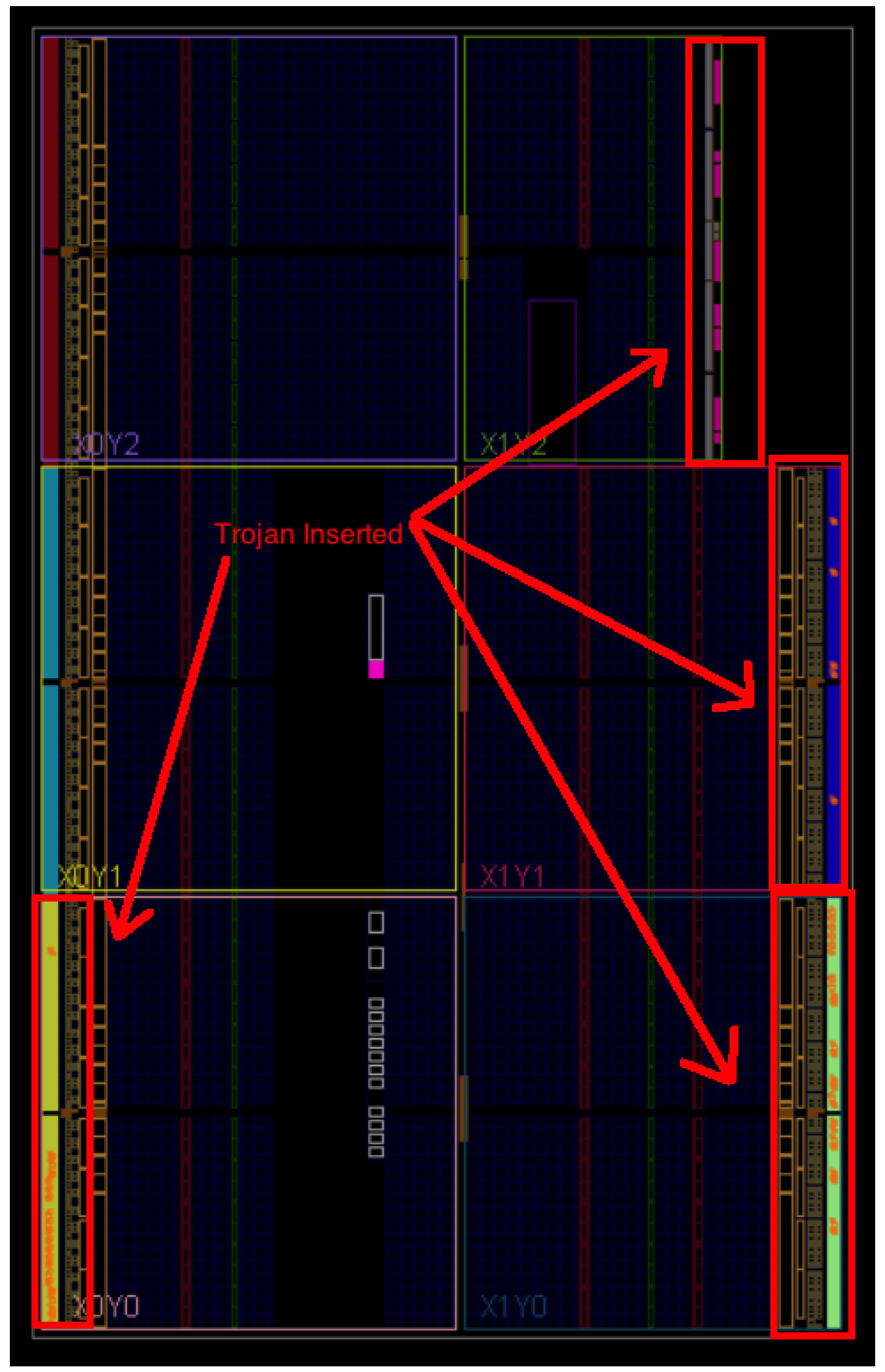
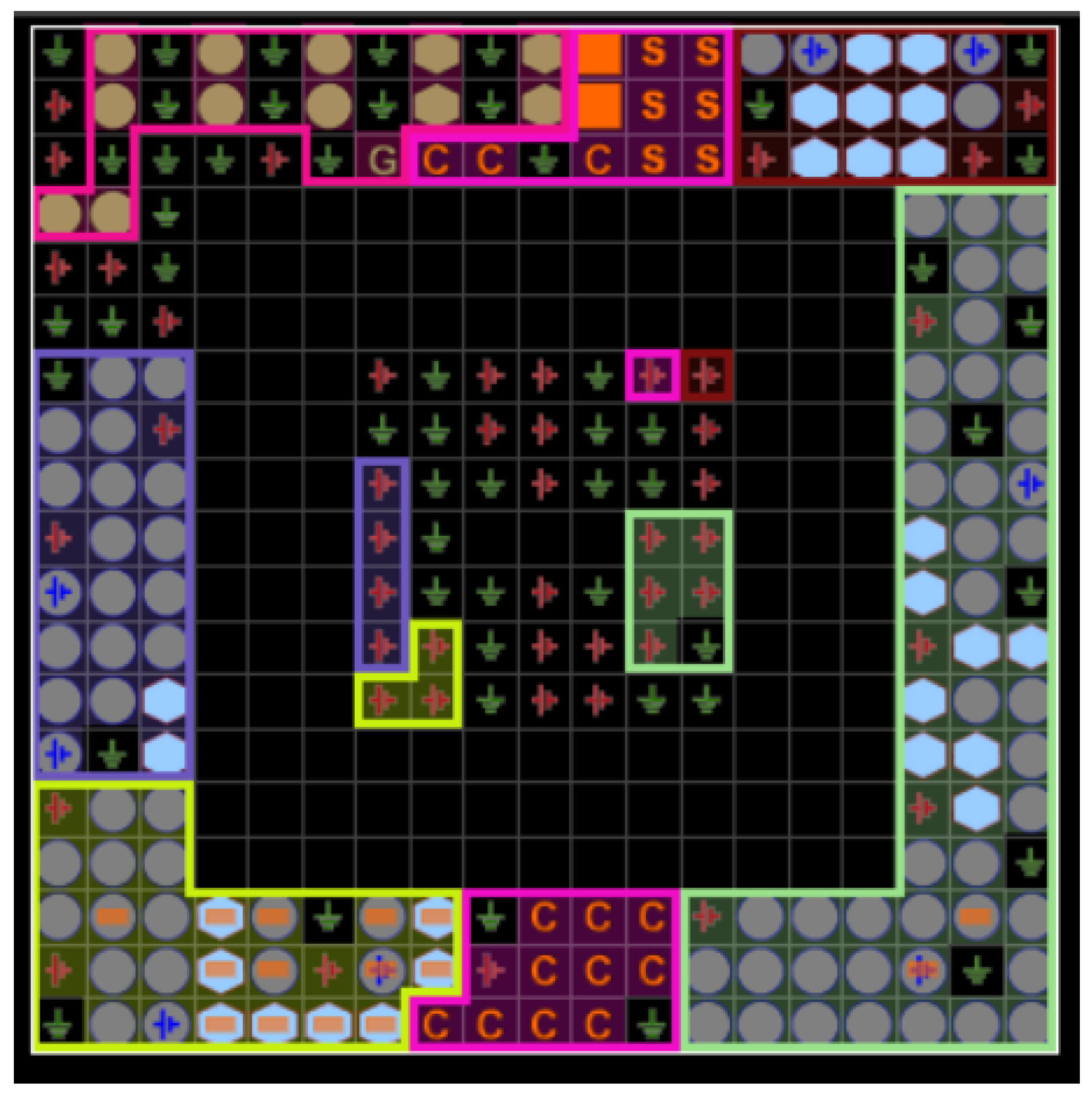
The design for the trojan also utilises two finite state machines, This is necessary for the multiplier as it requires several inputs. This can be seen in
Figure 3 (Highlighted in Red). For the purposes of this trojan a Mealy machine was deemed to be most appropriate. Generally Mealy machines have fewer states that Moore machines, the output changes at the clock edges in a Mealy machine and react faster to inputs. This fits well with the requirements of the trojan as it must have several inputs.
Once the trojan designed the next step is to create a working constraints file as this is necessary to test the functionality of the trojan.
3.4. The Trojan
Having designed and built both the counter and multiplier circuits the next step is to integrate the code from the multiplier into the top level VHDL wrapper created for the counter circuit. The counter signal is asynchronous. The counter activates on the first flip-flop. The subsequent flip-flops are clocked by using the output of the previous flip-flop.
The additional ports required by the multiplier was to be added to the original design for the counter. Whilst this is straight forward for most of the ports, the clk port in the multiplier was deleted as there was already a clock in place and they had been set to the same value, meaning that the “trojan” was now utilising the clk port of the counter.
The second amendment that had to be made was the reset port for the multiplier, as again the counter already had a reset port. While it may have been possible to allow both to use the same button, the ability to reset the trojan alone is important to the integrity of the testing and results. To circumvent this the reset port for the multiplier was renamed as and would be mapped to a different push button. As the multiplier is unsigned it was also necessary to include the and is working synchronously.
As the code to be inserted was still referencing the reset port it was necessary to go through all the processes and change the reset port to the newly created port. The next step was to insert the code for the processes that would be utilised by the trojan, this code was again inserted into the architecture body of the program.
Finally, the constraints file was updated to include the ports utilised by the ‘trojan’. At this point it became evident that there were not enough input switches to accommodate both designs, the multiplier requires all sixteen switches as it takes inputs in binary form and the counter also requires an input switch.
As the switch was essential to the counters enable signal, a push button would only increment on each button press, the multipliers was mapped to a push button. This made the input pattern required by the trojan a combination of buttons and switches followed by a specific button press.
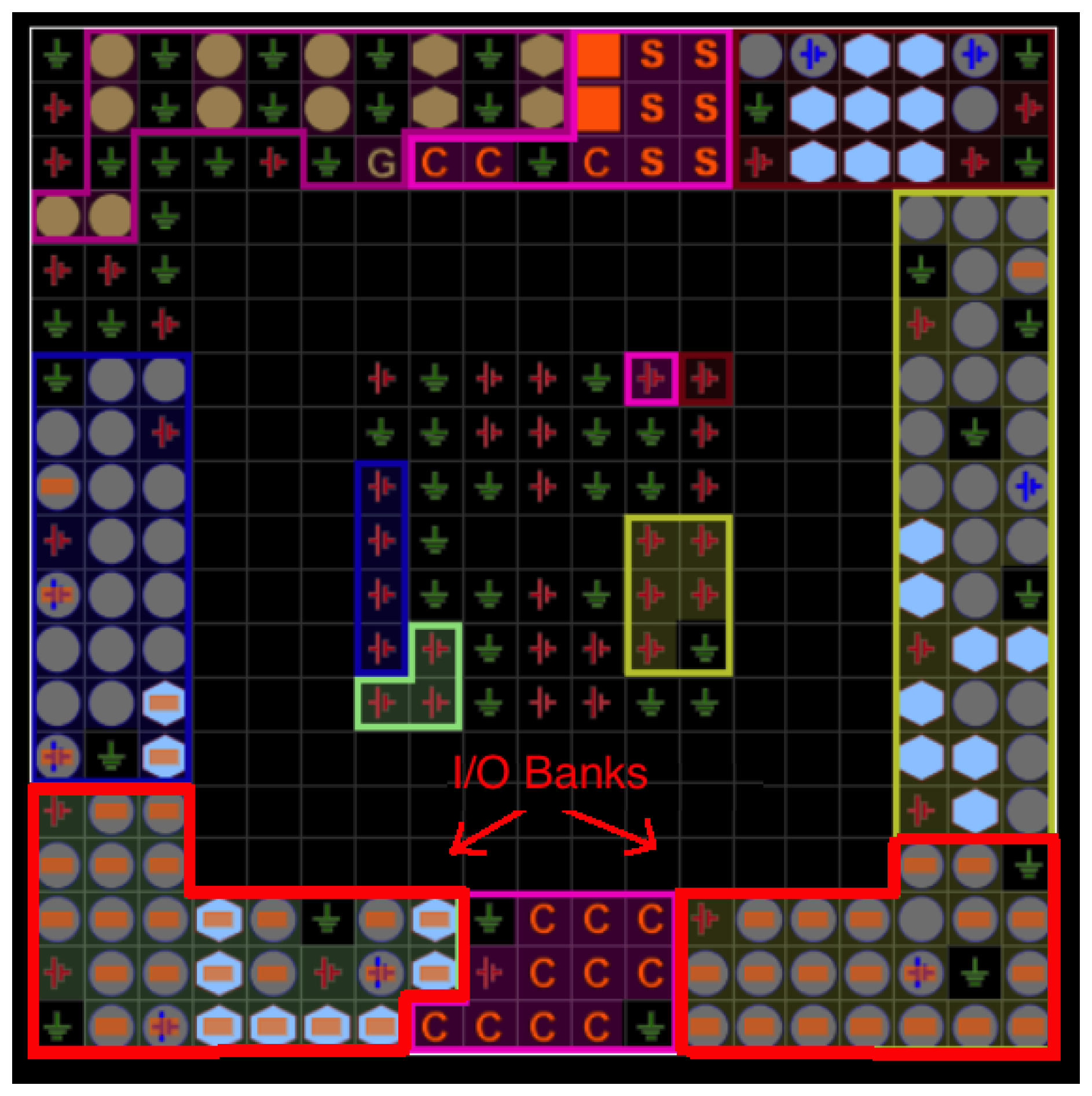
3.5. Elaborating the Designs
Although the code has now been created for both the trojan-free and trojan-inserted boards there are several more phases to the process of creating the final bitstream file that will be used to program the board. The first of these stages is that of elaborating the design. The elaboration process essentially takes the code provided and changes it from RTL into a variety of visual representations.
3.6. Synthesising the Designs
Synthesis refers to the process of transforming the design from an RTL design into a gate level representation. Synthesis is run after the relevant design and constraint files have been added to the project and will only be successful if the files added contain no syntax or constraints errors. Following a successful synthesis, it is possible to access the synthesised design and view the schematics of the design along with various other representations.
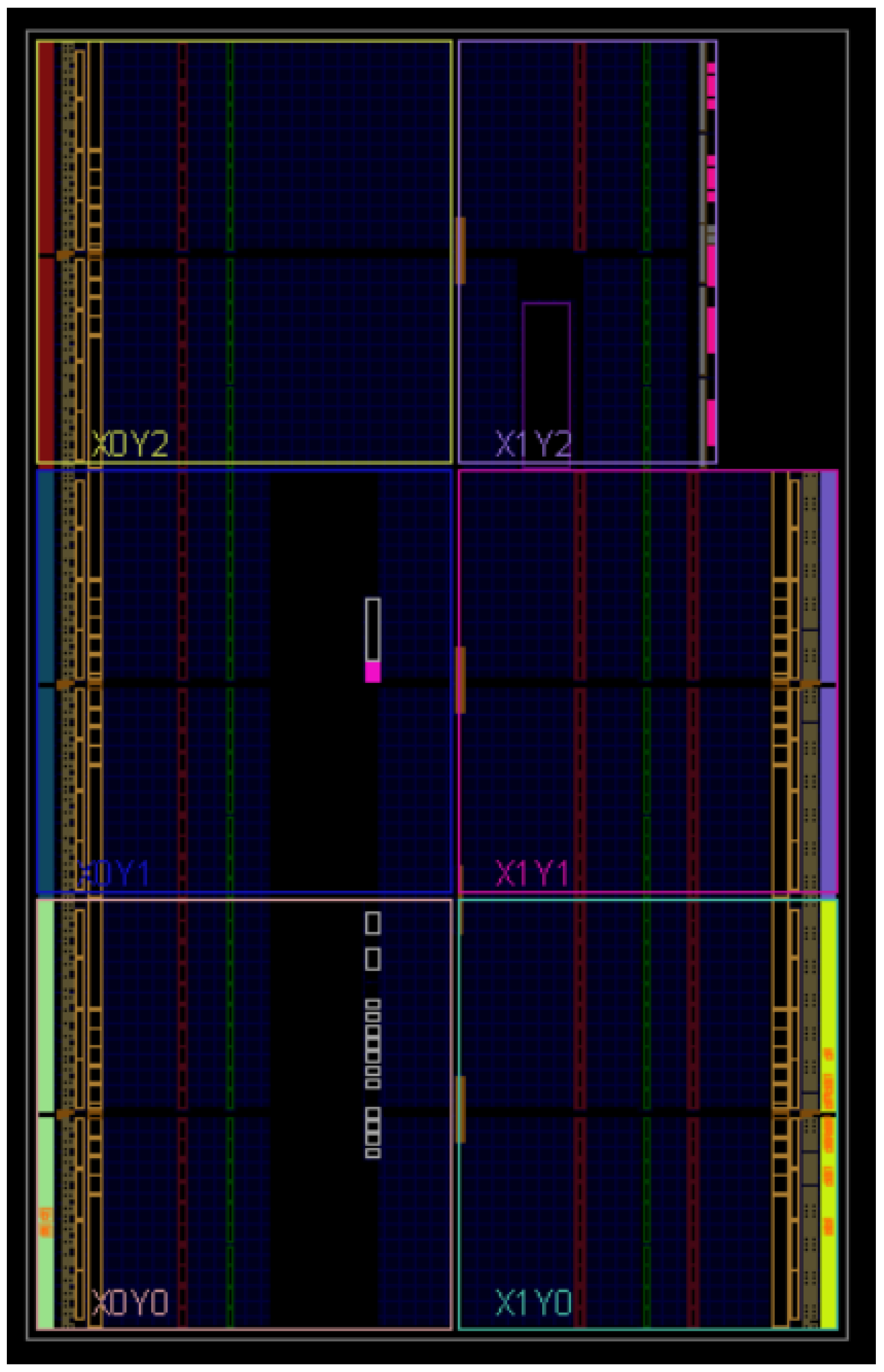
3.7. Implementing the Designs
Having successfully synthesised the design the next step was to run it through the implementation process. Implementation is essentially equivalent to routing and placing the design on the board. The implementation process places the netlist onto the board in a virtual environment and connects them in accordance with the constraints file. If it is possible to safely place the design on the board and it will then be possible to generate a bitstream file which can then be placed on the FPGA board.
3.8. Generating Bitstream File and Programming the Board
Once the design has passed the required phases it is possible to generate a bitstream file, this is the file that used to program the FPGA board.
Before programming the board, it was necessary to ensure that the board was correctly configured. The board can be programmed to accept a file or to perform a Built In Self Test (BIST), by default it is set to BIST to enable programming mode on the board.
4. Malware Detection Methodologies
The scenario presented in this manuscript for the trojan detection assumes that the board has been infected during production, hence the full design of the board is known. It is also assumed that we have a free trojan board at our disposal. This could be a prototype.
4.1. Side Channel Analysis
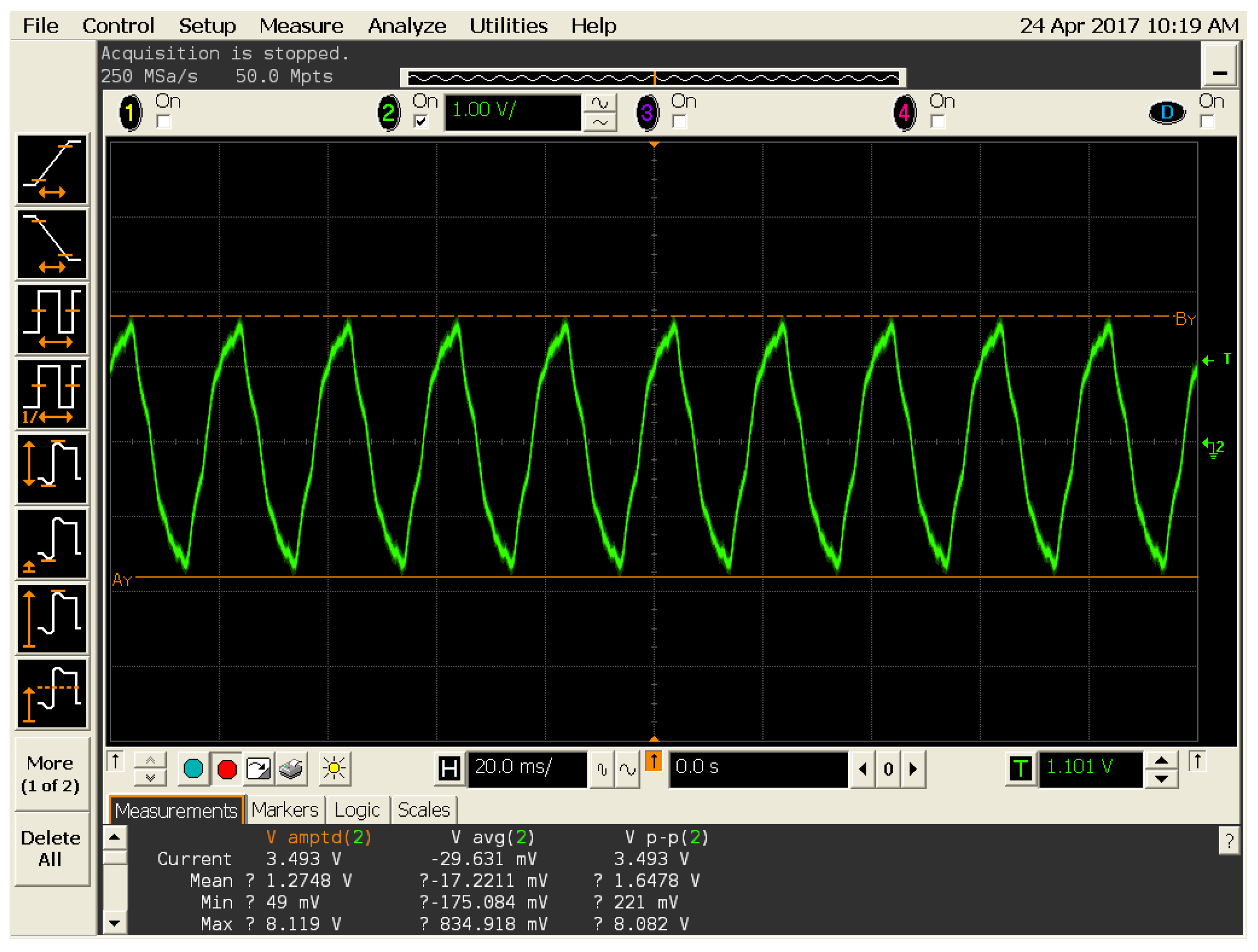
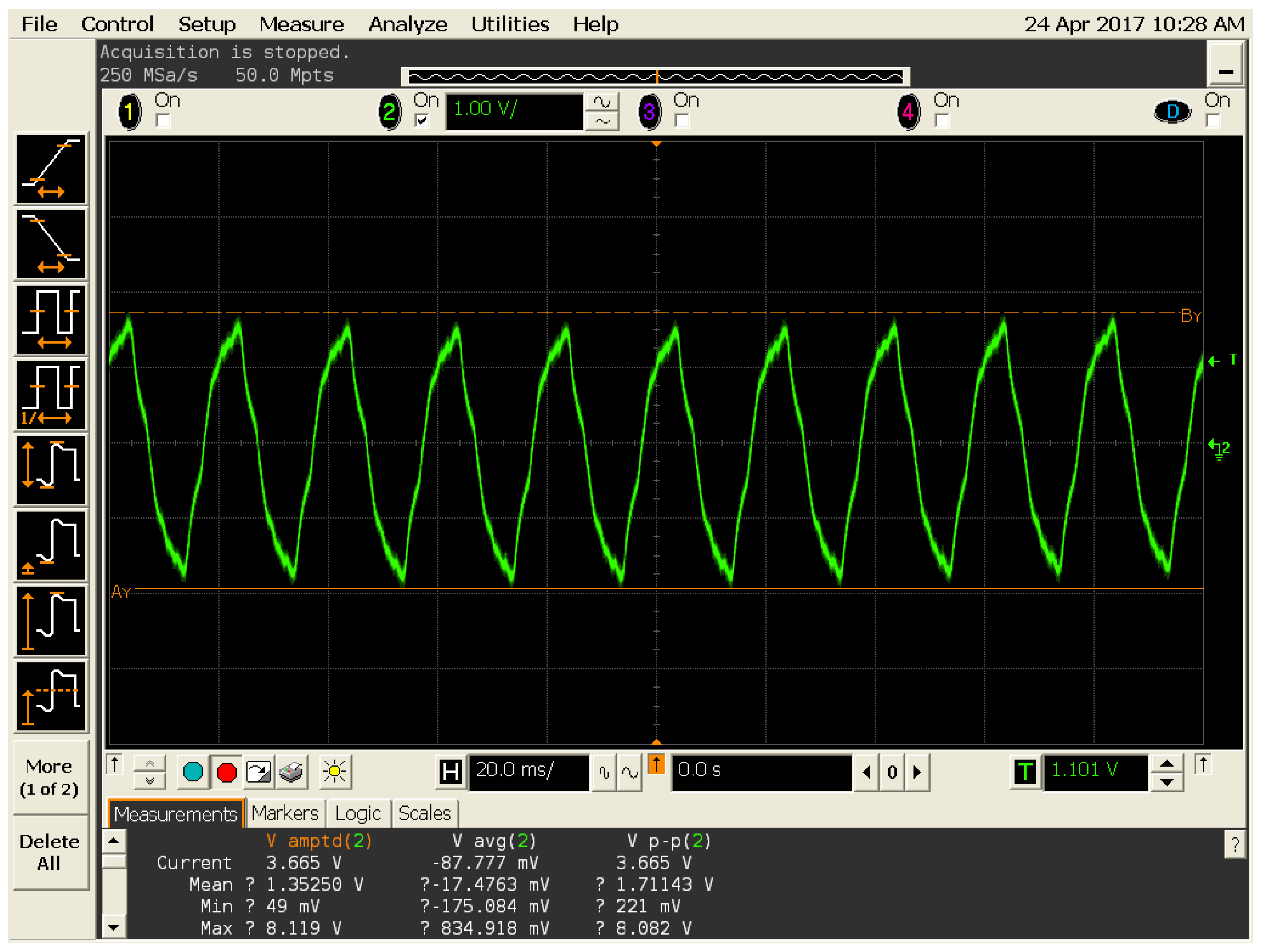
Side channel analysis techniques are employed in order to detect fluctuations in variables such as power and path delay, for this investigation it was decided to test power levels using an oscilloscope.
Two oscilloscopes were used for the investigation, the first one was an Infinium series 1 GHz 4 GSa/s oscilloscope from Agilent. While the second one was an OpenScope 2 scope channel with 12 bits at 2 MHz as shown in
Table 1.
By analysing the schematics of the Artix 7 board, we identified the power in/out pins to the FPGA chip. As these pins are likely to be utilised by any design they were most likely to exhibit power fluctuations caused by the trojan. In a real world scenario, the authors of a circuit to be able to locate and test multiple pins and capacitors against a golden design in order to detect a trojan.
In order to detect power fluctuations, we set a trigger on the oscilloscope. The trigger allows the user to set a limit on readings. If the voltage measured goes above the set trigger level then the oscilloscope will stop the measurement. The trigger can be dragged and to fit measurements for pins on the trojan-free board, if the trojan boards readings exceed those of the trojan-free board, we could assume that the board was infected. This experiment was realised with the two oscilloscope, over fifteen times, to ensure accurate readings.
4.2. Temperature Readings
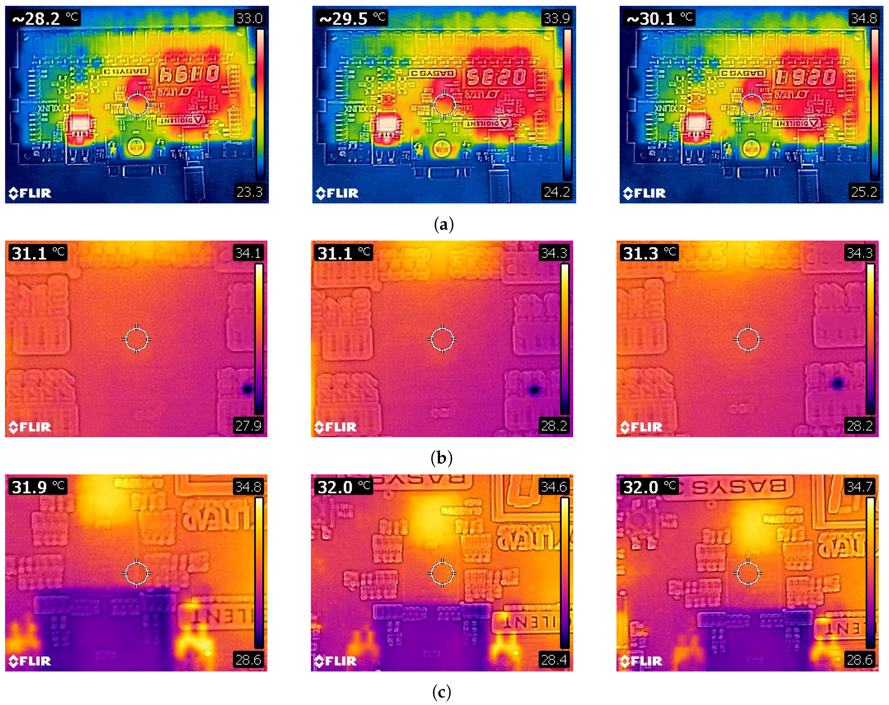
In order to obtain temperature readings during the testing phase of the investigation an infrared thermometer and a heat camera were used on the boards Artix 7 FPGA chip. With the trojan active, it is assumed that during normal operation, the trojan-free board will consume less power, hence the chip will be cooler. Moreover, even in its dormant form fluctuations caused by the presence of the trojan may be detectable.
The Infrared Thermometer Gun used is described in
Table 1. The thermometer is an infrared thermometer which utilises sensors to acquire and measure infrared radiation from the surface it is aimed at, and from this radiation it determines temperatures. The device can detect and record temperatures ranging from −50 °C to +380 °C and as such it fits within the expected temperature range of the FPGA chip. The FLIR C2 heat camera used is described in
Table 1. The Flir C2 Camera is a standard off-the-shelf heat camera, with a sensitivity of 0.10 °C and works within the −10 °C to +150 °C (14 °F to 302 °F) The IR sensors provides 80 × 60 (4800 measurement pixels) and works within as spectral range of 7.5–14
m.
4.3. Testing Process
There were several factors considered for the testing process, firstly after each test the board is left to cool down for fifteen minutes before being re-tested. This ensure that the results are not skewed by remnant heat. Misleading results could potentially affect the camera and heat gun readings, hence the cool down period. Secondly, ten readings where taken on both boards with 30 s intervals. All results are then compared. The infrared thermometer is being held at 15 cm from the board for all readings, while the heat camera is held at 20 cm from the board.
6. Discussion
In this section, the results are discussed in detail. Our test provided the corner-stone for hardware trojan creation and detection using off-the-shelf technologies against a golden model. The practical work presented in this manuscript demonstrated the feasibility of hardware trojan detection using side-channel attacks, a heat camera, and a heat gun. While the settings of these tests where pre-defined, it is not un-common for this type of work as suggested in [
30].
The three tests required to provide readings between the trojan-inserted and trojan-free boards w to determine the existence of the trojan. In an industial setting, it is unlikely to suffice, however, the results presented in this paper provide evidence that trojans can be detected using off-the-shelf hardware due to the increase in accuracy of the devices and the access to technologies previously reserved to specialized industries, and which are now becoming commodities.
6.1. Thermal Camera
The thermal camera provided extensive results of the three stages of the trojan. This technique provides a good visual representation, demonstrating the presence of the trojan on the board. However, as aforementioned, in order for the camera to provide accurate results a trojan-free board is needed. While this technique is accurate, when used as a stand-alone test it requires the camera to be well calibrated in order to provide the best results. In the setting presented in this manuscript, both the trojan taxonomy and its purpose where known, hence, during this white-box testing, the full calibration of the camera could be overlooked.
6.2. Heat Gun
The heat gun was able to demonstrate the presence of a a hardware trojan in different settings, while the heat gun was accurate enough to detect the temperature variation, as for the heat camera, this test requires to have free trojan board for comparison. As aforementioned, this is not uncommon for this type of work [
30]. While the results provided by the heat gun are notable, they differ greatly from the thermal camera. It was expected from the start for the thermal camera to outperform the heat gun, due to the low accuracy of the heat gun.
6.3. Side Channel Analysis
The side channel analysis techniques was employed in attempts to locate the trojan whilst in its dormant form. Measurements were taken from several pins and capcitors during this process, whilst most of them showed little difference in reading only the C101 capacitor demonstrated a significant difference.
7. Conclusions
This work provides sharper bounds for the case of detection of hardware trojans using off-the-shelf devices, allowing to reduce the costs associated with trojan detection. The increasing number of devices being produced by untrusted foundries puts critical infrastructure at the center of attention. In this manuscript, we highlighted the dilemma of finding a one fits all solution to the problem finding hardware trojans fitting different taxonomies. To this end, we presented the corner stone for the detection of hardware trojans using off-the-shelf devices. We successfully demonstrated the ability of off-the-shelf devices to detect trojans in different settings, namely: sleeping and active. We believe that our practical work has the enormous potential in the successful detection of hardware trojans. In the future we will aim at developing techniques to use thermal imaging for the detection of large scale hardware trojan infection and explore other trojan taxonomies in more intricate designs and with advanced malicious purposes. While we believe this technique is fully applicable to FPGAs, the technique might not be well suited for the denser ASICs and slight modifications might be required both in the methodology and in the off-the-shelf tool used. Moreover, we believe that this method could be used widely with the democratisation of specialised off-the-shelf hardware, following Moore’s law with a higher detection accuracy and better thermal imaging capabilities. Future work will compare the technique proposed against smaller known trojans and the process variation and manufacturing variation will be taken into account. Furthermore, the number of test vectors for Vivado power estimator will be increased in order to increase its accuracy.


