Article

Optimal Control of a Compact Converter in an AC Microgrid

Department of Electrical Engineering, Faculty of Engineering, Jordan University of Science and Technology, Irbid 22110, Jordan
*
Author to whom correspondence should be addressed.
Electronics 2018, 7(7), 102; https://doi.org/10.3390/electronics7070102
Submission received: 24 May 2018 / Revised: 15 June 2018 / Accepted: 25 June 2018 / Published: 27 June 2018
(This article belongs to the Special Issue Renewable Electric Energy Systems)

Abstract

:
This paper presents an optimal control method for a compact reduced switch count AC/AC converter in an AC microgrid. The AC/AC converter is adopted to interconnect dual three-phase renewable energy sources (RESs) and a three-phase permanent magnet synchronous motor (PMSM) to the grid to form an example of a mixed grid-feeding-drive system. For the adopted converter, a generalized pulse width modulation (PWM) scheme employing the third harmonic injection and a control method are proposed. Moreover, to achieve reduced dc link voltage ripple, good reference tracking and disturbance rejection, the gains of the controllers are optimized by minimizing a weighted sum of different objective functions. Each objective function represents a specific aspect to be minimized and the optimization problem is solved employing particle swarm optimization (PSO) method, while ensuring that the total harmonic distortion (THD) of the current at the points of common coupling (PCC) are less than 5%. For this mixed grid-feeding-drive system, simulation results under fast transient are provided to demonstrate the applicability of the adopted converter in the AC microgrid, the effectiveness of the proposed PWM, and the proposed optimal control method.

1. Introduction

Nowadays, renewable energy sources (RESs) must play a major role in the world’s energy mix. Their increase is in line with global energy policy [1]. However, their integration in the network put challenges to be faced in order to harness them effectively. Such challenges are not limited to power quality or stability but also can include many other aspects [2]. Interconnecting the RESs to the microgrid requires a proper control and a management of the power flow. Various power management and control strategies employed in DC-coupled, AC-coupled, and AC-DC-coupled microgrids were overviewed in [3]. The overview was concluded with some recommendations highlighting the promising power management strategies in the future microgrids. Moreover, an extensive review of the different control strategies used to control the voltage and the frequency in the hybrid microgrids have been done in [4] for standalone and transition modes of operation. Furthermore, optimal design and control of such systems are of supreme importance and this is one objective of this paper.
On the other hand, the reduced switch count converters may contribute in enhancing the overall conversion system in terms of reliability, size, weight, and cost [5,6,7]. Therefore, several studies have been reported in the literature employing reduced switch count converters in different areas [5,6,7,8,9,10,11,12,13]. The reduced switch count has been employed in unified power quality conditioner (UPQC) using only ten switches in [5] and using nine-switches in [8]. In [6], the reduced switch count concept has been implemented to uninterruptible power supply (UPS) application and for variable speed electric-drive in [7,9,11], and [12]. Moreover, the reduced switch count converters have been employed to integrate variable speed wind turbine to the grid in [10] and in a microgrid in [13].
All of the aforementioned reduced switch count converter topologies are either adopting the nine-switch converter [14,15] or the five-leg converter [7,16]. Both converter topologies were proposed to produce dual three-phase sets of voltages as outputs from a shared DC link. Later on, the topologies were adjusted and modified so that they can be used in both inverting and rectifying modes of operation [5,6,8], and [10]. Adopting reduced switch count converter in AC microgrid is the second objective of this work.
In this paper the reduced switch count inverter, presented in [11] to independently control four RL loads, and in [12] to drive two five-phase induction motors, is adopted and modified to be suitable for mixed grid-feeding-electric-drive system. Primary results of the adopted converter are presented in [13]. However, neither the optimal control design nor the electric drive have been discussed. In this paper, a compact AC/AC converter is set up to interconnect dual three-phase RESs and a three-phase permanent magnet synchronous motor (PMSM) to the grid. This setup is an example of a mixed grid-feeding electric-drive system that may represent industrial facilities hosting RESs.
For the adopted converter in the AC microgrid, a generalized pulse width modulation (PWM) scheme employing the third harmonic injection and an optimal control method are proposed. While ensuring that the total harmonic distortion at the points of common coupling (PCC) are less than 5% to avoid harmonic related issues, the gains of the controllers are optimized by minimizing a weighted sum of different objective functions. Each objective function represents a specific aspect to be minimized. The proposed objective function is a weighted sum of three objective functions, the first measures the transient behavior of the dc link voltage, the second reflects steady state dc link ripple, and the third one provides a balance between reference tracking and disturbance rejection in the electric drive side converter measured by the integral of time multiply squared error (ITSE). The three objective functions are weighted as a reflection of their priority to the designer.
The weighted sum objective function is minimized employing particle swarm optimization (PSO) technique [17,18] to achieve good reference tracking and disturbance rejection in the grid-feeding electric drive system under fast transient, a detailed flow-chart for the proposed tuning procedure is provided as well, which forms the third objective of this work.
The rest of this paper is organized as follows: Section 2 presents the adopted AC/AC converter topology with its associated generalized PWM and control method. A procedure to optimize the controller’s gains by minimizing a weighted sum objective function employing PSO is presented in Section 3. Under fast transient, simulation results are provided to validate the proposed work in Section 4. Finally, Section 5 concludes the paper.

2. Compact Reduced Switch Count AC/AC Converter

The AC microgrid employing a compact converter is shown in Figure 1. The converter shown in Figure 2 is used to interconnect dual three-phase RESs and a PMSM to the grid to form an example of a mixed grid-feeding-electric-drive system. Such a system may represent industrial facilities hosting RESs.
As shown in Figure 2, the last leg is the common leg in the converter. Any leg can be the common one, but in this work the last leg is nominated without loss of generality. The adopted converter consists of four sub-converters (converter 1, converter 2, converter 3 and converter 4); each converter can operate either in inverting or rectifying modes of operation. The first converter is formed by switches S 1 H , S 2 H , S 3 H , S 1 M , S 2 M , and S 3 M . Switches S 3 H , S 4 H , S 5 H , S 3 M , S 4 M , and S 5 M are forming the second converter. The third converter is formed by switches S 1 M , S 2 M , S 3 M , S 1 L , S 2 L , and S 3 L . Moreover, switches S 3 M , S 4 M , S 5 M , S 3 L , S 4 L , and S 5 L are forming the fourth converter.
Relying on the proposed generalized PWM scheme in the next subsection, it is possible to consider that converter 1, converter 2, converter 3 and converter 4 perform in same fashion as four independent three-phase converters.

2.1. Generalized PWM
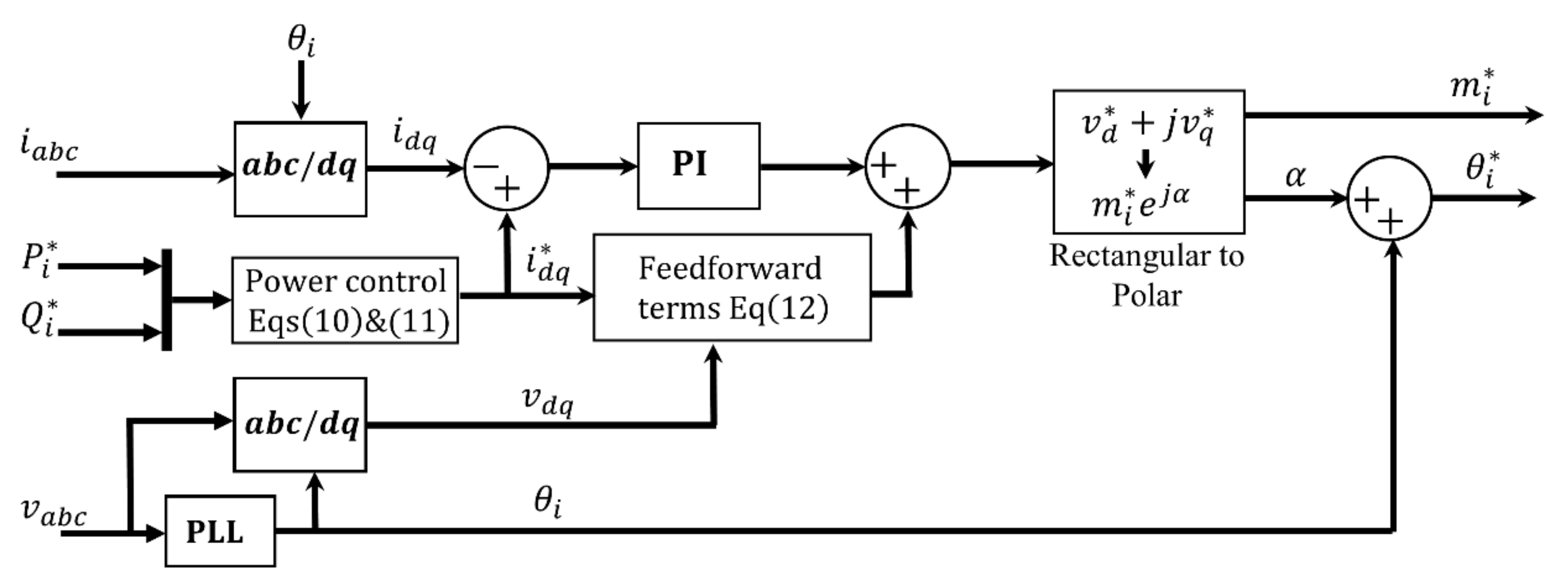
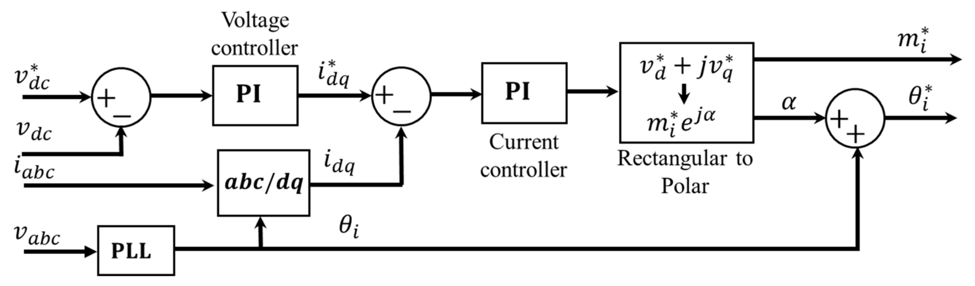
In order to realize the adopted converter in the AC microgrid a PWM strategy is proposed in this section adopting the concept of the nine switch and five-leg converter’s PWM [7,9] and [14,15], respectively. If the principle of the third-harmonic injection is employed, the reference voltage for the ith converter ( i = 1 ,   2 ,   3 ,   4 ) can be given as:
v i = 2 m i 3 [ s i n ( θ i ) + 1 6 s i n ( 3 θ i ) s i n ( θ i 2 π 3 ) + 1 6 s i n ( 3 θ i ) s i n ( θ i + 2 π 3 ) + 1 6 s i n ( 3 θ i ) ] + [ o s i o s i o s i ] ,
where, v i = [ v a i v b i v c i ] T , m i and θ i are the reference voltage, the modulated signal, and the electrical angular position of the load/source connected to the ith converter, respectively. The offset ( o s i ) is added to the reference voltage signals to avoid any intersection (overlapping) between the converters references. Adopting the concept of the nine switch converter the offsets can be given as: o s 1 = m 3 m t , o s 2 = m 4 m t , o s 3 = m 1 m t , and o s 4 = m 2 m t where, m t = i = 1 4 m i and due to utilization of third harmonic injection m t 1.15 .
Figure 3 illustrates the generalized PWM scheme that is employed to obtain the gate pulses for the AC/AC converter.
v a 1 * = v a 1 + v c 2 v b 1 * = v b 1 + v c 2 v a 2 * = v a 2 + v c 1 v b 2 * = v b 1 + v c 1 v c 1 * = v c 1 + v c 2 = v c 2 * v a 3 * = v a 3 + v c 4 v b 3 * = v b 3 + v c 4 v a 4 * = v a 4 + v c 3 v b 4 * = v b 4 + v c 3
v c 3 * = v c 3 + v c 4 = v c 4 *
where v i * = [ v a i * v b i * v c i * ] T are the modulated phase voltages adopting the concept of the five-leg converter.
The modulated voltages are compared to a triangular (carrier) to generate the gate pulses as shown in Figure 3. The gate pulses for the upper switches of the converter ( S 1 H S 5 H ) are ON, if the values of the voltages in (2) are larger than the carrier. Otherwise they are OFF. The gate pulses of the lower switches of the converter ( S 1 L S 5 L ) are ON if Equation (3) is less than the carrier. Otherwise they are OFF. The gate pulses of the middle switches of the converter ( S 1 M S 5 M ) are generated by XORing the status of the upper and lower switches adopting the concept of the nine-switch converter.

2.2. Control Method

In this subsection, the controllers needed to regulate the output active power, output reactive power and the dc link voltage as well as the speed of the PMSM are designed and discussed. As all four converts are working independently, the equivalent circuit of each converter can be represented by individual voltage source inverter (VSI) as in Figure 4.
From Figure 4, in the abc-reference frame, the phase voltage and current holds the following relation:
v a c o n = R i a + L d d t i a + v a v b c o n = R i b + L d d t i b + v b v c c o n = R i c + L d d t i c + v c ,
where, v a b c c o n = [ v a c o n v b c o n v c c o n ] T is the converter side phase voltage, v a b c = [ v a v b v c ] T is the source side phase voltage and i a b c = [ i a i b i c ] T is the phase current. R and L are the equivalent resistance and inductance, respectively. They can represent the transformer and/or filter resistance and inductance, respectively.
Transforming (4) to synchronously rotating reference frame, yields
[ v d c o n v q c o n ] = [ R + L s ω L ω L R + L s ] [ i d i q ] + [ v d v q ] ,
where ω is the angular power frequency of the system and s is the differentiation operator (d/dt). v d , v q , i q , and i d are the direct and quadrature axis voltages and currents, respectively.
In per unit, the instantaneous active and reactive power can be represented in dq-axis synchronously rotating reference frame as
P = v d i d + v q i q ,
Q = v d i q v q i d ,
the q -axis voltage component of the rotating reference frame will vanish (i.e., v q = 0 ), if the d -axis of the rotating reference frame is aligned to the AC voltage vector. Thus, the instantaneous power in d q - synchronously rotating reference frame can be simplified. Under this assumption, (6) and (7) can be rewritten as follows:
P = v d i d ,
Q = v d i q ,
to this end, the reference current can be directly calculated given the reference power, that is
i d * = P * v d ,
i q * = Q * v d ,
where ‘*’ indicates the reference value, i.e., P i * is the reference active power for the ith converter.
To regulate the current, a proportional integral (PI) current controller with feedforward term is used, that is
[ v d c o n v q c o n ] = [ v d P I ω L i q + v d v q P I + ω L i d + v q ] ,
substitute (12) into (5) and rearranging, the coupling terms between the i q and i d dynamics will be cancelled as a result of the feedforward term in (12), which yields
[ v d P I v q P I ] = [ R + L s 0 0 R + L s ] [ i d i q ] ,
where v P I = [ v d P I v q P I ] T is the output voltage vector of the PI current controller that can be written as:
[ v d P I v q P I ] = [ K d P + K d I s 0 0 K q P + K q I s ] [ e d e q ] ,
e = [ e d e q ] T = [ i d * i d i q * i q ] T   is the error vector between the reference current and the actual one.
One method to design the gains of the current controller is to assume that, the closed loop time constant of the current inner loop is τ c then by selecting K d q P = L τ c and K d q I = R τ c , the closed loop transfer function between the reference and actual current can be written as
i * i = 1 τ c s + 1 ,
Figure 5 shows the active and reactive power control of the RESs converters. It consists of a phase-locked loop (PLL) to measure the electrical angular position ( θ ) of the generated voltage of the RES, current reference generation given the reference power as in (10) and (11) and a PI current control (14) with feedforward terms as in (12). The reference modulated signal ( m i * ) and reference electrical angular position ( θ i * ) are obtained from the current controller output and θ as shown in Figure 5.
Figure 6 shows the dc link voltage control of the grid side converter, the dc link voltage is measured and compared to a reference value. A PI voltage controller is employed to generate the reference current which is regulated via an inner PI current controller, then m i * and θ i * for the gird side converter are obtained as shown in Figure 6.
For the electric-drive side converter, Figure 7 shows the speed control of the PMSM. The motor speed is measured and compared to a reference speed, then, a PI speed controller process the error signal to provide a q -axis current reference ( i q * ) to the inner PI current controller. The d -axis current is kept zero ( i d * = 0 ) to achieve maximum torque per ampere. A non-interacting controller is employed to decouple the d and q dynamics. The non-interacting controller is similar to the decoupling controller discussed in Section 2.2. Finally, m i * and θ i * are obtained as shown in Figure 7.
All the gains of the PI controllers used in Figure 5, Figure 6 and Figure 7 are optimized in the next section to minimize a weighted sum objective function.
The controllers select the suitable m i * and θ i * , then the references are formulated as in (1). Finally, the gate pulses of the converter are realized as in Figure 3, employing (2) and (3).

3. Optimal Tuning of Converter Controllers

To achieve satisfactory reference tracking and disturbance rejection with minimum dc voltage ripple while ensuring that the THD at PCC are less than 5%, to avoid harmonic related problems. The gains of the utilized controllers are optimized by minimizing a weighted sum of different objective functions. Each objective function represents a specific aspect to be minimized. For this purpose, the following weighted sum objective function (J) is formulated
J = β 1 t 0 t s ( v d c * v d c ) 2 d t + β 2 t s t f v d c ripple 2 d t + β 3 t 0 t f t ( ω m o t o r * ω m o t o r ) 2 d t ,
Subject to
K m i n K K m a x ,
  T H D i < 5 %
t 0 , t f , and t s are the simulation starting time, simulation termination time, and the time needed for the response to settle down within 2% from its final value, respectively.
The first term in (16) represents the transient behavior of the dc link voltage, the second term reflects the ripple in the dc link at steady state, while the last term in (16) represents a balance between reference tracking and disturbance rejection in the motor speed response measured by the integral of time multiply squared error (ITSE). β 1 , β 2 , and β 3 are weight of the priority of each objective function in the weighted sum objective function (16). Equation (17) represents the controllers gains lower ( K m i n ) and upper ( K m a x ) bounds, while (18) represents the harmonic constraints imposed to fulfill IEEE 1547 harmonic standards. The optimization problem in (16) subjected to constraints (17) and (18) is solved using PSO which is summarized in the flow chart shown in Figure 8.
PSO executes three main steps, while solving the optimization problem, repeatedly until termination policy has been met. These steps consist of evaluating the fitness of each particle, updating the personal and global best, and updating the position and velocity of each particle.
To optimal tune the controllers gains ( K ), the particle’s velocity and position are updated employing Equations (19) and (20), respectively [17,18,19].
  v i t + 1 = ω × v i t + c 1 × r 1 × ( P i t K i t ) + c 2 × r 2 × ( G t K i t )
  K i t + 1 = K i t + v i t + 1
where v is the velocity at which the gains are updated, i is the particle number, t is the iteration number. P i t is the particle best gains and G t is the global best gains at iteration t , respectively. c 1 , c 2 , and ω are the PSO parameters. c 1 and c 2 are positive acceleration constants utilized to scale the contribution of the cognitive and social components on the solution, respectively. ω is called the inertia coefficient, its value has impact on the solution convergence. Therefore, different methods of choosing the value of ω ranging from simple static to dynamically changing methods have been used in the literature. A review of ω , c 1 , and c 2 selection methods with their impact on the optimization solution can be found in [19]. Finally, 0 r 1 , r 2 1 are random numbers which introducing the stochastic nature to the search algorithm.
In this study, ω is chosen to have a linearly decreasing value obeying Equation (21)
ω = 0.9 0.5 × t / t m
where t m is the number of iterations. Adopting Equation (21), the inertia coefficient of the current velocity when finding the next velocity will decrease linearly favoring exploitation as the optimization progresses. Furthermore, c 1 and c 2 are assigned the values of 1.5 and 2, respectively. This selection pushes the particles more toward the global best position than its local solution which makes the solution progress towards the optima.
Moreover, the selection of the number of iterations and particles are problem dependent that have impact on the solution convergence. The number of iterations should be selected as a trade-off between complexity of the calculation and the accuracy of the solution. On the other hand, the search space that can be covered by the swarm has a direct relation with the number of particles in swarm. Nevertheless, large number of particles will increase the complexity of the optimization dramatically. From empirical point of view, it is recommended to select the number of particles between 10 and 30 to have a good balance between the complexity and convergence of the solution [19].
In this work, the number of iterations ( t m ) is selected to be 500 and the number of particles is 20.

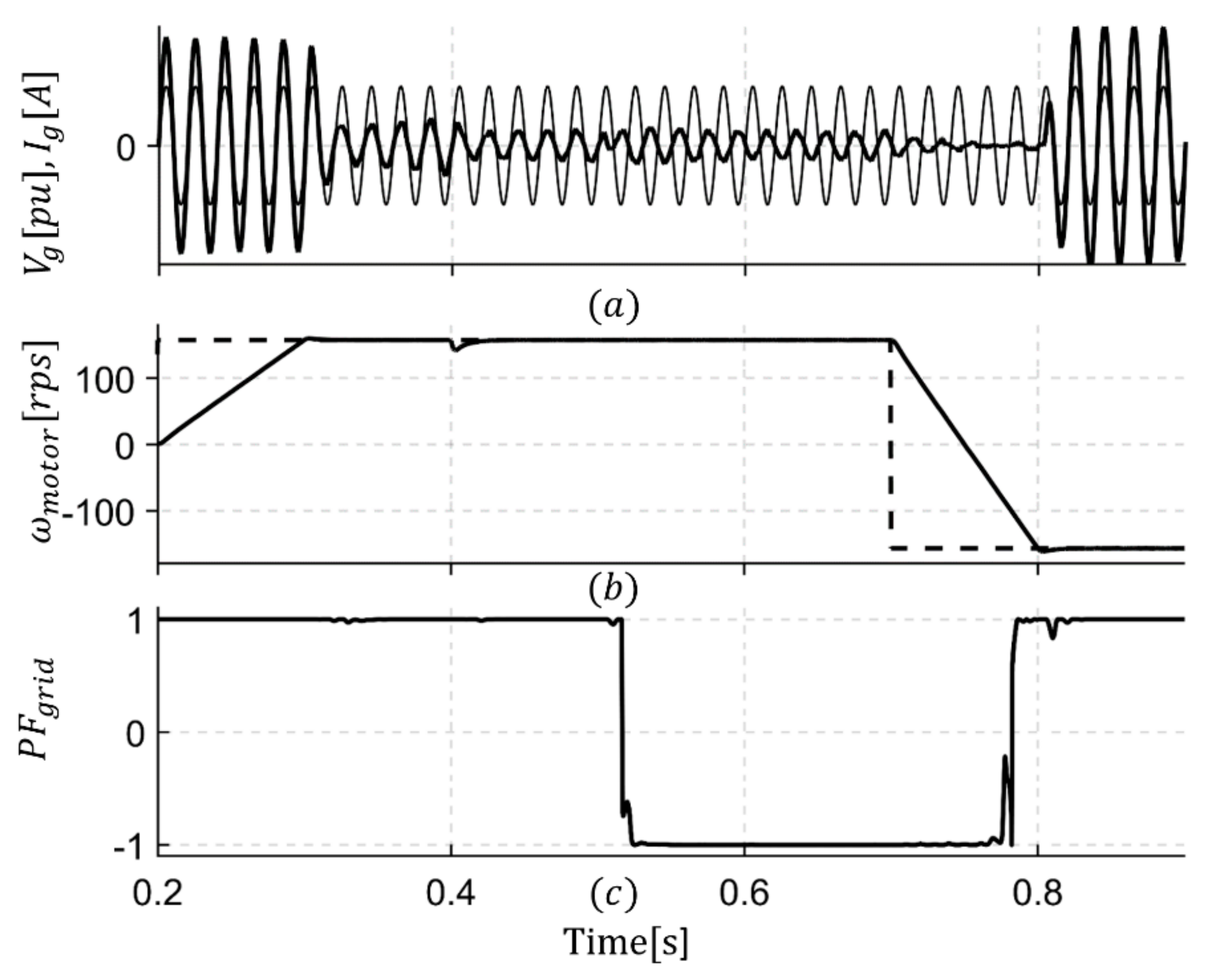
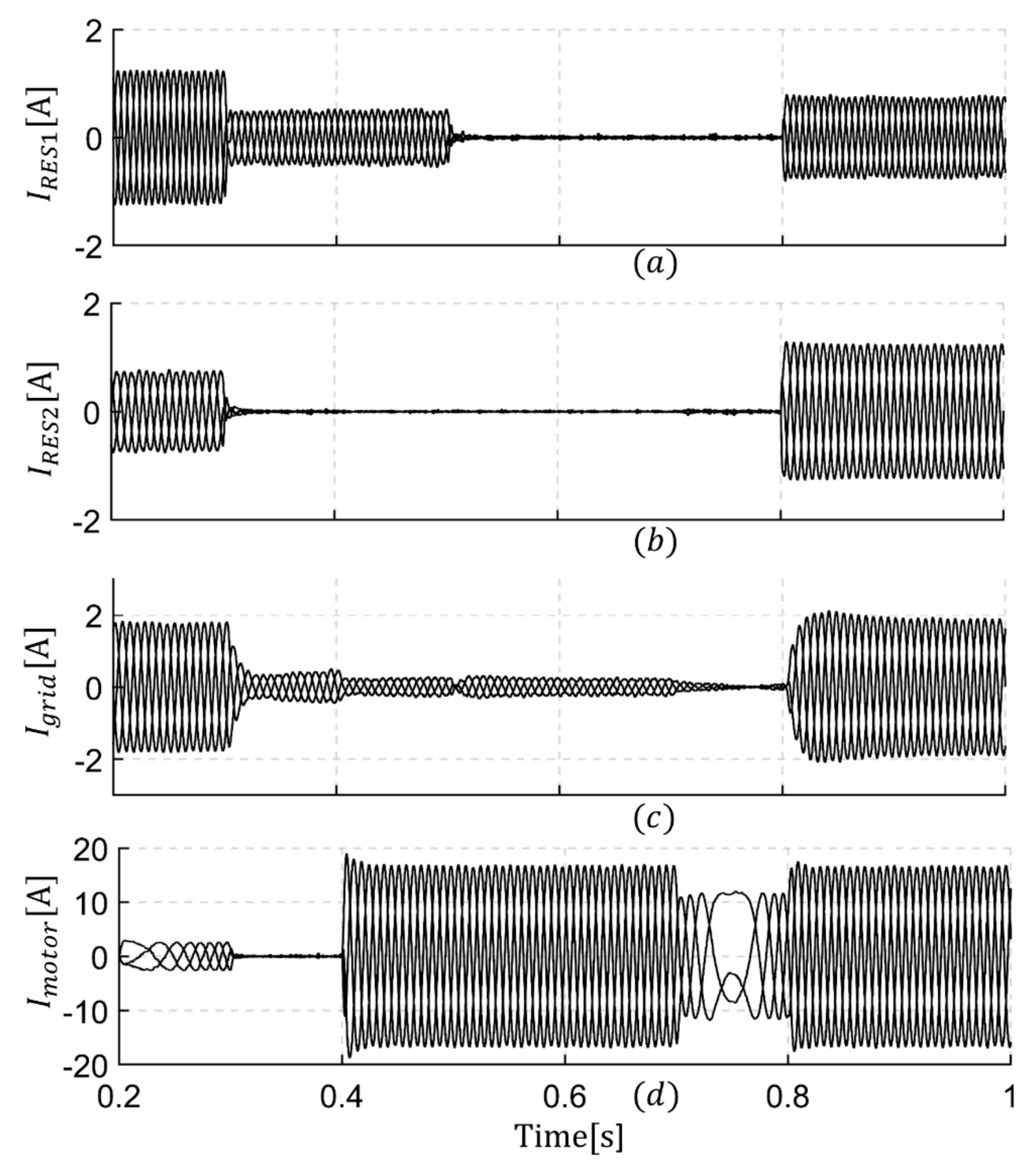
4. Results and Discussion

As shown in Figure 1, the RESs are connected to the AC/AC converter via Y/Δ transformers (5 kV/380 V). A choke ( L c h o k e = 1 mH) is connected between the PMSM and the drive side converter (converter 2). The switching frequency is 10 kHz and the dc link voltage reference is 1 kV, the dc link capacitor C = 300   μ F . The PMSM has R a = 0.86 Ω, L d = 8   mH, L q = 20   mH, flux linkage of the permanent magnet φ m = 0.12 wb, and number of pole pairs P = 2 . The fundamental power frequency of the RES1 is 60 Hz and it is 50 Hz for the RES2 while the grid frequency is assumed to be 50 Hz.
The gains of the employed PI controllers which are the outcome of the proposed optimization procedure are listed in Table 1 in which K P is the proportional gain while K I is the integral gain. Moreover, the parameters of the PSO are listed in Table 2.
The active power references for the RES1 (Converter 1) and RES2 (Converter 3) are −5 kW and −3 kW (Figure 9b,c), respectively. After 0.3 s, the active power reference of RES1 is changed to −2 kW (Figure 9b), while RES2 is out of service (Figure 9c). Then, at t = 0.5 s both RESs are out of service with zero active power reference. Finally, at t = 0.8 s both RESs are activated with power reference of −3 kW and −5 kW, respectively.
Such fast transient can represent and study power fluctuation in the microgrid and the reaction of the proposed system under such transients. The reactive power references for both RESs are kept zero all the time.
Figure 9a, shows the dc link voltage under fast transient while Figure 9d shows the power to the grid. As shown in Figure 10b the PMSM is activated and the motor tracks the reference speed within 0.1 s. Part of the generated power form the RESs is consumed by the motor and the remaining power is fed-back the grid. In this paper, positive power convention is adopted to represent the absorbed power. At t = 0.3 s. one of the RESs is out of service and the second one drop power to −2 kW. Therefore, the net power absorbed by the grid is reduced. The motor is loaded with T L = 6   N·m at t = 0.4 s. Good disturbance rejection can be seen in Figure 10b and less power to be fed to the grid (Figure 9d). Although, both RESs are out of service at t = 0.5 s, the grid took over the power flow and supplied the needed power to the motor with no effect on the motor speed (Figure 10b). At t = 0.7 s the motor speed is reversed, and the power taken from the grid is reduced due to regenerative braking mode of the PMSM. The RESs are back to active mode at t = 0.8 s and the grid absorbed the generated power from the RESs. During these fast transient, the dc link voltage shown in Figure 9a is regulated very fast (almost within 0.1 s) and with about 10% maximum deviation from its reference with low voltage ripple.
As a measure of the power flow direction in the microgrid, the power factor (PF) is shown in Figure 10c and the a-phase current and normalized phase voltage of the grid are shown in Figure 10a.
Figure 11, shows the three-phase current measured from the high side terminal of the used transformer for RES1 (Figure 11a), RES2 (Figure 11b), The grid (Figure 11c) and the PMSM (Figure 11d), respectively. Figure 12 shows the offsets needed to be added to the references in order to avoid overlapping between them.

5. Conclusions

This paper presented an optimal control of a mixed-grid-feeding-electric-drive system utilizing compact AC/AC converter in an AC microgrid. A PWM employing third harmonic injection and a control method are proposed to realize this mixed grid-feeding drive system. A procedure to optimize the gains of the controllers was presented, to achieve a satisfactory reference tracking and disturbance rejection with minimum dc voltage ripple while ensuring that the THD at PCC is less than 5%, to avoid harmonic related problems. Three objective functions are lumped together in weighted sum objective function. One of the objective function represented the transient behavior of the dc link voltage, the second reflected the steady state behaver of the dc link voltage, while the third objective function, provided a balance between reference tracking and disturbance rejection in the electric drive side converter measured by ITSE. Simulation results under fast transient are presented to highlight the capability of the adopted converter, PWM, and the proposed control method in the mix grid-feeding drive system. The applicability of the proposed system is not limited to industrial facilities hosting RESs but also may include, wind farm grid integration and electric vehicle drive systems.

Author Contributions

Investigation, I.A.S. and S.A.; Supervision, I.A.S.; Validation, I.A.S., S.A. and M.A.A.; Writing—original draft, I.A.S.; Writing—review and editing, I.A.S., S.A. and M.A.A.

Funding

Partial of the APC was funded by the deanship of research at Jordan University of Science and Technology.

Acknowledgments

Partial of the open access fees is supported by the deanship of research at Jordan University of Science and Technology.

Conflicts of Interest

The authors declare no conflict of interest.

References

  1. Smadi, I.; Albatran, S.; Ahmad, H. On the Performance Optimization of Two-Level Three-Phase Grid-Feeding Voltage-Source Inverters. Energies 2018, 11, 400. [Google Scholar] [CrossRef]
  2. Netsanet, S.; Zhang, J.; Zheng, D. Bagged Decision Trees Based Scheme of Microgrid Protection Using Windowed Fast Fourier and Wavelet Transforms. Electronics 2018, 7, 61. [Google Scholar] [CrossRef]
  3. Nejabatkhah, F.; Li, Y. Overview of Power Management Strategies of Hybrid AC/DC Microgrid. IEEE Trans. Power Electron. 2015, 30, 7072–7089. [Google Scholar] [CrossRef]
  4. Malik, S.; Ai, X.; Sun, Y.; Zhengqi, C.; Shupeng, Z. Voltage and frequency control strategies of hybrid AC/DC microgrid: A review. IET Gener. Transm. Distrib. 2017, 11, 303–313. [Google Scholar] [CrossRef]
  5. Rauf, A.; Sant, A.; Khadkikar, V.; Zeineldin, H. A Novel Ten-Switch Topology for Unified Power Quality Conditioner. IEEE Trans. Power Electron. 2016, 31, 6937–6946. [Google Scholar] [CrossRef]
  6. Qin, Z.; Loh, P.; Blaabjerg, F. Power loss benchmark of nine-switch converters in three-phase online-UPS application. In Proceedings of the 2014 IEEE Energy Conversion Congress and Exposition (ECCE), Pittsburgh, PA, USA, 14–18 September 2014. [Google Scholar]
  7. Jones, M.; Levi, E.; Wright, P.; Vukosavic, S.; Dujic, D. Five-leg inverter PWM technique for reduced switch count two-motor constant power applications. IET Electr. Power Appl. 2008, 2, 275–287. [Google Scholar] [CrossRef]
  8. Zhang, L.; Loh, P.; Gao, F. An Integrated Nine-Switch Power Conditioner for Power Quality Enhancement and Voltage Sag Mitigation. IEEE Trans. Power Electron. 2012, 27, 1177–1190. [Google Scholar] [CrossRef]
  9. Diab, M.; Elserougi, A.; Abdel-Khalik, A.; Massoud, A.; Ahmed, S. A Nine-Switch-Converter-Based Integrated Motor Drive and Battery Charger System for EVs Using Symmetrical Six-Phase Machines. IEEE Trans. Ind. Electron. 2016, 63, 5326–5335. [Google Scholar] [CrossRef]
  10. Ajami, A.; Alizadeh, R.; Elmi, M. Design and control of a grid tied 6-switch converter for two independent low power wind energy resources based on PMSGs with MPPT capability. Renew. Energy 2016, 87, 532–543. [Google Scholar] [CrossRef]
  11. Albatran, S.; Smadi, I.; Alsyouf, M. Experimental Validation of Shared Inverter Topology to Drive Multi AC-Loads. Int. J. Electr. Comput. Eng. 2018, 8, 793. [Google Scholar] [CrossRef]
  12. Dabour, S.; Rashad, E.; Abdel-khalik, A.; Ahmed, S.; Massoud, A. A new fifteen-switch inverter topology for two five-phase motors drive. In Proceedings of the 2016 Eighteenth International Middle East Power Systems Conference (MEPCON), Cairo, Egypt, 27–29 December 2016. [Google Scholar]
  13. Smadi, I.; Albatran, S.; Alsyouf, M. A novel compact AC/AC converter for hybrid microgrids. In Proceedings of the 2017 IEEE 6th International Conference on Renewable Energy Research and Applications (ICRERA), San Diego, CA, USA, 5–8 November 2017. [Google Scholar]
  14. Kominami, T.; Fujimoto, Y. A Novel Nine-Switch Inverter for Independent Control of Two Three-Phase Loads. In Proceedings of the 2007 IEEE Industry Applications Annual Meeting, New Orleans, LA, USA, 23–27 September 2007. [Google Scholar]
  15. Kominami, T.; Fujimoto, Y. Inverter with Reduced Switching-Device Count for Independent AC Motor Control. In Proceedings of the IECON 2007—33rd Annual Conference of the IEEE Industrial Electronics Society, Taipei, Taiwan, 5–8 November 2007. [Google Scholar]
  16. Delarue, P.; Bouscayrol, A.; Francois, B. Control implementation of a five-leg voltage-source-inverter supplying two three-phase induction machines. In Proceedings of the IEEE International Electric Machines and Drives Conference, Madison, WI, USA, 1–4 June 2003. [Google Scholar]
  17. Del Valle, Y.; Venayagamoorthy, G.; Mohagheghi, S.; Hernandez, J.; Harley, R. Particle Swarm Optimization: Basic Concepts, Variants and Applications in Power Systems. IEEE Trans. Evol. Comput. 2008, 12, 171–195. [Google Scholar] [CrossRef]
  18. Parsopoulos, K.E.; Vrahatis, M.N. Particle Swarm Optimization and Intelligence: Advances and Applications; Information Science Reference; IGI Global: Hershey, PA, USA, 2010. [Google Scholar]
  19. Engelbrecht, A. Computational Intelligence; John Wiley & Sons: Chichester, UK, 2008; Chapter 16. [Google Scholar]
Figure 1. AC microgrid employing the compact converter.
Electronics 07 00102 g001
Figure 2. Detailed power circuit for the employed AC/AC converter in Figure 1.
Electronics 07 00102 g002
Figure 3. Generalized PWM scheme.
Electronics 07 00102 g003
Figure 4. The ith converter equivalent circuit.
Electronics 07 00102 g004
Figure 5. Active and reactive power control of RESi side converter.
Electronics 07 00102 g005
Figure 6. DC-link voltage control for the grid side converter.
Electronics 07 00102 g006
Figure 7. Speed control of PMSM drive side converter.
Electronics 07 00102 g007
Figure 8. Flow chart of the proposed tuning procedure adopting PSO.
Electronics 07 00102 g008
Figure 9. The response of the (a) DC link voltage, active powers for (b) RES1, (c) RES2, and (d) grid-side.
Electronics 07 00102 g009
Figure 10. Response of the (a) grid current and normalized grid phase voltage, (b) PMSM speed, and (c) grid power factor.
Electronics 07 00102 g010
Figure 11. The responses of the (a) RES1 current, (b) RES2 current, (c) grid current, and (d) PMSM current.
Electronics 07 00102 g011
Figure 12. The needed offsets to be added to the reference voltages (a) offset for RES1 side converter, (b) offset for RES2 side converter, (c) offset for grid side converter and (d) offset for the drive side converter.
Electronics 07 00102 g012
Table 1. Optimization outcome.
Converter SideControllerParametersValues
DriveMotor Speed K p s 1.1
K I s 100.45
Motor d -axis Current K p I d m 11.98
K I I d m 1297.27
Motor q -axis Current K p I q m 29.96
K I I q m 1297.27
Griddc Voltage K p I d c g 8.09
K I I d c g 195.2
d q -axis Current K p I d q g 0.91
K I I d q g 59.86
RES d q -axis Current K p I d q R E S 0.91
K I I d q R E S 59.86
Table 2. PSO parameters.
ParametersValues
Swarm size20
Inertia coefficient ( ω )According to Equation (21)
Cognitive factor ( c 1 )1.5
Social factor ( c 2 )2
Number of iterations ( t m )500

