Article

Improving the Propagation Environment by Using Tunable Passive Repeater

Graduate school of Engineering, Iwate University, Ueda 4-chome 2-5, Morioka-shi, Iwate 020-8551, Japan
*
Author to whom correspondence should be addressed.
Electronics 2018, 7(2), 12; https://doi.org/10.3390/electronics7020012
Submission received: 15 November 2017 / Revised: 8 January 2018 / Accepted: 9 January 2018 / Published: 25 January 2018
(This article belongs to the Special Issue Smart Antennas and MIMO Communications)

Abstract

:
This paper presents a novel passive repeater that achieves enhanced Multiple-Input-Multiple-Output (MIMO) communication between two isolated terminals. The novel aspect of this work is an avoidance of the key-hole effect, which is normally caused by a repeater since all of the signal goes through the same point. Moreover, our idea uses electrical control, which is simply realized by only varactor diodes on the antennas, and this idea provides fast and low-cost control of the MIMO channel. This configuration allows the passive repeater to control the MIMO channel. MIMO channel capacity is maximized by controlling all repeater elements individually. The effectiveness of the passive repeater in enhancing MIMO channel capacity is verified by experiments. First of all, we obtained propagation data from field experiment, and propagation characteristics were evaluated using equations. The results show that the 10% value of MIMO channel capacity can be improved by 2.92 bits/s/Hz in an indoor propagation environment, which well confirms the effectiveness of the proposed method.

1. Introduction

Multiple-Input-Multiple-Output (MIMO) systems, which use multiple antennas at both the transmitter and receiver sides, offers high data-transmission rates even if the frequency band is limited [1]. However, actual transmission performance strongly depends on the propagation environment. There are two important factors that determine the channel capacity. One is the signal-to-noise ratio (SNR), and the other is spatial correlation [2]. Especially when the number of propagation paths is limited, MIMO channel capacity is decreased by the keyhole effect [3,4]. To overcome this problem, cooperative diversity using relay nodes was proposed. Cooperative diversity offers spatially multiplexed transmission and diversity transmission even when the source and destination terminals cannot directly communicate with each other. There are two major relay methods; amplify-and-forward (AF) and decode-and-forward (DF) [5,6,7]. AF amplifies the received signal, and relays the amplified signal to the receiver. AF is simple as signal processing is not performed by the relay station. However, its disadvantage is that noise is also amplified with the signal. DF, on the other hand, decodes the received signal, and retransmits the encode to the receiver. This method enhances the signal-to-noise ratio (SNR) since the noise is suppressed during the decoding process. However, DF wastes temporal or spectral resources since the receiving and transmitting signals cannot use the same channel simultaneously. Note that both AF and DF consume electric power to operate. In order to resolve these problems, the passive repeater, which can re-radiate a received signal in a specific direction, has been proposed for MIMO communication [8]. The passive repeater can control path direction to improve channel capacity without noise-amplification, signal-processing, or power-consumption. Receiving power is improved when the signal is relayed by a passive repeater, which is demonstrated in [9]. However, that work assumed that the position of the receiving antenna was fixed. Providing the passive repeater with the ability to steer the relayed signal is very attractive since it supports arbitrary locations of the source and destination terminals. Another approach is the phase-controlled relay scheme proposed in [10]. In this method, the relay station has as many phase shifters as there are relay antennas and the phase of the relayed signal can be controlled. An improvement in channel capacity was numerically validated. However, no configuration of a feasible repeater antenna was presented. Also, the study assumed that the number of relay-node antennas equaled the number of transmitter/receiver antennas.
To decrease the keyhole effect, far more relay antennas than transmitting/receiving antennas were needed [3,4]. Basically, the keyhole effect decreases channel capacity as it reduces the number of eigenvalues. Our solution is a passive relay scheme that uses a tunable transmit-array antenna that has a lot more antenna elements than the transmitting/receiving antennas. Antennas with tunable reactance devices are used to improve the MIMO channel characteristics in environments experiencing the keyhole effect. The effectiveness of the tunable transmit-array has been numerically and experimentally verified [11,12,13]. The propagation characteristic can be controlled by tuning the transmit array installed in wall aperture. By changing the load-reactance values of the dipole elements, the transmit array offers highly effective propagation channel control. However, this technique cannot be applied to situations where the source and destination stations are mutually hidden by walls.
This paper proposes a tunable passive repeater consisting of microstrip antennas and varactor diodes; its performance is evaluated experimentally. The work of [14] assumes that phase rotation is performed by mechanically rotating a table. The proposed tunable repeater uses only simple electric switches to control phase, which is a great advantage over existing work. In contrast to the authors’ previous works [11,12,13], this passive repeater offers MIMO transmission even across walls that completely separate the terminals. This means all signals must pass through the same point, the passive repeater. The most important feature in this scheme is its tunability. Although all paths pass through the same point, which would normaly trigger the keyhole effect, the tunable microstrip antennas perturb the path direction and spatial correlation is lowered. Furthermore, it can deliver the signals to any terminal location in the adjoining room. Another feature is that this passive repeater has very low power consumption since it has neither transmitters nor receivers. Also, it does not yield additional noise at the repeater since it does not have any amplifiers. It works bi-directionally since all components are passive. Since the re-radiated power of the passive repeater is low, it needs a lot of antennas to establish many propagation paths. This configuration is expected to fully utilize the re-radiation power available. The authors used simulations and an experiment to evaluate the improvement in channel capacity [15]. This paper introduces more detailed data focusing on actual measurments. Novel points of this paper are summarized below:
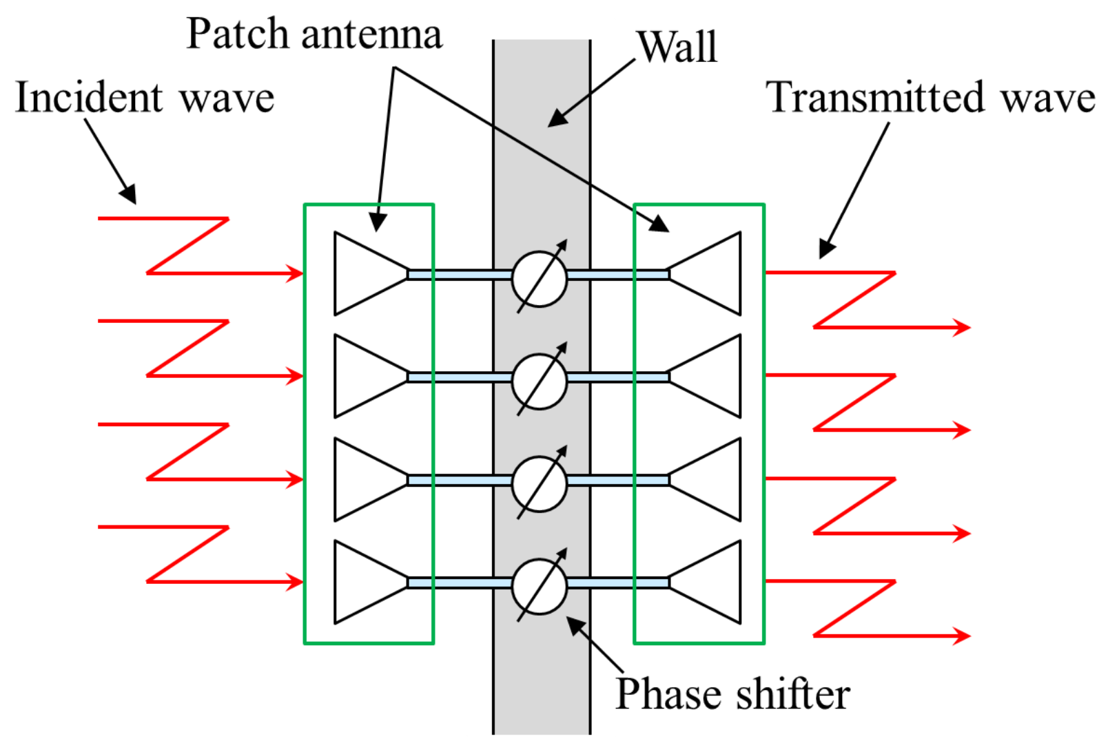
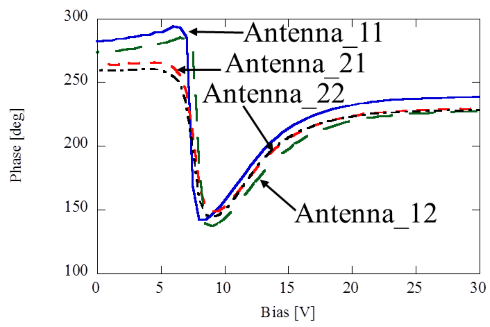
  • The phase of each relayed signal is individually controlled by simply mounting diodes on the relay antennas.
  • Spatial multiplexing efficiency is enhanced as the proposed tunable passive repeater offers control of the MIMO channel.
  • The effectiveness of the tunable passive repeater is verified by a field experiment.
Section 2 introduces the concept of the proposed passive repeater and the experimental environment. Section 3 describes the experimental evaluation method and results to demonstrate the validity of tunable passive repeater.

2. Passive Repeater Concept and Its Configuration

2.1. What Characteristics Are Best for the Tunable Passive Repeater?

This work assumes the following requirements for the passive repeater’s performance:
  • Good relay performance is available regardless of receiving antenna location.
  • No keyhole effect occurs due relay.
The following simulation demonstrates that these 2 requirements are satisfied by our tunable passive repeater. The channel matrix between transmitter and receiver (includeing phase shifter) is expressed as
H = H 2 θ H 1
θ = diag θ 1 , , θ K
where θ i is the phase shift at the i-th antenna element at the repeater. H 1 , H 2 represent the i.i.d channel and values of H 1 and H 2 matrices are fixed. SNR is set to 20 dB. The numbers of transmitter/repeater/receiver antennas are 2/16/2, respectively. θ is a random variable number, and 1000 trials are conducted. Figure 1 plots the cumulative distribution function (CDF) of channel capacity with the phase variable function active. This result shows that channel capacity is altered by the repeater, because eigenvalues increase with the phase of the re-radiate beam being aligned. That is, channel capacity is mostly determined by θ . Figure 1 indicates that if the phase of the passive repeater is optimized, high quality propagation is available regardless of receiver location. Figure 2 plots the CDF of channel capacity with the phase variable function active. This result implies that optimizing the phase values reduces the spatial correlation.

2.2. Concept of Proposed Method

Figure 3 shows the basic mechanism of our tunable passive repeater. There are two spaces separated by a solid wall that blocks all signals. The two array antennas of the relay are connected by coaxial cables that pass through the wall. Between their reception and re-transmission, the phases of the signals are altered by the phase shifters. Since the passive repeater uses array antennas, this is equivalent to controlling the propagation direction. Therefore, it is expected that the tunable passive repeater can improve SNR and decrease the spatial correlation coefficient.

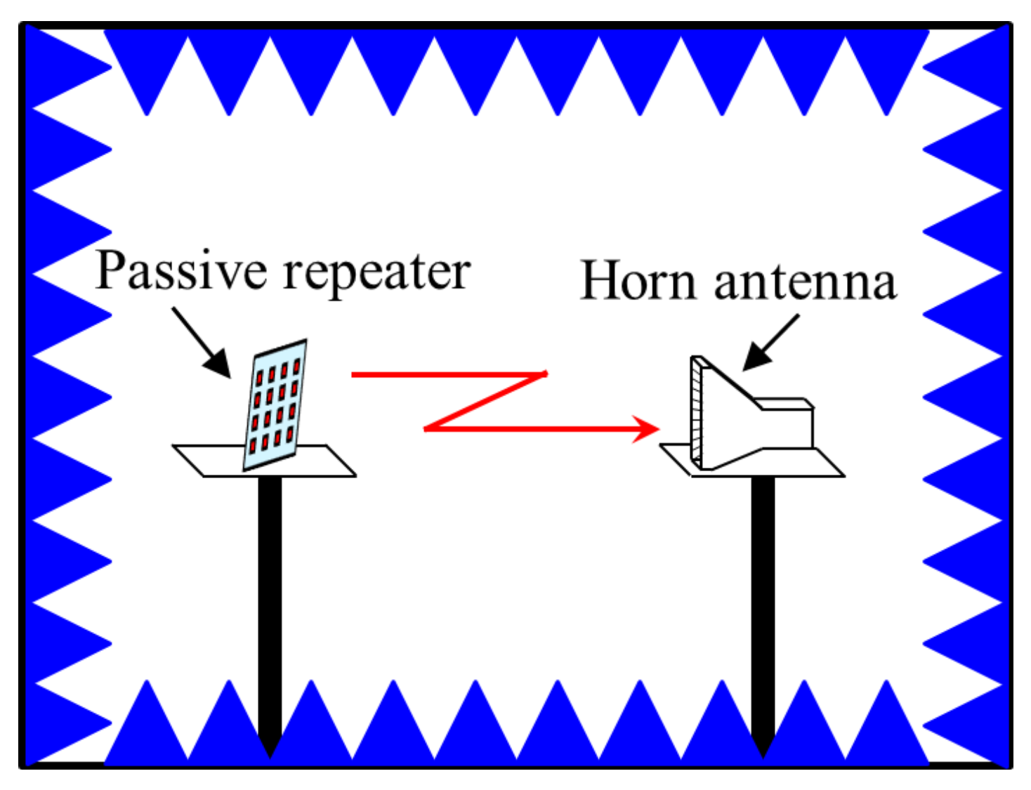
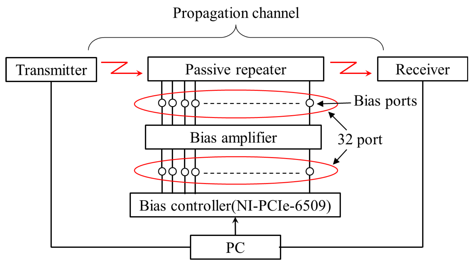
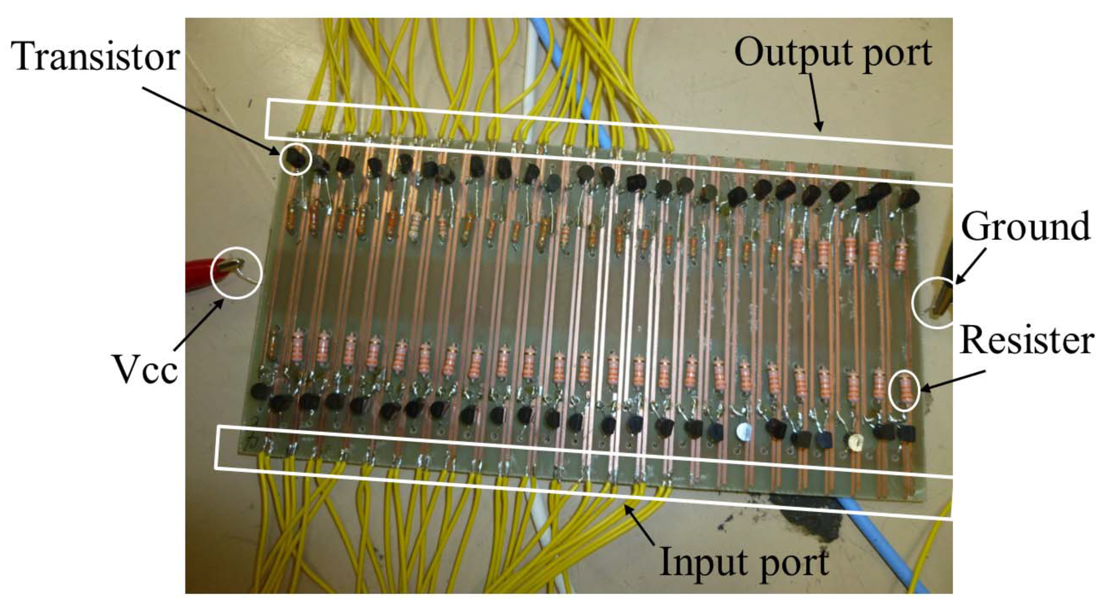
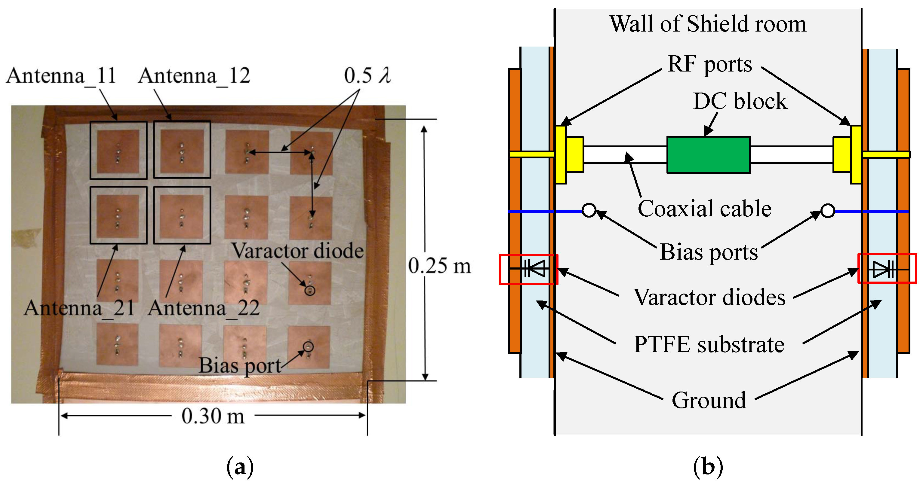
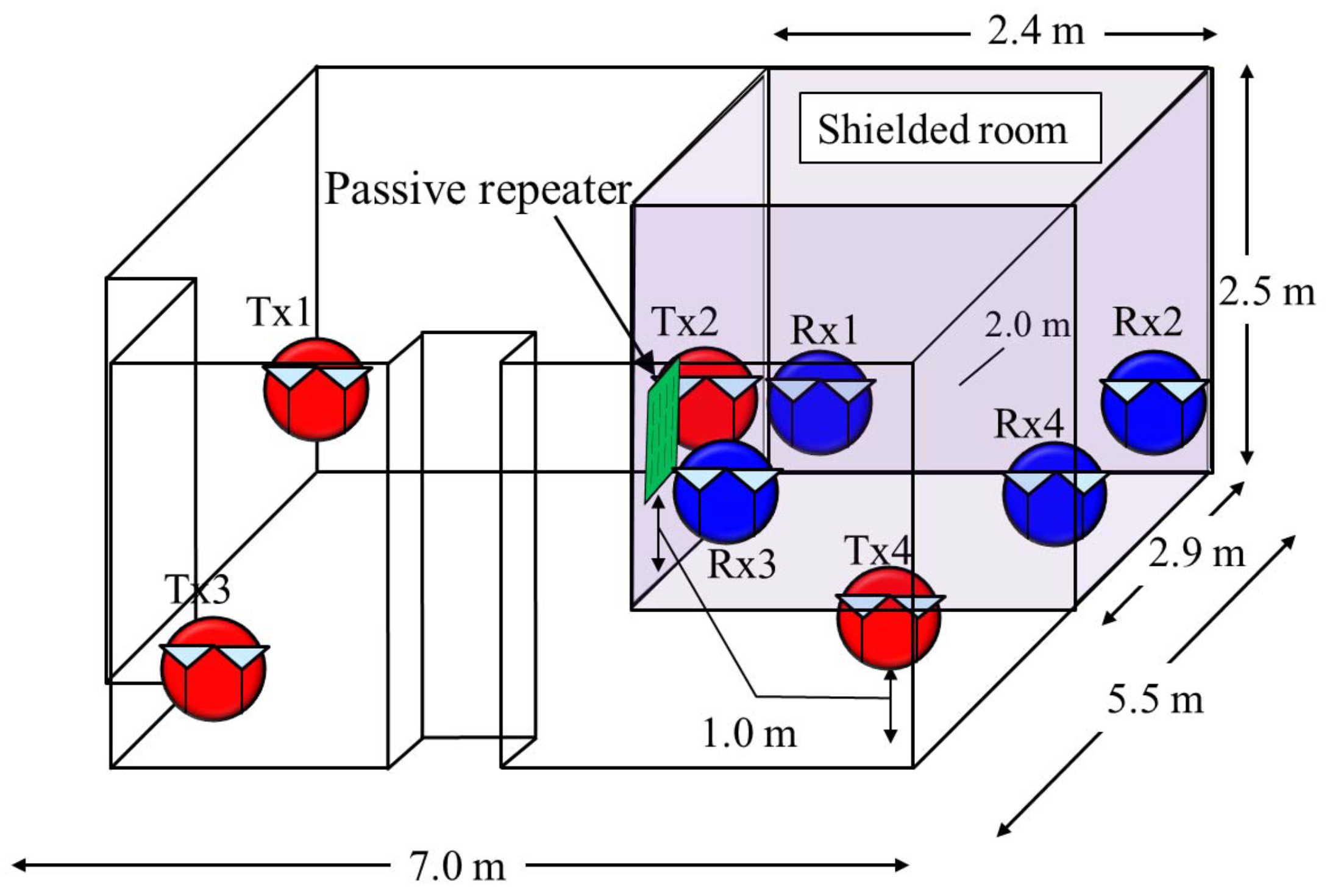
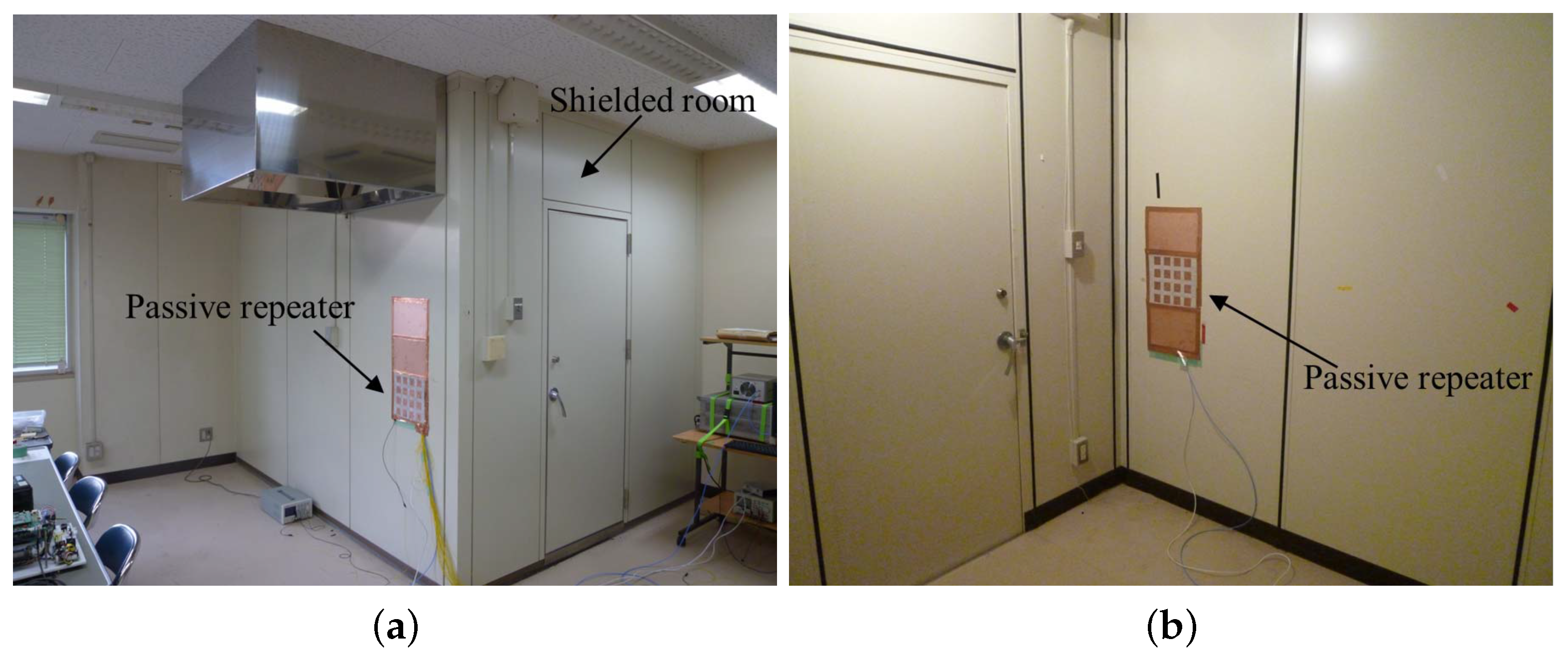
2.3. Fabricated Tunable Passive Repeater and Measurement Condition

Figure 4a shows a photo of a fabricated tunable passive repeater. It consists of rectangular patch antennas printed on a polytetrafluoroethylene (PTFE) substrate. The substrate’s relative permittivity and loss tangent are ε r = 2.237 and tan δ = 0.0008 , respectively. The substrate is 250 × 300 mm 2 , 1.60 mm thick. The backside of the substrate is fully covered by the ground conductor. Inter-element spacing of the patch antennas is set to 0.5 λ ( λ : wavelength in vacuum). The number of elements is 4 × 4 = 16 . The circles on the passive repeater in Figure 4a indicate bias port and varactor diode (HVU316: Renesas Technology). Figure 4b shows a cross-section of the proposed configuration to explain the structure. The passive repeater is a back to back array antenna as shown in Figure 4a; its RF ports are connected by coaxial cables. Changing the DC bias voltage shifts the output signal phase, since the DC bias controls the reactance value of the varactor diodes attached to the patch antennas, and this changes the resonance frequency. As shown in Figure 4b, each patch antenna is loaded with a varactor diode and has an independent bias port. The bias port is placed at the center of the patch antenna, so no RF signal flows in. Moreover, inserting a DC block into the coaxial feeder cable permits each patch antenna to be controlled independently. In this way, the phase of the signal incident on each patch can be independently controlled; this offers high flexibility in altering channel characteristics since the number of the combinations of the relayed phase is quite great.
As mentioned above, as the antenna elements also function as phase shifters, the proposal offers low power consumption [16]. While this is a simple configuration, the phase shift characteristics differ from those of an ideal phase shifter. Therefore, the phase-shift characteristics of the as-built passive repeater need to be determined. Also, appropriate bias values must be chosen since the digital I/O board outputs.
Figure 5 shows the anechoic chamber used to experimentally evaluate the transmission properties of a fabricated passive repeater. This experiment used just one half of the passive repeater as transmitter. Bias voltage was applied to one patch antenna of the passive repeater; the other antennas were terminated by 50 Ω impedances. A horn antenna was used as receiver. The bias voltage applied to the varactor diode was varied from 0∼30 V and the transmission characteristics of amplitude and phase were obtained.
Figure 6 plots the relationship between amplitude and bias voltage. Figure 7 shows the relationship between phase and bias voltage. These data can be obtained when the horn antenna receives the signal from passive repeater. Curves Antenna11∼Antenna22, correspond to the antennas shown in Figure 4a.
From Figure 6, it can be seen that amplitude varies greatly with the change in bias voltage. This result means that the value of the varactor diode impacts the impedance matching of the patch antenna. Considering this, for impedance matching the bias voltage applied to varactor diode must exceed 11 V. Also, from Figure 7, it can be seen that the phase variation indicates that the usable bias voltage range is 6∼25 V. A consideration of the amplitude and rotational phase characteristics indicates the bias voltage combination should be 11 V and 25 V, respectively. This paper compares the propagation characteristics yielded by 0 V, 11 V, and “optimum”. 0 V indicates no matching voltage, 11 V indicates matching voltage, and “optimum” indicates the optimized combination of phase achieved by 11 V and 25 V.

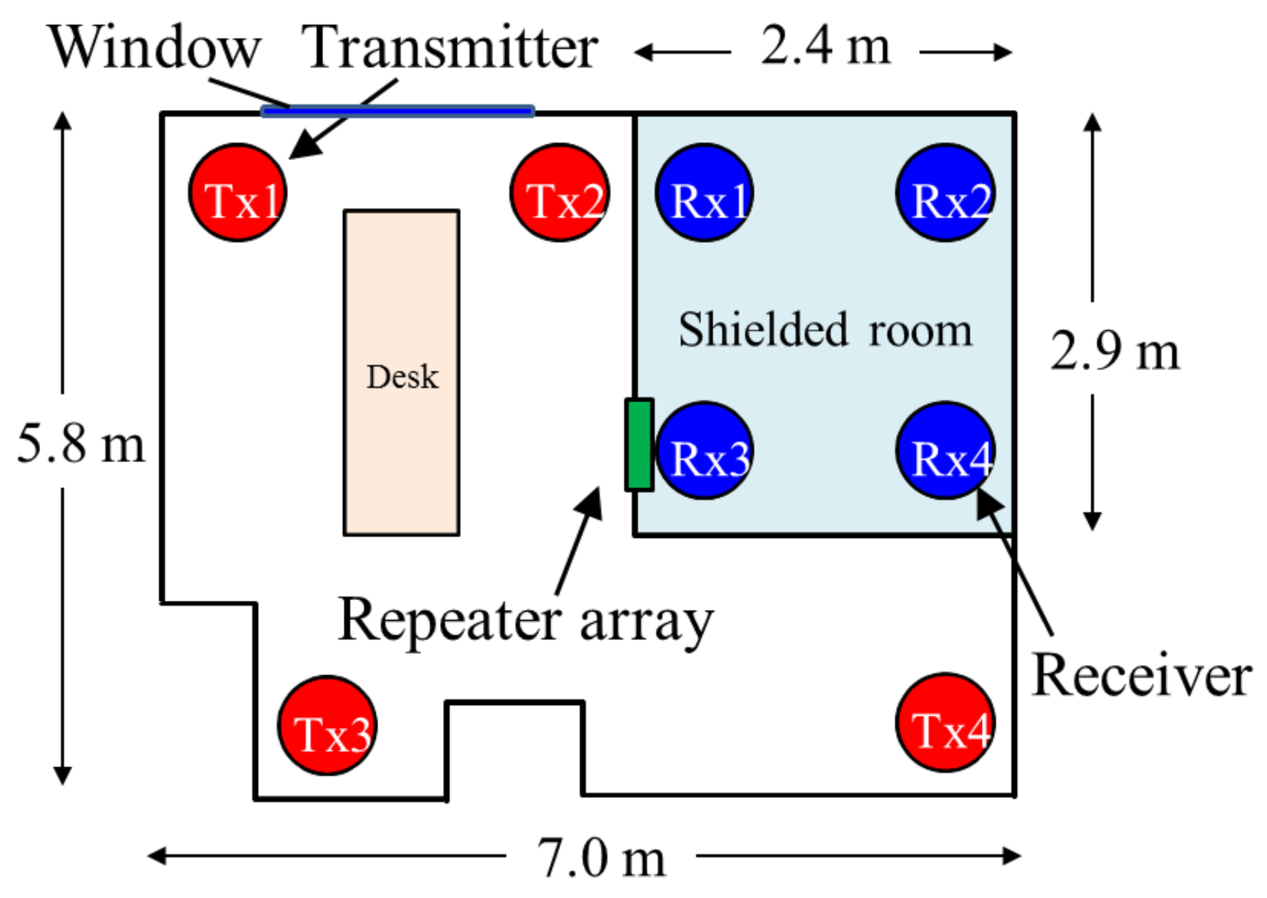
2.4. Measurement Condition
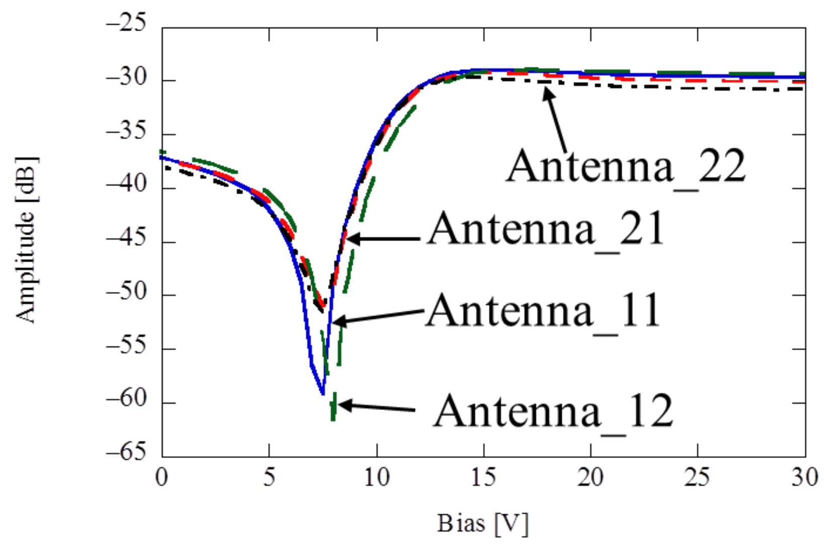
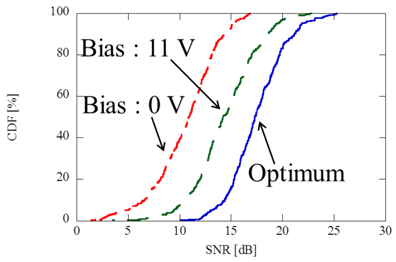
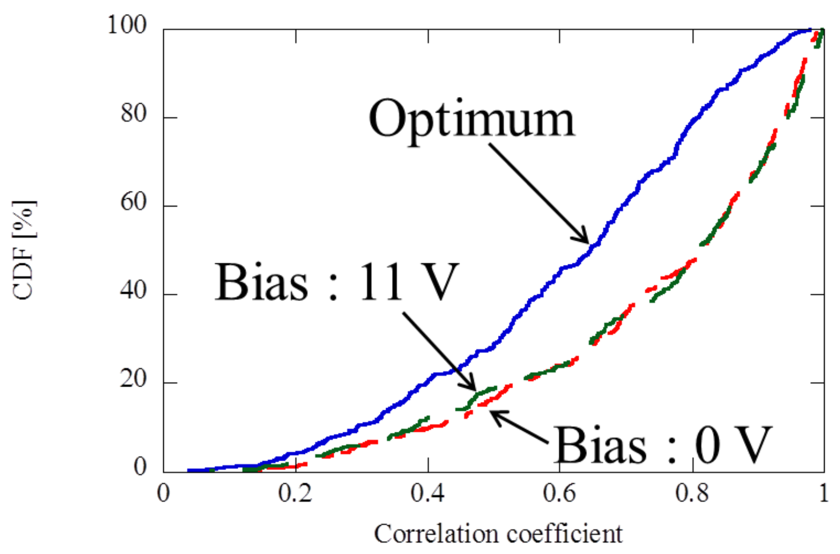
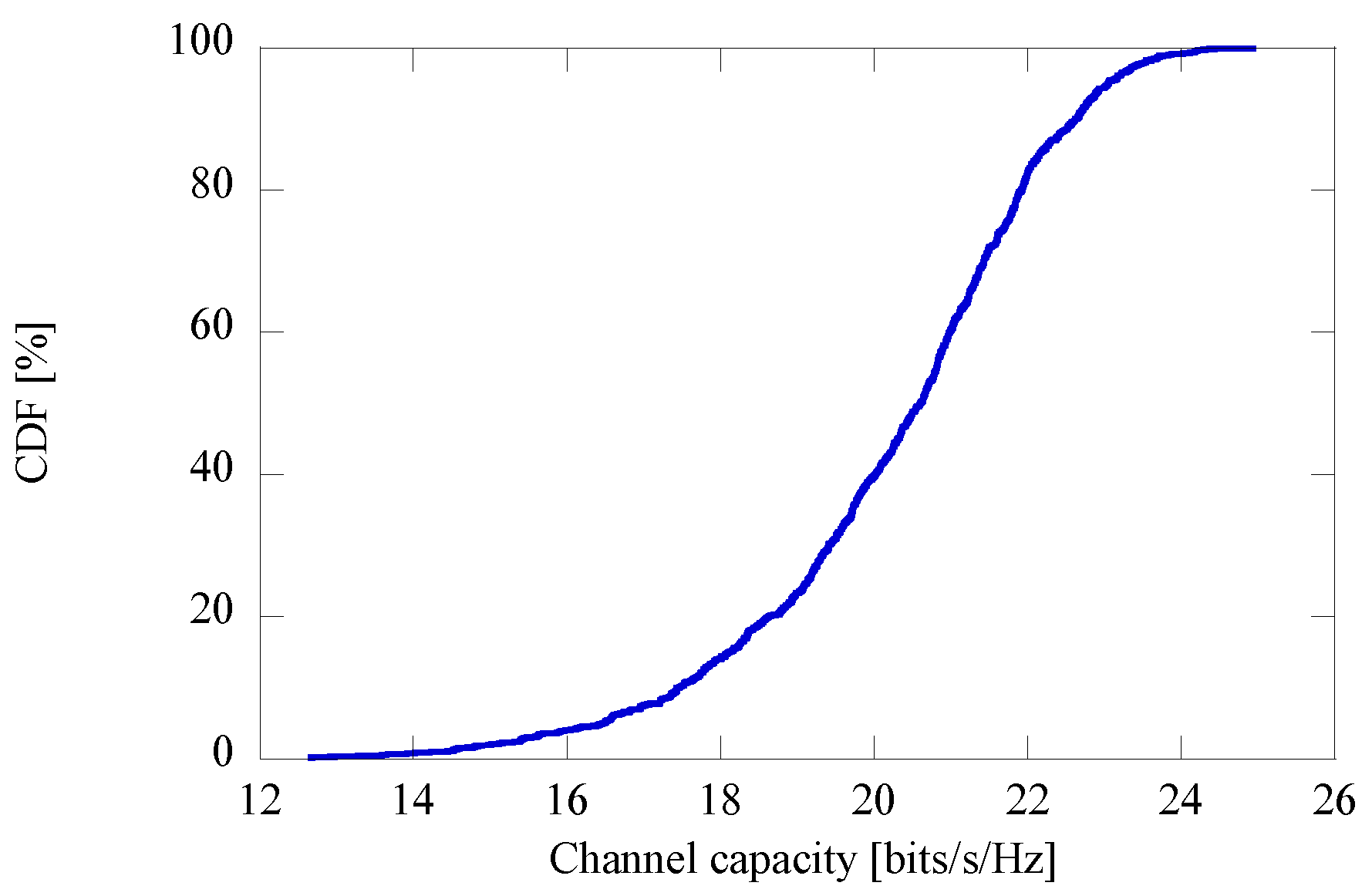
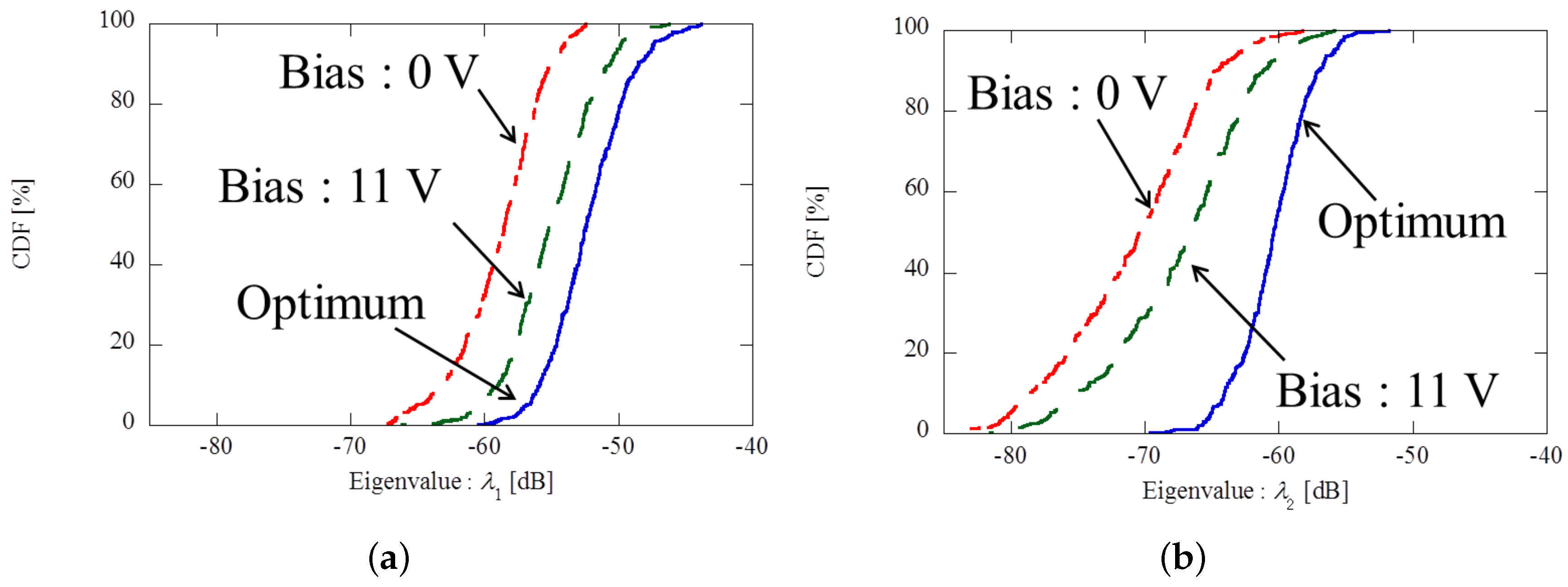
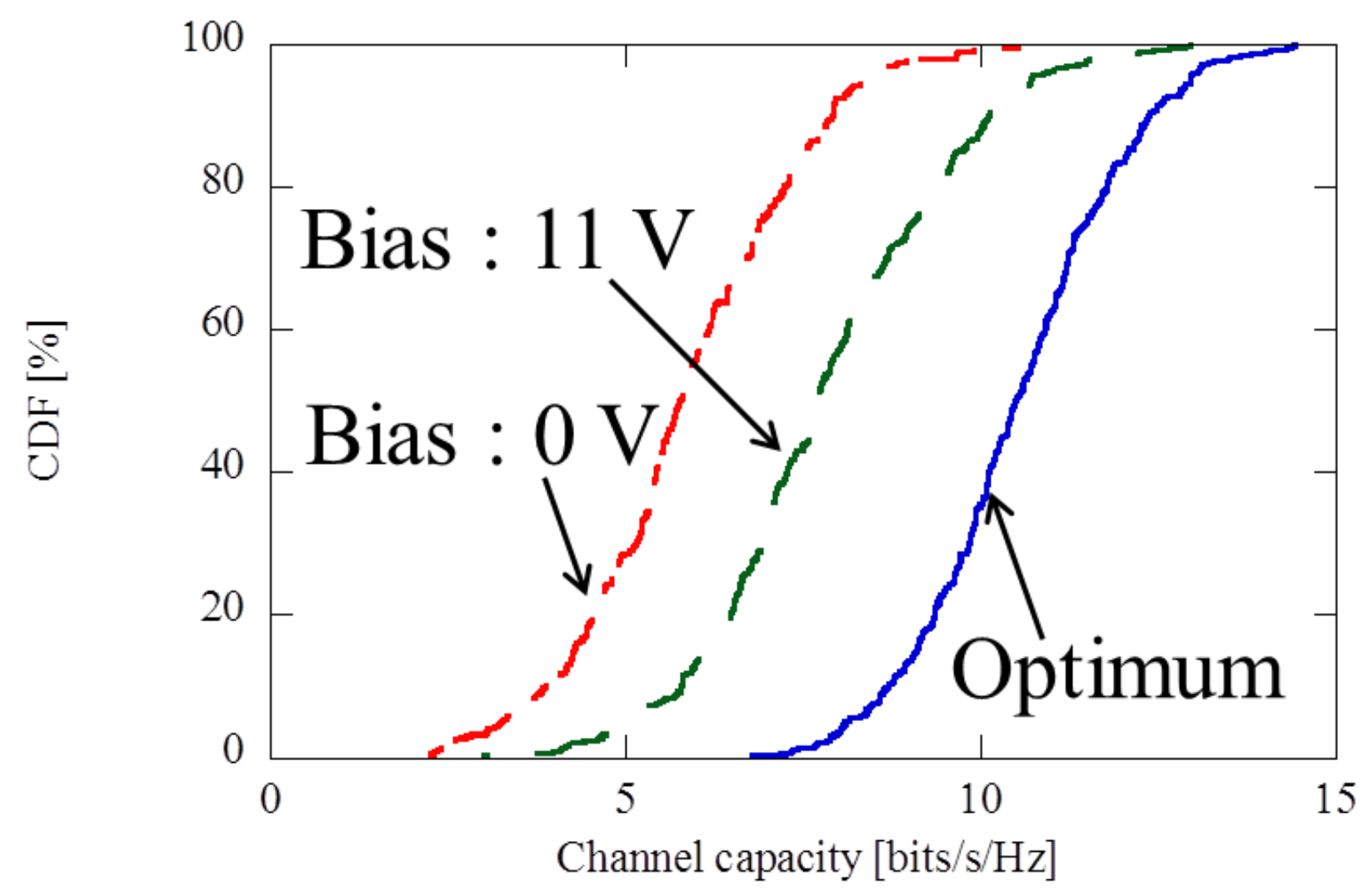
Figure 8 shows the experimental system used in this study. The propagation channel between transmitter and receiver, which is controlled by the passive repeater, was acquired by a PC. NI-PCIe-6509 (96-channel digital I/O board, National Instruments) was used as the multiple bias-voltage controlling unit. The output voltage of NI PCIe-6509 is 0 V or 5 V, and this is too low to control the varactor diodes since the voltage range required is 11∼25 V. In order to obtain sufficiently high voltages, a bias amplifier was used. Figure 9 shows a photo of the bias signal amplifying circuit consisting of transistors (2SC1815-Y) and 33 K Ω resistors. This circuit converts the input voltages of 0 and 5 volts to the desirable output voltages of 11 and 25 volts.
Figure 10 shows a top view of the experimental environment. Figure 11 shows an elevation view of experiment room. The size of the room was 7.0 × 5.8 × 2.7 m 3 . Wall material was concrete. This room has windows and a shielded room. The shielded room, 2.4 × 2.9 × 2.7 m 3 , has walls of steel. The transmitter is placed at Tx1, Tx2, Tx3, or Tx4, and the receiver is placed at Rx1, Rx2, Rx3, or Rx4. This environment has no propagation paths between transmitter and receiver other than those through the passive repeater. The shortest separation from the dividing wall to Tx1–Tx4 and Rx1–Rx4 was 0.5 m. Antenna height was set to 1.0 m. The passive repeater arrays were placed on opposite surfaces of one wall of the shielded room. Passive repeater center height above the floor was 1.0 m. Figure 12a shows an outline of the shielded room, Figure 12b shows an inside view of the shielded room. From Figure 12, it can be seen that passive repeater is in close contact with both inside-outside surfaces of the shielded room.

3. Measured Results

First, this work measured the propagation channel matrix of the environment. Second, the propagation characteristics were calculated using the equations below (1)∼(3). The propagation channel was measured with the various bias voltage combinations at the passive repeater. Bandwidth of the repeater was 2.36∼2.40 GHz. From the measured propagation channel, we calculated the SNR, instant spatial correlation ( ρ ) and MIMO channel capacity (C) using the following formulas.
SNR = Tr ( H H H ) P t / N t σ 2
ρ 12 = | h 21 h 11 + h 22 h 12 | | h 11 | 2 + | h 12 | 2 | h 21 | 2 + | h 22 | 2
C = log 2 det I + P t N t σ 2 H H H
P t is transmission power, σ 2 is noise power, N t is the number of transmitter elements; their values were P t = 10 dBm, σ 2 = 85 dBm, N t = 2 in this experiment. H and I represent the MIMO channel matrix and identity matrix, respectively. Since the propagation channel, H, is not normalized, H includes propagation loss. Varactor diodes were set between all repeater elements. As each passive repeater array had 16 dipole elements, 32 varactor diodes were used, 16 × 2 . Channel data were obtained by controlling all 32 varactor diodes. Propagation channel H was measured for 55,080 randomly determined combinations of reactance values. The maximum channel capacity was calculated for all measured channels using (5). As additional information, (3) was derived by [17], and (5) by [18]. The defined channel vector is expressed as
h 1 = h 11 , , h N R 1
h 2 = h 12 , , h N R 2
so the spatial correlation coefficient, ρ 12 , is derived as
ρ 12 = h 1 H h 2 | h 1 | | h 2 |
therefore, (4) is the inner product between h 1 and h 2 . When h 1 and h 2 are orthogonal vectors, the spatial correlation coefficient becomes 0.
The results (a) and (b) in Figure 13 show the CDF of the first and second eigenvalues of propagation the channels, respectively. Biases 0 V and 11 V indicate the eigenvalues when the voltage of 0 V or 11 V applied to all varactor diodes, respectively. “Optimum” shown in Figure 13 indicates the eigenvalue at the maximum channel capacity as obtained by the random search method. An evaluation of the median value showed that bias of 11 V improved the first eigenvalue by 3.34 dB, and the second eigenvalue by 3.78 dB compared with bias of 0 V. Moreover, it can be seen that the result of the random search method improved the first eigenvalue by 2.76 dB, and the second eigenvalue by 6.12 dB compared with bias of 11 V. The second eigenvalue is greatly enhanced by the tunable passive repeater. From these comparison results, optimizing the impedance of the relay and its phase control offers significant improvements in eigenvalue distribution. This means that apply the tunable passive repeater to MIMO systems can increase the transmission rates by spatial multiplexing.
Figure 14 plots the CDF of the SNR for three different cases. With 11 V bias, the 50% value of SNR is higher by 3.29 dB than that with 0 V bias, and the 10% value of SNR is higher by 3.95 dB than that with 0 V bias. With the “Optimum” setting, the 50% value shows an improvement in SNR of 3.08 dB compared to 11 V bias, and the 10% value improved it by 3.82 dB compared to 11 V bias. These results demonstrate that the passive repeater greatly improves the SNR in low reception sensitivity environments.
Figure 15 plots the CDF of the correlation coefficient for three different cases. It can be seen that 0 V bias and 11 V bias offer almost identical correlation coefficient distributions. This demonstrates that the radiation intensity of the patch antennas has no effect on the correlation characteristics. The 50% value of the correlation coefficient with “Optimum” is lower by 0.16 than that with 11 V bias. On the other hand, the 90% value with “Optimum” decreases the correlation coefficient by 0.03 from 0.97. This means that tunable passive repeater offers practical improvements in MIMO system performance.
Figure 16 plots the CDF of the channel capacity for three different cases. The 50% value of the channel capacity with 11 V bias is higher by 1.89 bits/s/Hz than that with 0 V bias, and the 10% value of the channel capacity is higher by 1.94 bits/s/Hz than that with 0 V bias. Also, the 50% value of the MIMO channel capacity with “Optimum” is higher by 2.79 bits/s/Hz than that with 11 V bias. This means that the tunable passive repeater enhances channel capacity by a factor of 1.36. Moreover, at the 10% value, “Optimum” increased the channel capacity by 2.92 bits/s/Hz compared to 11 V bias. This indicates that the tunable passive repeater enhanced channel capacity by a factor of 1.50. This result demonstrates that optimizing the varactor diodes of the passive repeater greatly improves the MIMO channel capacity, especially in low SNR environments.

4. Conclusions

In this paper, we proposed a tunable passive repeater consisting of microstrip antennas and varactor diodes that can improve MIMO channel capacity in severely constrained indoor environments. Using the random search method (“Optimum”) to optimize the control-voltage of the varactor diodes improved the median value of CDF of the first eigenvalue by 2.76 dB relative to the uniform bias value of 11 V (11 V bias). Moreover, the median value of the CDF of the second eigenvalue was improved by 6.12 dB. “Optimum” improved the 10% value of SNR by 3.82 dB relative to 11 V bias. This means that a passive repeater with variable reactance to can significantly improve the SNR. Moreover, it was found that “Optimum” enhanced the 10% value of MIMO channel capacity by 150.

Acknowledgments

This research was partially supported by JSPS KAKENHI (25709030).

Author Contributions

Y.T. fabricated experimental equipment and analized the data, N.H. supervised the research.

Conflicts of Interest

The authors declare no conflict of interest.

References

  1. Foschini, G.J.; Gans, M.J. Capacity When Using Diversity at Transmit and Receive Sites and the Rayleigh-Faded Matrix Channel Is Unknown at the Transmitter; The International Series in Engineering and Computer Science; Springer: Boston, MA, USA, 2002. [Google Scholar]
  2. Chiani, M.; Win, M.Z.; Zanella, A. On the capacity of spatially correlated MIMO rayleigh-fading channels. IEEE Trans. Inf. Theory 2003, 49, 2363–2371. [Google Scholar] [CrossRef]
  3. Tsuruta, M.; Karasawa, Y. Multi-keyhole model for mimo repaeter system evaluation. IEICE Trans. Commun. 2006, J89-B, 1746–1754. [Google Scholar]
  4. Tsuruta, M.; Taniguchi, T.; Karasawa, Y. On Statistical distribution of eigenvalues of channel correlation matrix in MIMO multi-keyhole environment. IEICE Trans. Commun. 2007, E90-B, 2352–2359. [Google Scholar] [CrossRef]
  5. Laneman, J.N.; Tse, D.N.C.; Wornell, G.W. Cooperative diversity in wireless networks: Efficient protocols and outage behavior. TIEEE Trans. Inf. Theory 2004, 50, 3062–3080. [Google Scholar] [CrossRef]
  6. Sankaranarayanan, L.; Kramer, G.; Mandayam, N.B. Cooperation vs. hierarchy: An information-theoretic comparison. In Proceedings of the IEEE International Symposium on Information Theory, Adelaide, Australia, 4–9 September 2005; pp. 411–415. [Google Scholar]
  7. Yu, M.; Li, J.; Sadjadpour, H. Amplify-forward and decode-forward: The impact of location and capacity contour. In Proceedings of the MILCOM Conference, Atlantic City, NJ, USA, 17–20 October 2005; Volume 3, pp. 1609–1615. [Google Scholar]
  8. Wang, L.; Qu, S.W.; Li, J.; Chen, Q.; Yuan, Q.; Sawaya, K. Experimental investigation of MIMO performance using passive repeater in multipath environment. IEEE Antennas Wirel. Propag. Lett. 2011, 10, 752–755. [Google Scholar] [CrossRef]
  9. Ha, D.; Choi, D.; Kim, H.; Kum, J.; Lee, J.; Lee, Y. Passive repeater for removal of blind spot in NLOS path for 5G fixed wireless access (FWA) system. In Proceedings of the IEEE International Symposium on Antennas and Propagat & USNC/URSI Nasional Radio Science Meeting, San Diego, CA, USA, 9–14 July 2017; pp. 2049–2050. [Google Scholar]
  10. Mizuno, A.; Uchida, D.; Arai, H. MIMO phase control relaying system. IEICE Trans. Commun. 2013, E96-B, 340–343. [Google Scholar] [CrossRef]
  11. Takahashi, Y.; Honma, N.; Suzuki, Y. Improvement of MIMO channel capacity using tunable transmit-array antenna. In Proceedings of the 2012 International Symposium on Antennas and Propagation (ISAP 2012), Nagoya, Japan, 29 October–2 November 2012. [Google Scholar]
  12. Takahashi, Y.; Honma, N.; Suzuki, Y. Improvement of MIMO channel capacity using block-wise controlled transmit-array antenna. In Proceedings of the 2012 Asia-Pacific Microwave Conference (APMC 2012), Kaohsiung, Taiwan, 4–7 Dcember 2012. [Google Scholar]
  13. Takahashi, Y.; Honma, N.; Suzuki, Y. Using a tunable transmit-array antenna to improve the propagation environment. IEEE Antennas Wirel. Propag. Lett. 2013, 12, 825–827. [Google Scholar] [CrossRef]
  14. Kamohara, K.; Iwai, H.; Sasaoka, H. Evaluation of MIMO capacity improvement by active propagation control. In Proceedings of the 2014 IEEE International Workshop on Electromagnetics, Sapporo, Japan, 4–6 August 2014. [Google Scholar]
  15. Honma, N.; Takahashi, Y.; Tsunekawa, Y. Manipulating MIMO propagation environment using tunable passive repeater. In Proceedings of the Asia-Pacific Microwave Conference (APMC), Sendai, Japan, 4–7 November 2014. [Google Scholar]
  16. Honma, N.; Seki, T.; Nishikawa, K.; Tsunekawa, K.; Sawaya, K. Series-Fed beam-scanning antenna employing multi-stage configured microstrip antennas with tunable reactance devices. IEICE Trans. Commun. 2005, E88-B, 2297–2304. [Google Scholar] [CrossRef]
  17. Honma, N.; Nishimori, K.; Kudo, R.; Takatori, Y.; Mizoguchi, M. Fast control method of parasitic antennas using noniterative algorithm in multiantenna system. IEEE Trans. Antennas Propagat. 2012, 60, 2044–2051. [Google Scholar] [CrossRef]
  18. Telatar, E. Capacity of multi-antenna gaussian channels. Trans. Emerg. Telecommun. Technol. 1999, 10, 585–595. [Google Scholar] [CrossRef]
Figure 1. Cumulative distribution function (CDF) of channel capacity with phase variable function active.
Electronics 07 00012 g001
Figure 2. CDF of channel capacity with phase variable function active.
Electronics 07 00012 g002
Figure 3. Basic mechanism of the tunable passive repeater
Electronics 07 00012 g003
Figure 4. Proposed passive repeater. (a) Photo of proposed passive repeater array; (b) Section of proposed passive repeater.
Electronics 07 00012 g004
Figure 5. Experiment environment for transmission property evaluation of passive repeater.
Electronics 07 00012 g005
Figure 6. Transmission characteristics of passive repeater: amplitude.
Electronics 07 00012 g006
Figure 7. Transmission characteristics of passive repeater: phase.
Electronics 07 00012 g007
Figure 8. Experimental system outline.
Electronics 07 00012 g008
Figure 9. Fabricated bias signal amplifier circuit.
Electronics 07 00012 g009
Figure 10. Top view of experiment room.
Electronics 07 00012 g010
Figure 11. Elevation view of experiment room.
Electronics 07 00012 g011
Figure 12. The shielded room. (a) Outline of shielded room; (b) Inside view of shielded room.
Electronics 07 00012 g012
Figure 13. CDF of eigenvalue. (a) The first eigenvalue; (b) The second eigenvalue.
Electronics 07 00012 g013
Figure 14. CDF of the signal-to-noise ratio (SNR).
Electronics 07 00012 g014
Figure 15. CDF of the correlation coefficient.
Electronics 07 00012 g015
Figure 16. CDF of the channel capacity.
Electronics 07 00012 g016

