Abstract
Pulse-Wave Doppler (PWD) ultrasound has been applied to the detection of blood flow for a long time; recently the same method was also proven effective in the monitoring of industrial fluids and suspensions flowing in pipes. In a PWD investigation, bursts of ultrasounds at 0.5–10 MHz are periodically transmitted in the medium under test. The received signal is amplified, sampled at tens of MHz, and digitally processed in a Field Programmable Gate Array (FPGA). First processing step is a coherent demodulation. Unfortunately, the weak echoes reflected from the fluid particles are received together with the echoes from the high-reflective pipe walls, whose amplitude can be 30–40 dB higher. This represents a challenge for the input dynamics of the system and the demodulator, which should clearly detect the weak fluid signal while not saturating at the pipe wall components. In this paper, a numerical demodulator architecture is presented capable of auto-tuning its internal dynamics to adapt to the feature of the actual input signal. The proposed demodulator is integrated into a system for the detection of the velocity profile of fluids flowing in pipes. Simulations and experiments with the system connected to a flow-rig show that the data-adaptive demodulator produces a noise reduction of at least of 20 dB with respect to different approaches, and recovers a correct velocity profile even when the input data are sampled at 8 bits only instead of the typical 12–16 bits.
1. Introduction
The velocity of blood flowing in an artery can be investigated by detecting the Doppler frequency shift that the moving particles produce on the energy pulses of 0.5–10 MHz periodically transmitted in the medium. This is a technique normally exploited by biomedical echographs for echo-Doppler exams [1]. Modern Pulse-Wave Doppler (PWD) electronics systems (including most of the clinical echographs) are nowadays based on the numerical approach for data processing. In these systems, the signal is converted to the digital domain as near as possible to the signal source, i.e., directly at the receiver front-end [2,3,4,5], while the analog conditioning is maintained at a minimum. This trend is common to most modern electronics [6,7]. The availability of relatively economic high-speed Analog-to-Digital (AD) converters working at several hundreds of MHz, and digital devices like Field Programmable Gate Arrays (FPGAs) [8] capable of in-line processing the high amount of data produced by the AD converters, foster the full-digital approach. In a PWD system, after the AD conversion, the signal is processed through coherent demodulation [9]. In the digital approach, a perfect match of the in-phase (I) and quadrature (Q) channels is easily achieved, with no need for compensation [10]. After demodulation, the signal is further processed through spectral analysis to detect the Doppler shift and, finally, the fluid velocity [1].
Fostered by the successful application in clinical echographs, the Doppler velocimetry [11] has been applied in detecting the velocity profile of industrial fluids flowing in pipes. The final application ranges from the accurate volume flow monitoring to the in-line rheological characterization of the fluids [12,13]. In industrial applications, the weak echoes produced by the fluid are acquired together with the strong reflections generated by the interface between the pipe wall and the fluid. This problem is similar to that present in a biomedical application with respect to blood and the vessel wall [14]. The pipe echoes are typically 30–40 dB stronger than the fluids’, and this ratio can be even higher for special ultrasound transducers that investigate the fluid through the steel pipe surface [15,16]. This technique, which avoids cutting the pipe steel for creating an access “window”, is employed in the food or pharmaceutical industries [17] where windows are not usable due to hygienic constraints.
The simultaneous presence of the high echo from the wall and the weak signal from flow imposes severe constraints to the dynamics of the processing chain in the PWD system. Moreover, the correct detection of both signals is necessary for assessing the Wall Shear Rate. Wall Shear Rate represents the velocity gradient in the radial direction evaluated at the wall position. It is a parameter widely used in rheology and in biomedical application [18].
Further challenges are imposed by the industrial environment: The PWD system is supposed to operate autonomously or with minimum intervention of operators. The system should be as robust as possible at the different conditions that can arise, for example, from the use of fluids with different ultrasound attenuation. In summary, the demodulator should not saturate at the high amplitude signal from the pipe, it should feature high dynamics, and should work in different conditions. The architecture of the demodulator should be carefully designed to accommodate these constraints.
In this paper, we present a coherent demodulator designed for high dynamics and suitable to be efficiently integrated into FPGA [19]. It is based on a modified Cascaded-Integrator-Comb (CIC) filter architecture [20]. The CIC, employing no multipliers but adders only, is attractive for FPGA implementation [21]. The proposed architecture includes barrel-shifters in the strategic positions where the dynamics of data bus-widths must be reduced. The barrel-shifters scale-down the bus-width by translating the most suitable section of the original bus, so that the resulting signal is maintained below but near the saturation. The barrel-shifter settings are automatically selected by a simple and quick procedure that occurs immediately before the PWD measurement. This procedure is based on the analysis of the actual data stream, therefore the demodulator is “data-adaptive” since its internal dynamics settings depend on the data to be processed [22].
The proposed data-adaptive demodulator was implemented in a PWD ultrasound system designed for the detection of the velocity profile of fluids moving in industrial pipes [23], whose final aim is the rheological characterization of industrial fluids [24]. The performance of the proposed demodulator was compared to the performance attainable by non-data adaptive approaches in simulation and experiments on flow-rig. Results show that the data-adaptive approach outperforms the other methods in the presence of high pipe wall echoes and for signals with reduced input dynamics.
This paper is organized as follows: Section 2 clarifies the processing chain of the PWD Doppler signal and presents the basics of the CIC filter architecture; Section 3 describes the proposed method, details the filter architecture, reports the procedure for the management of the dynamics in the filter stages; in Section 4 the error produced by the fixed-point numerical representation is evaluated and it is shown how the error affects the detection of the velocity profiles in fluids; Section 5 discusses and concludes the work.
2. Background and Motivation
2.1. Pulse Wave Signals in Industrial Echo-Doppler Applications and Their Processing
In PWD measurements a burst of ultrasounds with a central frequency is transmitted in the medium to be investigated every Pulse Repetition Interval (PRI) through a suitable transducer [1]. The ultrasonic burst travels in the medium at velocity , and when it encounters a scatter, part of its energy is reflected towards the transducer. If the scatter moves at velocity v, the echoes from subsequent transmissions are returned from slightly different positions. Thus, they are affected by a phase-shift. The echo signal sampled at the same distance from the transducer and from subsequent pulses presents a phase variation that corresponds to the frequency described by the Doppler equation [1]:
where is the angle between the directions of the ultrasound wave and the scatter velocity, and the factor 2 in front of the formula accounts for the forth-back path the sound travels between the transducer and the target. Figure 1a reports an example of the signal acquired at 100 Ms/s, 16 bits resolution, from a fluid moving in an 8 mm diameter pipe and investigated with 5-cycle, 6 MHz ultrasound bursts. The 2 strong echoes located at 5 µs and 16 µs are the reflections of the static pipe walls, while the weak signal in-between, barely discernible from noise, is the echo of the moving fluid. In this example, the fluid signal is 27 dB below the pipe echoes. As the pipe is relatively still with respect to the transducer, the pipe echoes are stationary or quasi-stationary in the PRI sequence, at least for a temporal interval of several minutes. This is an important feature that will be exploited later to optimize the data-adaptive strategy (See Section 3.2).
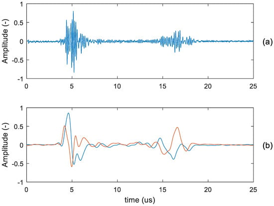
Figure 1.
Raw signal (a) and I/Q demodulated signal (b) acquired from a fluid flowing in an 8 mm diameter pipe investigated with 6 MHz bursts. The strong echoes visible at 5 µs and 16 us are the reflections of the pipe walls; the useful signal of the moving fluid is barely visible in-between the pipe echoes.
The received signal feeds a coherent demodulator that removes the carrier frequency . For example, Figure 1b reports in blue and red the I/Q components produced after coherent demodulation of the signal shown in Figure 1a.
As stated before, the acquisition system, and in particular the analog front-end, the AD converter, and the first step of the numerical data processing chain should accommodate the high signal from the wall and, simultaneously, the low echoes from the fluid. If the dynamics management of the demodulator is not appropriate, the low useful signal fades below the mathematical noise generated by the internal data truncations. This makes the demodulator a critical element in this application.
After demodulation, the I/Q components are processed through spectral estimation to detect . The spectral analysis is performed through the efficient Fast Fourier Transform (FFT) [25,26,27] or more sophisticated adaptive estimators [28,29,30]. The demodulated ultrasound echoes are typically organized in the memory of the processing system along the columns of a matrix. The spectral analysis correlates the signal sampled at the same depth, i.e., proceeding along the rows of such a matrix and producing the power spectra matrix. The latter, color-coded, represents an intuitive picture of the flow profile in the pipe. Its rows report the Doppler shifts, which are proportional to the flow velocity through Equation (1); the columns report the depths inside the pipe. Some examples of spectral matrices are reported later in the experimental section of this paper.
2.2. Coherent Demodulator and CIC Filter Basics
The coherent demodulation [9] is typically obtained by multiplying the input signal si(t) with two sinusoids of frequency FT, affected by a 90° phase difference. In PWD applications the frequency FT typically matches the transmission carrier. Each multiplier is followed by a low-pass filter that eliminates the spectral replica generated by the multiplication. The filtered signals, I(t) and Q(t), represent the phase and quadrature components of the complex output.
The two low-pass filters, implemented in FPGA, process the input signal at the AD converter rate, which can be up to 100 Ms/s. In this condition, the CIC architecture [20] has clear implementation advantages with respect to the standard Finite Impulse Response (FIR) filter [9]. With reference to the Z-domain [9], the basic CIC filter unit is a single integrator-comb (IC) cell, that can be realized as depicted in the graph reported in Figure 2a, where Z–i represents an i-position delay. Basically, the integrator accumulates all of the input samples, while the comb removes from the accumulation the sample delayed of K-positions. The result is the summation of the latest K-samples. The IC cell is described with the following time-discrete equation, corresponding to the Z-domain transfer function :
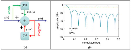
Figure 2.
(a) Integrated-comb (IC) cell of cascaded-IC (CIC) filter and (b) an example of frequency mask obtained for K = 15, which corresponds to normalized cut-off frequency FL = 0.04. Horizontal dashed line represents the −6 dB level.
From Equation (2) it is apparent that the filter cell features a low-pass behavior with transmission zeroes in , i.e., where the normalized frequency fN is i/K, with I = 1,2,3, etc. The side lobes have an amplitude of −13 dB. An example of the cell filter mask is reported in Figure 3b for a cut-off normalized frequency of FL = 0.04, obtained with K = 15.
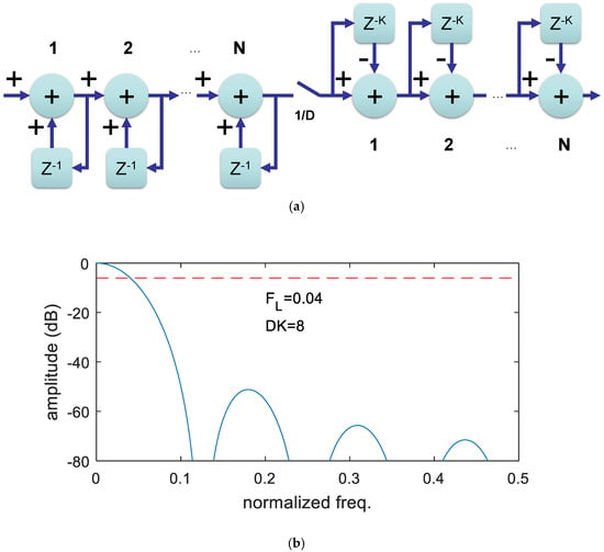
Figure 3.
(a) 4-cell CIC filter and (b) an example of filter masks with DK = 8 for cut-off frequency FL = 0.04. Horizontal dashed line represents the −6 dB level.
In order to overcome the limited performance attainable by a single cell, the decimator CIC filter is normally based on several cells. It is typically realized by separating the integrator and the comb of the single IC cell and rearranging the sequence by cascading several integrators/combs separated by a decimator. The graph of the filter is reported in Figure 3a.
An example of the frequency mask referred to the normalized input frequency, i.e., before applying the spectrum folding due to the decimation, is shown in Figure 3b. For a better comparison, the cut-off frequency is the same as the previous example, i.e., FL = 0.04, now obtained with D·K = 8. The transfer function is:
As demonstrated in reference [20], the filter mathematics should allow a word-growth that corresponds to the gain of the filter, i.e., (D·K)N. In other words, if n is the number of bits used in input to the filter, all of the filter calculations and delay registers should work with a number of bits of:
where ceil(x) is the nearest integer higher than x. For example, the resources for a 4-section complex CIC with K = 64, D = 16 and input data at n = 28 bits include 8 adders at 54 bits and 64·4·54 = 13824 bits of memory employed by the delay registers. Although this architecture can be realized in modern FPGA, it is onerous. In fact, the adders of the integrator sections work at the front-end clock frequency that can reach hundreds of MHz. Hogenauer in reference [20] describes how the number of bits can be safely reduced by truncating the least-significant part of the word. However, the method depends on the specific filter parameters (like K, D, FL, etc.) and is not suitable for a programmable CIC whose FPGA architecture should work with different parameter sets.
2.3. Demodulator Desired Features
The target for the numerical demodulator is the detection of the velocity profiles of fluids flowing in industrial pipes. In general, the demodulator includes the multiplication section and the following filter. However, in practice, the multiplication section is almost ideal and not critical, and all of the complexity resides in the filter. The filter should feature:
- Cut-off frequency programmable in a wide range of frequencies;
- Input dynamic range sufficient for accommodating both the strong pipe echoes and weak fluid signal;
- Low mathematical noise;
- Reasonable FPGA resource utilization;
- Up to 100 MHz working frequency.
3. Methods
3.1. Modified-CIC FilterAarchitecture
In order to face the aforementioned challenges, in this work, we implemented a slightly different CIC filter architecture, as reported in Figure 4. The filter employs 4 single IC cells numbered C1–C4, which include both the integrator and the comb, alternated to 4 decimators. At the output of each cell, a barrel shifter is added. The “Settings Manager” block sets the K0–3 and D1–4 values which establish the mask filter shape; while the “Dynamics Manager” block monitors the data amplitude at every cell output and sets the barrel-shifter according to a control strategy that is detailed in the next section. The transfer function of the modified filter, referred to the input frequency, is:
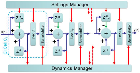
Figure 4.
Modified CIC architecture based on Combo-Integrator sections interconnected by a barrel-shifter and a decimator. A dynamics manager monitors the dynamics in output of every section and operates the barrel-shifters.
An example of a filter mask is reported in Figure 5. It is obtained with K0 = 9, K1 = 5, K2 = 10, K3 = 3, D1 = 1, D2 = 1, D3 = 2, D4 = 1. The normalized cut-off frequency is FL = 0.04 and it can be compared with the corresponding filter mask shown in Figure 3b produced by the standard CIC with 4 cells and B·K = 8. Both filters achieve an attenuation higher than 50 dB outside the main lobes.
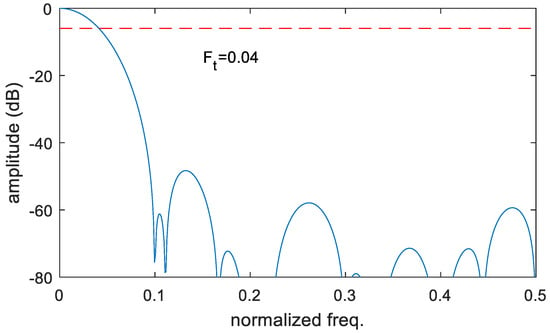
Figure 5.
Filter mask obtained by the CIC architecture of Figure 6 with K0 = 9, K1 = 5, K2 = 10, K3 = 3, D1 = 1, D2 = 1, D3 = 2, D4 = 1. The cut-off normalized frequency is FL = 0.04. Horizontal dashed line represents the –6 dB level.
3.2. Dynamics Management
The dynamics of the filter is one of the key-points for this application. The dynamics management is performed by setting the positions of the barrel-shifters inserted after each IC cell. The goal is to optimize the signal dynamics before the reduction of the bus-width operated on the output of each IC cell. This optimization is in charge of the “Dynamics Manager” block, which can operate according to the 3 different strategies described below. Although the data-adaptive is clearly the approach that grants the best result, coefficient-adaptive and non-adaptive approaches are described as well because they are typically employed in standard CIC and are used in this work for comparison. The strategies are:
(a) Non-adaptive
The most significant bits of the accumulator are selected in output. This is the simplest strategy, and the barrel shifters can be totally removed to save resources in the FPGA. However, bad performance is expected.
(b) Coefficient-adaptive
The barrel shifter position is selected according to the number of accumulations K programmed in the IC cell, i.e., the DC gain of the cell. The maximum word-growth for each cell in bit is ceil(log2(K)). The barrel-shifter is set to accommodate this growth regardless of the dynamics of the actual input data.
(c) Data-adaptive
The barrel-shifters are positioned to accommodate the effective dynamics of the data that are processed. However, the barrel-shifter positions must not change during the PWD measurement session in order to avoid gain steps. Fortunately, the dynamics of the input signal can be considered constant (see Section 2.1) during the duration of a measurement session (typically up to a few minutes). A quick training session was added before the measurement session. First of all the “Settings Manager” block sets the filter parameters (Ki and Di) to establish the filter mask, gain, etc. Then the training session starts. During the first 10 PRIs, the “Dynamics manager” block monitors the data amplitude at the output of the first IC cell, i.e., C1, and saves the maximum value. The “Dynamics manager” block uses the read value to tune the first barrel-shifter at the output of C1. Then, the next 10 PRIs are acquired, and now the “Dynamics manager” block observes the data out of C2, saves the maximum amplitude, and sets the second barrel-shifter. The procedure is repeated in sequence for C3 and C4 and, after 40 PRIs all the barrel-shifters are set for optimal performance. These first PRIs, corrupted by gain steps, are not suitable for Doppler analysis and thus are discarded, but the following are acquired and processed without even stopping the PRIs sequence between the training and acquisition sessions. In a typical set-up, a single PRI lasts about 100–1000 µs, while a complete Doppler measurement involves the acquisition and processing of several thousands of PRIs. Thus, the training session takes no more than 0.1 s of the several hundreds of second that take the whole measurement. The delay due to the filter training is negligible and not perceivable by the final user.
For reader convenience the training procedure is summarized below:
- 1)
- “Setting Manager” block program K0, K1, K2, K3, and D1, D2, D3, D4
- 2)
- Repeat for ICi cells I = 1 to 4:
- Detect the maximum data amplitude on 10 PRIs, M=max(abs(Data))
- Calculate the bits necessary to represent data: J=ceil(log2(M))+1
- Set the shifter so that J is the most significant bit
- Discard the PRIs used for training
- 3)
- Start normal data acquisition and processing
3.3. FPGA Implementation
The demodulator with the modified-CIC architecture was implemented in an FPGA of the Cyclone V family (Intel/Altera, San Jose, CA). The architecture of the single IC cell is detailed in Figure 6. The IC cell is designed to accommodate the worst case of Ki = 64, although the cell can be set for a lower Ki value. The input data bus of width BIi bits feeds a First Input First Output (FIFO) memory and an adder that constitutes the accumulator together with the following register. The delay of K-sample is obtained by generating with the suitable clock-delay the “write” and “read” commands of the FIFO memory that holds the data stream. The adder sums up the input data to the accumulator register value and subtracts the delayed samples coming from the FIFO.
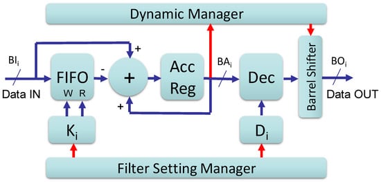
Figure 6.
Details of the IC cell as implemented in the field programmable gate array (FPGA).
The FIFO is sized for holding, in the worst case, 64·BIi bits of input data. An integration factor of K corresponds to a maximum gain of the same value K. The maximum data word-growth is 6 bits. Thus, the adder and the accumulation register work with a bit-width of:
The output of the accumulator is decimated by a programmable factor Di.
BAi = BIi + 6
In each stage of the filter the ICi cell is designed to reduce the input-to-output bus width of 3 bits, i.e.,:
where BOi is the bus-width in output. The combination of Equations (6) and (7) produces:
BOi = BIi − 3
BOi = BAi − 9
Thus, a barrel-shifter with 10 positions covers all of the possible shifts between the accumulator and the output bus. For reader convenience, Figure 7 summarizes the relation among the accumulator, the output bus, and the possible barrel-shifter positions for the three dynamics management strategies reported in Section 3.2.
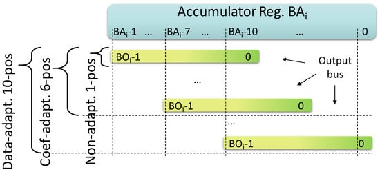
Figure 7.
Barrel-shifter positions for the three different dynamics management strategies. The accumulator of the cell Ci features BAi bits numbered from BAi −1 to 0. The output bus features BOi bits numbered from BOi −1 to 0. The shifter has 1, 6, 10 positions for non-, coeff-, data- adaptive strategies, respectively.
The IC cell is integrated into the demodulator with the bus-widths reported in Figure 8. The data stream si(t) sampled up to 100 Ms/s at 16-bit enters the demodulator. The coherent sin/cos sources are represented at 13-bit. The 2 multipliers produce an output at 16 + 13 − 1 = 28 bits that feed the 2 identical filters composed by 4 sections for the phase and quadrature channels. The filters take in input the 2 buses at 28 bits, and, since each IC stage decreases the bus width of 3 bits, the I/Q signals are outputted at 16 bits. The number of words in FIFO (Mw), the total memory bits in FIFO (Mb), the adder, and accumulator width (BA), and the barrel-shifter positions for data-adaptive strategy (BS) are reported in Figure 8 inside the graphical blocks of each specific IC cell in the filter chain.
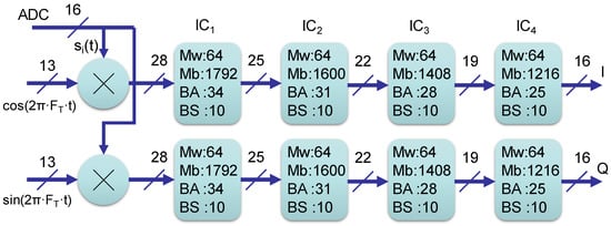
Figure 8.
Architecture of the data-adaptive demodulator. IC cells report the memory words (Mw), the memory bits (Mb), the accumulator width (BA), and the barrel-shifter (BS) positions. The bus-widths in input and output of each IC cell are reported as well.
4. Experiments and Results
4.1. Resources Utilization
The first experiment aimed at evaluating the resource utilization of the proposed solutions. The demodulator of Figure 8 was implemented in an FPGA of the Cyclone V family (Altera/Intel, San Jose, CA, USA) in all of the three configurations for dynamics management described in Section 3.2. The design was targeted for a clock up to 100 MHz, a goal easily reached for all of the implementations. The results are listed in Table 1, distinguished for Adaptive Logic Modules (ALM), Adaptive Look-up-Tables (ALUT), Registers (REG), Memory bits, and Digital Signal Processors (DSP) blocks. In all of the implementations two DSP blocks are employed for the two multipliers of the demodulator (see, e.g., Figure 8). The memory bits (17,700 for the proposed architecture) are more than the sum of the memory bits listed in Figure 8. This is due to the internal organization of FPGA memory. The data-adaptive and coeff-adaptive approaches have a similar resource utilization, while the non-adaptive approach employs fewer resources since the barrel-shifters are removed.

Table 1.
Demodulator resources utilization in FPGA implementation.
4.2. Demodulator Noise Performance
This experiment aimed to evaluate the noise produced by the finite number representation in the mathematical calculations of the filter. The system for rheological fluid characterization described in reference [23] was connected to a flow-rig. A fluid composed by demineralized water with added specific ultrasonic scatters flowed in an 8 mm diameter pipe moved by a gear pump. The pipe was immersed in a water tank where a cylindrical ultrasound transducer was directed towards the pipe at an angle of 60° with respect to the pipe axis. The transducer was excited by the system with bursts composed by 5 cycles at 6 MHz, repeated with a PRIs of 200 µs. The received echoes were sampled at 16 bits 100 Ms/s. The analog gain of the front-end of the system was accurately tuned with a manual try-and-check procedure to exploit the full 16 bits dynamic range of the AD converter. An example of the signal acquired in a PRI is shown in Figure 1a.
The acquired signal was used to generate three different test signals. The first, hereafter named ‘S16’ was the original signal itself, the second and the third signals, named ‘S12’ and ‘S08’ were obtained by reducing the dynamics of the original signal to 12 and 8 bits, respectively. This was obtained by dividing the data to 24 and 28 but maintaining the 16 bits word representation. These last two signals mimic a non-optimal tuning of the analog input gain of the front-end of the system.
The demodulators were coded in VHDL language and implemented in Modelsim® (Mentor Graphics Corp. Wilsonville 97070 OR). The filter parameters were set to obtain FL = 0.01, that, for a 100 MHz sampling frequency, corresponds to a 1 MHz bandwidth. The employed parameters are detailed in Table 2.

Table 2.
Filter parameter employed in experiments.
The 3 test signals were processed according to all of the 3 strategies for dynamics management. The corresponding demodulated outputs were named SDxx, where xx is 16, 12, and 08 and indicate the corresponding input signal. The demodulator was implemented in Matlab® (The Mathworks, Natick, MA, USA) as well, and used to process the test signals in double precision. These results were considered as reference and named SDRxx. The signals were compared in Matlab® by computing the Signal-to-Noise ratio with the following metric:
Please note that the reference output signals SDRxx were generated by the ideal Matlab® demodulator with the Sxx signals quantized at 16, 12, 08 bits. Thus, the quantization input noise is not included in the SNR evaluated by (9). SNR calculated by Equation (9) accounts for the mathematical noise of the demodulator and the final 16-bit quantization noise. The results, expressed in dB, are listed in Table 3. In addition, the maximum SNR achievable for the signals present in this application was further calculated in Matlab®. The output of the ideal demodulator SDRxx with in input the S16 signal was normalized at full dynamics and quantized at 16 bits. The SNR due to this quantization was calculated and reported in the last column of Table 3 (Reference). Note that the typical formula 6.02∙N + 1.76 (where N is the number of bits) [9] results in SNR = 98.1 dB instead of 85.0 dB for N = 16 bits. In fact, the aforementioned formula is valid for a full-dynamics sinusoidal signal, while the actual signal used here exploits the full dynamics only for a small part of the acquired period (see Figure 1a).

Table 3.
Signal-to-noise ratio (SNR) Performance of the demodulator–input quantization excluded.
The performance in non-adaptive approach (see Table 3) is particularly bad, being the maximum SNR = 25 dB only. Since that the ratio between pipe and fluid echoes is up to 30–40 dB, the non-adaptive approach is not suitable for the application. The coef-adaptive strategy grants much better performance and reaches SNR = 60 dB in the best condition. However, the SNR degrades quickly when the input data scales-down. The coef-adaptive strategy is sensitive to input data dynamics and thus it is not so robust for industrial applications. The data-adaptive approach produces the best performance achieving an SNR = 84 dB. Most importantly, the performance does not depend on the input dynamics even at 8 bits of input data. Moreover, the predominant noise is generated by the 16 bits quantization in output, and not from the finite numerical representation of the filter mathematics. This confirms that data-adaptive performance is quite close to the reference (see Table 3).
The noise performance of the demodulators is further confirmed by positions of the barrel shifter present during the experiment and listed in Table 4. Each BSi column reports the position of the barrel-shifter at the end of the cell ICi. A value of m in the table means that the shifter scales the signal by 2−m.

Table 4.
Scaling positions of the barrel shifters.
In non-adaptive strategy, the scaling is fixed to 2−9, i.e., the 6 positions related to the maximum filter gain (Ki up to 64) plus 3 for the bus-width reduction (7). In the coeff-adaptive approach, the positions correspond to the actual filter settings, plus the 3 positions for bus-width reduction. For example, since K0 = 32 (see Table 2), BS1 = ceil (log2(32)) + 3 = 8. However, the settings are the same regardless of the input signal Sxx. In a data-adaptive approach the filter positions change for different rows of Table 4, i.e., they depend on the signal dynamics. BS1 scales 7 positions for the strong signal S16, but 0 positions for S08, thus recovering 7 bits of dynamics. BS2 scales 6 positions for S08 and 7 for the other signals. BS3 and BS4 have the same behavior for all the signals. This means that the dynamics of S08 is recovered mostly by BS1 and BS2. Then BS3 and BS4 scale 6 positions like for the other signals. This explains how the demodulator achieves the best performance of 83.4 dB when processing S08 (see Table 3).
4.3. Flow Simulation
The performance of the demodulator was tested in a flow simulation. The simulation was carried out in Matlab® through the Field II ultrasound simulator [31,32], freely available at https://field-ii.dk. Field II, given the position of a set of scattering particles, the transducer characteristics, and the TX pulse, simulates the echo data acquired in each PRI. In this test, a piston transducer transmitted bursts of 5 cycles at 6 MHz in a 45 mm diameter pipe. The positions of the scattering particles were updated every PRI to mimic the typical parabolic profile of a Newtonian fluid flowing in a straight pipe [33]. The peak velocity was set to 1 m/s. A 16-bit AD converter was simulated by scaling the amplitude of the data generated by Field II and by applying the 16 bits fixed point representation. Two data sets were generated: The first was composed by the echoes from the particles in the flow only, while the other included the echoes from the static pipe wall as well. The power ratio between echoes from pipe wall and from flow particles was 35 dB.
The two data sets were processed by both the non-adaptive and by the data-adaptive demodulators. The demodulators were programmed with the same integration and decimation parameters used in the previous experiment. Four power spectral matrices were obtained and reported in Figure 9 in color code. The vertical axes show the depth along the pipe diameter, while the horizontal axes report the velocity obtained by converting the Doppler shift through (1).
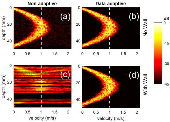
Figure 9.
Power spectral matrices obtained for a simulated parabolic flow with 1 m/s peak velocity in a 45 mm diameter pipe. In (c,d) the signal from a static pipe-wall is added with a power 35 dB higher than the flow signal; in (a,b) the only flow signal is present. (a,c) are obtained with non-adaptive demodulator; (b,d) with data-adaptive demodulator. Horizontal axes report the Doppler shift converted to velocity. Vertical dashed lines correspond to the simulated peak velocity.
The simulated signal without the pipe wall echoes produces spectral matrices where the parabolic profile can be clearly detected (Figure 9a,b). When the pipe wall signal is added, the data-adaptive demodulator produces a spectral matrix (Figure 9d) that is identical to the case without the wall signal (Figure 9b). On the other hand, the non-adaptive demodulator does not produce a detectable profile when the pipe wall is added (Figure 9c). Background noise is quite high and several regions (black horizontal bands) are below the filter sensitivity. Moreover, whenever the velocity profile is detected (Figure 9a,b,d) the velocity that corresponds to the parabola peak is located with an accuracy of ±2.2%. For comparison, the reference velocity of 1 m/s is reported by the vertical dashed lines.
4.4. Example of Application
The proposed demodulator was included in the processing chain of the system for the detection of the velocity profile of fluids flowing in pipes described in reference [34]. The system was connected to the flow-rig as described in Section 4.2. The demodulator was programmed with the same integration and decimation parameters used in the previous experiment. The analog gain of the front-end was tuned to reproduce the 16, 12, 08 bits input signal dynamics, and the filter was set for non-, coeff-, data- adaptive approaches. Frames of power spectral matrices elaborated in real-time by the system were captured and reported in Figure 10.
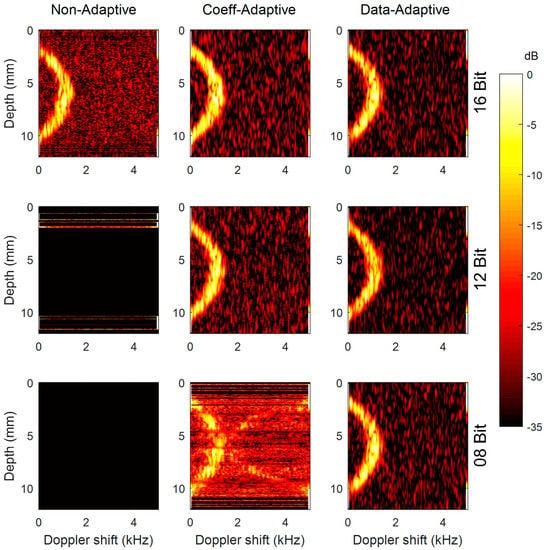
Figure 10.
Power spectral matrices calculated by the system, including the proposed demodulator. Horizontal and vertical axes report Doppler shift and depth, respectively. Matrices processed with non-, coeff-, data- adaptive strategies are reported in columns; input signal equivalent to 16, 12, 08 bits are reported in rows.
The spectral matrices show the typical parabolic profile of a Newtonian fluid. When the input gain is tuned for exploiting the full dynamics of the AD converter (16 bits, first row in Figure 10), the parabolic profile is clearly detected regardless of the dynamic’s management employed in the filter. The non-adaptive configuration features a higher noise level, the other two cases are similar. When the input signal covers 12 bits of the AD dynamics, coef- and data- adaptive approaches do not show appreciable deterioration, while a non-adaptive approach shows no usable signal. With input dynamics at 8 bits, coeff-adaptive approach features a very high noise level, while data-adaptive showed no visible difference with respect to previous analysis. In other words, non-adaptive demodulator produces a good signal only when the full input dynamics is exploited; data-adaptive demodulators produce the same high-quality signal even if the input dynamics is reduced to only 8 bits. The coeff-adaptive approach produces intermediate results.
5. Discussion and Conclusion
In this work, a data-adaptive demodulator for PWD applications is presented. A “training phase” is used to read the dynamics of the actual signal and tune accordingly the internal barrel-shifters. It is followed by the “running phase” where the signal is effectively processed with the gain parameters set in the training phase. The training phase is very quick and precedes the normal acquisition phase without impact to the final application.
The superior performance of the proposed method is evident in presence of strong pipe-wall echoes, as shown in the simulation of Section 4.3. The simulation highlights that the non-adaptive demodulator fails while the data-adaptive detects the correct velocity profile. In fact, in the presence of a strong pipe wall echo, the dynamics of the useful flow signal is reduced proportionally to the amplitude of the disturbing echo. If the dynamics are reduced beyond the SNR limits reported in Table 3, the profile detection is prevented because the signal is concealed in the noise. The high SNR performance of the data-adaptive approach is confirmed also in the experiment on a real pipe flow, whose results are shown in Figure 10. The data-adaptive approach allows us to recover the optimal signal at the demodulator output even when the signal at the AD converter input uses only 8 bits. In this condition, nor the coeff-adaptive, neither the non-adaptive approaches, can produce any usable signal. This is a very important feature in industrial applications, where the PWD system is expected to work with minimal tuning and to be robust to a wide range of conditions.
The data-adaptive approach can also be implemented with a single barrel-shifter at the end of a standard 4-stage CIC architecture, however, this approach would require more FPGA resources. Floating point mathematical calculations [35,36,37] would grant even better performance. However, although recent high-end FPGAs integrates floating-point hard-processors, the resources needed are by far higher than those employed in the proposed solution. Thus, floating point approach is, at present, not cost-effective.
The presented demodulator fulfils the requirements reported in Section 2.3. It includes a filter with a programmable mask, it can be easily implemented in low-cost FPGA, and it features a data throughput up to 100 Ms/s. Most importantly, the data-adaptive approach is not affected by the strong pipe echoes and is capable of auto-tuning for the widest range of input conditions, reducing the intervention of specialized workers. The proposed demodulator can represent a valuable processing block for industrial applications where high dynamics is an essential precondition.
Author Contributions
Conceptualization, methodology, writing paper, funding acquisition: S.R.; software, investigation, data curation: V.M.
Funding
This work is funded by the Ministero dell’Istruzione, dell’Università e della Ricerca (MIUR) of Italy Government.
Acknowledgments
Authors thank Johan Wiklund for his advice about fluid rheology.
Conflicts of Interest
The authors declare no conflict of interest. The funders had no role in the design of the study; in the collection, analyses, or interpretation of data; in the writing of the manuscript, and in the decision to publish the results.
References
- Evans, D.H.; McDicken, W.N. Doppler Ultrasound Physics, Instrumentation and Signal Processing; Wiley: Chichester, UK, 2000; ISBN 978-0471970019. [Google Scholar]
- Vogt, M. Direct sampling and baseband conversion in Doppler systems for high-frequency ultrasound blood flow measurements. Electron. Lett. 2005, 41, 189–790. [Google Scholar] [CrossRef]
- Weibao, Q.; Zongying, Y.; Yanyan, Y.; Yan, C.; Liyang, C.; Peitian, M.; Guofeng, L.; Congzhi, W.; Yang, X.; Jiyan, D.; et al. A Digital Multigate Doppler Method for High Frequency Ultrasound. Sensors 2014, 14, 13348–13360. [Google Scholar] [CrossRef]
- Boni, E.; Bassi, L.; Dallai, A.; Meacci, V.; Ramalli, A.; Scaringella, M.; Guidi, F.; Ricci, S.; Tortoli, P. Architecture of an Ultrasound System for Continuous Real-Time High Frame Rate Imaging. IEEE Trans. Ultrason. Ferroelectr. Freq. Control 2017, 64, 1276–1284. [Google Scholar] [CrossRef] [PubMed]
- Jensen, J.A.; Nikolov, S.I.; Yu, A.C.H.; Garcia, D. Ultrasound Vector Flow Imaging-Part II: Parallel Systems. IEEE Trans. Ultrason. Ferroelectr. Freq. Control 2016, 63, 722–1732. [Google Scholar] [CrossRef] [PubMed]
- Hervás, M.; Alsina-Pagès, R.M.; Salvador, M. An FPGA Scalable Software Defined Radio Platform Design for Educational and Research Purposes. Electronics 2016, 5, 27. [Google Scholar] [CrossRef]
- Koulamas, C.; Lazarescu, M.T. Real-Time Embedded Systems: Present and Future. Electronics 2018, 7, 205. [Google Scholar] [CrossRef]
- Rodriguez-Andina, J.J.; Moure, M.J.; Valdes, M.D. Features, design tools, and application domains of FPGAs. IEEE Trans. Ind. Electron. 2007, 54, 1810–1823. [Google Scholar] [CrossRef]
- Richard, L. Understanding Digital Signal Processing, 2nd ed.; Prentice Hall: Upper Saddle River, NJ, USA, 2004; ISBN 978-0-13-702741-5. [Google Scholar]
- Mohsin, A.; Fadhel, M.G.; Mohamed, H. Blind Compensation of I/Q Impairments in Wireless Transceivers. Sensors 2017, 17, 2948. [Google Scholar] [CrossRef]
- Ricci, S.; Matera, R.; Tortoli, P. An improved Doppler model for obtaining accurate maximum blood velocities. Ultrasonics 2014, 7, 2006–2014. [Google Scholar] [CrossRef]
- Wiklund, J.; Stading, M. Application of in-line ultrasound Doppler-based UVP–PD rheometry method to concentrated model and industrial suspensions. Flow Meas. Instrum. 2008, 19, 171–179. [Google Scholar] [CrossRef]
- Birkhofer, B.; Debacker, A.; Russo, S.; Ricci, S.; Lootens, D. In-line rheometry based on ultrasonic velocity profiles: Comparison of data processing methods. Appl. Rheol. 2012, 22, 44701. [Google Scholar] [CrossRef]
- Morganti, T.; Ricci, S.; Vittone, F.; Palombo, C.; Tortoli, P. Clinical validation of common carotid artery wall distension assessment based on multigate Doppler processing. Ultras. Med. Biol. 2005, 31, 937–945. [Google Scholar] [CrossRef] [PubMed]
- Shamu, T.J.; Kotzé, R.; Wiklund, J. Characterization of acoustic beam propagation through high-grade stainless steel pipes for improved pulsed ultrasound velocimetry measurements in complex industrial fluids. IEEE Sens. J. 2016, 16, 5636–5647. [Google Scholar] [CrossRef]
- Kotzé, R.; Ricci, S.; Birkhofer, B.; Wiklund, J. Performance tests of a new non-invasive sensor unit and ultrasound electronics. Flow Meas. Instrum. 2016, 48, 104–111. [Google Scholar] [CrossRef]
- Qwist, P.K.; Sander, C.; Okkels, F.; Jessen, V.; Baldursdottir, S.; Rantanen, J. On-line rheological characterization of semi-solid formulations. Eur. J. Pharm. Sci. 2019, 128, 36–42. [Google Scholar] [CrossRef] [PubMed]
- Ricci, S.; Swillens, A.; Ramalli, A.; Segers, P.; Tortoli, P. Wall Shear Rate Measurement: Validation of a new Method through Multi-physics Simulations. IEEE Trans. Ultrason. Ferroelectr. Freq. Control 2017, 64, 66–77. [Google Scholar] [CrossRef] [PubMed]
- Meacci, V.; Matera, R.; Ricci, S. High dynamics adaptive demodulator for ultrasound applications: FPGA implementation. In Proceedings of the 1st New Generation of CAS, NGCAS, Genoa, Italy, 6–8 September 2017. [Google Scholar]
- Hogenauer, E. An economical class of digital filters for decimation and interpolation. IEEE Trans. Acoust. Speech Signal Process. 1981, 29, 155–162. [Google Scholar] [CrossRef]
- Peilu, L.; Xinghua, L.; Haopeng, L.; Zhikun, S.; Hongxu, Z. Implementation of High Time Delay Accuracy of Ultrasonic Phased Array Based on Interpolation CIC Filter. Sensors 2017, 17, 2322. [Google Scholar] [CrossRef]
- Pilato, L.; Fanucci, L.; Saponara, S. Real-Time and High-Accuracy Arctangent Computation Using CORDIC and Fast Magnitude Estimation. Electronics 2017, 6, 22. [Google Scholar] [CrossRef]
- Ricci, S.; Meacci, V.; Birkhofer, B.; Wiklund, J. FPGA-based System for In-Line Measurement of Velocity Profiles of Fluids in Industrial Pipe Flow. IEEE Trans. Ind. Electron. 2017, 64, 3997–4005. [Google Scholar] [CrossRef]
- Ricci, S.; Liard, M.; Birkhofer, B.; Lootens, D.; Brühwiler, A.; Tortoli, P. Embedded Doppler System for Industrial in-Line Rheometry. IEEE Trans. Ultrason. Ferroelectr. Freq. Control 2012, 59, 1395–1401. [Google Scholar] [CrossRef]
- Cooley, J.W.; Tukey, J.W. An algorithm for the machine calculation of complex Fourier series. Math. Comput. 1965, 19, 297–301. [Google Scholar] [CrossRef]
- Minotta, F.; Jimenez, M.; Rodriguez, D. Automated Scalable Address Generation Patterns for 2-Dimensional Folding Schemes in Radix-2 FFT Implementations. Electronics 2018, 7, 33. [Google Scholar] [CrossRef]
- Nguyen, H.N.; Khan, S.A.; Kim, C.H.; Kim, J.M. A Pipelined FFT Processor Using an Optimal Hybrid Rotation Scheme for Complex Multiplication: Design, FPGA Implementation and Analysis. Electronics 2018, 7, 137. [Google Scholar] [CrossRef]
- Ricci, S. Adaptive Spectral Estimators for Fast Flow Profile Detection. IEEE Trans. Ultrason. Ferroelectr. Freq. Control 2013, 60, 421–427. [Google Scholar] [CrossRef] [PubMed]
- Elif, D.Ü.; Hakan, I.; İnan, G. Application of FFT and Arma Spectral Analysis to Arterial Doppler Signals. Math. Comput. Appl. 2003, 8, 311–318. [Google Scholar] [CrossRef]
- Larsson, E.; Stoica, P. Fast implementation of two-dimensional APES and Capon spectral estimators. Multidimens. Syst. Signal Process. 2002, 13, 35–54. [Google Scholar] [CrossRef]
- Jensen, J.A.; Svendsen, N.B. Calculation of pressure fields from arbitrarily shaped, apodized, and excited ultrasound transducers. IEEE Trans. Ultrason. Ferroelect. Freq. Control 1992, 39, 262–267. [Google Scholar] [CrossRef] [PubMed]
- Jensen, J.A. Field: A Program for Simulating Ultrasound Systems. Med. Biol. Eng. Comp. 1996, 34, 351–353. [Google Scholar]
- Granger, R.A. Fluid Mechanics; Dover: Mineola, NY, USA, 1995; ISBN 978-0486683560. [Google Scholar]
- Meacci, V.; Ricci, S.; Wiklund, J.; Birkhofer, B.; Kotze, R. Flow-Viz—An integrated digital in-line fluid characterization system for industrial applications. In Proceedings of the 11th IEEE Sensors Applications Symposium (SAS), Catania, Italy, 13–15 April 2016; pp. 128–133. [Google Scholar]
- 754-2008—IEEE Standard for Floating-Point Arithmetic. 2008. Available online: https://doi.org/10.1109/IEEESTD.2008.4610935 (accessed on 12 December 2018).
- Al Kadi, M.; Janssen, B.; Huebner, M. Floating-Point Arithmetic Using GPGPU on FPGAs. In Proceedings of the IEEE Computer Society Annual Symposium on VLSI, ISVLSI, Bochum, Germany, 3–5 July 2017; pp. 134–139. [Google Scholar]
- Sanchez, A.; Todorovich, E.; De Castro, A. Exploring the Limits of Floating-Point Resolution for Hardware-In-the-Loop Implemented with FPGAs. Electronics 2018, 7, 219. [Google Scholar] [CrossRef]
© 2018 by the authors. Licensee MDPI, Basel, Switzerland. This article is an open access article distributed under the terms and conditions of the Creative Commons Attribution (CC BY) license (http://creativecommons.org/licenses/by/4.0/).