Article

Preliminary Design of an Unmanned Aircraft System for Aircraft General Visual Inspection

1
Department of Science and Technology, University of Naples “Parthenope”, 80143 Naples, Italy
2
Department of Engineering, University of Campania “L. Vanvitelli”, 81031 Aversa (CE), Italy
*
Author to whom correspondence should be addressed.
Electronics 2018, 7(12), 435; https://doi.org/10.3390/electronics7120435
Submission received: 26 October 2018 / Revised: 3 December 2018 / Accepted: 13 December 2018 / Published: 14 December 2018
(This article belongs to the Special Issue Autonomous Control of Unmanned Aerial Vehicles)

Abstract

:
Among non-destructive inspection (NDI) techniques, General Visual Inspection (GVI), global or zonal, is the most widely used, being quick and relatively less expensive. In the aeronautic industry, GVI is a basic procedure for monitoring aircraft performance and ensuring safety and serviceability, and over 80% of the inspections on large transport category aircrafts are based on visual testing, both directly and remotely, either unaided or aided via mirrors, lenses, endoscopes or optic fiber devices coupled to cameras. This paper develops the idea of a global and/or zonal GVI procedure implemented by means of an autonomous unmanned aircraft system (UAS), equipped with a low-cost, high-definition (HD) camera for carrying out damage detection of panels, and a series of distance and trajectory sensors for obstacle avoidance and inspection path planning. An ultrasonic distance keeper system (UDKS), useful to guarantee a fixed distance between the UAS and the aircraft, was developed, and several ultrasonic sensors (HC-SR-04) together with an HD camera and a microcontroller were installed on the selected platform, a small commercial quad-rotor (micro-UAV). The overall system concept design and some laboratory experimental tests are presented to show the effectiveness of entrusting aircraft inspection procedures to a small UAS and a PC-based ground station for data collection and processing.

1. Introduction

General Visual Inspection (GVI) is a common method of quality control, data acquisition and data analysis, involving raw human senses such as vision, hearing, touch, smell, and/or any non-specialized inspection equipment. Unmanned aerial systems (UAS), i.e., unmanned aerial vehicles (UAV) equipped with the appropriate payload and sensors for specific tasks, are being developed for automated visual inspection and monitoring in many industrial applications. Maintenance Steering Group-3 (MSG-3), a decision logic process widely used in the airline industry [1], defines GVI as a visual examination of an interior or exterior area, installation or assembly to detect obvious damage, failure or irregularity, made from within touching distance and under normally available lighting condition such as daylight, hangar lighting, flashlight or drop-light [2]. As stated by the Federal Aviation Administration (FAA) Advisory Circular 43-204 [3], visual inspection of aircrafts is used to:
-
Provide an overall assessment of the condition of a structure, component, or system;
-
Provide early detection of typical airframe defects (e.g., cracks, corrosion, engine defects, missing rivets, dents, lightning scratches, delamination, and disbonding) before they reach critical size;
-
Detect errors in the manufacturing process;
-
Obtain more information about the condition of a component showing evidence of a defect.
As far as aircraft maintenance, safety and serviceability are concerned, entrusting GVI tasks to a UAS with hovering capabilities may be a good alternative, allowing more accurate inspection procedures and extensive data collection of damaged structures [4]. Traditional aircraft inspection processes, performed in hangars from the ground or using telescopic platforms, can typically take up to 1 day, whereas drone-based aircraft GVI could significantly reduce the inspection time. Moreover, a recent study [5] quantified aircraft visual inspection error rates up to 68%, classifying them as omissions (missing a defect) rather than commissive errors (false alarms, i.e., flagging a good item as defective). The use of a reliable automatic GVI procedure with a UAS could substantially lower the incidence of omissions, which could be catastrophic for aircraft serviceability, whereas false positives, or commissive errors, are not a major concern. From this standpoint, the development of a drone-based GVI approach is justified by the following aspects:
-
Reduced aircraft permanence in the hangar and reduced cost of conventional visual inspection procedures;
-
accelerated and/or facilitated visual checks in hard-to-reach areas, increased operator safety;
-
possibility of designing specific and reproduceable inspection paths around the aircraft, capturing images at a safe distance from the structures and at different viewpoints, and transmitting data via dedicated links to a ground station;
-
accurate defect assessment by comparing acquired images with 3D structural models of the airplane;
-
ease of use, no pilot qualification needed;
-
possibility of gathering different information by installing on the UAV cost-effective sensors (thermal cameras, non-destructive testing sensors, etc.);
-
increased quality of inspection reports, real-time identification of maintenance issues, damage and anomalies comparison with previous inspections;
-
possibility of producing automatic inspection reports and performing accurate inspections after every flight.
Ease of access to the inspection area is important in obtaining reliable GVI procedures. Access consists of the act of getting into an inspection position (primary access) and performing the visual inspection (secondary access). Unusual and unreachable positions (i.e., crouching, lying on back, etc.) are examples of difficult primary access [3].
This paper describes the preliminary design of a GVI system onboard a commercial VTOL (Vertical Take-Off and Landing) UAV (a quadrotor). The experimental setup is composed of a ground station (PC-based), an embedded control system installed on the airframe, and sensors devoted to GVI. To ensure a minimum safety distance from the aircraft is inspected, an ultrasonic distance keeper system (UDKS) has been designed. A high-definition (HD) camera will detect visual damage caused by hail strikes or lightning strikes, which are among the most dangerous threats for the airframe. The incidence of lightning strikes on aircrafts in civil operation is of the order of one strike per aircraft per year, whereas hail strikes are much more common and dangerous. The hovering UAS will be pushed along the fuselage and wings, and the vehicle automatically maintains a safe standoff distance from the aircraft due to ultrasonic sensors which are part of the devised UDKS.
The paper is structured as follows: After justifying in the Introduction the use of a UAV-based aircraft inspection system, a Background (Section 2) focuses on literature review of related work. In Section 3, the chosen UAV, the GVI equipment and the UDKS are presented. Section 4 shows preliminary results obtained from initial test flights, evaluating the performance of the UDKS and of the image acquisition/processing module for damage detection. Conclusions and further developments as outlined in Section 5.

2. Background

The potential for UAV-based generation of high-quality images of structural details to detect structural damage and support condition assessment of civil structures is very high, particularly in difficult-to-access areas [6]. Drone-based visual inspection is used for monitoring oil and gas platforms [7], drilling rigs, pipelines [8], transmission networks [9], infrastructures like bridges [10] and buildings [11], assessing road conditions [12], 3D mapping of pavement distresses [13], inspecting power lines [14] and equipment [15], photovoltaic (PV) plants [16], cracks in concrete civil infrastructures [17], construction sites [18], elevators [19], as well as viaducts, subways, tunnels, level crossings, dams, reservoirs, etc. [20]. Integration of Unmanned Ground Vehicles (UGV) and UAVs is also being exploited for industrial inspection tasks [21].
Nowadays, a broad range of UAVs exist, from small and lightweight fixed-wing aircraft to rotor helicopters, large-wingspan airplanes and quadcopters, each one for a specific task, generally providing persistence beyond the capabilities of manned vehicles [22]. UAVs can be categorized with respect to mass, range, flight altitude, and endurance (Table 1).
VTOL aircrafts offer many advantages over Conventional Take-Off and Landing (CTOL) vehicles, mainly due to the small area required for take-off and landing, and the ability to hover in place and fly at very low altitudes and in narrow, confined spaces. Among VTOL aircrafts, such as conventional helicopters and crafts with rotors like the tiltrotor and fixed-wing aircraft with directed jet thrust capability, the quadrotor, or quadcopter, is very frequently chosen, especially in academic research on mini or micro-size UAVs, as an effective alternative to the high cost and complexity of conventional rotorcrafts, due to its ability to hover and move without the complex system of linkages and blade elements present in single-rotor vehicles [25,26,27]. Quadrotors are widely used in close-range photogrammetry, search and rescue operations, environment monitoring, industrial component inspection, etc., due to their swift maneuverability in small areas. The quadrotor has good ranking among VTOL vehicles, yet it has some drawbacks. The craft size is comparatively larger, energy consumption is greater, implying lower flight time, and the control algorithms are very complicated due to the fact that only four actuators are used to control all six degrees of freedom (DOF) of the quadrotor (which is classified as an underactuated system), and that the changing aerodynamic interference patterns between the rotors have to be taken into account [26,28,29,30].

3. UAV and GVI Equipment

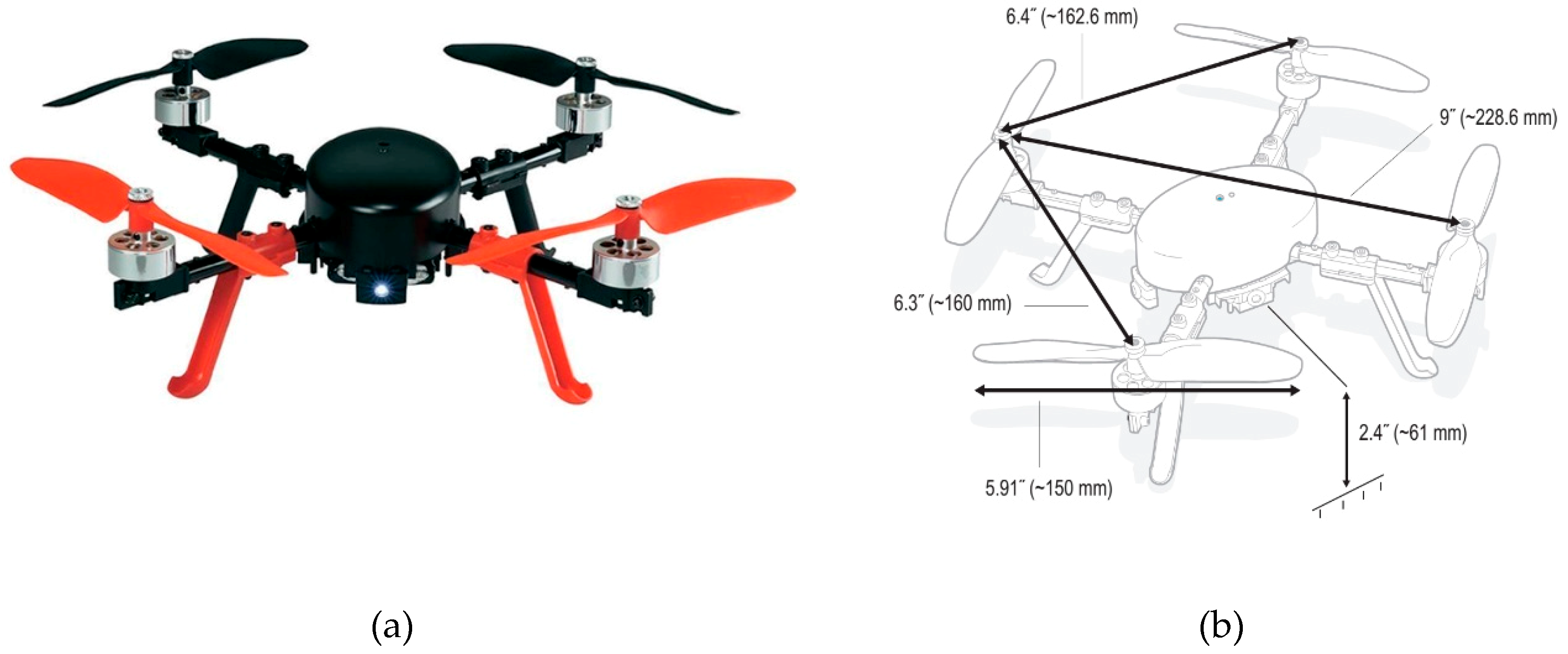
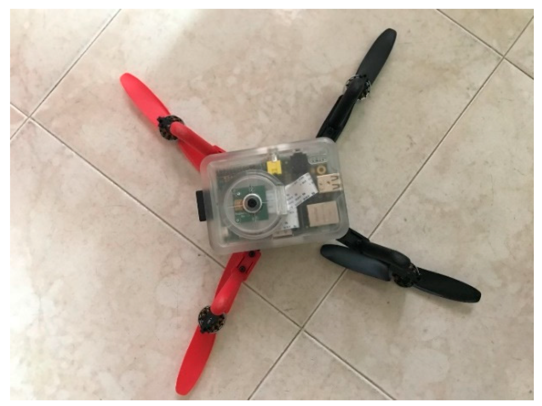
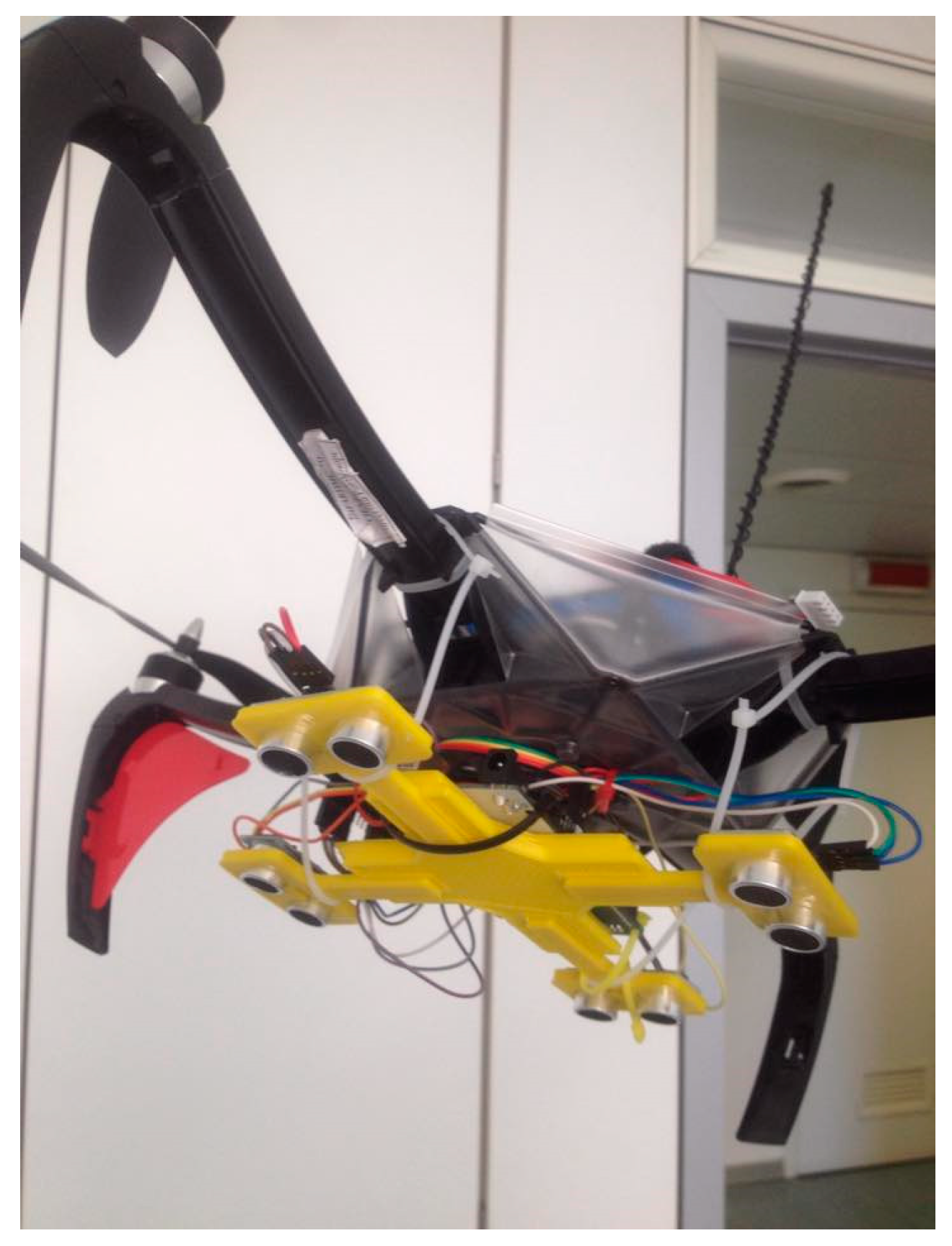
3.1. Unmanned Aerial Vehicle

The unmanned aircraft chosen for this application is a micro-UAV (MAV, see Table 1) quadrotor, model “RC EYE One Xtreme” (Figure 1), produced by RC Logger [31]. It spans 23 cm from the tip of one rotor to the tip of the opposite rotor; has a height of 8 cm, a total mass of 260 g; with a 100-g, 7.4-V LiPo battery; and a payload capacity of 150 g. Typical flight time is of the order of 10 min, with a 1150-mAh battery and the payload. This vehicle consolidates rigid design, modern aeronautic technology as well as easy maintainability into a versatile multi-rotor platform, durable enough to survive most crashes. Six-axis gyro stabilization technology and a robust brushless motor-driven flight control are embedded within a rugged yet stylish frame design. The One Xtreme is an ideal platform for flight applications (the maximum transmitter range is approximately 150 m in free field) ranging from aerial surveillance, imaging or simply unleashing acrobatic fun flight excitement. A low-level built-in flight control system can balance out small undesired changes to the flight altitude, and allows one to select three flight modes: beginner, sport and expert. In this work, all experimental data sessions were performed flying the UAV in the beginner’s mode.
The One Xtreme can be operated both indoors and outdoors during calm weather conditions, since the empty weight of the UAV (260 g) makes it react sensitively to wind or draughts. In order to control and manage all the phases of flight during a GVI session (in particular, the landing procedure and the cruise at a fixed distance from the fuselage of the aircraft to be inspected), a distance acquisition system using sonic ranging (SR) sensors was built and tested.

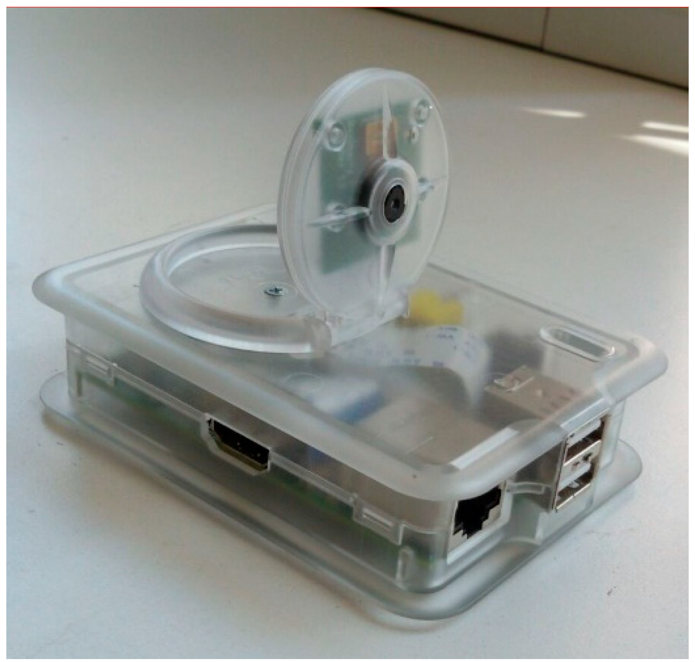
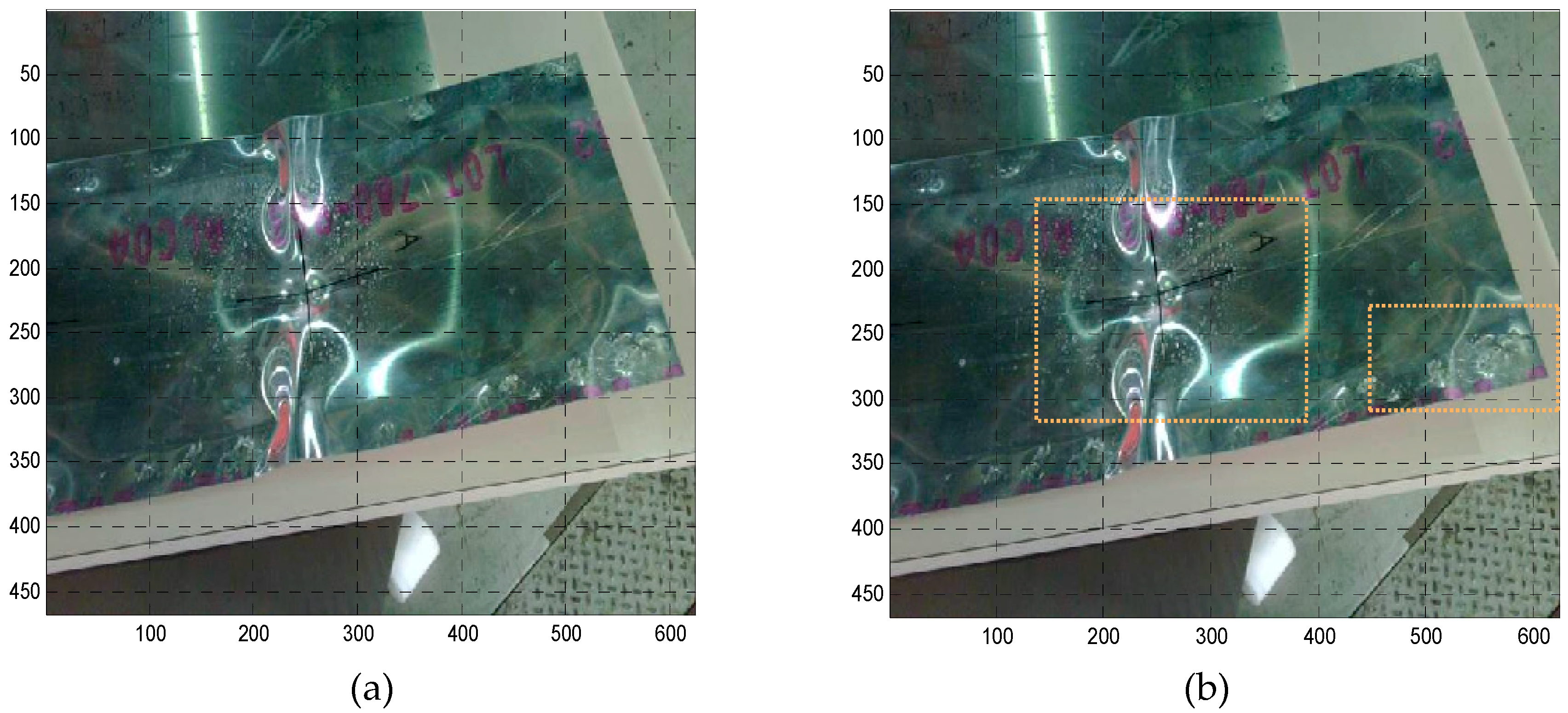
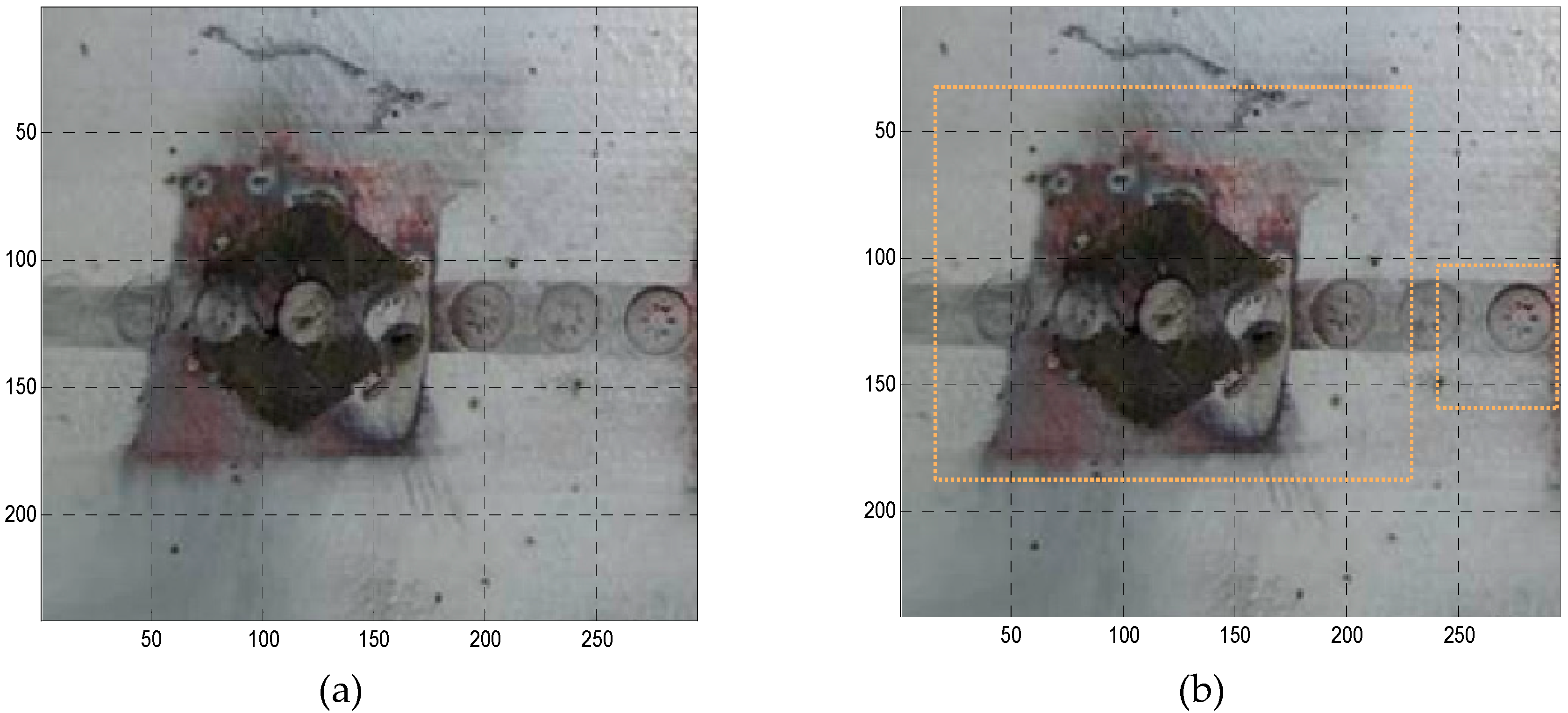
3.2. GVI and Image Processing Equipment

The image acquisition subsystem devised for the GVI equipment consists of a Raspberry Pi Camera Module v2, released in 2016 [32], mounted on a small single-board computer, the Raspberry Pi 2 Model B [33], with a 900-MHz quad-core ARM Cortex-A7 CPU, 1-GB RAM, two USB ports, and a camera interface (CSI port, located behind the Internet port) with dedicated camera software. A Wi-Fi dongle was installed on the Raspberry board for real-time transmission of images to the PC-based control station. The total weight of the image acquisition hardware (close-range camera, computer module and case) is 50 g.
Table 2 reports some technical specifications of the Pi Camera Module v2. The module allows manual control of the focal length, in order to set up specific and constant values. It can acquire images with a maximum resolution of about 6 Megapixels at a maximum rate of 90 frames per second. To avoid buffer overload and excessive computational cost, the resolution was set to 1920 × 1080 (2 Megapixel), corresponding to HD video. Figure 2 and Figure 3 show the standalone assembled image acquisition system and the installation on the quadrotor, respectively.
Close-range camera calibration, i.e., the process that allows determining the interior orientation of the camera and the distortion coefficients [34], has been performed by means of a dedicated toolbox developed in the Matlab environment and using some coded targets [35]. The principal point or image center, the effective focal length and the radial distortion coefficients were estimated to account for the variation of lens distortion within the field of view, and to determine the location of the camera in the scene.
The basic image-processing task for the GVI system is object recognition, i.e., the identification of a specific object in an image. Several methodologies exist for automatic detection of circular targets in a frame. They can be divided in two categories, namely, no-initial-approximation-required, which allows to obtain the coordinate center of a circular target on an image in a completely autonomous way, and initial-approximation-required, which needs an approximated position of the target center and can detect the center with high accuracy.
The damages (modeled as circular anomalies) can be detected automatically through a Circle Hough Transform (CHT), based on the Hough Transform applied to an edge map [36] and by means of edge detection techniques such as the Canny edge detector [37,38]. The CHT has been chosen due to its effectiveness for automatic recognition in real time and because it is already developed in the OpenCV library and customizable in the Python environment.
The visual inspector can use CHT-processed images to highlight probable damage, delimited by a circular or rectangular area. The image processing algorithm, developed by the authors [35] and transferred to the embedded computer board of the quadrotor, essentially loads and blurs the image to reduce the noise, applies the CHT to the blurred image, and displays the detected circles (probable damaged areas) in a window.

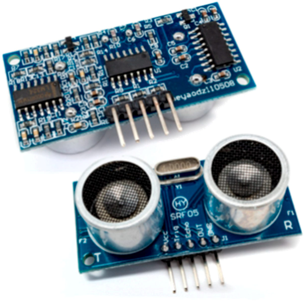
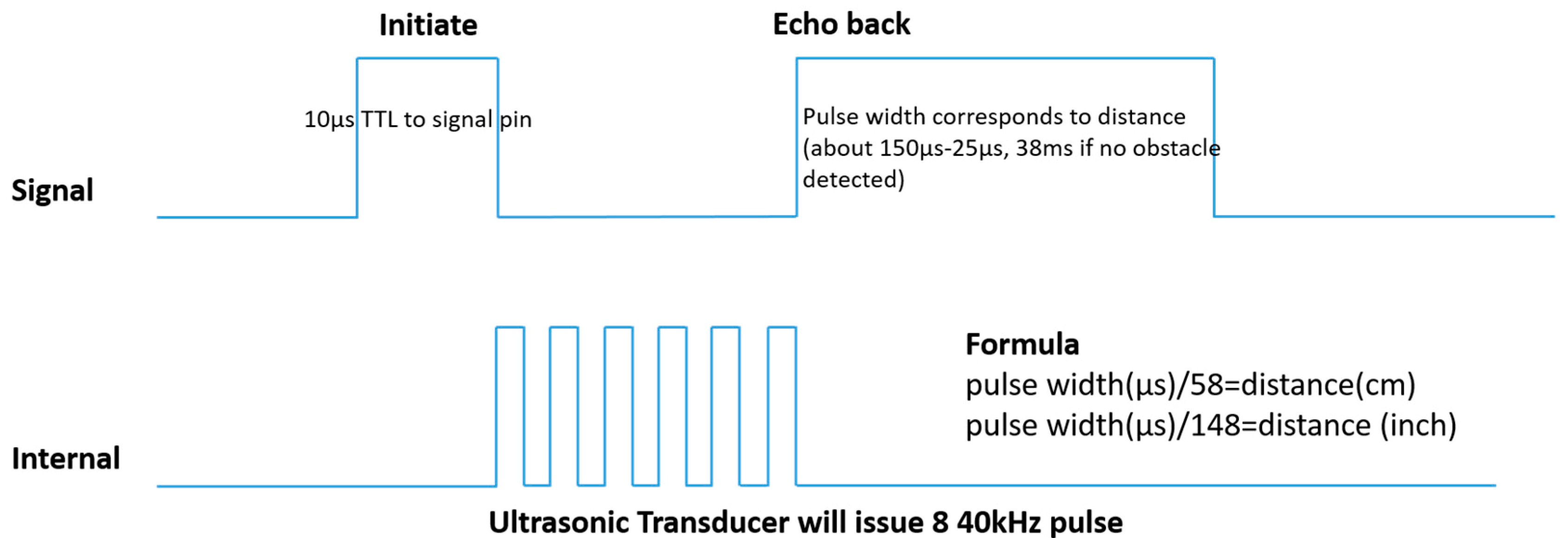
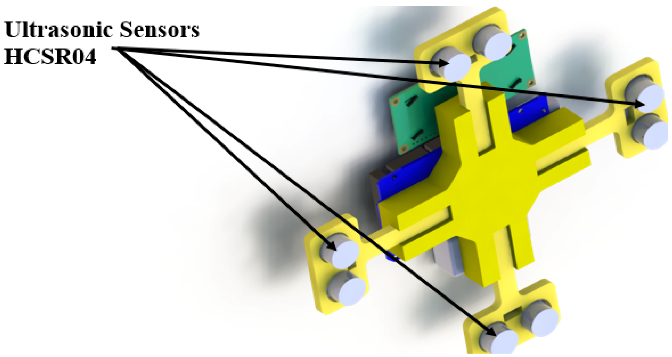
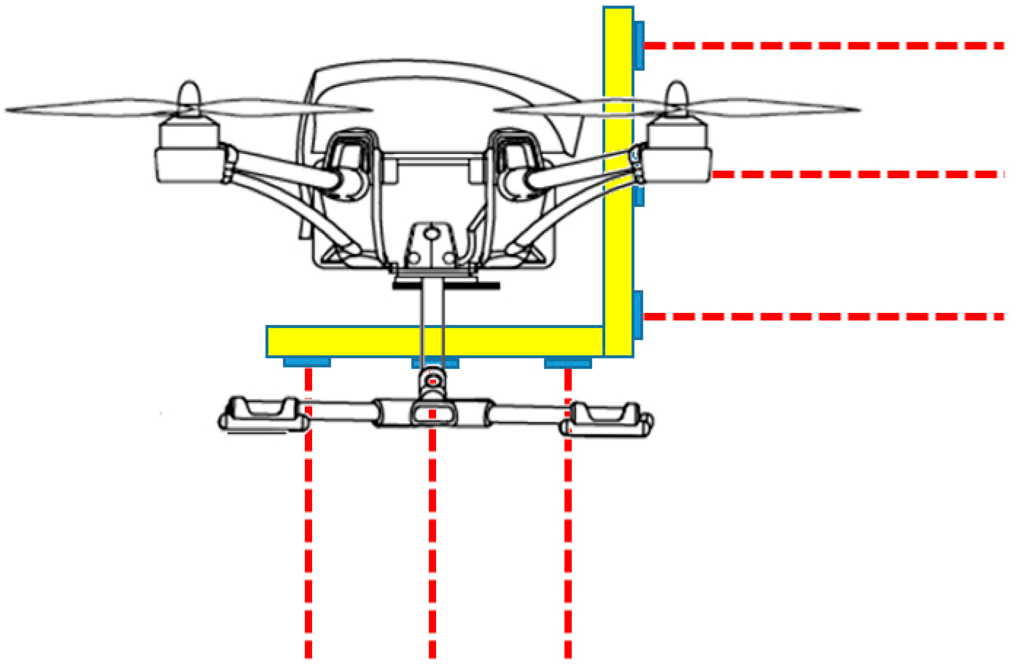
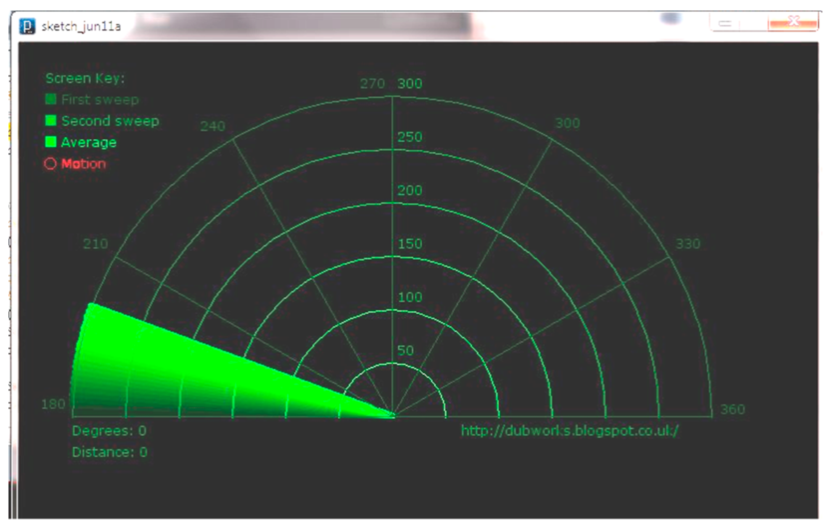
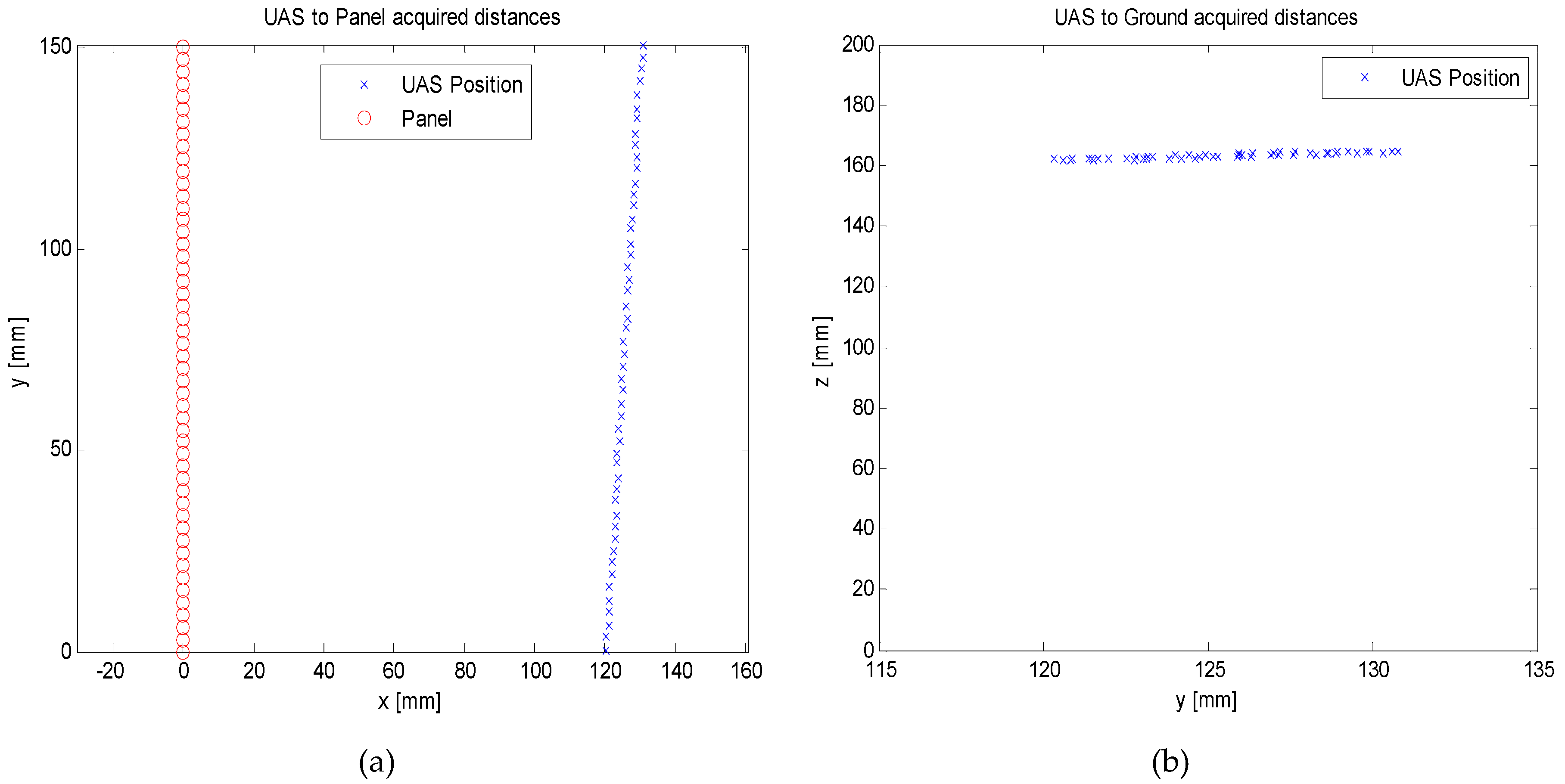
3.3. Ultrasonic Distance Keeper System (UDKS) and Data Filtering

Detecting and avoiding obstacles in the inspection area is a fundamental task for a safe, automatic GVI procedure. The system developed is based on a commercial off-the-shelf ultrasonic sensor, the HC-SR04, as shown in Figure 4 [39]. It provides distance measurements in the range of 2–400 cm with a target accuracy of 3 mm. These features guarantee a correct distance from the aircraft and other obstacles in the inspection area.
The module includes the ultrasonic transmitter and receiver and control circuitry. The shield has four pins (VCC and Ground for power supply, Echo and Trigger for initialization and distance acquisition). Technical specifications of the HC-SR04 are reported in Table 3.
To start measurements, the trigger pin of the sensor needs a high pulse (5V) for at least 10 μs, which initiates the sensor. Eight cycles of ultrasonic burst at 40 kHz are transmitted, and when the sensor detects ultrasonic echo returns, the Echo pin is set to High. The delay between the Trig pulse and the Echo pulse is proportional to the distance from the reflecting object. Figure 5 summarizes the ranging measurement sequence. If no obstacles are detected, the output pin will give a 38-ms-wide, high-level signal. For optimal performance, the surface of the object to be detected should be at least 0.5 square meters. Assuming a value of 340 m/s for the speed of sound, the distance (in centimeters) is given by the delay time divided by 58.
To improve measurement accuracy, the relationship between the speed of sound a and temperature and relative humidity variation has been considered:
a = γ   R   T
where γ is the heat capacity ratio (1.44 for air), R is the universal gas constant (287 J/kg K for air) and T is the temperature (K). A low-cost digital temperature and humidity sensor (DHT11) has been integrated in the sensor suite. The sensor provides a digital signal with 1-Hz sampling rate. The humidity readings are in the range of 20–80% with 5% accuracy, and the temperature readings are in the range 0–50 °C with ±2 °C accuracy [40]. The adjustment is performed during the acquisition of distance data by means of Arduino sketches and libraries for the management of sensors (DHT11 and HC-SR04) and for data collection. Experimental results and an analysis on the improved performance of the sonic ranging sensor were presented in previous works [41,42,43].
To obtain high reliability, a wider scanning area and accurate distance measurements, the designed UDKS employs four ultrasonic sensors [44] in a cross configuration (Figure 6 and Figure 7). The frame has been designed and realized by the authors with a 3D printer. The total weight (frame and sensors) is 78 g.
The microcontroller which acquires and manages measurements from the four-sensor structure is an Arduino Mega2560 board, powered by the LiPo battery of the MAV. The board acquires distance data from the sensors at 20-Hz sampling rate and sends the measurements to the PC-based ground station via a Wi-Fi link. The distance readings are corrected for temperature and humidity variations (see Equation. (1)) and are successively smoothed with a simple 1D Kalman filter.
The data acquisition system and the observation model are described by the following equations:
{ x k + 1 = A x k + w k y k = C x k + v k
where x k is the k-th distance; w k is the model noise, assumed as Gaussian with zero mean and variance Q, y k is the k-th measurement; v k is the measurement noise, assumed as Gaussian with zero mean and variance R (in our case, 0.09 cm2, as declared by the manufacturer, see Table 3). In our case, A and C are scalar quantities equal to 1. The Kalman filter algorithm is based on a predictor-corrector iterative sequence, as follows:
x ^ k + 1 | k = x ^ k | k   ( predicted   distance   value ,   before   measurement )
P k + 1 | k = P k | k + Q   ( a-priori   estimation   error )
K k + 1 = P k + 1 | k P k + 1 | k + R   ( Kalman   gain )
x ^ k + 1 | k + 1 = x ^ k + 1 | k + K k + 1 ( y k + 1 x ^ k + 1 | k )   ( new   estimate   from   current   measurement )
P k + 1 | k + 1 = P k + 1 | k ( 1 K k + 1 )   ( a-priori   estimation   error )
The implementation of Equations (4) to (7) in the Arduino IDE (Integrated Development Environment) is reported in Figure 8 as a function (kalmanSmooth) called whenever a new distance measurement (the variable Reading) is available from the sensors.
All data (raw distance measurements, smoothed distances, raw and processed images) received via the Wi-Fi link are stored in the PC-based ground station for analysis and further processing with Matlab. As an alternative, a LabVIEW VI (Virtual Instrument), developed by the authors, performs offline data processing (noise removal, calibration).
During the first experimental sessions, the UDKS has been positioned below the quadrotor. A complete UDKS will use a second cross configuration, like the one depicted in Figure 7, coupled to the lateral side of the UAV, to insure range detection when the quadrotor is flying over the fuselage and along the sides of the aircraft to be inspected. Figure 9 shows the assembly. The total payload weight slightly exceeds the limits imposed by the manufacturer, but by using wider blades (or, obviously, a greater quadrotor) the lift-off weight will increase. The complete configuration has not been tested and will be the object of future experimental campaigns.
Another idea to be developed is a real-time obstacle mapping system, obtained by coupling the SR sensor with a servomotor in a rotary configuration, as shown in Figure 10—a sort of ultrasonic radar which sends data to a PPI (Plan Position Indicator)-like screen provided by the Arduino IDE and allows the inspector to visually detect the presence of obstacles in the surroundings of the drone (Figure 11).

4. Experimental Results

This section shows some preliminary results of a test flight (in manual mode) of the MAV equipped with the GVI hardware (camera, UDKS, microcontroller) previously illustrated. The main objectives of this first flight test are to verify correct distance acquisition by the sensors and to evaluate the performance of the image-processing software. The inspected targets are different aircraft test panels damaged by hail and lightning strikes. The minimum distance considered for the GVI procedure is about 1.5–2 m from the aircraft and other obstacles in the area. The UAS flew in a cylindrical “safety area”, with the axis corresponding to the nominal inspection path to avoid collisions with the aircraft. The flight time, due to the high current absorption of the payload, was of the order of 5 min, about 50% of the nominal endurance as specified by the manufacturer.
According to Illuminating Engineering Society (IES), direct, focused lighting is the recommended general lighting for aircraft hangars [45]. Generally, most maintenance tasks require between 75 and 100 fc (foot-candles), i.e., 800-1100 lux (or lumen per square meter). The room in which the flight tests were performed is 10 × 6-m2, 4-m high, with high-reflectance walls and floor, helping in reflecting light and distributing it uniformly. The average measured brightness was 80 fc (860 lux). We arranged the experimental setup in order to obtain direct, focused lighting and minimize specular reflection from the test panels, avoiding glare. Compatibility with particular lighting conditions such as flashlight or drop-light, has not been tested.
As an example of the UDKS measurements, Figure 12 shows an acquisition at 1.20-m horizontal distance from the test panel and 1.60-m hovering height from the floor. Kalman filtering has been applied in real-time by the microcontroller to reduce measurement noise. A small drift (about 10 cm) can be noted during the movement of the craft along the direction of the test panel, due to the manual mode: In this initial test, no automatic path planning was implemented, and the UAS was piloted by a human operator located on the ground station a few meters away from the quadrotor.
Figure 13a shows the first test panel, with damage caused by hail. The HD camera acquired the image of the panel, and the embedded image-processing software module, run by the Raspberry Pi 2 computer board, sent the image to the ground control station highlighting the damaged areas (Figure 13b).
Figure 14a shows the second test item damaged by a lightning strike, which was simulated in a laboratory by inducing a current on the panel. The damaged area was correctly identified by the image-processing algorithms and is highlighted in Figure 14b.
From these preliminary tests, it can be deduced that automated damage detection, even in areas not easily reachable by a human inspector, allows us to significantly reduce the inspection time. Moreover, the remote operator can identify structural damages in real time and verify the correctness of the UAS flight path by analyzing the distance measurements provided by the UKDS.

5. Conclusions and Further Work

This paper has presented the conceptual design of an embedded system, useful for GVI in aircraft maintenance, installed on a commercial micro unmanned aircraft vehicle (MAV) and coupled to a remotely-operated PC-based ground station. The architecture of the ultrasonic distance keeper system (UDKS) and of the image acquisition subsystem have been presented and analyzed. The tools and processing used for this research were:
-
MAV (quadrotor);
-
Microprocessor and embedded HD camera (Raspberry);
-
Open-source image processing libraries;
-
Wi-Fi link for data transmission to a PC-based ground station;
-
SR sensors for distance measurements;
-
Microcontroller (Arduino) and IDE;
-
Matlab/LabVIEW for post-processing and data presentation.
The first tests have shown the correctness of the distance acquisition system (UDKS) and the capability of the HD camera, managed by a computer board with embedded image processing software, to identify damaged areas and send in real time images of the critical (damaged) zones to a remote operator in a ground control station, equipped with a laptop computer.
Future developments of the research activity are mainly focused on the full-field trajectory planning. During a GVI procedure, the UAS must be able to plan and follow a specific path, which mainly depends on the type and size of the aircraft to be inspected. Collecting top views of the aircraft will allow us to define a safe inspection trajectory, and to perform fully automatic inspection flights around the structure of the craft. Work is currently underway in defining algorithms for generating optimal paths that maximize the coverage of the aircraft structure [46]. Different path-planning algorithms will be tested, and the most promising, from preliminary studies, seems to be the Rapidly-exploring Random Tree (RRT) methodology [47].
Furthermore, different sensors are being evaluated and tested to increase the accuracy of distance measurements. Currently, experiments with a Lidar (Laser Detection and Ranging) are giving good results in terms of increased accuracy and reduced power consumption. Another issue to be dealt with in future work is the design of an effective automated Detect-And-Avoid (DAA) strategy, to ensure safe flight of the UAS and to eliminate possible collisions with obstacles in the flight path [48,49]. Other issues, such as increasing the endurance (flight time) with high-capacity LiPo batteries, or using a larger platform to accommodate different sensors, still remaining in the MAV category, are also under examination.

Author Contributions

Conceptualization, Software, U.P.; Methodology, Resources, Data Curation, U.P. and S.P.; Writing-Original Draft preparation, U.P.; Writing-Review& Editing, S.P.

Funding

This Research received no external fundings.

Conflicts of Interest

The authors declare no conflict of interest.

References

  1. Air Transport Association of America Inc. ATA MSG-3, Operator/Manufacturer Scheduled Maintenance Development, Vol. 1- Fixed Wing Aircraft; ATA: Washington, DC, USA, 2015. [Google Scholar]
  2. Intergraph Corp. Maintenance Steering Group-3 (MSG-3)-Based Maintenance and Performance-Based Planning and Logistic (PBP&L) Programs—A White Paper; Intergraph Corporation: Madison, AL, USA, 2006. [Google Scholar]
  3. US Department of Transportation—FAA. Visual Inspection for Aircraft; Advisory Circular (AC) No. 43-204; Federal Aviation Administration: Washington, DC, USA, 1997.
  4. Airbus. Innovation Takes Aircraft Visual Inspection to New Heights. 2018. Available online: https://www.airbus.com/newsroom/news/en/2018/04/innovation-takes-aircraft-visual-inspections-to-new-heights.html (accessed on 13 October 2018).
  5. Office of the Secretary of Defense. Unmanned Aircraft Systems Roadmap: 2005–2030; Office of the Secretary of Defense: Washington, DC, USA, 2005.
  6. Morgenthal, G.; Hallermann, N. Quality Assessment of Unmanned Aerial Vehicle (UAV) Based Inspection of Structures. Adv. Struct. Eng. 2014, 17, 289–302. [Google Scholar] [CrossRef]
  7. Marinho, C.A.; de Souza, C.; Motomura, T.; Gonçalves da Silva, A. In-Service Flares Inspection by Unmanned Aerial Vehicles (UAVs). In Proceedings of the 18th World Conference on Nondestructive Testing, Durban, Africa, 16–20 April 2012. [Google Scholar]
  8. Sadovnychiy, S. Unmanned Aerial Vehicle System for Pipeline Inspection. In Proceedings of the 8th WSEAS International Conference on Systems, Athens, Greece, 12–14 July 2004. [Google Scholar]
  9. Tatum, M.C.; Liu, J. Unmanned Aerial Vehicles in the Construction Indstry. In Proceedings of the 53rd ASC Annual International Conference, Seattle, WA, USA, 5–8 April 2017; pp. 383–393. [Google Scholar]
  10. Metni, N.; Hamel, T. A UAV for bridge inspection: Visual servoing control law with orientation limits. Autom. Constr. 2007, 17, 3–10. [Google Scholar] [CrossRef]
  11. Eschmann, C.; Kuo, C.-M.; Kuo, C.-H.; Boller, C. Unmanned Aircraft Systems for Remote Building Inspection and Monitoring. In Proceedings of the 6th European Workshop on Structural Health Monitoring (EWSHM 2012), Dresden, Germany, 3–6 July 2012. [Google Scholar]
  12. Zhang, C. An UAV-based photogrammetric mapping system for road condition assessment. Remote. Sens. Spat. Inf. Sci. 2008, 37, 627–632. [Google Scholar]
  13. Leonardi, G.; Barrile, V.; Palamara, R.; Suraci, F.; Candela, G. 3D Mapping of Pavement Distresses Using an Unmanned Aerial Vehicle (UAV) System; Springer: Berlin, Germany, 2018; Volume 101, pp. 164–171. [Google Scholar]
  14. Montambault, S.; Beaudry, J.; Touissant, K.; Pouliot, N. On the application of VTOL UAVs to the inspection of Power Utility Assets. In Proceedings of the 1st International Conference on Applied Robotics for the Power Industry (CARPI 2010), Montreal, QC, Canada, 5–7 October 2010; pp. 1–7. [Google Scholar]
  15. Deng, C.; Wang, S.; Huang, Z.; Tam, Z.; Liu, J. Unmanned Aerial Vehicles for Power Line Inspection: A Cooperative Way in Platforms and Communications. J. Commun. 2014, 9, 687–692. [Google Scholar] [CrossRef]
  16. Bellezza Quarter, P.; Grimaccia, F.; Leva, S.; Mussetta, M.; Aghaei, M. Light Unmanned Aerial Vehicles (UAVs) for Cooperative Inspection of PV Plants. IEEE J. Photovolt. 2014, 4, 1107–1113. [Google Scholar] [Green Version]
  17. Kim, H.; Sim, S.H.; Cho, S. Unmanned Aerial Vehicle (UAV)-powered Concrete Crack Detection based on Digital Image Processing. In Proceedings of the 6th International Conference on Advances in Experimental Structural Engineering, Urbana-Champaign, IL, USA, 1–2 August 2015. [Google Scholar]
  18. Rodrigues Santos de Melo, R.; Bastos Costa, D.; Sampaio Alvares, J.; Irizarri, J. Applicability of unmanned aerial system (UAS) for safety inspection on construction sites. Safety Sci. 2015, 98, 174–185. [Google Scholar] [CrossRef]
  19. Kit, H.T.; Chen, H. Autonomous Elevator Inspection with Unmanned Aerial Vehicle. In Proceedings of the 3rd Asia-Pacific World Congress on Computer Science and Engineering (APWC on CSE), Nadi, Fiji, 5–6 December 2016. [Google Scholar]
  20. Ellenberg, A.; Branco, L.; Krick, A.; Baroli, I.; Kontsos, A. Use of Unmanned Aerial Vehicle for Quantitative Infrastructure Evaluation. J. Infrastruct. Syst. 2014, 21. [Google Scholar] [CrossRef]
  21. Blumenthal, S.; Holz, D.; Linder, T.; Molitor, P.; Surmann, H.; Tretyakov, V. Teleoperated Visual Inspection and Surveillance with Unmanned Ground and Aerial Vehicles. In Proceedings of the REV2008—Remote Engineering & Virtual Instrumentation, Düsseldorf, Germany, 23–25 June 2008. [Google Scholar]
  22. See, J.E. Visual Inspection: A Review of the Literature; SANDIA Report SAND2012-8590; Sandia National Laboratories: Albuquerque, NM, USA, 2012; p. 77.
  23. Eisenbeiss, H. A Mini Unmanned Aerial Vehicle (UAV): System Overview and Image Acquisition. Remote Sens. Spat. Inf. Sci. 2004, 36.5/W1, 1–7. [Google Scholar]
  24. Dalamagkidis, K. Classification of UAVs. In Handbook of Unmanned Aerial Vehicles; Springer Science+Business Media: Dordrecht, The Netherlands, 2015; pp. 83–91. [Google Scholar]
  25. Valavanis, K.P. Introduction. In Advances in Unmanned Aerial Vehicles. State of the Art and the Road to Autonomy; Springer: Dordrecht, The Netherlands, 2007; pp. 3–13. [Google Scholar]
  26. Bouabdallah, S.; Siegwart, R. Design and Control of a Miniature Quadrotor. In Advances in Unmanned Aerial Vehicles. State of the Art and the Road to Autonomy; Valavanis, Springer: Dordrecht, The Netherlands, 2007; pp. 171–210. [Google Scholar]
  27. Schmidt, M.D. Simulation and Control od a Quadrotor Unmanned Aerial Vehicle. Ph.D. Thesis, College of Engineering, University of Kentucky, Lexington, Kentucky, 2011. [Google Scholar]
  28. Nonami, K. Autonomous Flying Robots: Unmanned Aerial Vehicles and Micro Aerial Vehicles; Springer: Heidelberg, Germany, 2010. [Google Scholar]
  29. Dief, T.N.; Yoshida, S. Review: Modeling and Classical Controller of Quad-rotor. IRACST Int. J. Comput. Sci. Inf. Tecnol. Secur. 2015, 5, 314–319. [Google Scholar]
  30. Hoffmann, G.; Huang, H.; Waslander, S.L.; Tomlin, C.J. Quadrtor Helicopter Flight Dynamics and Control: Theory and Experiment. In Proceedings of the AIAA Guidance, Navigation and Control Conference and Exhibit, AIAA 2007-6461, Hilton Head, CA, USA, 20–23 August 2007. [Google Scholar]
  31. CEI (Conrad Electronic International). RC Logger® EYE One Xtreme—Operating Instructions (88008RC—Mode 2); CEI Ltd.: Hong Kong, China, 2015; p. 60. [Google Scholar]
  32. Raspberry Pi Foundation. Raspberry Pi Camera Module v2. Hardware Specification. 2015. Available online: https://www.raspberrypi.org/documentation/hardware/camera/ (accessed on 13 October 2018).
  33. Raspberry Pi Foundation. Raspberry Pi 2 Model B Specifications. 2015. Available online: https://www.raspberrypi.org/products/raspberry-pi-2-model-b/ (accessed on 13 October 2018).
  34. Brown, D.C. Close-range camera calibration. Photogramm. Eng. 1971, 37, 855–866. [Google Scholar]
  35. Del Pizzo, S.; Papa, U.; Gaglione, S.; Troisi, S.; Del Core, G. A Vision-based navigation system for landing procedure. Acta IMEKO 2018, 7, 102–109. [Google Scholar] [CrossRef]
  36. Hough, P.V.C. Method and Means for Recognizing Complex Patterns. US Patent Office No. US 3069654, 18 December 1962. [Google Scholar]
  37. Canny, J. A computational approach to edge detection. IEEE Trans. Pattern Anal. Mach. Intell. 1986, 6, 679–698. [Google Scholar] [CrossRef]
  38. Luhman, T.; Robson, S.; Kyle, S.; Harley, I. Close Range Photogrammetry: Principles, Techniques and Applications; Whittles Publishing/John Wiley & Sons, Inc.: Hoboken, NJ, USA, 2006. [Google Scholar]
  39. Cytron Technologies. HC-SR04 Ultrasonic Sensor—Product User’s Manual, V 1.0; Cytron Technologies Sdn. Bhd.: Penang, Malaysia, 2013. [Google Scholar]
  40. Adafruit Industries. Adafruit Learning System—DHT11, DHT12 and AM2302 Sensors. Available online: https://cdn-learn.adafruit.com/downloads/pdf/dht.pdf?timestamp=1543644105 (accessed on 13 October 2018).
  41. Papa, U.; Picariello, F.; Del Core, G. Atmosphere Effect on Sonar Sensor System. Aerosp. Electron. Syst. Mag. 2016, 31, 34–40. [Google Scholar] [CrossRef]
  42. Papa, U.; Del Core, G. Design of Sonar Sensor Model for Safe Landing of an UAV. In Proceedings of the 2nd IEEE Workshop on Metrology for Aerospace, Benevento, Italy, 3–5 June 2015; pp. 361–365. [Google Scholar]
  43. Papa, U.; Ponte, S.; Del Core, G.; Giordano, G. Obstacle Detection and Ranging Sensor Integration for a Small Unmanned Aircraft System. In Proceedings of the 4th International Workshop on Metrology for Aerospace (MetroAeroSpace), Padova, Italy, 21–23 June 2017. [Google Scholar]
  44. Hamel, T.; Mahony, R. Visual servoing of under-actuated dynamic rigid body system: An image space approach. IEEE Trans. Robot. Autom. 2002, 18, 187–198. [Google Scholar] [CrossRef]
  45. DiLaura, D.L.; Houser, K.W.; Mistrick, R.G.; Stelly, G.R. The Lighting Handbook, 10th ed.; Illuminating Engineering Society (IES): New York, NY, USA, 2011. [Google Scholar]
  46. Almadhound, R.; Taha, T.; Seneviratne, L.; Dias, J.; Cai, G. Aircraft Inspection Using Unmanned Aerial Vehicles. In Proceedings of the International Micro Air Vehicle Conference and Competition 2016 (IMAV 2016), Beijng, China, 17–21 October 2016. [Google Scholar]
  47. Bry, A.; Roy, N. Rapidly-exploring Random Belief Trees for Motion Planning Under Uncertainty. In Proceedings of the IEEE Intenational Conference on Robotics and Automation (ICRA 2011), Shangai, China, 9–13 May 2011. [Google Scholar]
  48. Griffiths, S.; Saunders, J.; Curtis, A.; Barber, B.; McLain, T.; Beard, R. Obstacle and Terrain Avoidance for Miniature Aerial Vehicles. In Advances in Unmanned Aerial Vehicles. State of the Art and the Road to Autonomy; Springer: Dordrecht, The Netherlands, 2007; pp. 213–244. [Google Scholar]
  49. Papa, U. Embedded Platforms for UAS Landing Path and Obstacle Detection; Book Series of Studies in Systems, Decision and Control; Springer International Publishing: Dordrecht, The Netherlands, 2018; Volume 136. [Google Scholar]
Figure 1. Aspect (a) and dimensions (b) of the RC EYE One Xtreme (Mode 2).
Electronics 07 00435 g001
Figure 2. Image acquisition subsystem (Raspberry Pi 2 Model B and Pi camera), standalone configuration.
Electronics 07 00435 g002
Figure 3. Image acquisition subsystem mounted on RC EYE One Xtreme.
Electronics 07 00435 g003
Figure 4. HC-SR04 sonic ranging sensor.
Electronics 07 00435 g004
Figure 5. Sonic Ranger sequence chart.
Electronics 07 00435 g005
Figure 6. Rendering of the UDKS frame.
Electronics 07 00435 g006
Figure 7. UDKS mounted on the UAV.
Electronics 07 00435 g007
Figure 8. Arduino function kalmanSmooth for Kalman filtering of distance data acquired by the SR sensor. P, Q and R are the variances of the smoothing error, of the measurement model and of the acquired measurement, respectively.
Electronics 07 00435 g008
Figure 9. UDKS installation, configuration in front of and below the quad rotor.
Electronics 07 00435 g009
Figure 10. Rotary/radar configuration.
Electronics 07 00435 g010
Figure 11. Real-time distance mapping and manual obstacle detection through the embedded Arduino IDE.
Electronics 07 00435 g011
Figure 12. (a) Acquired distance from the damaged panel; (b) distance from the ground.
Electronics 07 00435 g012
Figure 13. (a) Test panel (aluminum) damaged by hail. (b) Image of the test panel with the hail-strike damage highlighted. The image processing module has also identified another defective area (small rectangle on the right) not damaged by hail.
Electronics 07 00435 g013
Figure 14. (a) Lightning-strike damage on an aluminum panel. (b) Image of the damaged area highlighted. A circular pattern has been correctly identified by the CHT routine and is enclosed in the small rectangle on the right side of the image.
Electronics 07 00435 g014
Table 1. UAV categorization (adapted from References [23,24]).
Mass (kg)Range (km)Altitude (m)Endurance (h)
Micro UAV (MAV)<5<10Up to 250≤1
Mini UAV<20 or 25<10Up to 300<2
Low Altitude, Long Endurance (LALE)15–25>5003000>24
Low Altitude, Deep Penetration (LADP)250–2500>25050–90000.5–1
Medium Altitude, Long Endurance (MALE)1000–1500>500300024–48
High Altitude, Long Endurance (HALE)2500–5000>20002000024–48
Tactical UAV (TUAV), Close Range (CR)25–15010–3030002–4
TUAV, Medium Range (MR)150–500>500800010–18
Table 2. Raspberry Pi Camera Module (v2) hardware specification.
FeaturesProperties
Size, weight25 × 24 × 9 mm, 3 g
Still resolution8 Megapixels
Video modes1080p30, 720p60 and 640 × 480p60/90
Sensor resolution3280 × 2464 pixel (Sony IMX219)
Focal length3.04 mm
Pixel size1.12 × 1.12 μm
Sensor sizeWidth: 6.004 ± 0.006 mm
Height: 3.375 ± 0.005 mm
Fixed focus1m to infinity
Frame ratemax 90 fps
Horizontal/Vertical FOV (Field Of View)62.2/48.8 degrees
Table 3. HC-SR04 technical specifications.
HC-SR04
Supply Voltage+5 V DC
Working Current15 mA
Ranging distance2–400 cm
Range resolution0.3 cm
Input Trigger10-μs TTL pulse
Echo pulsePos. TTL pulse
Burst Frequency40 kHz
Measuring Angle30 degrees
Weight20 g
Dimensions45 × 20 × 15 mm

