1. Introduction
The implementation of digital signal processing (DSP) methods is effective in many practical applications, e.g., noise-resistive data processing system with high precision and resolution, easy subsystems connection, the stabilization of data processing channel etc. [
1,
2,
3].
The development of DSP applications triggered many studies in a field of creating specialized DSP devices with maximal efficiency. To solve this problem, the parallel pipeline computing was introduced. This approach allowed the performing of real-time DSP tasks.
Most of the DSP tasks consider large amount of computations over the big data arrays. The increased speed of DSP calculations can be achieved through the introduction of new mathematics, based on non-positional modular codes. This paper shows the efficiency of executing DSP methods and algorithms based on ring and field algebraic structures, e.g., Residue Number System (RNS).
Common drawbacks of real-time data processing techniques caused the expansion of application areas of modular arithmetic. The analysis gives the following groups of applications for non-positional modular codes.
The first group includes traditional DSP approaches based on orthogonal signal transforms in a complex numbers field [
4,
5,
6,
7,
8,
9]. Parallel data processing through the computational channels, determined by RNS basis, and the low bit depth of residues allows to increase the processing speed. One paper [
10] presented the algorithm for navigational data post-processing, allowing a decrease of positioning errors through the multiple measurement of pseudo-range in the chosen constellation of satellites. To post-process the signals in real-time the Katkov et al. proposed parallel computations in RNS. The implementation of the RNS approach allowed an increase in the number of measurements, which gave the desired reduction in positioning errors.
The second group includes the methods and algorithms of digital filtering based on residue number codes. Multiple studies [
11,
12,
13] have described the methods for constructing non-positional digital filters that are based on algebraic structures, possessing the properties of ring and field.
In [
7,
13,
14], Omondi et al. have shown that the digital filtering is one of the most promising applications of the finite residue field algebra, which allows overcoming the main drawback of digital filters (DF), namely, the inability to process high-frequency signals whose bandwidth is limited by the Nyquist frequency [
15]. Therefore, for the high-frequency signals the analog filters were used or decimation of the processed signal was carried out. Thus, the problems of filter efficiency estimation have not been studied as intensively and the criteria for the applicability of filters based on the algebra of finite residue fields have not been developed. In addition, the structures of modular filters have been not described in detail, and there are no experimental data about their performance in various signal processing applications. From a practical point of view, the creation of DF based on the algebra of finite residue fields that allow processing of the high frequency signals will reduce application of power consumptive and hard-to-design analog filters.
Additional signal transformation, which is necessary for processing input samples of the DF during the sampling period, leads to additional distortions and a decrease of performance.
The calculation of one sample of the DF at the sampling frequency of 1 MHz is 6.08 μs for DSP processor TMS320C54. In this case, the sampling interval is approximately six times shorter than the time for calculating the output sample. When a sampling frequency is higher than the specified one, the sampling interval decreases and, consequently, the input sample cannot be processed in real time.
Let us show the comparative evaluation of the time on a certain DSP platform that is required for calculating the output sample of the positional DF and the filter implemented in the algebra of the finite residue field. The results of the evaluation are presented in
Table 1.
The comparative evaluation was carried out for the algorithm of the non-recursive filter implemented in the algebra of the finite field under the modular (tabular) execution of its basic operation. The basic operation time was selected as 2 ns (the time of reading data from the fast-acting memory device was 0.1–4 ns [
16]), while the output sample was calculated in parallel pipeline mode, i.e., in one clock cycle of the processor.
The evaluation of time taken to calculate the output sample of the DF shows the advantages of the algebra of the finite residue field over the positional numeral system.
In
Section 2, implementation of modular digital non-recursive filters are introduced. In
Section 3, an example of the estimation of the accuracy of calculating the output sample of the modular DF, which processes 16-bit input data and has 16-bit coefficients, has shown the correctness of the operation of the digital filtering algorithm implemented in the algebra of the finite residue field. In
Section 4, a brief discussion is given. In
Section 5, conclusions are made and the obtained results of calculations and simulation are presented.
2. Materials and Methods
The calculation of the output sample in a separate unit of the modular digital filter reads in the form [
12]
According to Equation (1), the coefficients
bi and the input samples
x(
nT − kT) of the filter must be represented by the numbers of the residue class. In this case, both the coefficients and the input samples of the filter are values belonging to the set of reminder values for the selected modulus
in accordance with Equations (2) and (3), the value of the intermediate sample of the filter will also belong to the following range of values:
The sequence of arithmetic operations required to calculate the output sample of the filter, in accordance with the difference equation [
17], is a chain of basic operations over the low-bit quantities (reminders)
αi, described by Equation (4)
where
Fi(
αi) is the integer residue function of
αi modulo
p; 3 ≤
l ≤ n.
The choice of the form of the base system of the finite residue ring algebra was determined by the nature of the problem being solved and was given in [
9,
12,
13,
14]. For the considered problem it was important to not simply justify the method of the base system selection, but also to determine the optimal structure for the developed DF.
The mathematical model for calculating intermediate samples in the
i-th unit of the modular DF in a given range can be written as:
Then, one can obtain a mathematical model for calculating the output sample of the
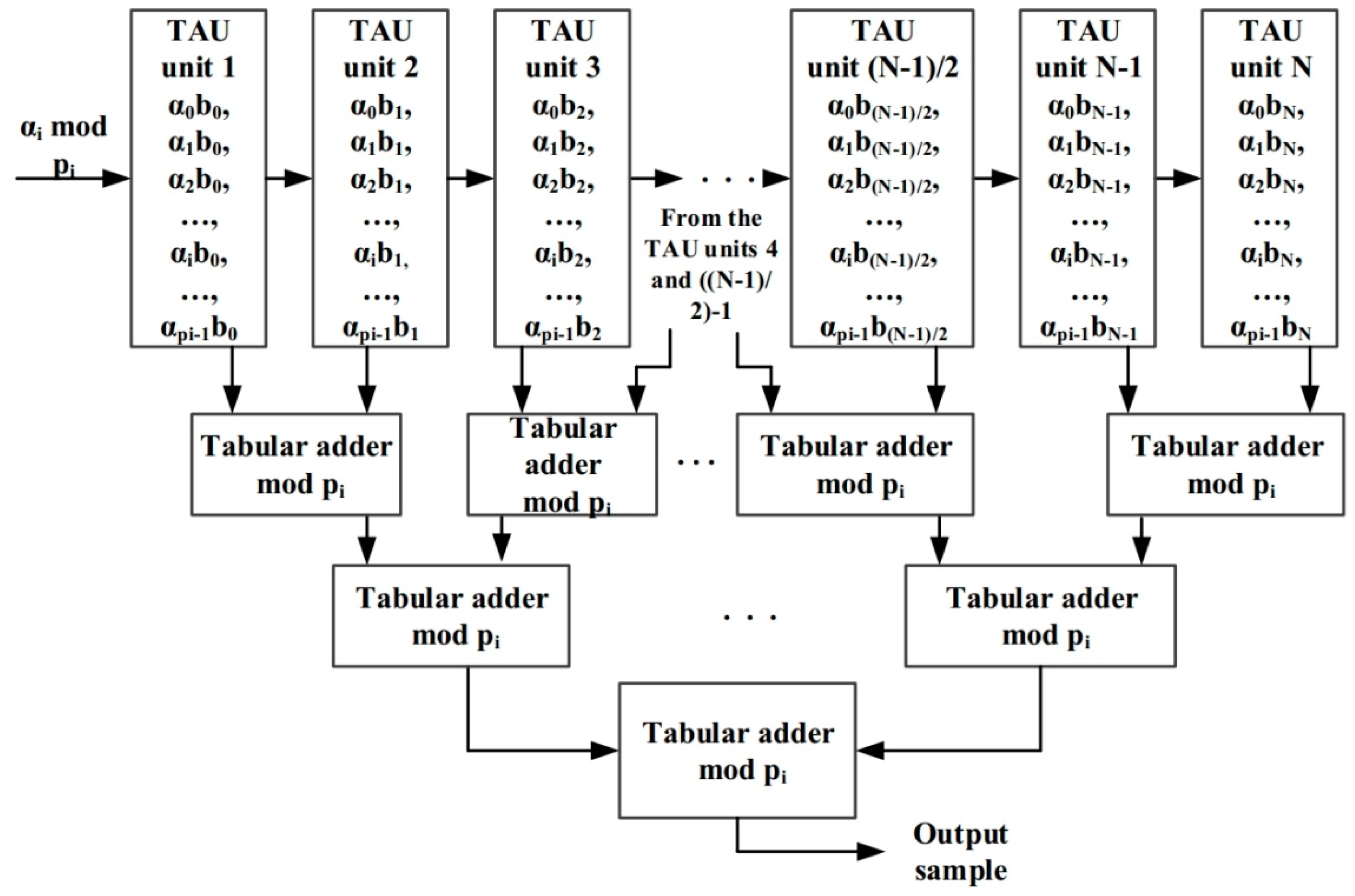
N-th order DF in a given range, taking into account the organization of parallel pipeline calculations in the form
where:
is the value of the intermediate sample calculated in the first two stages of the computational channel of the filter modulo
p1;
is the value of the intermediate sample calculated in the i − 1 and the i-th stages of the computational channel of the filter modulo p1;
is the value of the intermediate reading calculated in the penult and the last stages of the computational channel of the filter modulo p1; and
is the value of the intermediate sample calculated in the first two stages, in the i − 1 and the i-th stages, in the penultimate and the last stages of the computational channel of the filter modulo p2 …pn.
The structure of the DF based on the finite residue field algebra is shown in
Figure 1.
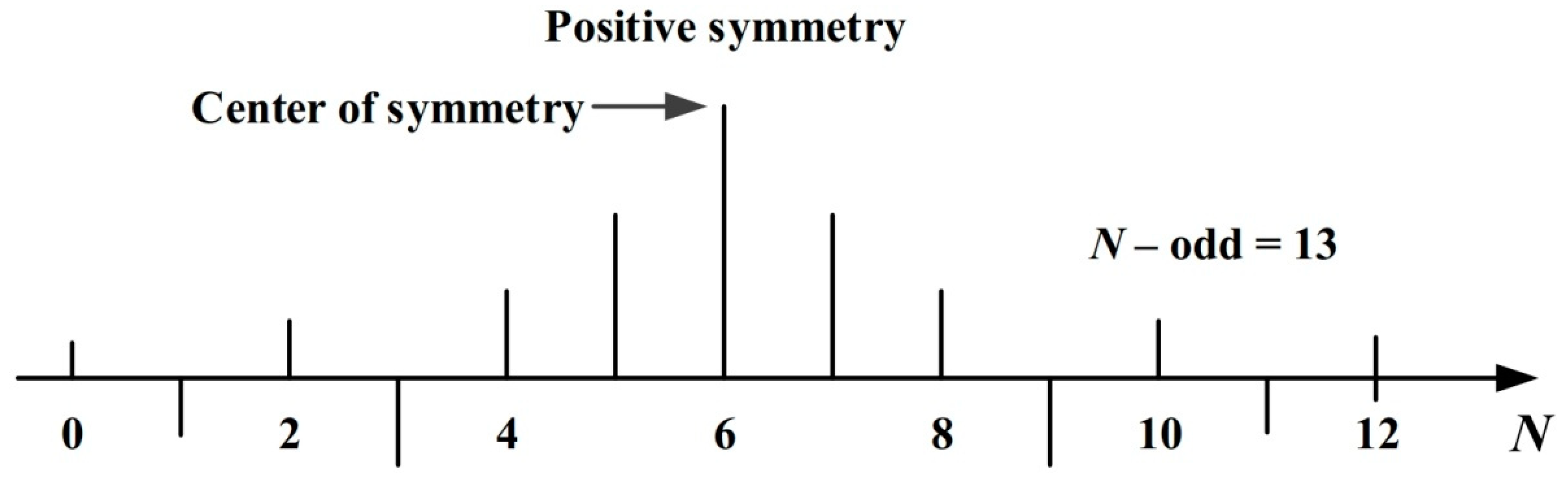
Let us consider a non-recursive DF with a symmetric impulse response (positive symmetry). An example of a symmetric impulse response for a filter of the 13th order is shown in
Figure 2. A feature of the DF with symmetric characteristic is that its samples symmetrically take values equal in magnitude and sign [
18].
Therefore, the filter coefficients for the
N-th order filter are defined as
The coefficient
defines the center of symmetry of the impulse response of the filter and will be used only once. Using the property of cyclicity of reminders and the filter coefficients
bi modulo
pi:additionally taking into account the fact that the values of the coefficients do not change during the algorithm execution, it is possible to represent the values of the intermediate samples for the coefficients
b0 and
bN−1 in the form given in
Table 2.
In
Table 2,
αi is the value of the remainder modulo and
p and
bi are the filter coefficients. One can obtain the tables similar to
Table 1 for the coefficients
. For the coefficient
, there is a separate table for performing the basic operation of a non-recursive DF. Thus, the number of tables
will be determined by the value
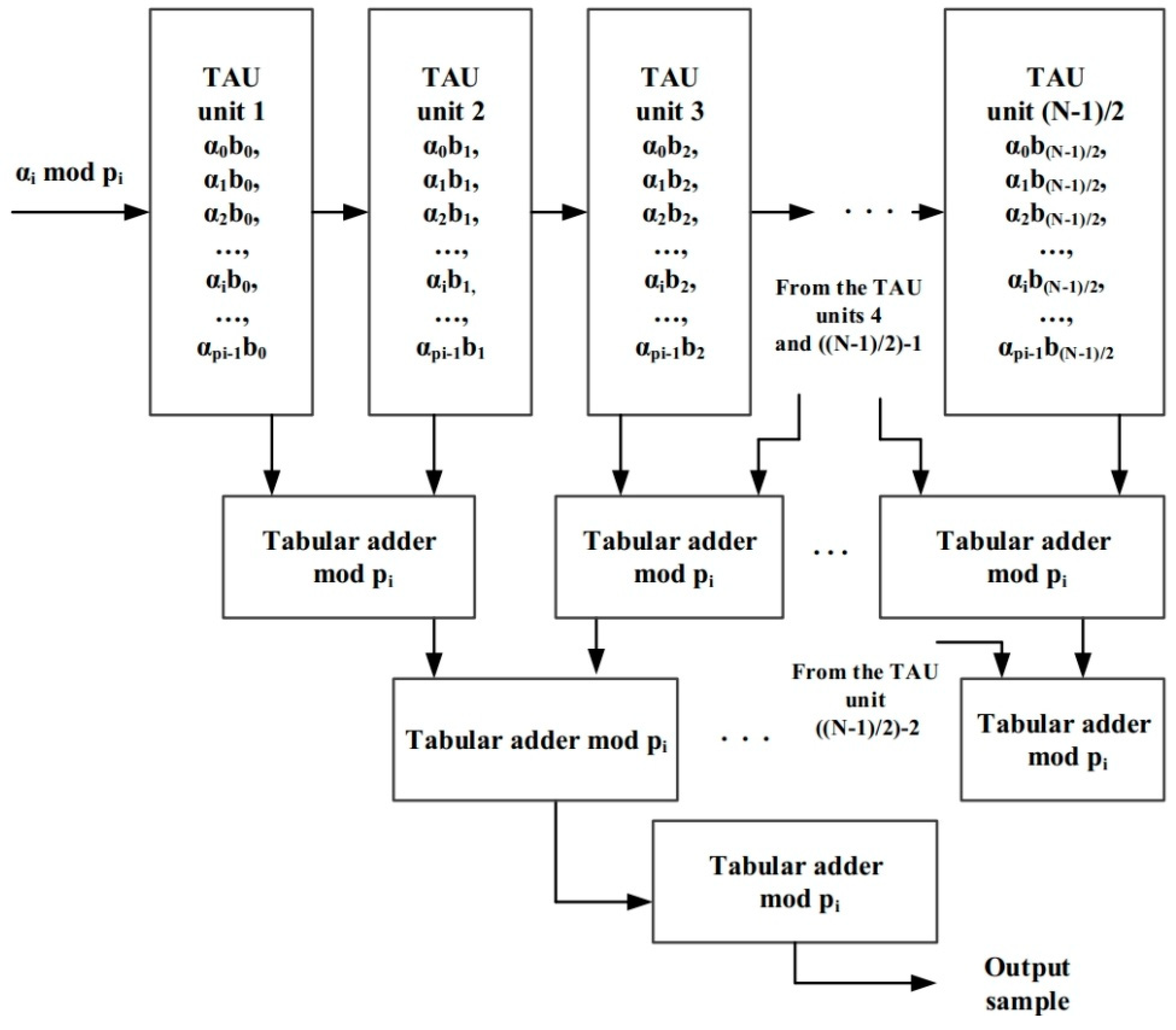
It is possible to construct a modified structure of the modular DF where the calculation of the output sample of the DF can be achieved using only
units, which is a major advantage over the filter shown in
Figure 1. The modified structure requires 1.94 times less hardware costs to implement the computing system modulo
pi, while the parameters of the filter quality do not change. For example, for a filter with a pulse characteristic length
N1 = 64, its modified structure will have a pulse characteristic length of
Nм = 33,
N1/
Nм = 1.94. The structure of the modified DF based on the algebra of the finite residue field is shown in
Figure 3.
Equation (6) can be re-written in the form:
where:
Table 3 represents an estimation of the hardware costs required to implement the DF structures shown in
Figure 1 and
Figure 3, depending on the order of DF. Generally, data on the DF input comes from an analog-to-digital converter and have a bit width of 8–16 bits depending on the speed and accuracy requirements of calculations. Thus, in the traditional implementation based on the DF structures shown in
Figure 1 and
Figure 3, the standard digital elements will be utilized, having a bit width of 8–16 bits.
Let us consider the processing of the 16-bit filter input samples. The data range will be from 0 to 65,535, and we can select a base system of the form:
where the range of the representation in the finite residue field is equal to
. To represent the reminders for the selected bases, five digits are required (
p1 = 9;
p2 = 17;
p3 = 19,
p4 = 23).
The required amount of memory for storing the values of the intermediate samples (
Table 2) and for tree tabular adder of the 32nd order modular modified DF (
Table 3) can be calculated as shown in
Table 4.
The experimental evaluation was carried out as follows. As an example, we took the elements of the modified modular DF of order 32 from
Table 3. For its implementation in a direct form, the typical implementation form of a FIR filter, one needs 17 tabular adders and 17 tabular multipliers. A tabular adder is a memory device that records the results of a modular addition operation of two residues for a particular modulus. Thus, for the modulus
p1 = 9, an 81-cell memory is required, where a 4-bit remainder is written in each cell. For 17 tabular adders, the total amount of required memory is 5508 bits = 81 × 4 × 17.
In fact, the tabular multiplier represents a unit of the modular DF, and according to
Table 2, the ROM coefficients and amount of memory needed for delay elements are taken into account as the hardware costs of the tabular multipliers.
The analysis has shown that in order to provide the calculation of the output sample for one modular clock cycle of the modular computational channel (the mode of parallel pipeline calculations), it is most expedient to use the adder of a tree structure.
The investigations carried out made it possible to reveal the important feature of the algebra of the finite field, namely, its natural redundancy. Since currently there is no universal element base for computational structures operating on the basis of finite field algebra, computations were performed on typical digital elements (registers, high-speed storage devices etc.).
With the application of typical digital devices, their bit capacity is equal to 16 bits for a chosen example. Therefore, the bit grid of typical digital elements was used on 33.3%, in accordance with Equation (7). Thus, the natural redundancy was inferred from the fact that for data processing it is sufficient to use only a part of the digital grid of the device, and the remaining, large enough part of it can be utilized to optimize the structure or to perform some other procedures of finite field algebra.
Figure 1 and
Figure 3 show that the modular DF was constructed on the basis of tabular adders and tabular arithmetic blocks that represent memory devices. In order to calculate the output sample of the DF on four bases (see the example above), four computational channels were required.
When calculating the intermediate samples in the filter units, it is possible to use one digital element for two bases simultaneously. For example, if a register is used, then two values of the reminders on two bases are written in its grid, and when they are transferred to a tabular arithmetic device, the bits of the reminders can be read in parallel. Thus, when we use typical digital elements, e.g., registers for storing intermediate 16-bit results, the modulus p1 = 9 provides processing with the reminders {0, 1, 2, 3, 4, 5, 6, 7, 8} represented by 3–4 binary digits. Hence, we can write two numbers represented by 3–4 binary digits in one register. Note that these numbers can be reminders of different moduli.
Therefore, the total hardware (memory) costs can be reduced twice and will be modulo p1 5,4 KB; modulo p2 24 KB; modulo p3 30 KB; and modulo p4 44 KB in our example case.
A feature of modular tabular arithmetic devices is that they are symmetric [
9,
14] consequently, one modular tabular arithmetic unit possessed a 100% memory reserve. Let us consider a tabular multiplier modulo 5 (
Table 5).
As one can see from
Table 5, the tabular multiplier modulo 5 is symmetric with respect to the left diagonal of the table: therefore, we used only half of it during the calculations. The second half can be utilized either as a reserve or for writing an intermediate result of calculations for another modulus, which also reduces hardware costs.
It should be noted that the width of the input filter samples determines the number and magnitude of the bases of the finite field algebra and their accuracy in processing in positional computing structures. Accordingly, the accuracy of the representation of the DF input samples and coefficients determines the accuracy of the calculation of the output samples, and the accuracy of the representation of the filter coefficients also determines its frequency response and, as a consequence, its selectivity.
3. Results
Let us illustrate the influence of the accuracy of the filter coefficients representation to its frequency response. As an example, we chose a 15th order DF with the impulse response given in
Table 6.
Table 7 shows the impulse response of the modular DF for the modulus
p = 5.
The obtained frequency responses (FR) are shown in
Figure 4.
One can see from
Figure 4 that the selectivity of the DF with the representation of its coefficients in the algebra of the finite ring overwhelms the selectivity of the positional filters. This can be explained by the fact that the filter coefficients in the algebra of the finite field can be represented with any given accuracy (see
Table 5 and
Table 6).
Let us estimate the accuracy of calculating the output sample of a modular DF that processes 16-bit input data and has 16-bit coefficients. The range of input data will be
. In order to satisfy the condition
(RNS—Residue Number System [
7] for modular DF) the following system of bases
was chosen.
When the multiplication operation is performed in the computational channel of the modular DF, the result must be in 32-bit length, since the rounding or truncation operation cannot be applied due to the fact that the intermediate result, represented in the modular code in each computational channel, will change. Therefore, an incorrect value of the filter output will be obtained. To consider this, we need to select of an expanded system of bases:
Then, the extended base system takes the form:
In this case, the structure of the DF computing device will include 10 computational channels with modulo . The modulus p9 = 31 was introduced with purpose to prevent overflow. Since the impulse response of the DF has negative coefficients, their representation in the modular code was carried out in the second half of the range (numbers from 32,768 to 65,535). The input data and the coefficients of the DF, having a positive sign, were represented in the first interval in the range from 0 to 32,767. The value of the modulus m1 = 2 was chosen to simplify the operation of comparing the obtained result with the value , i.e., determining the region of positive or negative numbers in which the result of calculations goes.
Increasing the number of bases leads to the growth of the hardware costs. In order to reduce them, we propose to scale the output samples of each computational channel of the modular DF. The scaling operation was performed by dividing the result obtained in each computational channel by the scaling factor
, that can be defined as
The scaling allowed us to reduce the hardware costs since the conversion of the output samples of the modular DF will be carried out not on 10 bases, but on the 6 bases
The applied scaling method has been described in detail in [
12].
To carry out a comparative analysis of the developed modular digital filter with the result scaling, we created its software implementations, as well as the software implementations of the positional DF for processing 16-bit data.
First, we obtained the response of the positional digital filter (
Figure 5).
Let us consider the situation of when the scaling method, proposed in [
12], is used in the modular DF. In this case, the scaling factor is determined by the Equation (10) and for the selected RNS base system, it was
.
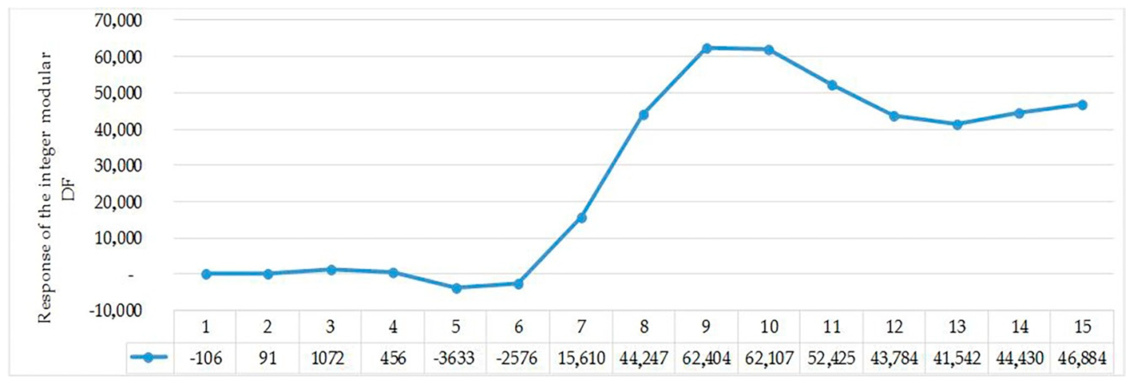
To estimate the accuracy of calculating the output sample of the modular DF, it was necessary to multiply the obtained results by the correction factor [
12]. The results of this estimation are shown in
Figure 6.
The response of the DF, shown in
Figure 5 (the response of the positional DF), coincides with the response shown in
Figure 6 (the response of the integer modular DF using the developed scaling method). The provided example of the estimation of the accuracy of calculating the output sample of the modular DF, which processes 16-bit input data and has 16-bit coefficients, has shown the correctness of the operation of the digital filtering algorithm implemented in the algebra of the finite residue field.
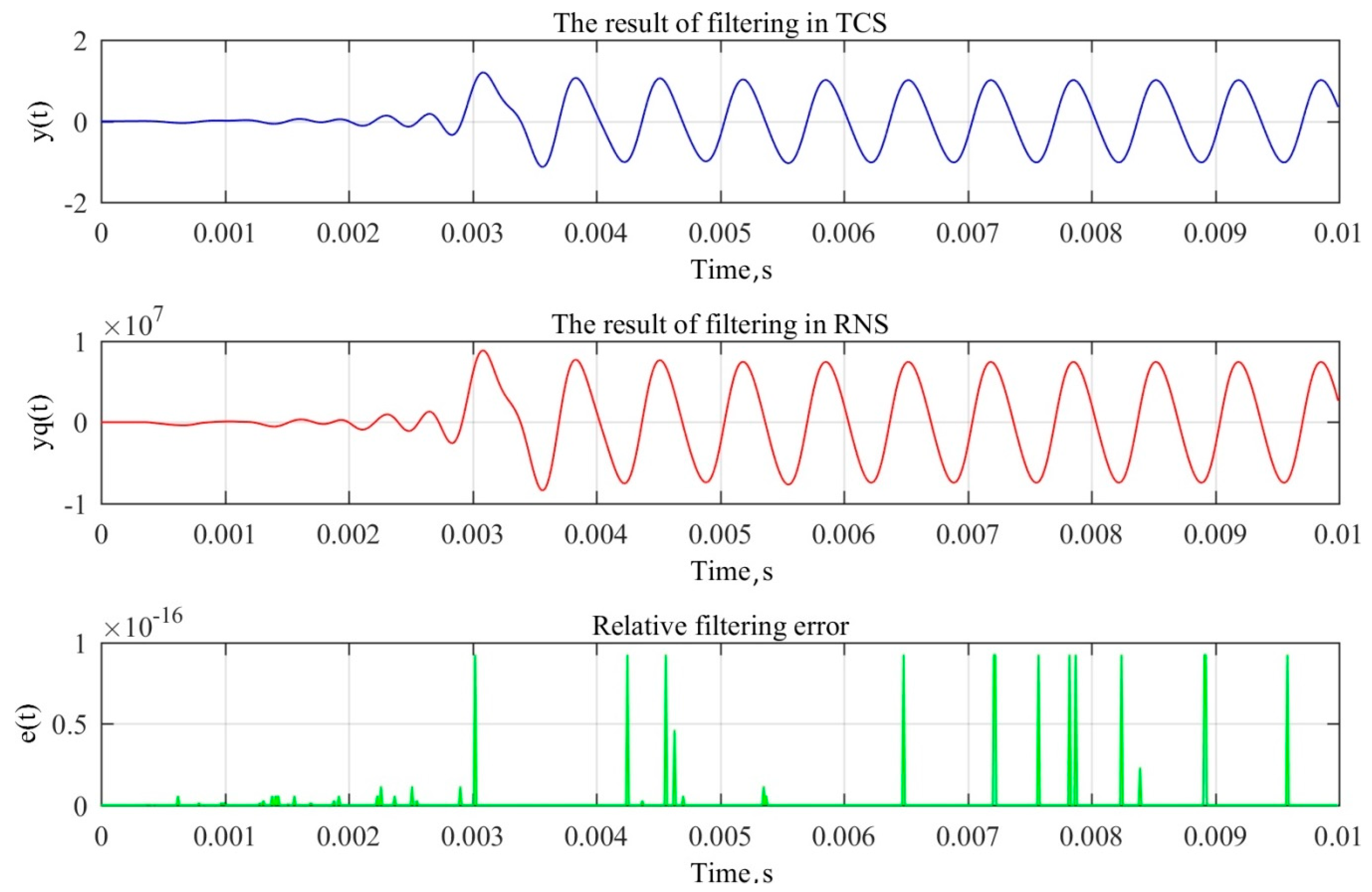
Another example considered in this study was the lowpass FIR filter of order 607. Its parameters are given in
Table 8.
We used multi-harmonic signal with frequencies f1 = 1500 Hz, f2 = 3000 Hz and f3 = 4500 Hz. The RNS filter has the 16 bit depth and traditional filter was implemented with double precision.
Figure 7 shows that the output signals of positional and RNS filters were almost identical. The error, calculated as a difference between outputs, was about 10
−14. This error tends to reduce while the bit depth of RNS filters increases, therefore, it was possible to construct more efficient signal processing devices on low-precision electronics or to increase the performance of existing solutions by changing to the residue field algebra.

 ,
, 


