Article

Virtual Inertia-Based Control Strategy of Two-Stage Photovoltaic Inverters for Frequency Support in Islanded Micro-Grid

1
Key Laboratory of Control of Power Transmission and Transformation, Ministry of Education, Department of Electrical Engineering, Shanghai Jiao Tong University, Shanghai 200240, China
2
Sichuan Electrical Power Research Institute, Chengdu 610000, China
*
Author to whom correspondence should be addressed.
Electronics 2018, 7(11), 340; https://doi.org/10.3390/electronics7110340
Submission received: 8 October 2018 / Revised: 15 November 2018 / Accepted: 16 November 2018 / Published: 21 November 2018
(This article belongs to the Special Issue Grid Connected Photovoltaic Systems)

Abstract

:
For an islanded micro-grid with a high penetration of photovoltaic (PV) power generators, the low inertia reserve and the maximum peak power tracking control may increase the difficulty of maintaining the system’s supply–demand balance, and cause frequency instability, especially when the available generation is excessive. This will require changes in the way the PV inverter is controlled. In this paper, a virtual inertia frequency control (VIFC) strategy is proposed to let the two-stage PV inverters emulate inertia and support the system frequency with a timely response (e.g., inertia response), and the required power for inertia emulation is obtained from both the DC-link capacitor and the PV reserved energy. As the rate of the system frequency change can be reduced with the inertia increase, the proposed method can mitigate the frequency contingency event before the superior-level coordination control is enabled for the frequency restoration. The simulation results demonstrate the effectiveness of the proposed method.

1. Introduction

Driven by the need to improve power supply reliability, reduce CO2 emissions so as to mitigate climate change, and provide reliable electricity to areas lacking electrical infrastructure, the world’s electricity system is developed towards “decentralized, decarbonize, and democratize” [1]. Micro-grid has emerged as a flexible architecture for deploying distributed energy resources (DERs) that can meet the wide-ranging needs of different communities. A number of micro-grid definitions [2] and functional classification schemes [3] can be found in the literature. A broadly cited definition, developed by the United States Department of Energy, is “a group of inter-connected loads and distributed energy resources within clearly defined electrical boundaries that acts as a single controllable entity with respect to the grid. A micro-grid can connect and disconnect from the grid to enable it to operate in both grid-connected or island mode [4].” Based on this definition, DER installations could be considered as micro-grids if comprised of the following three distinct characteristics: they must have electrical boundaries that are clearly defined; there must exist a master controller to control and operate the DERs and loads as a single controllable entity; and the installed generation capacity must exceed the peak critical load, as it could be disconnected from the utility grid (i.e., the islanded mode) and seamlessly supply local critical loads. These characteristics further present micro-grids as small-scale power systems with the ability of self-supply and islanding, which could generate, distribute, and regulate the flow of electricity to local customers or remote areas [1], as shown in Figure 1.
As the micro-grid has proven to be an effective way to make widespread DER deployment more manageable, for example through solar photovoltaics (PVs), wind power, and fuel cell storages, the capacity of the installed DERs in micro-grids has been growing rapidly in recent years, and a high penetration level is expected in the next two to three decades. Among the numerous DER generators, the total capacity of the installed PV generator has grown exponentially, which becomes a major source employed in micro-grids to supply the electrical and thermal loads, especially in remote areas [5,6]. In the foreseeable future, cost-reductions in the production of PV modules will lead to a high penetration of PV power in micro-grids.
However, the high penetration of PVs will bring significant challenges to the micro-grid; as most of the PV generators are connected to the micro-grid through inverters, because of the electricity generated by these sources, is not compatible with the grid [7]. In comparison to the conventional synchronous generators (SGs), the inverter-based PVs have no rotating inertia (rotor) or damping (mechanical friction and damper windings); thus, enough inertia and damping cannot be provided to the micro-grids, which makes the micro-grid systems have a low-inertia, and weakens the frequency regulation capability [8]. Additionally, the high penetration of the PV generators will further degrade the micro-grid stability, especially during the islanded mode [9,10]. Once the micro-grid has less/no support from the conventional rotating machines, the point of the common coupling (PCC) voltage will be established by the controlled voltage-source converters, which have grid-forming capabilities, however, with no rotating masses [8,11]. Additionally, for an islanded micro-grid with multiple PV generators, the micro-grid may become vulnerable to external fluctuations, because of the lack of support from the main grid. What is more, the popular maximum peak power tracking (MPPT) algorithm can even worsen the imbalance between the supply and demand, when the maximum PV power is more than what is required. As inertia stands for the sensitivity of the frequency to a supply–demand mismatch, the variation of generation or load may cause a rapid change and a large deviation of the frequency because of the low inertia, possibly leading to a system instability.
It will be beneficial to the frequency stability if the inverter-based PV generators can provide a grid support function, which is traditionally performed by conventional rotating machines. One solution, called the virtual synchronous generator (VSG), has been proposed to mimic the steady state and transient characteristics of the SGs by applying a swing equation in the inverter control strategies [12,13,14,15,16]. In the energy point of view, SGs store a large amount of kinetic energy because of the intrinsic inertia provided by the large rotational masses, and the absorption or release of the kinetic energy for the power imbalance compensation causes a change in the rotor speed, which directly affects the system frequency. Clearly, for each PV generator, the implementation of this control strategy needs extra energy to synthesize the virtual rotational inertia.
In general, the energy requirements are addressed by incorporating the energy storage [17,18]. However, a high cost and limited lifetime makes this solution not very cost effective. An alternative way is to reserve some of the margins of active power by modifying the control algorithm of the PV system to operate below the maximum power point; thus, the available power can be released when necessary. As this will incur an opportunity cost, it has historically been of little interest for the grid-tied PV system operators. However, in scenarios with a very high penetration of renewable energy, PV systems with a dispatch ability and operating reserves are increasingly of interest [19,20,21,22,23]. A Newton quadratic interpolation-based control method is proposed in the literature [19], in order to enable the PV system to flexibly adjust the active power output in some range, according to the dispatch commands. A cost-effective solution is proposed in the literature [20] for PV generators, which routinely employs a MPPT control to estimate the available PV power, and a constant power generation control to achieve the power reserve. In the literature [21], a more practical control scheme for PV systems is proposed so as to maintain the operating reserves at partial shading conditions. Additionally, in some power systems, such as the California independent system operator (ISO), PV plants are already curtailed at times, and hence the PV system can be operated at a reduced level, without incurring an opportunity cost. Therefore, the PV system can provide the desired active power within the limitations of the input solar power availability, without energy storage.
The major challenges in the implementation of these methods include (1) power set-point tracking in fast dynamics and (2) monitoring the variable maximum power to keep track of the maintained reserves [24]. In the literature [25], MPPT-like control algorithms are proposed that involve the perturbation of the operating point in discrete voltage steps, thus exhibiting a mediocre dynamic response. A voltage PI controller is employed in the literature [26] for an enhanced dynamic response; however, the power set point tracking performance is degraded. Furthermore, many methods have been developed for the PV’s available power estimation [27,28,29,30], and most are realized through irradiance/temperature sensors and the PV array polynomial model; although they suffer from the deviation of the MPP under various changes in environmental conditions and a low estimation speed, this method has been widely used in reality because of its simplicity and practicality.
According to the aforementioned studies, it is well known that the solar energy released from the PV array can be arbitrary adjusted using the existing techniques, such as active power reserve and MPP estimation, and it can be significantly faster than the SG’s governor and prime mover. However, compared with the natural inertia response of the SG, it is still relatively slower, even though the total reaction time can be controlled in a sub-second level. As a result, the main negative impact is that the large deviation of the frequency may have already occurred before the available active power is provided during the transients. Whether the method combines a rapid active power control and virtual inertia response mechanism should be well analyzed and established.
As similar inertia responses can be provided through the capacitors’ charging and discharging behavior, the dynamics of the DC-link capacitor are used to mimic the dynamic of the SG’s rotor in the literature [31], however, the adjustable ability is limited because of the capacitor size and the voltage regulation range. The authors of [32,33] reduce the maximum frequency excursion during a short-time fault by adjusting the PV array’s output, however, the DC-link dynamics have not been addressed. A method modulating the output power of a grid-interactive PV inverter rapidly to a new power level to mitigate frequency contingency events has been proposed in the literature [34], however, a phase-locked loop (PLL) is needed to detect the grid frequency for the implementation of the control law, while the PLL dynamic can be deteriorated when the grid is relatively weak, which may seriously degrade the controller efficiency [35]. The authors of [36] present a control strategy to improve the frequency damping by adjusting the DC-link voltage and PV array generation simultaneously, however, the inertia responses have not been fully investigated for the inverter control, thus the rate of change in frequency is almost unchanged, and the PLL is still needed in this method.
Furthermore, the operation point of the PV generator determines the PV array output power and the degree of up- and down-active power regulating that the PV system can provide; because of the intermittency and volatility of the solar power, a coordination control should be applied to manage the operation point of each PV generator well so as to meet the load supply demand. One feasible solution proposed in the literature [20,37] is to make all of the PVs have the same utilization level, which means the same reserve ratio with respect to their maximum available power, so that the frequency can be supported by uniformly adjusting the aggregated power generation of multiple PV generators within their power limit. However, as the inertia performance does not exist, the maximum power point of each PV generator and the load conditions must be measured in advance in order to update the coordination commands in a very short time interval, which is an uneasy task in practice.
In this paper, a virtual inertia frequency control (VIFC) strategy is proposed for the two-stage PV generators in an islanded micro-grid. By considering the primary power control, DC-link dynamics, and the swing equation-based inverter control, sufficient energy from both the capacitor and the PV array can be provided rapidly for inertia synthesis, and the inertia performance can also be achieved, which helps to support the frequency during the transient. The main contributions of this paper are summarized as follows:
  • The frequency issue of an islanded micro-grid with a PV generator and droop-based grid-forming inverters is focused and analyzed, and a feasible solution based on the virtual inertia frequency control is proposed for the PV generator so as to support the system frequency during the transient, which degrades the maximum deviation of the frequency and its rate of change.
  • The self-synchronization can be achieved by emulating the SG’s swing equation in the control of the inverter, which avoids the impact of the PLL dynamics on the controller.
  • Various simulations are performed with switch-level micro-grid models. The simulation results demonstrate the effectiveness of the proposed control solution.
The rest of this paper is organized as follows: Section 2 introduces the principle and implementation of the VSG control method applied in the inverter with an ideal DC source. Section 3 gives the details of the controller design, and the performance of the proposed controller when operating in parallel with the droop-based inverter is analyzed in Section 4. Section 5 presents the simulation results and Section 6 concludes this paper.

2. Virtual Synchronous Generation Control for Inverters with Ideal DC Sources

2.1. Principle and Implementation

The VSG control scheme investigated in this section consists of a three-phase inverter connected to a grid or a load through an LC filter and the inductive transmission line, as shown in Figure 2. The DC source is assumed to be an ideal one, with enough capacity and a constant DC voltage, which is beneficial to achieve the inertia effect represented by the rotating mass of SG through the VSG control strategy.
The dominant behavior of SGs in terms of the inertia response and damping can be modelled by adding the traditional swing equation into the power control loop, by introducing the mechanical time constant, T a , it can be expressed in p.u., as follows:
T a d ω r d t = p s e t p i n v D ( ω r ω o )
where ω o , p s e t and p i n v are the nominal angular frequency, scheduled power, and inverter output power, respectively. Thus, the virtual rotor angular frequency, ω r can be obtained from Equation (1), and the phase angle reference, θ r is given by the integral of ω r , then θ r will be used for the transformation between the rotating reference frame defined by the VSG inertia and the three-phase signals. The voltage amplitude reference, E r e f can be given by the conventional droop-based reactive power controller. In this paper, the reactive power control of the VSG is considered as decoupled from the inertia emulation, and the amplitude of the inverter output voltage can be fixed as E o .

2.2. Synchronous Operation Mechanism

In the micro-grid islanded mode, droop-based inverters can act as the grid forming units to build the system frequency and voltage, thus ω o (=1 in p.u. with the base value ω B ) is given as a nominal frequency of the system. As the VSG-based inverters are designed for frequency modulation, ω o is also used in VSG controller instead of ω g or ω p c c to regulate the system frequency to the normal value under disturbances, and the power balance of the VSG swing equation will ensure the synchronization to the point of common coupling (PCC) voltage, without the need for a synchronization unit (e.g., PLL and its variants). The relationship between each voltage vector is depicted in Figure 3.
Although, the droop control methods can well emulate the steady-state characteristics of the SG governors with a speed droop, D for proper load sharing among parallel units. For traditional SGs, in the absence of speed governors, the system’s response to a load change is determined by the inertia coefficient and the damping factor; the damping factor here mainly corresponding to the D in the VSG control for reducing the oscillation of the virtual rotor, and keeping it stable at a synchronous speed. Meanwhile, the inertia in SG is derived from the rotor physical characteristics, in the form of the kinetic energy released by the rotor because of its speed change. For the VSG control, the energy for the inertia emulation is obtained from the DC-link, by adding the inertia item in the inverter’s controller, which determines the rate of frequency change.
Numerous research has proved that the VSG control can be well implemented in the inverters with the ideal DC sources, which are assumed to have enough capacity for supplying the required energy. However, for the PV systems with no or insufficient storage as an energy buffer, the input DC source with a variable DC voltage cannot be considered as an ideal one, thus the front-end DC/DC converters are always implemented so as to stabilize the DC-link voltage or to realize the MPPT control. Additional control strategies should be designed to implement the VSG control for the two-stage PV generator.

3. Design and Operation of the VIFC Strategy in Islanded Micro-Grid

Reconsidering the system topology described in Section 2, the PV array connected with the boost converter is added as the front stage of the PV system in this paper, as shown in Figure 4. According to the structure of the control object, the proposed control strategy can be divided into the following three parts, from the front stage to the end stage of the PV system: the primary power adjustment by controlling the boost converter, the inertia emulation control of the DC-link capacitor, and the synchronous control of the inverter. The details of the proposed control strategy development are described as follows.

3.1. Primary Power Adjustment

Here, we developed the PV-side control mechanism in order to rapidly provide sufficient primary power to the inverter-side when the frequency event occurs. For a large load connection in an islanded micro-grid, if there is no additional energy supplement, the voltage of the capacitor will continue to drop and may cause system instability. Although the operation point of the generators can be adjusted by the superior coordination control, it will take at least seconds, and the transient performance cannot be improved.
Thus, the feedbacks of the virtual frequency differential item ( ω ˙ r ) is introduced to change the operation point of the PV generator, as follows:
p s e t = p s e t _ 0 T e d ω r d t D e ( ω r ω o )
where p s e t _ 0 presents the initial set-point, p s e t is the applied reference value of the PV output power. T e and D e are defined as the power control coefficients, which are the positive constants.
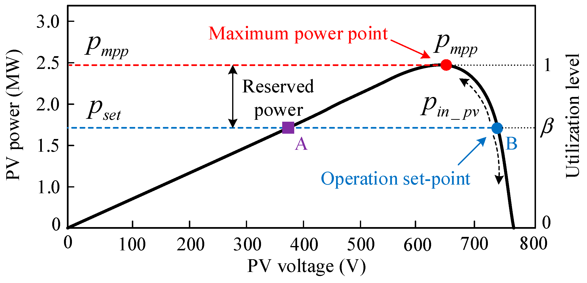
The initial power set-point p s e t _ 0 can be calculated based on the aggregated power of the PV system and the total load demand in a centralized or distributed manner, for example, through an energy management controller or consensus algorithms [38,39]. Based on the overall available generation, p G _ t o t a l and the load demand p L _ t o t a l of the islanded micro-grid, the utilization level, β , can be calculated as β = p L _ t o t a l / p G _ t o t a l . For each PV generator, the initial power set-point can be generated as p s e t _ 0 = β p m p p , where p m p p is the estimated maximum power (MPP) of the individual PV generator. In order to estimate the MPP while operating at a reduced power level, the concept of curve fitting, presented in the literature [24], is adopted here, where the fundamental equation of the single-diode PV model is fitted to a set of past measurements, such as the voltage and the power of the PV system around the current operating point. The model parameters are thus estimated and the MPP is determined. Thereafter, p s e t can be acquired according to Equation (2). In order to facilitate understanding, an indicative power–voltage (P–V) curve of a PV array is shown in Figure 5 (black continuous line), along with the desired power reference level, p s e t (blue dotted line). It can be seen that two possible operating points lie at either side of the MPP, operating point A (purple square marker) and operating point B (blue circle marker). However, when the PV generator runs at point A, the relationship between the power and voltage in the left-hand side is the positive feedback, which causes instable operation. On the contrary, the latter can provide an increased robustness under a fast power point variation, which is chosen as the desired operating point. Depending on the modified MPPT algorithm [40], the PV output power can be regulated under a certain power reserve.
In the steady state, the supply–demand balance is maintained, so the PV output power is equal to the initial power reference value, shown as p i n _ p v = p s e t _ 0 . When the frequency event occurs (e.g., a load step change or distributed generators (DGs) outage), the task of the differential item, T a ω ˙ r here is to let p s e t change rapidly according to the frequency dynamic, which can be represented by the virtual rotor angular frequency, ω r , so that PV system can be controlled to release sufficient energy for supporting the frequency, until a new supply–demand balance is achieved. However, for the case of the micro-grid generation shortage, all of the PV generators should be operated in the MPPT mode, and the utilization level will be maintained at 1.

3.2. Inertia Emulation of the Capacitor

As mentioned above, the energy transfer media are different between the inverters and the rotational synchronous generators from the energy transfer standpoint (i.e., conventional generators convert the mechanical power of prime movers to the electromagnetic power through its rotor’s rotational kinetic energy). Additionally, the energy medium of inverter-based generation systems is the static capacitor, which achieves the power balancing between prime movers (wind, solar, etc.) and grid tied inverters by charging and discharging. In this sense, the inverters and rotational synchronous generators, which are distinguished mainly through their mechanical behaviors (i.e., static or rotational), play an equal role in their respective system, and the behaviors of their energy transfer media can be described by the same fist-order kinetic equation [41]. Thus, the dynamic behavior of the DC-link capacitor can be regarded as the intrinsic inertia of the inverters, which is similar to the intrinsic inertia that comes from the rotational rotor of the synchronous generators. However, the primary power adjustment is used to increase the inertia of the grid-tied inverter based on the proposed control strategy, which belongs to virtual inertia instead of intrinsic inertia. For the investigated PV system, although the total reaction time of the primary energy control (in milliseconds level) can be much faster than the traditional SG (in minutes level), it is still slower than the natural inertia response. When the power unbalance occurs, however, with no or sufficient capacitor as an energy buffer, the frequency may drop immediately so as to exceed the limit before the primary energy adjustment action. On the other hand, it is not enough to rely solely on the energy stored in the capacitor for the inertia response, the extra energy from the PV side can be used as a supplement to emulate the inertia during the process of frequency regulation.
According to the above analysis, for assigning the specific inertia response to the PV system by the capacitor, the variable DC reference should be defined for the proper control of the DC voltage. We assume that the similar inertia response of the SG with a specific mechanical time constant, T c can be emulated by the capacitor yields, as follows:
p i n _ p v p o u t _ p v = T c d ω r d t = V d c C d c S B d V d c d t
where p o u t _ p v can be regarded as the active power delivered from the DC-side to the AC-side. T c represents the SG mechanical time constant corresponding to the capacitor inertia response, V d c and C d c refers to the DC-link voltage and capacitor, respectively. S B is the base value of the power capability.
By integrating both sides of Equation (3) and the linearization for reducing the computational complexity, we have the following
V d c _ r e f = V d c _ 0 + T c S B C d c V d c _ 0 ( ω r ω o )
where V d c _ r e f is the dc-link voltage reference, V d c _ 0 is the nominal DC-link voltage, and ω o is the nominal frequency, all of which are the specified values of the integration constant.
Let k r = T c S B / C d c V d c _ 0 , then the DC-link voltage reference can be acquired as follows:
V d c _ r e f = V d c _ 0 + k r ( ω r ω o )
Thereafter, the DC-link voltage tracking control can be achieved in the current control loop using the proportional-integral (PI) controller, as follows:
i d _ r e f = ( k p + k i s ) [ V d c _ 0 + k r ( ω r ω o ) V d c ]
As a typical inverter modeling process, the d-axis is aligned with the grid voltage vector, according to the vector diagram depicted in Figure 3, and we then have the following:
i d = E X sin δ r
The inner current control loop is designed much faster than the outer virtual inertia control loop, thus, ignoring the transient process of the current tracking yields, we have the following:
i d _ r e f = i d = ( k p + k i s ) [ V d c _ 0 + k r ( ω r ω o ) V d c ]
where k p and k i are the proportional and integral gains of the DC voltage control loop, respectively. Combining Equations (7) and (8), we have the following:
E x L sin δ r = ( k p + k i s ) [ V d c _ 0 + k r ( ω r ω o ) V d c ]
Let K i = E / x L , by linearizing the Equation (9) yields, as follows:
K i s Δ δ = ( s k p + k i ) ( k r Δ ω r Δ V d c )
As s Δ δ can be replaced by Δ ω r , then the relationship between the DC voltage deviation and frequency deviation can be obtained as follows:
Δ ω r = k p s + k i k p k r s + ( K i + k r k i ) Δ V d c
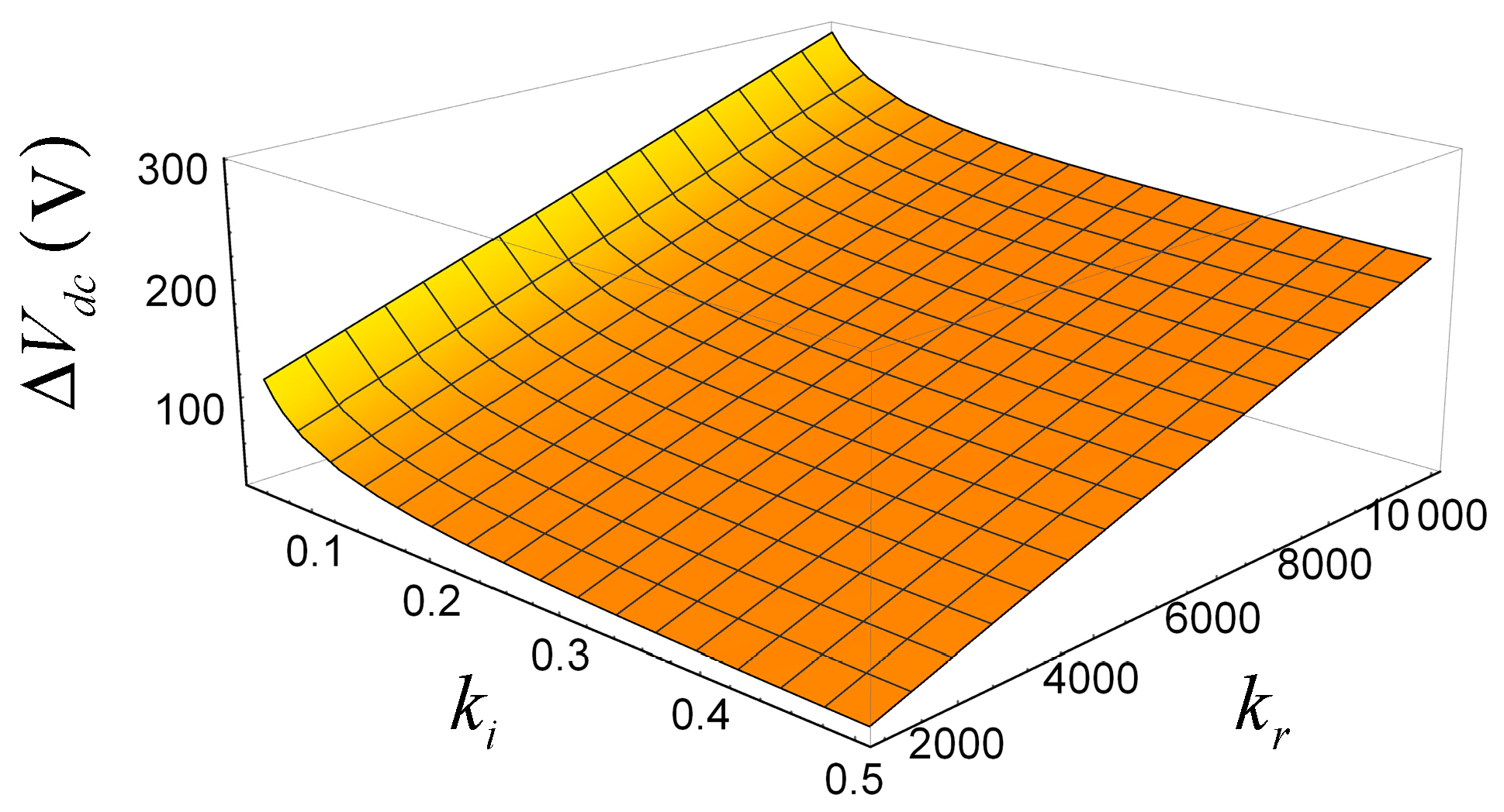
Figure 6 shows the variation of Δ V d c for different k i and k r under certain Δ ω r (=0.02 p.u.) and K i (=240). It can be seen that a smaller k i or larger k r will increase the maximum deviation of the DC-link voltage under a certain frequency deviation, as k r is proportional to the inertia constant T c and inversely proportional to C d c , which indicates that the maximum inertia time constant that the capacitor can provide is dependent on the degree of permissible DC voltage variations and the value of the capacitor.

3.3. Virtual Inertia-Based Synchronized Control of Inverter

In order to emulate the synchronization mechanism of SG, the virtual rotor angular frequency, ω r , can be obtained as follows:
ω r = 1 1 + τ f s [ ω o n p ( p i n v p o u t _ p v ) ]
where τ f represents the time constant of the frequency regulation loop, n p is the equivalent active power droop gain, and p i n v is the output active power of the inverter.
For this control part of the proposed control method, the virtual frequency, ω r , is produced from Equation (12) instead of ω g produced by PLL, and the local measurements can be used for the Park transformation (synchronization control), primary power adjustment, and DC-link voltage reference generation. Furthermore, by putting the power items on the left side of Equation (12), and replacing τ f and n p with T a / D a and 1 / ω o D a , respectively, we have the following yield:
p o u t _ p v p i n v = T a d ω r d t + D a ( ω r ω o )
Furthermore, by combining Equation (13) with Equations (2) and (3), we have the following:
p s e t _ 0 p i n v = T H d ω r d t + D H ( ω r ω o )
where
{ T H = T e + T c + T a D H = D a + D e
From Equation (15), the total inertia time constant, T H , and the damping factor D H , are developed in order to emulate the inertia and to provide the damping using the reserved energy from the PV generation and the dynamics of the DC-link voltage. As the DC and AC power are decoupled in the two-stage configuration of the PV system, the values of T e and T c can separately affect the inertia emulation of the PV generation control and the DC-link voltage control. Furthermore, the selection of T c depends on the value of k r , in Equation (5), which is related to the DC-link voltage regulation. The implementation of the inverter control can be achieved using the inner current control loop [42] so as to generate the modulation wave, as shown in Figure 7. The performance of the controller and the effect of the parameters will be analyzed in the next section.

4. Parallel Operation with Droop Based Grid-Forming Inverters

In this section, an investigation into how the VIFC strategy affects the dynamic response of the PCC voltage frequency during the load changes is shown.
We consider a micro-grid operated in an islanded mode, with droop-based inverters acting as the grid-forming units to keep the PCC voltage stable, and the whole active power consumed by the load is shared by the parallel connected PV inverters and the droop-based inverters, from the law of conservation of energy, as follows:
Δ p i n v + Δ p d r o o p = Δ p l o a d
where Δ p d r o o p represents the output power of the droop-based inverters, and p l o a d is the active power consumed by load. The PCC frequency is managed by the paralleled inverters and is represented as ω p c c .
Let Δ p i n v / Δ ω p c c = A , Δ p d r o o p / Δ ω p c c = B , we have
Δ ω p c c Δ p l o a d = 1 A + B
For the PV systems, the cable between the units and the load is considered inductive, and by calculating the power flow, Equation (18) can be deduced as follows:
Δ p i n v = E U p c c cos δ r Δ δ r / x L
Knowing that Δ δ r = ( Δ ω r Δ ω p c c ) / s , let K m = E U p c c cos δ r / x L , so that Equation (18) becomes the following:
s Δ p i n v K m ( Δ ω r Δ ω p c c )
The small signal model of Equation (14) can be written as follows:
Δ p i n v = T H s Δ ω r + D H Δ ω r
Replacing Δ ω r with Δ ω p c c in Equation (20), according to Equation (19), A can be obtained as follows:
A = Δ p i n v Δ ω p c c = T H s + D H T H K m s 2 + D H K m s + 1
Similarly, according to droop control strategy, B can be obtained as follows:
B = Δ p d r o o p Δ ω p c c = k d 1 + ( k d / K m ) s
where k d is the droop coefficient.
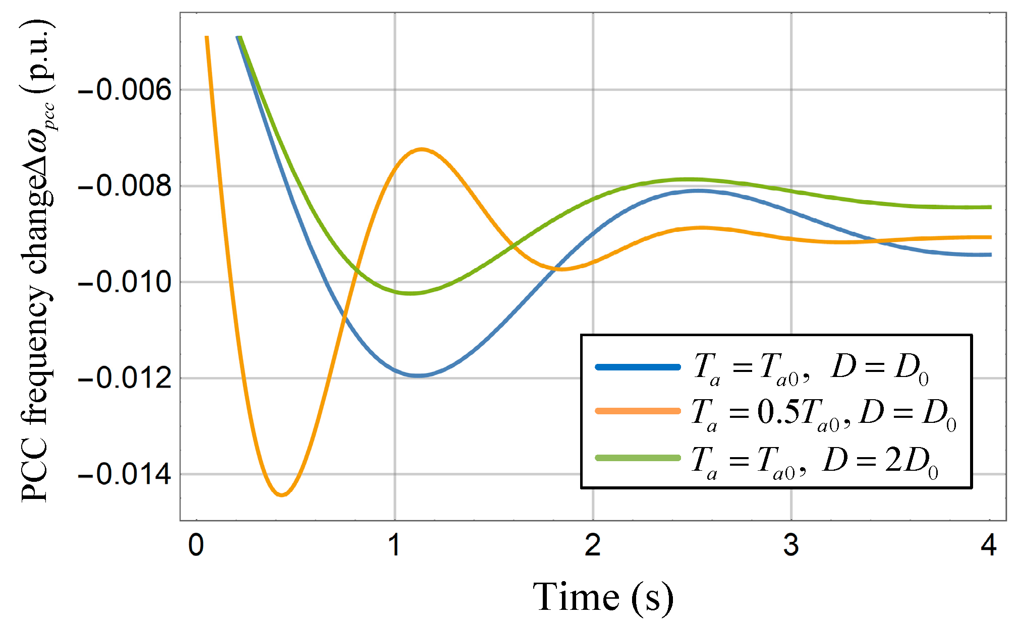
Based on Equations (17), (21), and (22), it is possible to calculate the step responses of the PCC frequency change during a small loading transition relevant to the VIFC strategy. The corresponding parameters in this case are listed in Table 1, and the results are shown in Figure 8.
As it is demonstrated in Figure 8, the VIFC-based control can contribute more inertia to the system and can regulate the frequency of the micro-grid with the inertia performance. Moreover, a larger value of T H can increase the inertia of the system, and a larger D reduces the maximum frequency deviation. The results demonstrate that the inertia response can be provided flexibly by changing the corresponding parameters.

5. Simulation Studies

During the simulation studies, the proposed control method was tested in an islanded micro-grid with a PV generator and a grid-forming inverter controlled by droop connected in parallel, as shown in Figure 9. The test is divided into two cases, under different operating conditions. In the first case, the contribution to the inertia emulation from the DC-link voltage control and the reserved primary power adjustment were tested, respectively. Furthermore, the PV generator that operated in a MPPT mode under the same operating condition was also tested as a contrast. In the second case, the proposed VIFC method was integrated with the distributed coordination algorithm, and was tested with the variable solar energy in the PV-side. For both cases, the systems’ responses (i.e., PCC frequency, DC-link voltage, and PV output power) to the load step change were fully investigated in order to validate the effectiveness of the proposed control method.
The common process of the simulation studies can be described as follows: The load demand is 20 kW at the beginning. For the PV generator controlled by the proposed control strategy, the initial operation point is set to be 20 kW, so that the generation set-point of the droop-based inverter is set to be 0, as the PV generation is sufficient. A 5 kW load (25% of the total pre-disturbance load) increase occurs at t = 10 s, and the corresponding parameters are listed in Table 1.

5.1. Inertia Emulation Capability Tests

In this case, the maximum power of the PV generator was assumed to be unchanged for a period of time, which was estimated as 30 kW for the proposed control strategy, and the nominal power set-point was 20 kW, with a reserved 10 kW active power for frequency regulation. In contrast, the PV generator operated in the MPPT mode with 20 kW maximum available power, which was assumed to be a constant, so that there was no extra energy for frequency regulation.
The results of the traditional PV control method are shown in Figure 10. Before 10 s, the islanded micro-grid was operated in a supply–demand balance mode, the PV generator presented the available maximum power, which was equal to the load demand, and the frequency was stable at 50 Hz. After 10 s, with the increase of the load, the frequency began to decrease immediately, because of the lack of inertia. As the PV system reached its upper limit of the output power, there was no reserved power that could be provided. Without the support from the PV generator, the frequency stabilized by the grid-forming inverter had a large deviation from the normal value, which was approximately 49.6 Hz. The DC-link voltage and the output power of the PV generators remained unchanged during the disturbance, as shown in Figure 10b,c. As the DC-link voltage kept constant, there was no inertia provided by the capacitors when the power unbalance occurred; if the frequency dropped immediately within 2 ms, as shown in Figure 10a, usually the active power control could not be activated in this short time, and the consequence was consistent with the previous theoretical analysis.
For the proposed control method, the frequency responses are shown in Figure 11 and Figure 12, and the inertia performance can be obtained during the transient. For further investigating, the contribution to the inertia emulation from the DC-link voltage control and the primary power adjustment, different values of k r and T e are implemented to the controller in this tests.
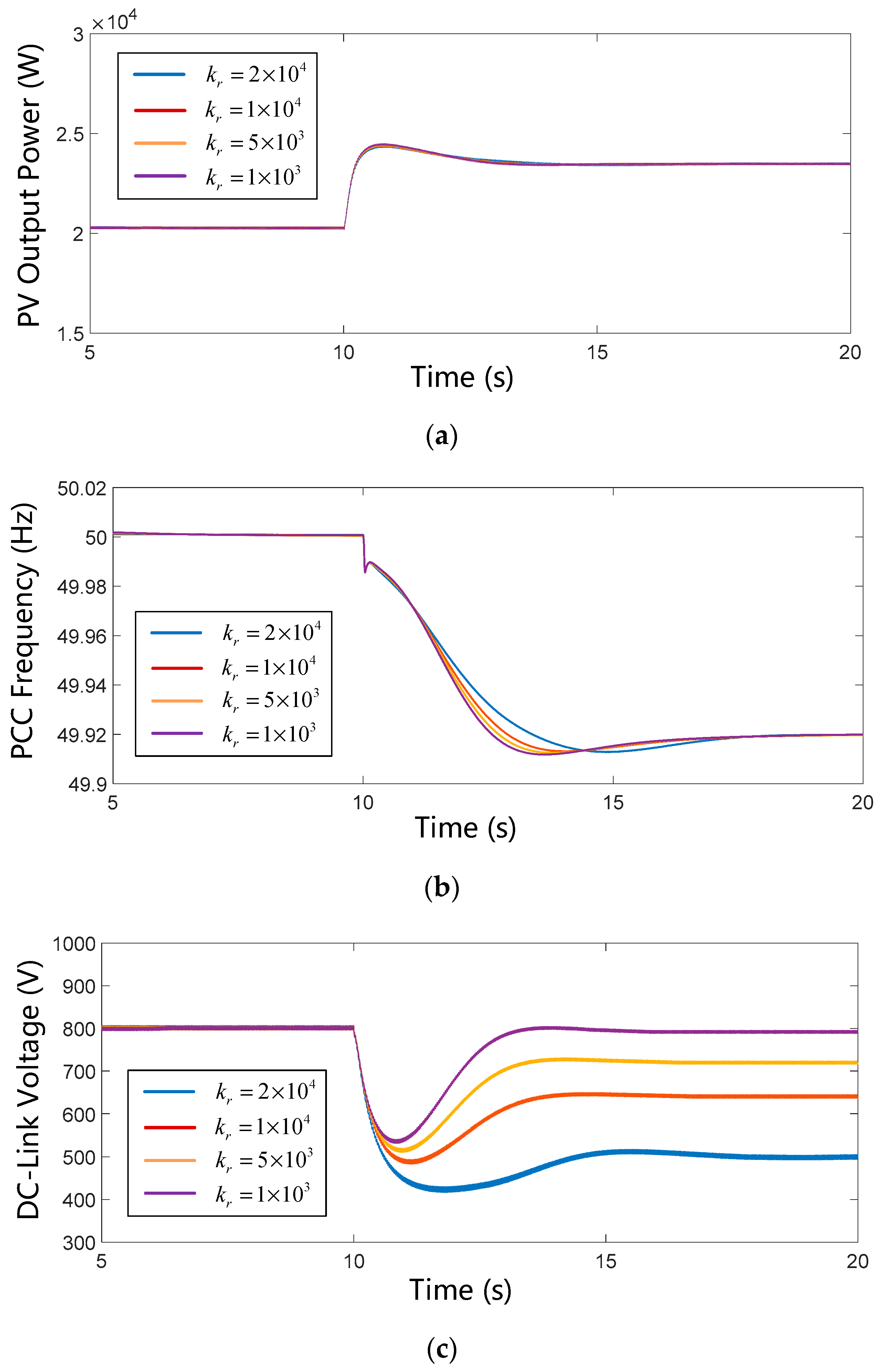
The contribution of the DC-link voltage control is firstly tested. According to Equations (4) and (5), the inertia emulated from the capacitor can be provided by controlling the DC-link voltage, as the size of the capacitor and the nominal DC voltage value are determined, the inertia response from the capacitor is mainly related to the value of k r in Equation (5). The results of the systems’ response to the load step change with different values of k r are shown in Figure 11, and the other parameters are the same as those listed in Table 1.
Figure 11a shows the comparison of the PV generator output power with different values of k r . The overlap curves illustrate that the inertial contributions from the PV-side generation adjustment are almost the same in this case, so the difference of the inertia response mainly depends on the control of the DC-link voltage. Figure 11b shows the PCC frequency responses, demonstrating that the performance of the inertia can be enhanced if the value of k r increases from 1000 to 20,000, however, the effects are not so evident. The corresponding responses of the DC-link voltage are shown in Figure 11c, and it can be seen that the value of k r plays an important role in determining the deviation of the DC-link voltage during and after the transient. Comparing Figure 11b with Figure 11c, we can see that a large DC-link voltage deviation is only capable of emulating a small inertia. It is worthy to note that for an individual two-stage PV system with an 800 V DC-link voltage as the nominal value, the lower bound of the DC-link voltage is normally 600 V in order for the sinusoidal pulse width modulation (SPWM) to be able to produce the appropriate voltage for a 220 V (rms) low-voltage micro-grid, and the upper limit is restricted by the capacitors, which is approximately 1000 V. As a result, in the case of a limited rated capacity of the capacitor and a narrow DC-link voltage range, the contribution of the capacitor to the inertia emulation is very limited, which is consistent with the previous analysis.
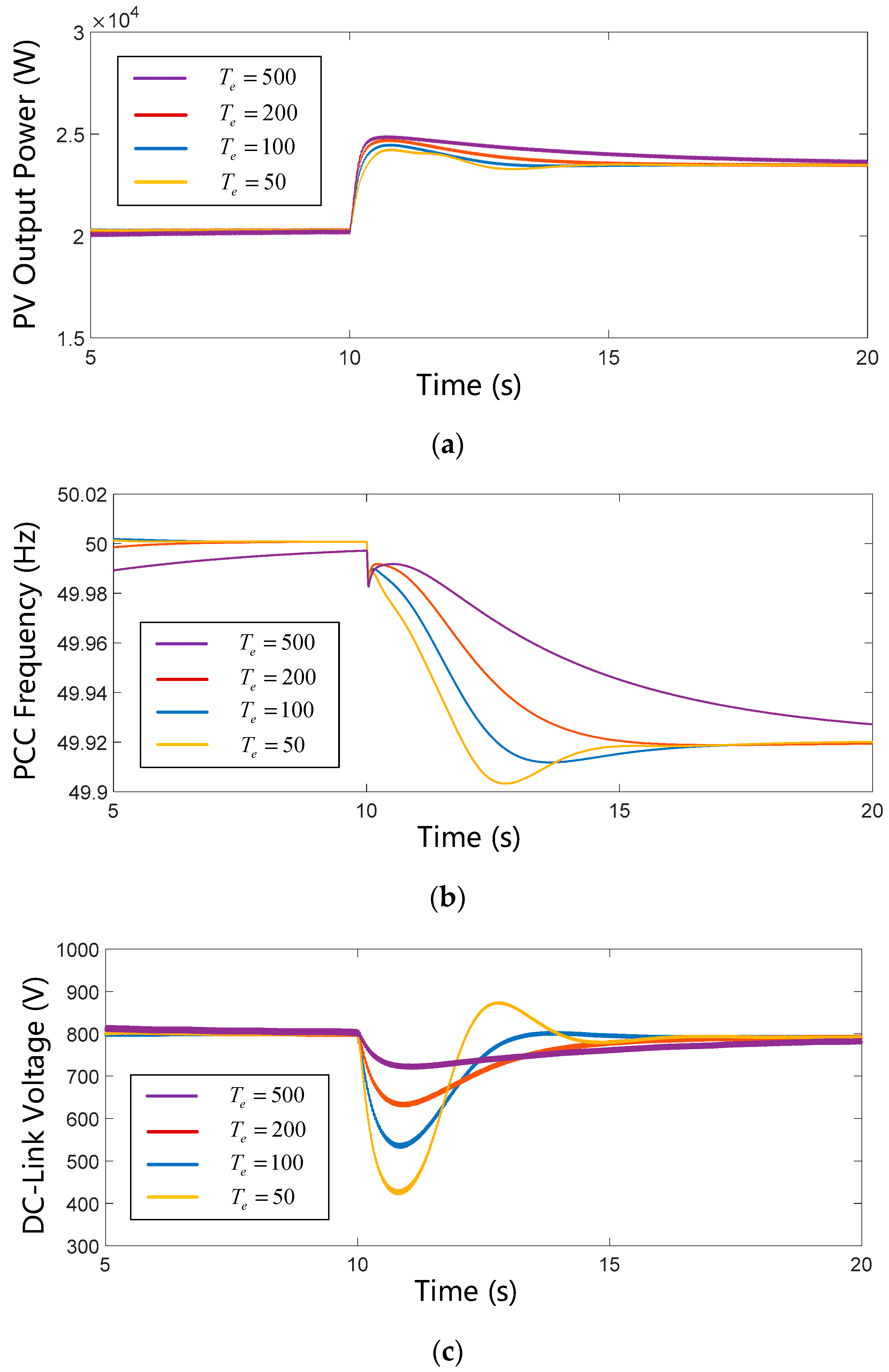
Furthermore, different power control coefficients ( T e ) are applied in the primary power control to investigate the contribution of the PV generation adjustment to the inertia emulation. From Figure 12a,b, we can see that with the increase of T e , the active power released from the PV-side can be improved for more inertia emulation during the transient. Meanwhile, the maximum deviation of the DC-link voltage can be reduced because of the rapid active power injection, as shown in Figure 12c.
It can be concluded that (1) compared with the system responses under the traditional control method, the frequency drop of the PCC under the VIFC strategy is much slower, and the maximum frequency deviation is less than 49.9 Hz, which illustrates that the VIFC-based PV system is able to increase the system inertia and support the frequency for the islanded micro-grid; (2) for an individual PV generator with a relatively low DC-link voltage (800 V), the energy for the inertia emulation mainly comes from the reserved active power. By contrast, the contribution of the capacitor is quite small and comes with the expense of voltage deviation. Thus, a certain amount of primary power reservation and rapid active power control is more necessary for the PV generators to support the system frequency.

5.2. Variable Solar with Load Step Change

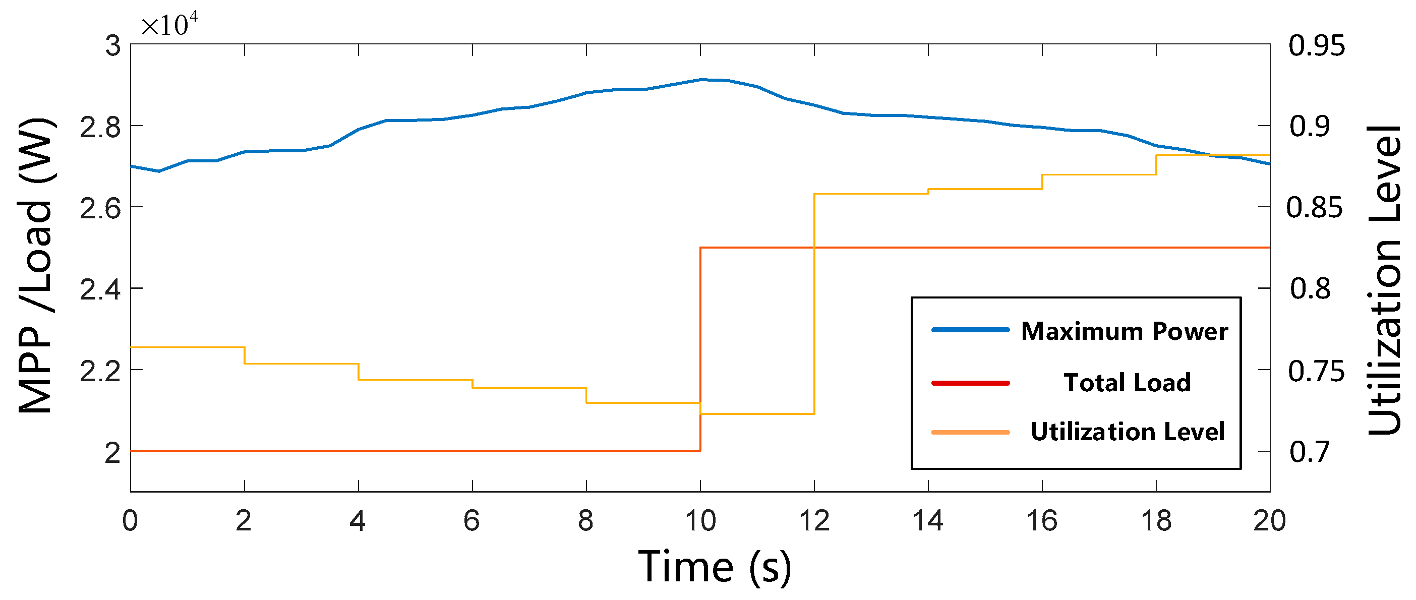
In this case, the variable solar energy is considered, a coordination control algorithm depicted in the literature [43] is applied for calculating the PV nominal power set-point, and the time step for the utilization level update is selected to be 2 s for a good balance between the control performance and the technical feasibility. The utilization level profiles of the PV generator with respect to the maximum available solar power and the total load demand are shown in Figure 13.
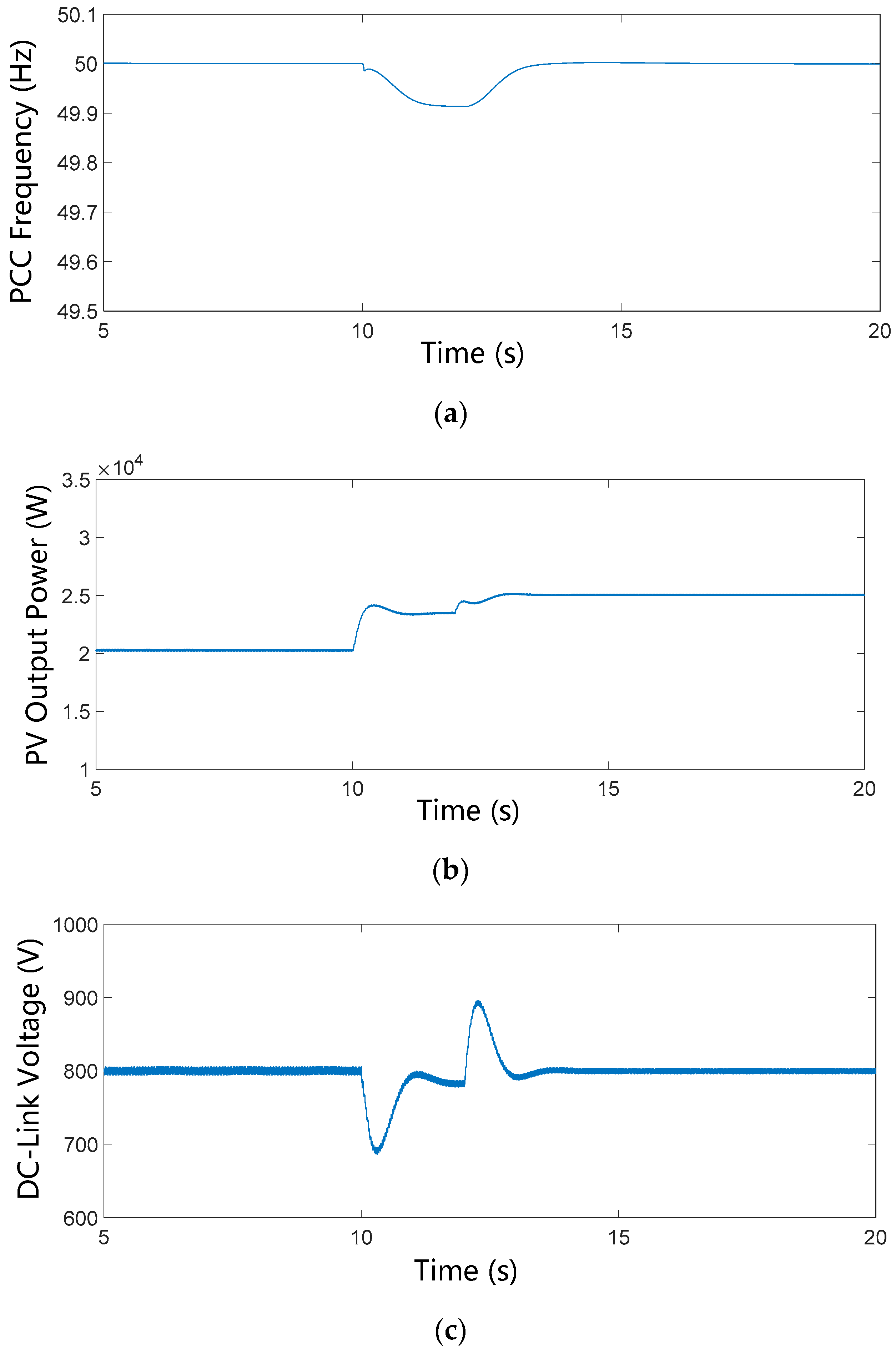
It can be seen that before t = 10   s , the load demand is maintained at 20 kW; as the estimated maximum point of the PV generator increases, the corresponding utilization level is gradually reduced in each update, thus the operation point of the PV system can be controlled as 20 kW. Thereafter, the load step change occurs at t = 10   s , as the coordination control starts to work in the next update interval about 2 s later, the frequency will be supported by the proposed control strategy from 10 s to 12 s. After 12 s, the utilization level is significantly increased for the supply–demand balance, thus the frequency can be restored to the normal value.
Figure 14 shows the responses of the PCC frequency, the PV output power, and the DC-link voltage with respect to the load step change. During the period of 10 to 12 s, similar inertia phenomena can be observed, as is shown in the first case. After the utilization level is updated, the operation point of the PV generator is adjusted and the frequency is gradually restored to the normal value, as shown in Figure 14a, and it can be observed that because of the emulated inertia, the restoration process is also relatively slow. Figure 14b shows the output power of the PV generator, which demonstrates that the operation point of the PV system can be changed automatically according to the virtual frequency variation during the transient. Thus, sufficient energy can be provided from the PV array for the inertia emulation. When the utilization level is updated, the PV generation is controlled so as to be adjusted immediately at t = 12 s, then the capacitor will be charged because of the inertia, and the voltage is increased, as shown in Figure 14c, demonstrating that the similar inertia response is shown in the process of frequency restoration.

6. Conclusions

This paper presents a virtual inertia-based control strategy for two-stage photovoltaic inverter systems in an islanded micro-grid. According to the different control objects of the PV system, the proposed control strategy can be divided into the primary power adjustment, the DC-link voltage control, and the inverter synchronous control. With this method, the inertia response can be provided by the PV generators based on a simplified SG model, and the virtual rotor angular frequency is produced for rapid PV generation adjustment and DC-link voltage reference generation, thus the reserved energy of the PV array and the dynamics of the DC-link voltage can be used to provide sufficient energy for the inertia emulation. Meanwhile, the self-synchronization can be achieved based on the local measurements, so that PLL can be eliminated. When operating in parallel with the droop-based grid-forming inverters, the transient performance of the system frequency can be improved and the demanding requirement for the updating rate of the coordination control can be relaxed, which is suitable for the autonomous micro-grid operation with a high penetration of renewable energies and without the support of SGs. The simulation results validate the effectiveness of the VIFC strategy, and the contribution of the different control parts to the inertia emulation is also investigated by the simulation studies.

Author Contributions

Investigation, X.H.; methodology, X.H.; project administration, H.Z.; supervision, G.L.; validation, X.H.; writing (original draft), X.H.; writing (review and editing), K.W.

Funding

This work was supported by the National Key R&D Plan of China (no. 2016YFB0900504) and the State Grid Sichuan Electric Power Company (no. 52199717001K).

Conflicts of Interest

The authors declare no conflict of interest.

References

  1. Hirsch, A.; Parag, Y.; Guerrero, J. Microgrids: A review of technologies, key drivers, and outstanding issues. Renew. Sustain. Energy Rev. 2018, 90, 402–411. [Google Scholar] [CrossRef]
  2. Olivares, D.E.; Mehrizi-Sani, A.; Etemadi, A.H.; Cañizares, C.A.; Iravani, R.; Kazerani, M.; Hajimiragha, A.H.; Gomis-Bellmunt, O.; Saeedifard, M.; Palma-Behnke, R.; et al. Trends in Microgrid Control. IEEE Trans. Smart Grid 2014, 5, 1905–1919. [Google Scholar] [CrossRef]
  3. Martin-Martínez, F.; Sánchez-Miralles, A.; Rivier, M. A literature review of Microgrids: A functional layer based classification. Renew. Sustain. Energy Rev. 2016, 62, 1133–1153. [Google Scholar] [CrossRef]
  4. Ton, D.; Smith, M. The US Department of Energy’s Microgrid Initiative. Electr. J. 2012, 25, 84–94. [Google Scholar] [CrossRef]
  5. Wu, Q.; Larsen, E.; Heussen, K.; Binder, H.; Douglass, P. Remote Off-Grid Solutions for Greenland and Denmark: Using smart-grid technologies to ensure secure, reliable energy for island power systems. IEEE Electrif. Mag. 2017, 5, 64–73. [Google Scholar] [CrossRef]
  6. Guo, W.; Mu, L. Control principles of micro-source inverters used in microgrid. Prot. Control Mod. Power Syst. 2016, 1, 1–7. [Google Scholar] [CrossRef]
  7. Zhong, Q.-C. Virtual Synchronous Machines: A unified interface for grid integration. IEEE Power Electron. Mag. 2016, 3, 18–27. [Google Scholar] [CrossRef]
  8. Katiraei, F.; Sun, C.; Enayati, B. No Inverter Left Behind: Protection, Controls, and Testing for High Penetrations of PV Inverters on Distribution Systems. IEEE Power Energy Mag. 2015, 13, 43–49. [Google Scholar] [CrossRef]
  9. Liu, J.; Miura, Y.; Ise, T. Comparison of Dynamic Characteristics Between Virtual Synchronous Generator and Droop Control in Inverter-Based Distributed Generators. IEEE Trans. Power Electron. 2016, 31, 3600–3611. [Google Scholar] [CrossRef]
  10. Schiffer, J.; Hans, C.A.; Kral, T.; Ortega, R.; Raisch, J. Modeling, Analysis, and Experimental Validation of Clock Drift Effects in Low-Inertia Power Systems. IEEE Trans. Ind. Electron. 2017, 64, 5942–5951. [Google Scholar] [CrossRef] [Green Version]
  11. Ashabani, M.; Mohamed, Y.A.-R.I.; Mirsalim, M.; Aghashabani, M. Multivariable Droop Control of Synchronous Current Converters in Weak Grids/Microgrids With Decoupled dq-Axes Currents. IEEE Trans. Smart Grid 2015, 6, 1610–1620. [Google Scholar] [CrossRef]
  12. Zhong, Q.-C.; Weiss, G. Synchronverters: Inverters That Mimic Synchronous Generators. IEEE Trans. Ind. Electron. 2011, 58, 1259–1267. [Google Scholar] [CrossRef]
  13. Aouini, R.; Marinescu, B.; Kilani, K.B.; Elleuch, M. Synchronverter-Based Emulation and Control of HVDC Transmission. IEEE Trans. Power Syst. 2016, 31, 278–286. [Google Scholar] [CrossRef]
  14. D’Arco, S.; Suul, J.A.; Fosso, O.B. A Virtual Synchronous Machine implementation for distributed control of power converters in SmartGrids. Electr. Power Syst. Res. 2015, 122, 180–197. [Google Scholar] [CrossRef]
  15. Mo, O.; D’Arco, S.; Suul, J.A. Evaluation of Virtual Synchronous Machines with Dynamic or Quasi-Stationary Machine Models. IEEE Trans. Ind. Electron. 2017, 64, 5952–5962. [Google Scholar] [CrossRef]
  16. Im, W.-S.; Wang, C.; Liu, W.; Liu, L.; Kim, J.-M. Distributed virtual inertia based control of multiple photovoltaic systems in autonomous microgrid. IEEECAA J. Autom. Sin. 2017, 4, 512–519. [Google Scholar] [CrossRef]
  17. Craciun, B.-I.; Kerekes, T.; Sera, D.; Teodorescu, R. Frequency Support Functions in Large PV Power Plants with Active Power Reserves. IEEE J. Emerg. Sel. Top. Power Electron. 2014, 2, 849–858. [Google Scholar] [CrossRef]
  18. Hosseinipour, A.; Hojabri, H. Virtual inertia control of PV systems for dynamic performance and damping enhancement of DC microgrids with constant power loads. IET Renew. Power Gener. 2018, 12, 430–438. [Google Scholar] [CrossRef]
  19. Xin, H.; Gan, D.; Liu, Y.; Chen, L.; Chen, L. A Newton quadratic interpolation based control strategy for photovoltaic system. In Proceedings of the International Conference on Sustainable Power Generation and Supply (SUPERGEN 2012), Hangzhou, China, 8–9 September 2012; p. 62. [Google Scholar]
  20. Sangwongwanich, A.; Yang, Y.; Blaabjerg, F. A Sensorless Power Reserve Control Strategy for Two-Stage Grid-Connected PV Systems. IEEE Trans. Power Electron. 2017, 32, 8559–8569. [Google Scholar] [CrossRef]
  21. Batzelis, E.I.; Papathanassiou, S.A.; Pal, B.C. PV System Control to Provide Active Power Reserves Under Partial Shading Conditions. IEEE Trans. Power Electron. 2018, 33, 9163–9175. [Google Scholar] [CrossRef]
  22. Xin, H.; Liu, Y.; Wang, Z.; Gan, D.; Yang, T. A New Frequency Regulation Strategy for Photovoltaic Systems Without Energy Storage. IEEE Trans. Sustain. Energy 2013, 4, 985–993. [Google Scholar] [CrossRef]
  23. Nanou, S.I.; Papakonstantinou, A.G.; Papathanassiou, S.A. A generic model of two-stage grid-connected PV systems with primary frequency response and inertia emulation. Electr. Power Syst. Res. 2015, 127, 186–196. [Google Scholar] [CrossRef]
  24. Batzelis, E.I.; Kampitsis, G.E.; Papathanassiou, S.A. Power Reserves Control for PV Systems with Real-Time MPP Estimation via Curve Fitting. IEEE Trans. Sustain. Energy 2017, 8, 1269–1280. [Google Scholar] [CrossRef]
  25. Sangwongwanich, A.; Yang, Y.; Blaabjerg, F.; Sera, D. Delta Power Control Strategy for Multi-String Grid-Connected PV Inverters. In Proceedings of the 2016 IEEE Energy Conversion Congress and Exposition (ECCE), Milwaukee, WI, USA, 18–22 September 2016; p. 7. [Google Scholar]
  26. Batzelis, E.; Nanou, S.; Papathanassiou, S. Active Power Control in PV Systems Based on a Quadratic Curve Fitting Algorithm for the MPP Estimation. In Proceedings of the 29th EUPVSEC, Amsterdam, The Netherlands, 22–26 September 2014. [Google Scholar]
  27. Messalti, S.; Harrag, A.; Loukriz, A. A new variable step size neural networks MPPT controller: Review, simulation and hardware implementation. Renew. Sustain. Energy Rev. 2017, 68, 221–233. [Google Scholar] [CrossRef]
  28. Tsang, K.M.; Chan, W.L. Model based rapid maximum power point tracking for photovoltaic systems. Energy Convers. Manag. 2013, 70, 83–89. [Google Scholar] [CrossRef]
  29. Elobaid, L.M.; Abdelsalam, A.K.; Zakzouk, E.E. Artificial neural network-based photovoltaic maximum power point tracking techniques: A survey. IET Renew. Power Gener. 2015, 9, 1043–1063. [Google Scholar] [CrossRef]
  30. Yan, X.; Li, J.; Wang, L.; Zhao, S.; Li, T.; Lv, Z.; Wu, M. Adaptive-MPPT-Based Control of Improved Photovoltaic Virtual Synchronous Generators. Energies 2018, 11, 1834. [Google Scholar] [CrossRef]
  31. Zhu, J.; Booth, C.D.; Adam, G.P.; Roscoe, A.J.; Bright, C.G. Inertia Emulation Control Strategy for VSC-HVDC Transmission Systems. IEEE Trans. Power Syst. 2013, 28, 1277–1287. [Google Scholar] [CrossRef] [Green Version]
  32. Zadeh, M.J.Z.; Fathi, S.H. A New Approach for Photovoltaic Arrays Modeling and Maximum Power Point Estimation in Real Operating Conditions. IEEE Trans. Ind. Electron. 2017, 64, 9334–9343. [Google Scholar] [CrossRef]
  33. Anderson, H.; Eduard, M.; Dragan, M. Real-time Photovoltaic Plant Maximum Power Point Estimation for Use in Grid Frequency Stabilization. In Proceedings of the 2015 IEEE 16th Workshop on Control and Modeling for Power Electronics (COMPEL), Vancouver, BC, Canada, 12–15 July 2015; pp. 1–7. [Google Scholar]
  34. Hoke, A.F.; Shirazi, M.; Chakraborty, S.; Muljadi, E.; Maksimovic, D. Rapid Active Power Control of Photovoltaic Systems for Grid Frequency Support. IEEE J. Emerg. Sel. Top. Power Electron. 2017, 5, 1154–1163. [Google Scholar] [CrossRef]
  35. Huang, L.; Xin, H.; Wang, Z.; Wu, K.; Wang, H.; Hu, J.; Lu, C. A Virtual Synchronous Control for Voltage Source Converters Utilizing Dynamics of DC-Link Capacitor to Realize Self-Synchronization. IEEE J. Emerg. Sel. Top. Power Electron. 2017, 5, 1565–1577. [Google Scholar] [CrossRef]
  36. Pogaku, N.; Prodanovic, M.; Green, T.C. Modeling, Analysis and Testing of Autonomous Operation of an Inverter-Based Microgrid. IEEE Trans. Power Electron. 2007, 22, 613–625. [Google Scholar] [CrossRef]
  37. Bachir, T.O.; Dufour, C.; Bélanger, J.; Mahseredjian, J.; David, J.P. A fully automated reconfigurable calculation engine dedicated to the real-time simulation of high switching frequency power electronic circuits. Math. Comput. Simul. 2013, 91, 167–177. [Google Scholar] [CrossRef]
  38. de Almeida, R.G.; Castronuovo, E.D.; PecasLopes, J.A. Optimum Generation Control in Wind Parks When Carrying Out System Operator Requests. IEEE Trans. Power Syst. 2006, 21, 718–725. [Google Scholar] [CrossRef]
  39. Li, Z.; Zang, C.; Zeng, P.; Yu, H.; Li, S. Fully Distributed Hierarchical Control of Parallel Grid-Supporting Inverters in Islanded AC Microgrids. IEEE Trans. Ind. Inform. 2018, 14, 679–690. [Google Scholar] [CrossRef] [Green Version]
  40. Sangwongwanich, A.; Yang, Y.; Blaabjerg, F.; Wang, H. Benchmarking of Constant Power Generation Strategies for Single-Phase Grid-Connected Photovoltaic Systems. IEEE Trans. Ind. Appl. 2018, 54, 447–457. [Google Scholar] [CrossRef] [Green Version]
  41. Xiong, L.; Zhuo, F.; Wang, F.; Liu, X.; Chen, Y.; Zhu, M.; Yi, H. Static Synchronous Generator Model: A New Perspective to Investigate Dynamic Characteristics and Stability Issues of Grid-Tied PWM Inverter. IEEE Trans. Power Electron. 2016, 31, 6264–6280. [Google Scholar] [CrossRef]
  42. Xiao, L.; Guerrero, J.M.; Yao, Z. Improved control strategy for the three-phase grid-connected inverter. IET Renew. Power Gener. 2015, 9, 587–592. [Google Scholar] [Green Version]
  43. Zhang, W.; Xu, Y.; Liu, W.; Ferrese, F.; Liu, L. Fully Distributed Coordination of Multiple DFIGs in a Microgrid for Load Sharing. IEEE Trans. Smart Grid 2013, 4, 806–815. [Google Scholar] [CrossRef]
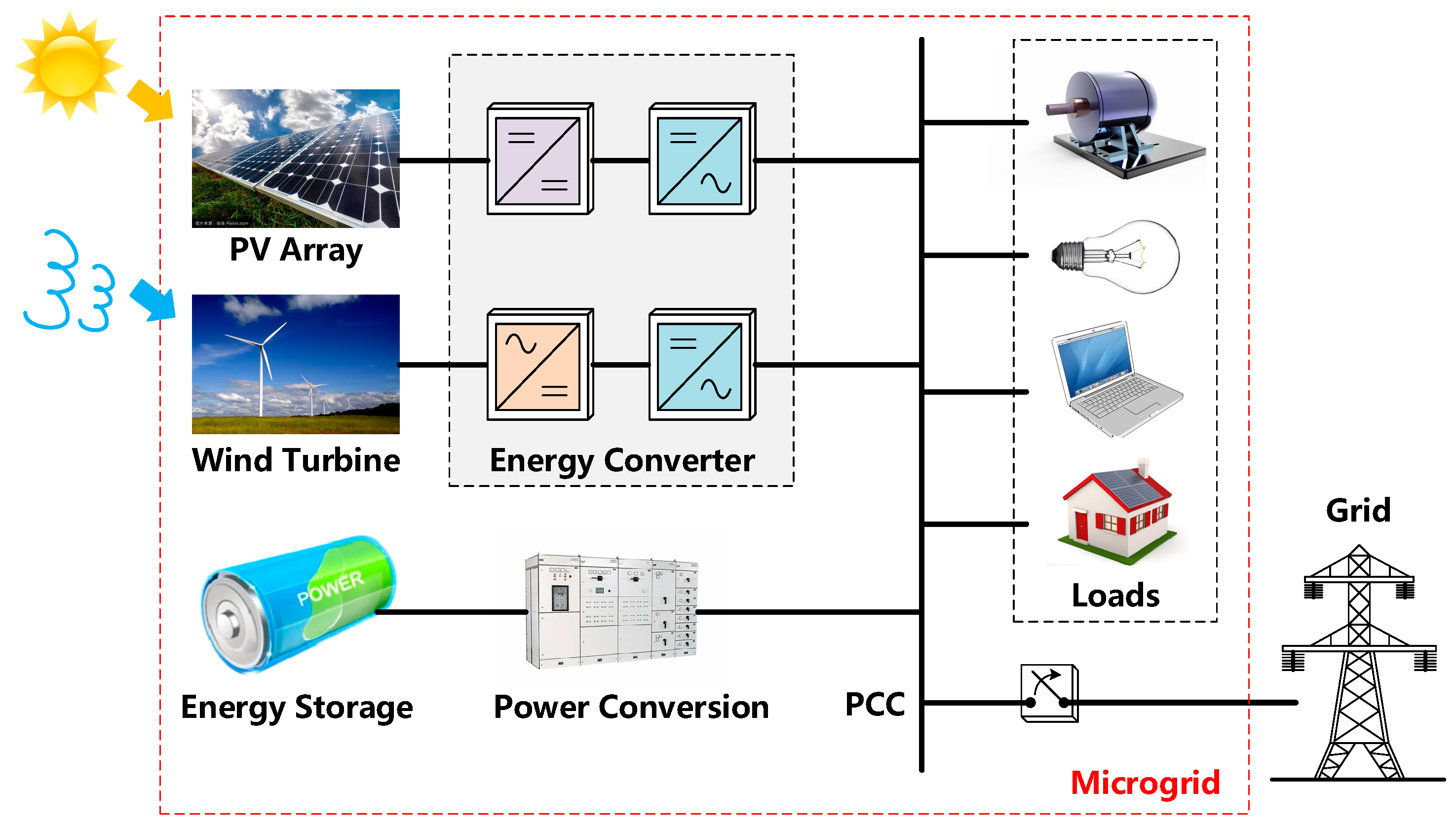
Figure 1. Diagram of the micro-grid.
Electronics 07 00340 g001
Figure 2. Diagram of inverter with an ideal DC source system supplying a grid or a load.
Electronics 07 00340 g002
Figure 3. Vector diagram of synchronous reference axis defining and voltage vector orientation.
Electronics 07 00340 g003
Figure 4. System configuration and control structure of a two-stage photovoltaic (PV) system with a virtual inertia frequency control (VIFC) strategy.
Electronics 07 00340 g004
Figure 5. Power–voltage curve of the PV array with reserved power by operating the PV system at below the maximum point.
Electronics 07 00340 g005
Figure 6. Relationship between DC-link voltage deviation and frequency deviation under different parameters.
Electronics 07 00340 g006
Figure 7. Implementation of the proposed VIFC strategy.
Electronics 07 00340 g007
Figure 8. Step response of point of common coupling (PCC) frequency during a loading transition in parallel operation mode with various parameters.
Electronics 07 00340 g008
Figure 9. Diagram of the studied islanded micro-grid.
Electronics 07 00340 g009
Figure 10. Simulation results of the traditional PV control method: (a) PCC frequency, (b) PV output power, and (c) DC-link voltage.
Electronics 07 00340 g010
Figure 11. Simulation results of the proposed control method with different values of kr: (a) PV output power, (b) PCC frequency, and (c) DC-link voltage.
Electronics 07 00340 g011
Figure 12. Simulation results of the proposed control method with different value of Te. (a) PV output power. (b) PCC frequency. (c) DC-link voltage.
Electronics 07 00340 g012
Figure 13. Maximum power, load, and utilization level profiles.
Electronics 07 00340 g013
Figure 14. Simulation results of the proposed method under variable solar energy: (a) PV output power, (b) PCC frequency, (c) DC-link voltage.
Electronics 07 00340 g014
Table 1. Parameters of virtual inertia frequency control (VIFC)-based photovoltaic (PV) system.
ParameterValuesParameterValues
S B 10 kVA T a 2
V B 220 × 3   V D a 200
V d c _ 0 800 V k r 1000
ω B 2 π × 50   rad / s T c 0.16
ω o 1 p.u. T e 100
C d c 2   m F D e 300
E o 1.2 p.u. k p 100
U p c c 1.16 p.u. k i 0.5
x L 0.005 p.u. k d 100