1. Introduction
Many recent books and articles have discussed the use of reconfigurable antennas for “green” flexible RF in 5G applications [
1,
2,
3]. Interest in this topic is stimulated by industry’s high demand for antennas with additional performance and flexible properties, with the same or smaller physical sizes as previous designs [
4,
5,
6,
7,
8]. The 3.4 to 3.8 GHz frequency band has been identified as a worthy candidate for 5G communications because of spectrum availability [
9].
Polarization reconfigurable antennas can help to provide protection from interfering signals in variable environments, offering a further degree of freedom to increase link quality in the form of altered antenna characteristics. In addition, they may be used in active tracking, labeling, read and write applications, and to enhance channel capacity [
10]. Several antennas have been developed to deliver reconfigurable polarization using switches. Su et al. proposed and fabricated polarization-reconfigurable circularly polarizing antennas for GPS systems using four photoconductive diodes [
11]. Polarization, determined by the state of each diode, can be switched from linear to circular, through either left-hand or right-hand circular polarization (LHCP and RHCP, respectively). Khidre et al. [
12] designed a multi-band polarization-reconfigurable antenna with an aperture feed for WLAN wireless communications. By using four shorting posts, the designed antenna can be operated in both 2.39 GHz and 5.7 GHz bands. The fractional bandwidths for the bands were 3.5% and 4.2%, respectively, and each band radiates horizontal, vertical, and linear polarization, controlled by PIN diode switches. A constant radiation pattern is achieved for different states of polarization with cross-polarization no more than −12.8 dB and −8.9 dB for both spectrums. Boonying et al. proposed another polarization-reconfigurable antenna for WLAN applications at 2.451 to 2.484 GHz, controlled by six PIN diode switches [
13]. Other researchers have presented designs for 5G applications, for example in Reference [
14], where an antenna is designed with circular polarization-reconfigurability between LHCP and RHCP, applicable in mobile systems.
In this study, the diversity of a reconfigurable circularly polarized patch antenna with a semicircular slot was investigated, using two PIN diode switches to switch between orthogonal RHCP and LHCP. The reflection coefficient |S11| was maintained, which was an advantage of this design. Hybrid co-simulation using CST Microwave Studio (CST MWS) and CST Design Studio (CST DS) were used to evaluate the antenna, including the SPICE model for the PIN diodes and the effect of the biasing circuit.
2. Polarization-Reconfigurable Antenna Design
Figure 1 shows the proposed structure and design parameters of the reconfigurable antenna. An FR-4 substrate was used with h = 3.2 mm, ε
r = 4.3, and loss tangent 0.02. Then, 3.6 GHz was chosen as the resonance frequency because this frequency is suitable for 5G. Taking the center of the copper radiator as the origin, the coaxial feed sat at (x
f, y
f) from this point. The optimal location for the coaxial cable was found using the CST parametric optimizer. With 50 Ω input impedance, at the resonant frequency 3.6 GHz, the optimized feed point location was (x
f = y
f = 14.3 mm).
This antenna belongs to the family of square microstrip patch antennas, which can produce circularly polarized radiation in the z-direction via splitting, by the right amount, the frequencies of the two inherently degenerate modes of a square patch using a single slot and only two PIN diode switches. This method of achieving circular polarization automatically makes the axial ratio bandwidth of the same order, as the return loss bandwidth.
The two PIN diodes switches were initially modeled via a lumped element network, with 0.9 Ω as the resistance value of a switch in the ‘ON’ configuration, and 0.3 pF as its capacitance value in the ‘OFF’ configuration. The CST time domain solver was used with a mesh density control parameter of 10 lines per wavelength. The optimized dimensions ensure good matching at resonance, and the antenna geometry and dimensions are given in
Figure 1 and
Table 1, respectively. A via to ground with optimum location (x = −20 mm, y = −20 mm) was used to integrate the biasing circuit with the PIN diodes. The RLC equivalent model of the switch is very important in the design and simulation of the reconfigurable antenna. Therefore, to achieve a good agreement between the measured and simulated results, a new technique was used to model the switches by considering all the specifications and characteristics of the PIN diodes with the aid of the SPICE model and CST simulation software. A hybrid electromagnetic circuit co-simulation of the diodes is shown in
Figure 2. CST MWS was used to simulate the antenna itself, while the SPICE equivalent circuits of the switches, inductors, and capacitors were integrated in the schematic environment of CST DS.
For the prototype implementation of the PIN diodes, practical switches (SMP1320 series) manufactured by Skyworks Solutions (Woburn, MA, USA), size 1.55 × 0.75 mm
2, were used as the switches, as shown in
Figure 3. The “ON” and “OFF” states for the PIN diode equivalent circuit are given in
Figure 4.
3. Simulation and Experimental Results
In this section, the polarization diversity was studied in terms of polarization, reflection coefficient, radiation pattern, and gain. The CST simulation results and the measurements from the vector network analyzer (HP 8510C, Palo Alto, CA, USA) and the anechoic chamber showed good agreement.
3.1. Reflection Coefficient
The simulated and measured reflection coefficients are shown in
Figure 5 and
Figure 6, respectively. From these figures, it is clear that by altering the state of the two PIN diodes, the reflection coefficient |S11| was maintained, which is an advantage of this model.
The measured effective bandwidths within S11 < −10 dB, were 9.11% and 10% for (D1ON, D2OFF) and (D1OFF, D2ON), respectively. Satisfactory agreement was achieved between the simulated and measured reflection coefficients, and the slight difference can be understood as an extra loss from the PIN diodes and bias components.
3.2. Radiation Patterns, Axial Ratios, and Gain
Figure 7 shows the measured and simulated radiation patterns of the proposed structure for both configurations (RHCP and LHCP) at resonance frequencies. Full wave simulation was carried out using CST software (ver. 2017, CST, Framingham, MA, USA) and the measurement radiation pattern was observed inside an anechoic chamber. E
ϕ represents the co-polarization properties and E
θ denotes the cross-polarization properties. The E and H planes are represented by the yz and xz coordinates, respectively. These results were simulated and measured at the resonance frequency of 3.4 GHz.
From these results, the axial ratio can be observed and measured as shown in
Figure 8. At resonance, a value for the axial ration of 2 dB or less results if the difference between the cross-polarization component and the co-polarization component is 2 dB or less. From the measured and simulated results, circular polarization was observed in each switching state, and in the E and H planes. The results demonstrate circular polarization at broadside and in the most important directions for both the xz-plane and the yz-plane.
Figure 9 shows the captured view of the animated field explaining the sense of rotation of circular polarization for the antenna. It is clear that the field is rotating in the right-hand sense in the D1ON-D2OFF state, and rotating in the left-hand sense in the D1OFF-D2ON state.
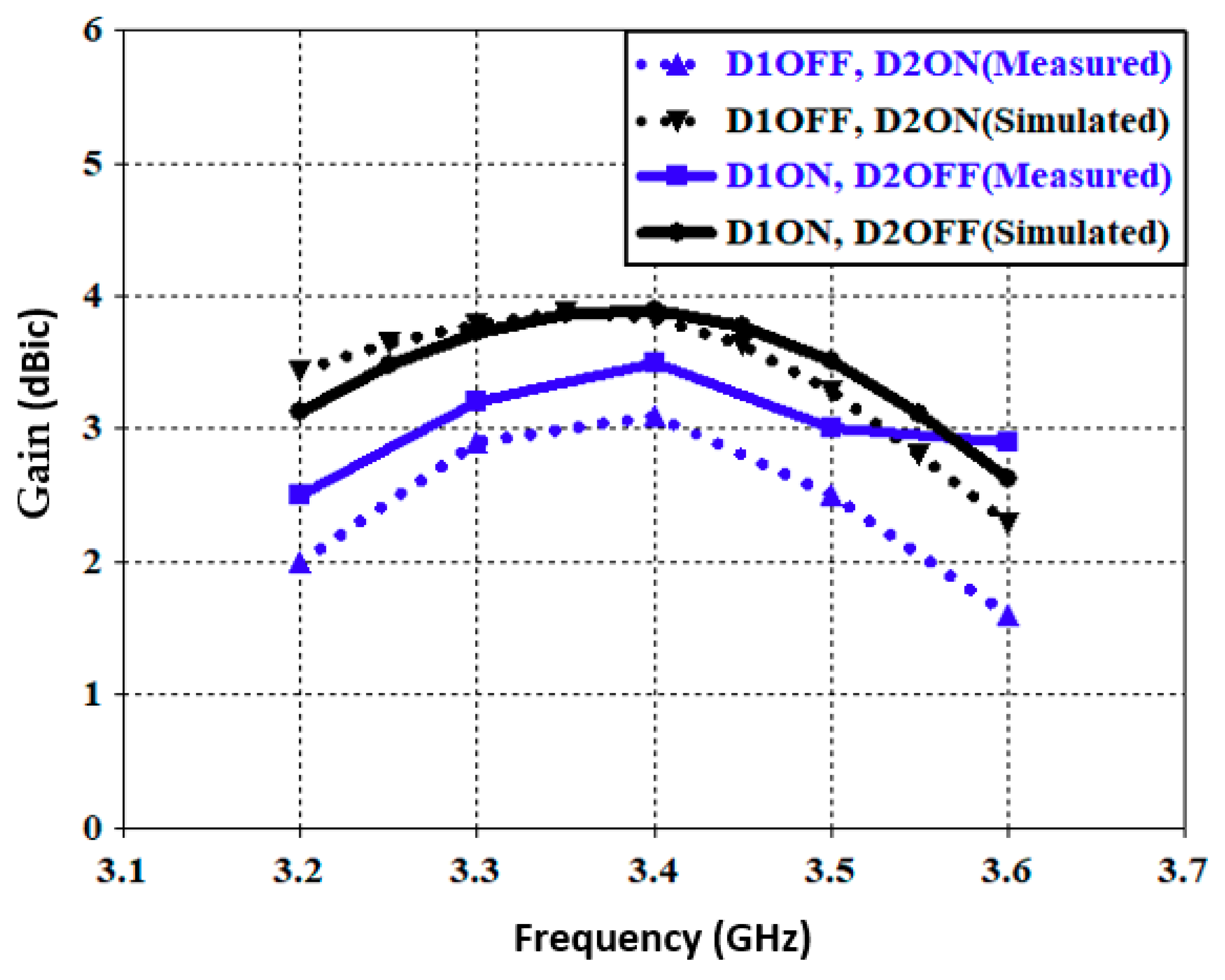
Figure 10 shows the simulated and measured gain, i.e., a maximum of 3.8 dBic for simulated gain in both switching states for the diodes, and measured gain of 3.1 to 3.5 dBic. The discrepancy between the simulated and measured results was attributable to the tolerances of the FR-4 substrate and other factors, such as etching precision, soldering, biasing circuits, and copper thickness.
Table 2 compares this proposed polarization-reconfigurable antenna with other antennas, with similar configurations and performances. The antenna proposed in this study was better than others, with respect to the antenna size, number of switches controlling polarization diversity, and the number of polarization states compared with the design complexity.
4. Conclusions
A circular polarization reconfigurable-microstrip antenna, for use in 5G wireless communications, was designed, modeled, and fabricated. The proposed antenna is reconfigurable for both RHCP and LHCP, by adjusting the DC biasing of two PIN diodes. The proposed design shows a 9.11% fractional bandwidth, with maximum realized gain of (3.1 to 4.8) dBic at 3.5 GHz.
Author Contributions
Conceptualization, Y.I.A.A.-Y. and A.S.A.; methodology, Y.I.A.A.-Y. and A.S.A.; software, Y.I.A.A.-Y. and A.S.A.; validation, Y.I.A.A.-Y., A.S.A., N.O.P., and R.A.A.-A.; formal analysis, Y.I.A.A.-Y., A.S.A., N.O.P., and R.A.A.-A.; investigation, Y.I.A.A.-Y., A.S.A., and R.A.A.-A.; resources, Y.I.A.A.-Y., A.S.A., and R.A.A.-A.; data curation, Y.I.A.A.-Y., A.S.A., and R.A.A.-A.; writing—original draft preparation, Y.I.A.A.-Y., A.S.A., R.A.A.-A., and J.M.N.; writing—review and editing, Y.I.A.A.-Y., A.S.A., R.A.A.-A., and J.M.N.; visualization, Y.I.A.A.-Y., A.S.A., R.A.A.-A., and J.M.N.
Funding
This project has received funding from the European Union’s Horizon 2020 research and innovation programme under grant agreement H2020-MSCA-ITN-2016 SECRET-722424.
Acknowledgments
Authors wish to express their thanks to the support provided by the innovation programme under grant agreement H2020-MSCA-ITN-2016 SECRET-722424 and the Iraqi ministry of higher Education and scientific research.
Conflicts of Interest
The authors declare no conflict of interest.
References
- Elfergani, I.; Rodriguez, A.H.J.; Abd-Alhameed, R. Antenna Fundamentals for Legacy Mobile Applications and Beyond, 1st ed.; Elfergani, I., Rodriguez, A.H.J., Abd-Alhameed, R., Eds.; Springer: New York, NY, USA, 2018. [Google Scholar]
- Hussaini, A.S.; Abdulraheem, Y.I.; Voudouris, K.N.; Mohammed, B.; Abd-Alhameed, R.; Mohammed, H.J.; Elfergani, I.; Abdullah, A.S.; Makris, D.; Rodriguez, J.; et al. Green Flexible RF for 5G. In Fundamentals of 5G Mobile Networks, 1st ed.; Rodriguez, J., Ed.; John Wiley and Sons: Hoboken, NJ, USA, 2015; pp. 241–272. [Google Scholar]
- Al-Yasir, Y.I.A.; Abdullah, A.S.; Mohammed, H.J.; Mohammed, B.; Abd-Alhameed, R.A.; Noras, J. Design of Radiation Pattern-Reconfigurable 60-GHz Antenna for 5G Applications. J. Telecommun. 2014, 27, 7–11. [Google Scholar]
- Bernhard, J. Reconfigurable Antennas; Morgan and Claypool: San Rafael, CA, USA, 2007. [Google Scholar]
- Abdulraheem, Y.I.; Oguntala, G.A.; Abdullah, A.S.; Mohammed, H.J.; Ali, R.A.; Abd-Alhameed, R.A.; Noras, J.M. Design of frequency reconfigurable multiband compact antenna using two PIN diodes for WLAN/WiMAX applications. IET Microw. Antennas Propag. 2017, 11, 1098–1105. [Google Scholar] [CrossRef]
- Nasimuddin, N.; Chen, Z.N. Aperture-coupled asymmetrical c-shaped slot microstrip antenna for circular polarisation. IET Microw. Antennas Propag. 2009, 3, 372–378. [Google Scholar] [CrossRef]
- Lin, W.; Wong, H.; Ziolkowski, R.W. Circularly Polarized Antenna with Reconfigurable Broadside and Conical Beams Facilitated by a Mode Switchable Feed Network. IEEE Trans. Antennas Propag. 2018, 66, 996–1001. [Google Scholar] [CrossRef]
- Hu, J.; Hao, Z. A Compact Polarization-Reconfigurable and 2-D Beam-Switchable Antenna Using the Spatial Phase Shift Technique. IEEE Trans. Antennas Propag. 2018, 66, 4986–4995. [Google Scholar] [CrossRef]
- Statement: Improving Consumer Access to Mobile Services at 3.6 GHz to 3.8 GHz. Available online: https://www.ofcom.org.uk/consultations-and-statements/category-1/future-use-at-3.6-3.8-ghz (accessed on 21 October 2018).
- Boti, M.; Dussopt, L.; Laheurte, J. Circularly polarised antenna with switchable polarisation sense. Electron. Lett. 2000, 36, 1518–1519. [Google Scholar] [CrossRef]
- Su, H.; Shoaib, I.; Chen, X.; Kreouzis, T. Optically tuned polarisation reconfigurable antenna. In Proceedings of the 2012 IEEE Asia-Pacific Conference on Antennas and Propagation, Singapore, 27–29 August 2012; pp. 265–266. [Google Scholar]
- Khidre, A.; Lee, K.; Yang, F.; Elsherbeni, A.Z. Circular Polarization Reconfigurable Wideband E-Shaped Patch Antenna for Wireless Applications. IEEE Trans. Antennas Propag. 2013, 61, 960–964. [Google Scholar] [CrossRef]
- Boonying, K.; Phongcharoenpanich, C.; Kosulvit, S. Polarization reconfigurable suspended antenna using RF switches and P-I-N diodes. In Proceedings of the 4th Joint International Conference on Information and Communication Technology, Electronic and Electrical Engineering (JICTEE), Chiang Rai, Thailand, 5–8 March 2014; pp. 1–4. [Google Scholar]
- Abbas, E.A.; Mobashsher, A.T.; Abbosh, A. Polarization reconfigurable antenna for 5G cellular networks operating at millimeter waves. In Proceedings of the 2017 IEEE Asia Pacific Microwave Conference (APMC), Kuala Lumpur, Malaysia, 13–16 November 2017; pp. 772–774. [Google Scholar]
- Khaleghi, A.; Kamyab, M. Reconfigurable Single Port Antenna with Circular Polarization Diversity. IEEE Trans. Antennas Propag. 2009, 57, 555–559. [Google Scholar] [CrossRef]
- Nishamol, M.S.; Sarin, V.P.; Tony, D.; Aanandan, C.K.; Mohanan, P.; Vasudevan, K. An Electronically Reconfigurable Microstrip Antenna with Switchable Slots for Polarization Diversity. IEEE Trans. Antennas Propag. 2011, 59, 3424–3427. [Google Scholar] [CrossRef]
- Panahi, A.; Bao, X.L.; Yang, K.; O’Conchubhair, O.; Ammann, M.J. A Simple Polarization Reconfigurable Printed Monopole Antenna. IEEE Trans. Antennas Propag. 2015, 63, 5129–5134. [Google Scholar] [CrossRef]
© 2018 by the authors. Licensee MDPI, Basel, Switzerland. This article is an open access article distributed under the terms and conditions of the Creative Commons Attribution (CC BY) license (http://creativecommons.org/licenses/by/4.0/).

 ,
, 


