Article

Comparative Analysis of Two and Four Current Loops for Vector Controlled Dual-Three Phase Permanent Magnet Synchronous Motor

1
School of Electronics, Information and Electrical Engineering (SEIEE), Shanghai Jiao Tong University, Shanghai 200240, China
2
State Grid Corporation of China, Beijing 100031, China
3
State Grid Economic and Technological Research Institute Co., LTD, Beijing 102209, China
4
State Grid Zhejiang Electric Power Co., Ltd., Hangzhou 310007, China
5
Shanghai Huacheng Elevator Technology Co., Ltd., Shanghai 201111, China
*
Author to whom correspondence should be addressed.
Electronics 2018, 7(11), 269; https://doi.org/10.3390/electronics7110269
Submission received: 19 September 2018 / Revised: 10 October 2018 / Accepted: 18 October 2018 / Published: 23 October 2018
(This article belongs to the Special Issue Applications of Power Electronics)

Abstract

:
Dual three-phase (DTP) permanent magnet synchronous motors (PMSMs) are specialized machines which are commonly used for high power density applications. These machines offer the merits of high efficiency, high torque density, and superior supervisor fault tolerant capability compared to conventional three-phase AC-machines. However, the electrical structure of such machines is very complicated, and as such, control becomes challenging. In conventional vector controlled DTP-PMSMs drives, the components of the dq-subspace are associated with electromechanical energy conversion, and two currents, i.e., Id and Iq belonging to this subspace, are used in feedback-loops for control. Such orthodox control methods can cause some anomalies e.g., the voltage source inverter’s (VSI) dead time effect and other nonlinear factors, and can induce large harmonics. These glitches can be greatly alleviated by the introduction of the two-extra current loops to directly control the currents in Z1Z2-subspace in order to suppress the insertion of harmonics. In this paper, two approaches—one with two-current loops and other with four-current loops—for vector controlled DTP-PMSMs are investigated with the aid of different MATLAB-based simulations. Furthermore, in the paper, the influence of additional current loops is quantified using simulation-based results.

1. Introduction

In recent years, governments across the globe have raised the issues of climate changes due to the emission of harmful gases into the atmosphere [1]. The foremost source of these emissions is automobiles, which are running mainly on hydrocarbon fuels. Owing to this fact, the greener aspects of automobiles have increasingly received the attention of governments and the commercial sector. All these aspects have led, in recent times, to important technological advancements in the field of hybrid-electric road vehicles, electric ship propulsion, more electric aircraft, and electric locomotive traction [2,3]. By and large, all transport-related applications necessitate high power density motors, where these motors are principally used as a means of propulsion. Conventional drives systems, which utilize three-phase AC-machinery, are not inevitably the appropriate solution for such applications; due to high power density, dual-three phase PMSMs are used for these purposes [4,5]. Moving forward, these days, AC-machines are fed by inverters, which practically decouple the machine from the mains; thereby, the number phase then cannot be reserved to three phases anymore. Certainly, electrical machines with more than three phases are named multiphase machines, and possess several advantages over three-phase AC-machines. Some of these are discussed in [2,3] and [6,7,8,9], and are briefly reiterated below.
For multi-phase AC-machines, power can be separated into more than three phases, which leads to a reduction in switching current stress. Therefore, the rating requirements of power semiconductor devices can be reduced to a great extent. Thus, the cost of machine drives will be reduced. It must be noted not only that high rating power semiconductor devices are expensive, but also, that they are sometimes not easy to access. Other potential advantages of DTP AC-machines over typical three-phase AC-machines include superior fault tolerance capability, reduced torque pulsations, and improved reliability etc.
Two different topologies of DTP-PMSMs, i.e., symmetric and asymmetric, have frequently been discussed in the literature. A DTP-PMSM utilizes a pair of three-phase windings shifted by 30 degrees and 60 degrees is termed as asymmetric and symmetric winding configurations respectively [10]; both formations are illustrated in Figure 1. The difference between symmetric and asymmetric winding configurations is explained in [11]. Since asymmetric winding arrangements for DTP-PMSMs possess low iron losses and low torque ripple, they have widely been used by researchers. Therefore, for this study, asymmetric winding configuration is considered. Furthermore, there are two circuit topologies which can be used for inverter-fed DTP-PMSMs: one with a single natural (where all six-phases of the machine connected to a single natural point), and another with two isolated natural (where two sets of windings i.e., ACE and BDF are connected separately with two naturals, ACE and BDF represents the six-phases of machine), as depicted in Figure 2.
Theoretical and implementation aspects of both these approaches have been comprehensively explained in [10]. Double natural topology is used for the simulation analyses in this work. Although DTP AC-machines offer several advantages over conventional three-phase AC-machines, their complicated electrical structures can be considered as one of the disadvantages. For VSI-fed DTP drive systems, in practice, six independent currents flow to the machine, which can be viewed as six-dimensional electromechanical structures. Therefore, developing any control structure in the original nature frame for DTP AC-machine is almost impossible. In practice, the control topologies for DTP AC-machines are usually developed in two-dimensional, stationary αβ-frames or two-dimensional, rotating dq-frames instead of reference. Comprehensive details concerning transformations are given in the following section. It is important to mention at this stage that once the machine parameters are altered to an αβ-frame (orthogonal in nature), these parameters are separated into three different subspaces.
These are named the αβ, Z1Z2, and O1O2 subspaces. Among these, only the components linked with αβ-subspaces contribute to electromechanical energy transfiguration, whereas components of the remaining two subspaces can induce large harmonics into machine currents. In conventional vector control for DTP-PMSMs, two currents associated with the αβ-subspace (i.e., Iα and Iβ) are used in feedback loops. But, the inverter dead time effect and other nonlinear factors (e.g., magnetic saturation) can give rise to currents in the Z1Z2 subspace of the machine, resulting in poor harmonics of the phase currents.
In recent investigations by different researchers, a method to suppress the harmonic inclusion implicates the direct control of current in Z1Z2 subspace. For that purpose, two additional current loops for IZ1 and IZ2 are introduced for control [12]. Two approaches of vector control for DTP-PMSMs, one with conventional two current loops and other with unorthodox four current loops, will be the focus of this paper. At first stage, a simulation-based analysis was conducted for both approaches. In the later stages of this paper, brief compression will be done to understand the effectiveness of extra loops and their practical implications for vector control of DTP-PMSMs. Moreover, in [12], an FFT-based (FFT stands for Fast Fourier Transform) analysis current was ignored, which helped us to quantify the influence of additional current loops. In this paper, once the results for both control approaches were obtained, FFT-based analyses were carried out, so that the influence of additional current loops for the purpose of control could be quantified.
The different sections of this paper are organized as follows: Section 2 deals with the theory of space vector decomposition and analytical model of DTP-PMSMs. In Section 3, the theory and implementation of two and four current-loops for vector control are discussed with a brief theoretical background of DTP-SVPWM (space vector pulse width modulation). Comparative analysis of performance for both approaches with the help of simulation-based results are the subject of Section 4; Section 5 concludes this paper.

2. Space Vector Decomposition and Machine Model

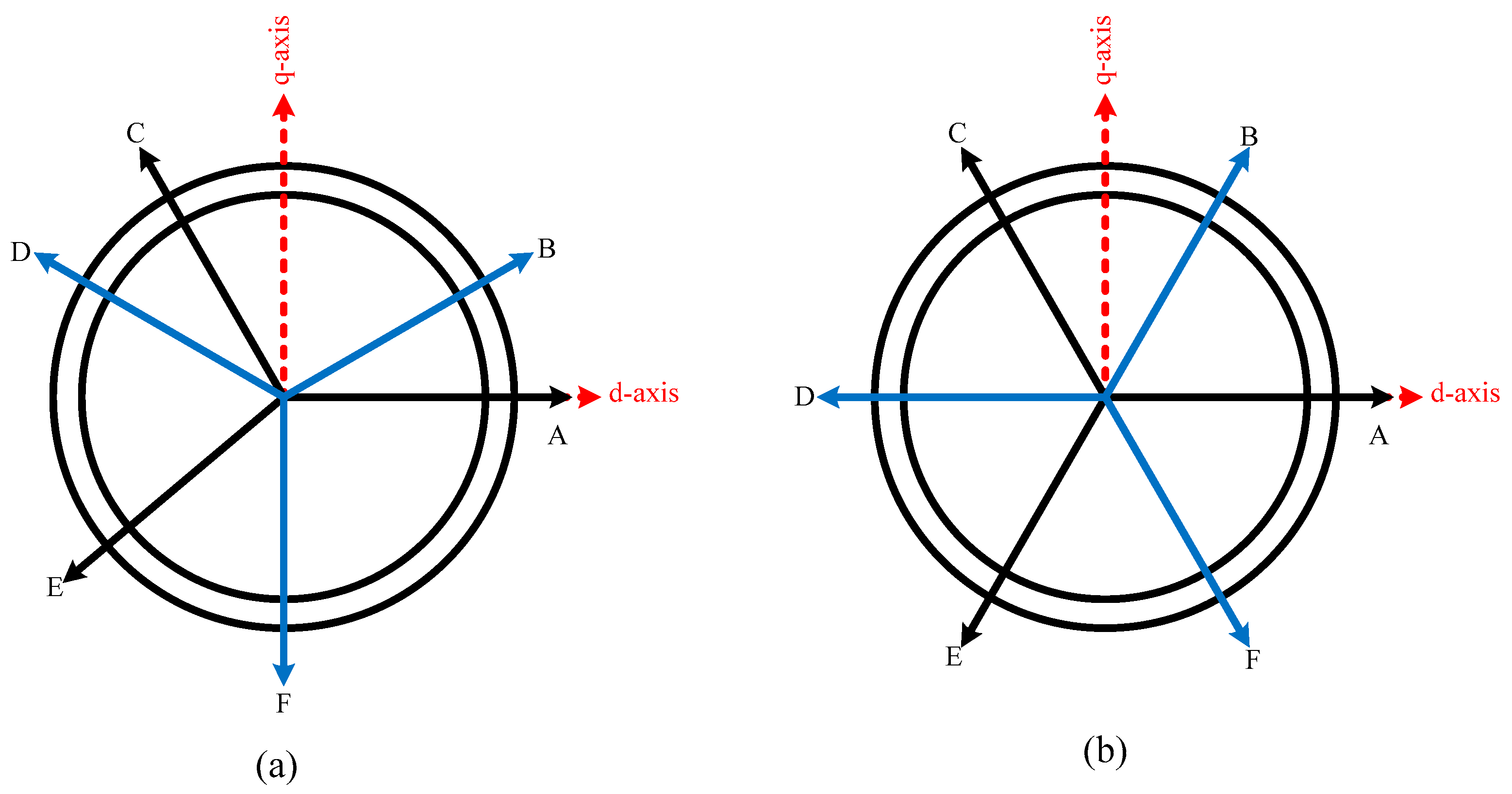
2.1. Space Vector Decomposition

In VSI feed DTP-PMSM, six independent currents can flow into the machine. Owing to this fact, six-phase AC-machines can be viewed as a six-dimensional plane. Consequently, modelling and control of such machines in their original reference frame become a little more complicated. These challenges were greatly alleviated by the introduction of space vector decomposition theory [10]. According to this concept, six-dimensional machine parameters can be transformed into a stationary frame (αβ-frame) which is orthogonal in nature. This transformation procedure chose six vectors from the original nature frame and formed a new basis for six-dimensional space. This transformation can be accomplished by Equation (1).
T 6 S / 2 S = 1 3 [ 1 3 2 1 2 3 2 1 2 0 0 1 2 3 2 1 2 3 2 1 1 3 2 1 2 3 2 1 2 0 0 1 2 3 2 1 2 3 2 1 1 0 1 0 1 0 0 1 0 1 0 1 ]
Once machine parameters have been transformed into the orthogonal frame, they can then be alienated in three subspaces which are referred to as the αβ, Z1Z2, and O1O2 subspaces. Moreover, it is important to mention that the terms linked with αβ-subspace are responsible for electromechanical conversion, while those associated with other subspaces can give rise to harmonics and can cause losses. The transformation matrix retains the following properties: [10]
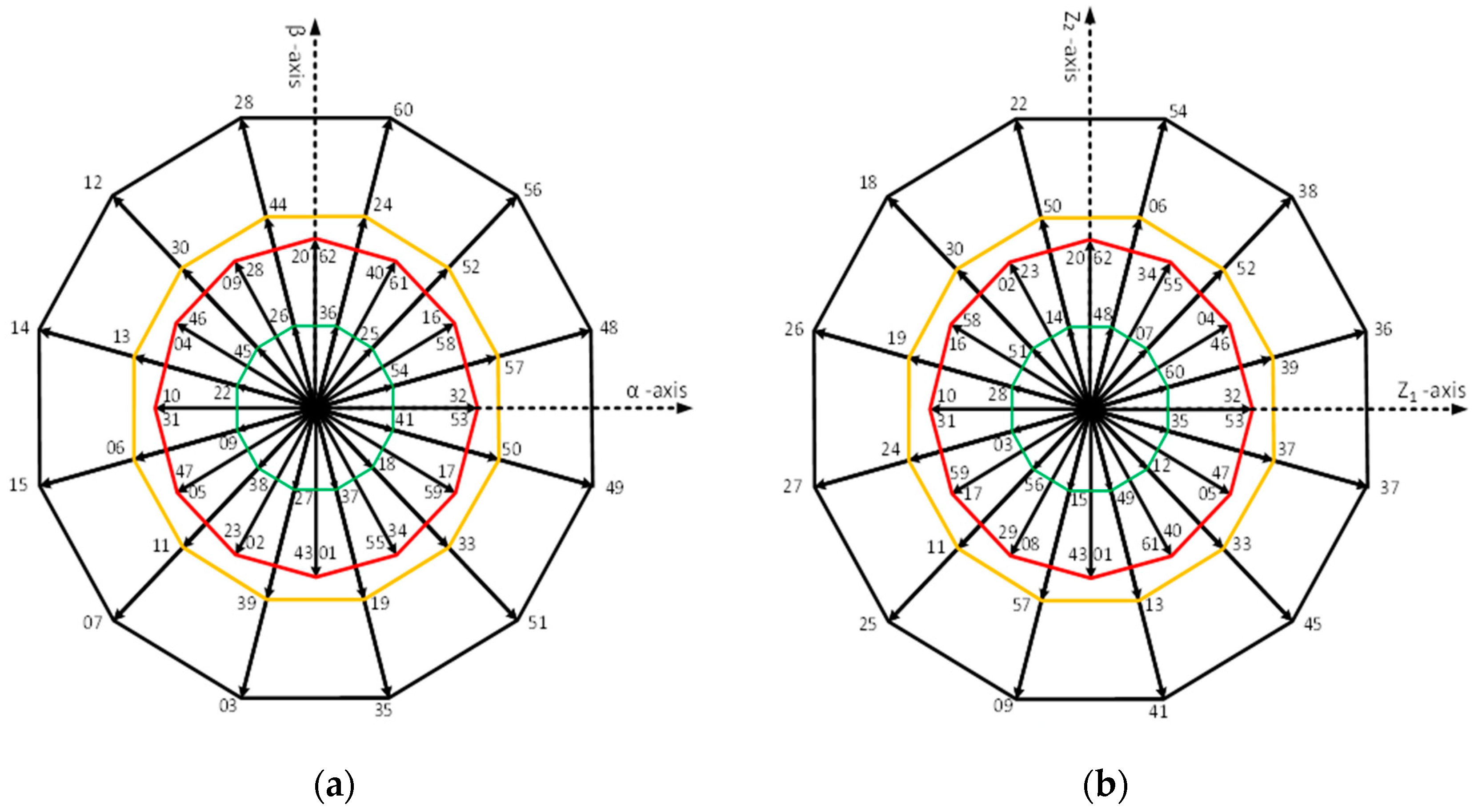
  • Fundamental machine constituents and harmonics of order k = 12m ± 1 where (m = 1, 2, 3......) are mapped on the αβ-plane.
  • Harmonic components with order k = 6m ± 1 where (m = 1, 3, 5......) are mapped into Z1Z2-subspace or on Z1Z2-plane.
  • Harmonic components with order k = 3m where (m = 1, 3, 5......) are mapped into O1O2-subspace or on O1O2-plane. The harmonics components mapped into this plane are considered as non-electromechanical energy conversion components and form the zero-sequence components.

2.2. Machine Model in Stationary Frame

Since the fundamental machine model in the original reference frame is beyond the scope of this paper, it is purposely omitted. Only the machine model in the stationary frame is reported, which is pivotal for developing the vector control of six-phase AC-machines. A set of equations which are used to express the machine model are presented below [6,7,8,13]:
u α = R s i α + L α ( d i α / d t ) + L α β ( d i β / d t ) + k e ω e cos θ
u β = R s i β + L β ( d i β / d t ) + L α β ( d i α / d t ) + k e ω e sin θ
u z 1 = R s i z 1 + L z 1 ( d i z 1 / d t ) + L z 1 z 2 ( d i z 2 / d t )
u z 2 = R s i z 2 + L z 2 ( d i z 2 / d t ) + L z 1 z 2 ( d i z 1 / d t )
u o 1 = R s i o 1 + L o 1 ( d i o 1 / d t )
u o 2 = R s i o 2 + L o 2 ( d i o 2 / d t )
T e = 3 P + [ ψ α i β ψ β i α ]
The specifics of coefficients attached to the above equations are as follows: [ u α u β ] T , [ u z 1 i z 2 ] T and [ u o 1 u o 2 ] T are voltage vectors, likewise [ i α i β ] T , [ i z 1 i z 2 ] T and [ i o 1 i o 2 ] T are the currents vectors in the αβ, Z1Z2, and O1O2 subspaces respectively; Rs is the stator resistance. Other variables include Lα, Lβ, Lz1, Lz2, Lo1, and Lo2, the self-inductance in different subspaces; Lαβ, Lz1z2 and Lo1o2 are the mutual inductance in different subspaces. Moving forward, “P” represents the number of pole pairs and “ψ” represents the flux linkages in the αβ-subspace. It must be observed that the machine model utilized for this project involves stator windings with two isolated neutrals and fed by VSI. Consequently, the vectors of O1O2-subspace are mapped at the origin. As a result, no current flows in the O1O2-subspace, and so the fundamental machine model can be broken down into two sets of decoupled equations which are associated with the αβ and Z1Z2 subspaces. Based on these aspects, it can be concluded that torque and flux components involve only αβ-subspace components, which makes the controlling of DTP machines similar to common three-phase machines. Theoretical explanations of vector control for three-phase motors can be found in [14,15].

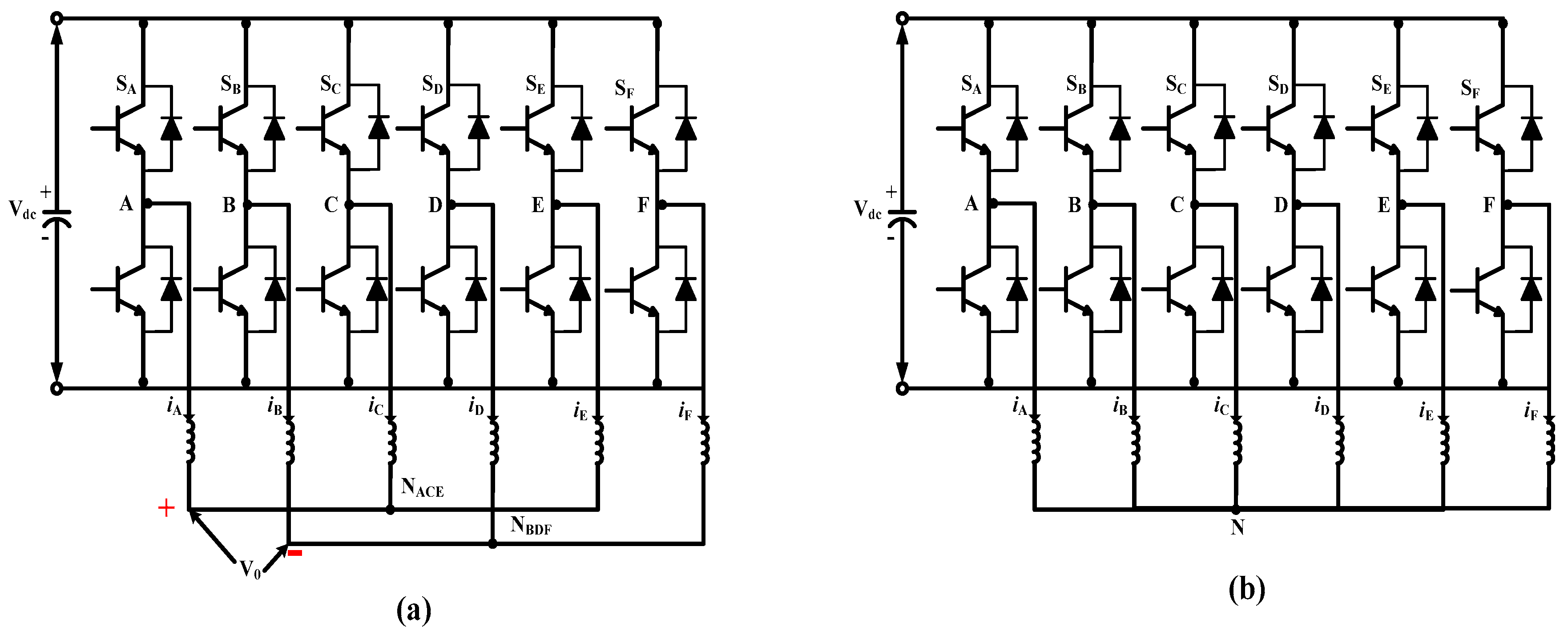
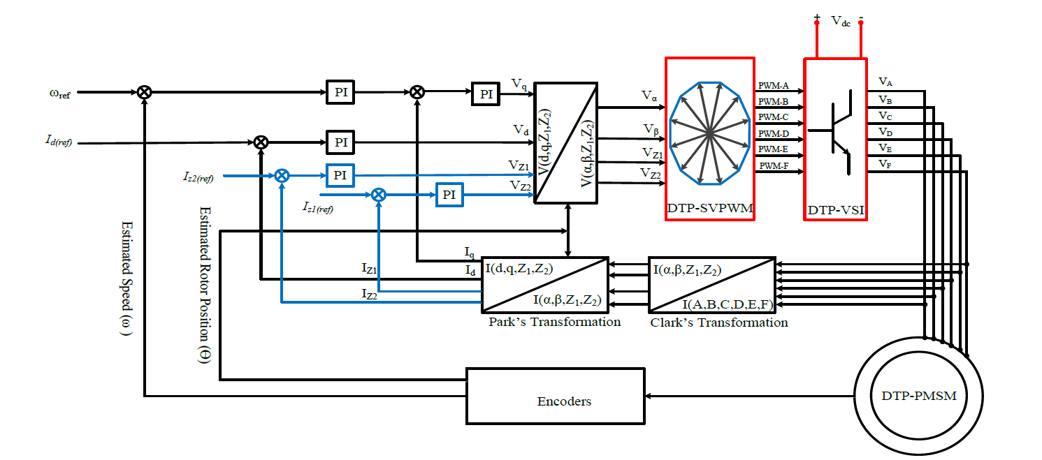
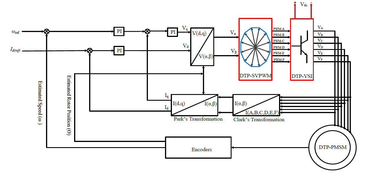
3. Vector Control of Dual-Three Phase PMSMs

To understand the vector control for DTP-PMSMs, it is obligatory to explain the space vector pulse width modulation (SVPWM). In this section of the paper, a modulation scheme for a DTP-SVPWM is comprehensively explained. In a conventional, two-level dual three-phase inverter as shown in Figure 2a, the machine is fed with 26 = 64 inverter voltage vectors; out of those, 60 vectors are active, and 4 vectors, i.e., 0, 21, 42 and 63, are inactive, and are mapped at the origin. These voltage vectors are projected onto the αβ- and Z1Z2-planex; the mapping of voltage vectors on the αβ-plane is described in Figure 3.
Moreover, it must be observed that inverter voltage vectors have different lengths, and the combination of these voltage vectors can be utilized in different modulation schemes. One essential feature for the realization of the modulation scheme is the calculation of vector projections, which are used to determine the dwell time of vectors. The procedure to estimate these projections is highlighted below.
Each vector (shown in Figure 3) is represented by a decimal number, which is converted to a binary number. The most significant bit (MSB) represents the ON or OFF state of IGBT’s associated with phase A; likewise, the second MSB represents phase B and so on. “1’s” indicate that the upper IGBTs associated with any of the phases are ON, and “0’s” indicate that lower IGBTs associated with either phase are ON.
Based on these switching states, the line-to-line voltages against any of the vectors can easily be determined. The line-to-line voltages are then required to be converted into phase voltages using a transformation matrix. Double natural topology for the inverter is used for this project, and the transformation matrix to transform line voltages into phase voltages for this scheme is explained in [10], and reproduced below.
[ u 0 u a u b u c u d u e u f ] = 1 6 [ 2 0 2 0 2 2 2 4 4 2 2 0 2 0 0 4 4 2 2 0 2 2 2 2 2 0 2 0 0 2 2 2 2 0 2 2 2 4 4 0 2 0 0 2 2 4 4 0 2 ] [ u a b u b c u c d u d e u e f 0 0 ]

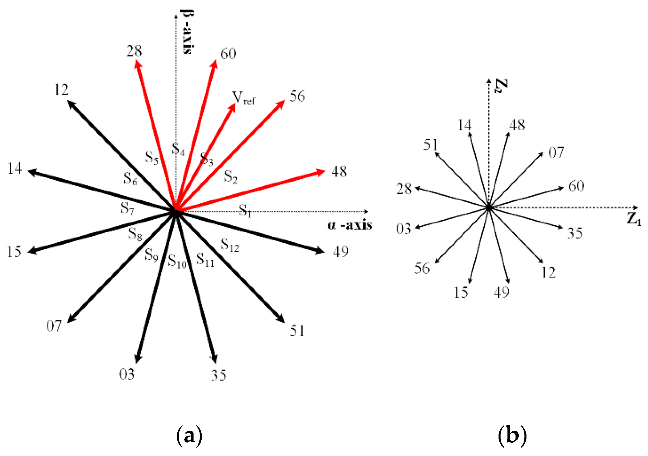
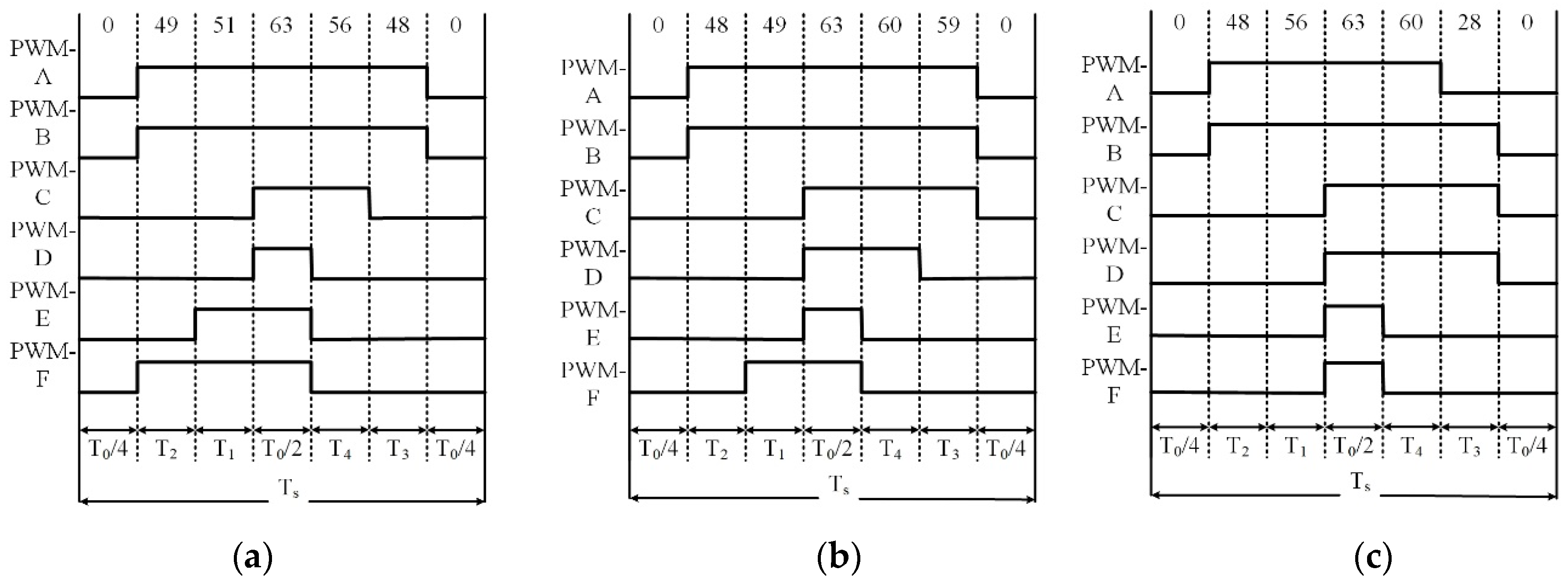
Space Vector PWM Control Strategy

When a machine’s parameters are transferred to orthogonal frame current, voltages vectors in the αβ-subspace will participate in electromechanical energy conversion, as pointed out earlier. So, the objective of PWM control is to synthesize the voltage vectors to fulfil the torque control requirements for the machine while keeping the average volt-sec balance to zero in the other two subspaces.
[ T 1 T 2 T 3 T 4 ] = [ u α 1 u α 2 u α 3 u α 4 u β 1 u β 2 u β 3 u β 4 u z 1 1 u z 1 2 u z 1 3 u z 1 4 u z 2 1 u z 2 2 u z 2 3 u z 2 4 ] 1 [ u α * T s u β * T s 0 0 ]
The space vector topology used for this project was based on the double neutral arrangement, which is explained in the former portion of the paper. It is worthy to note that when stator winding is connected with double neutrals, the projection of vectors on the O1O2-planes is zero. That’s why space vector PWM is performed only on αβ and Z1Z2-planes. The DTP-SVPWM scheme is implemented using Equation (10); for details, see [10]. In Equation (10), V x k is the projection of kth voltage vector on the α-axis on the voltage vector plane in particular subspaces i.e., αβ and Z1Z2, Tk is the dwell time of active vectors, k = 1, 2, 3, 4., and u α * and u β * are reference voltages in αβ-subspace.
The modulation arrangement is described as, in each PWM cycle set of four active voltage vectors must be chosen to ensure that Equation (10) has a unique and positive result. There are many methods to select and place these vectors; in this study, four adjacent voltage vectors are chosen, and have a maximum length in αβ-plane. Suppose that the reference voltage vector resides in sector III as displayed in Figure 4, in this sector, four active vectors, 48, 56, 60, and 28, are used for modulation purposes; these vectors are colored red. It must be observed that together with the four active vectors, two inactive 0 and 63 vectors are also placed in each switching cycle. In this way, six vectors are used for modulation purposes in each PMW cycle. The PWM waveform for a few sectors is exemplified in Figure 5 to clarify the placement of the active and inactive vectors in each switching cycle.

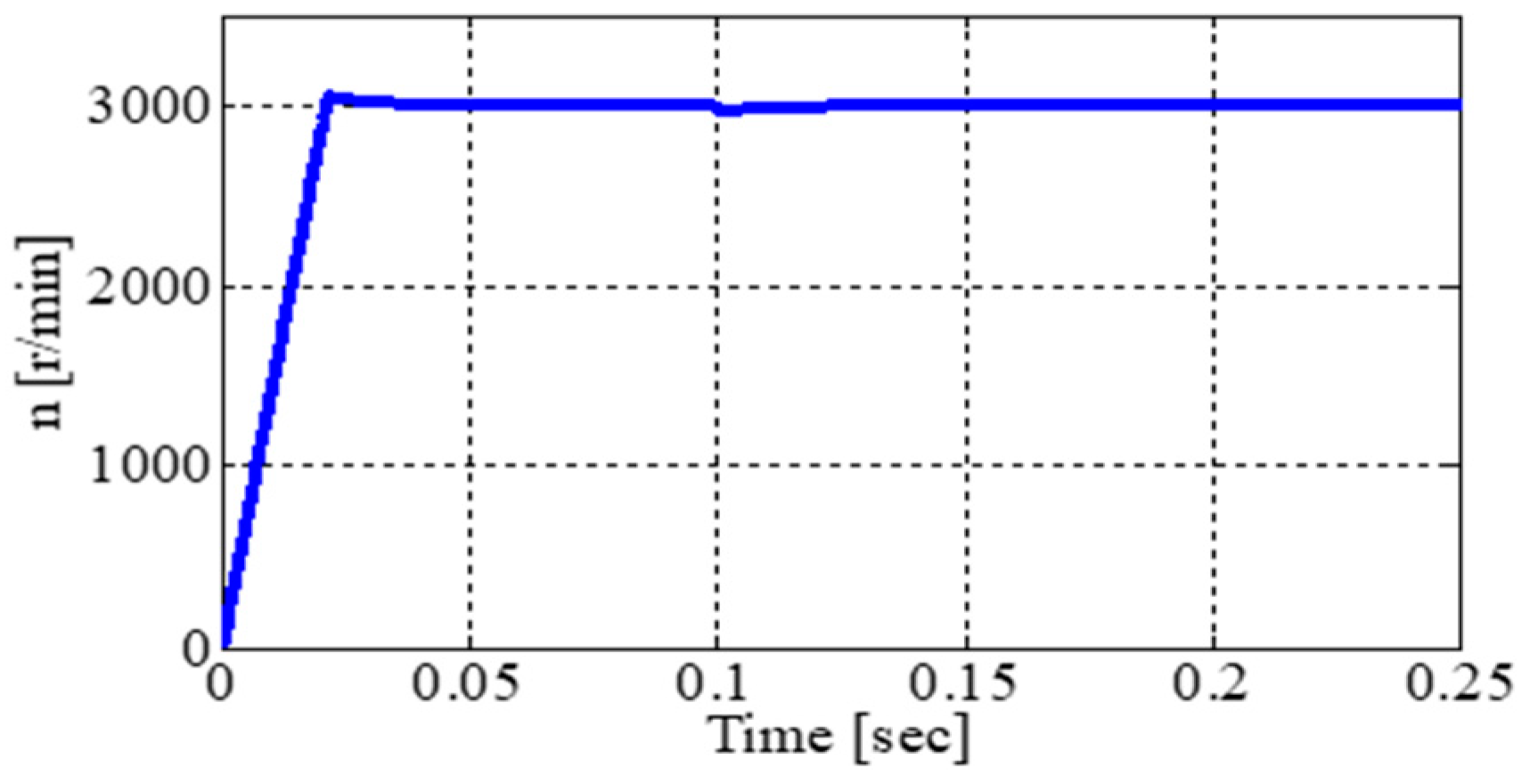
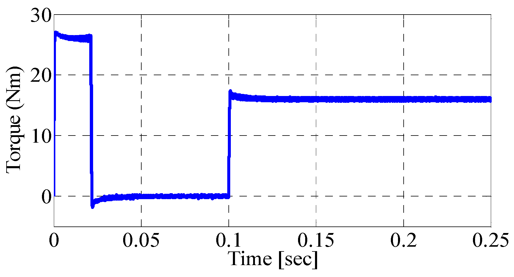
4. The Result of Vector Control for DTP-PMSMs

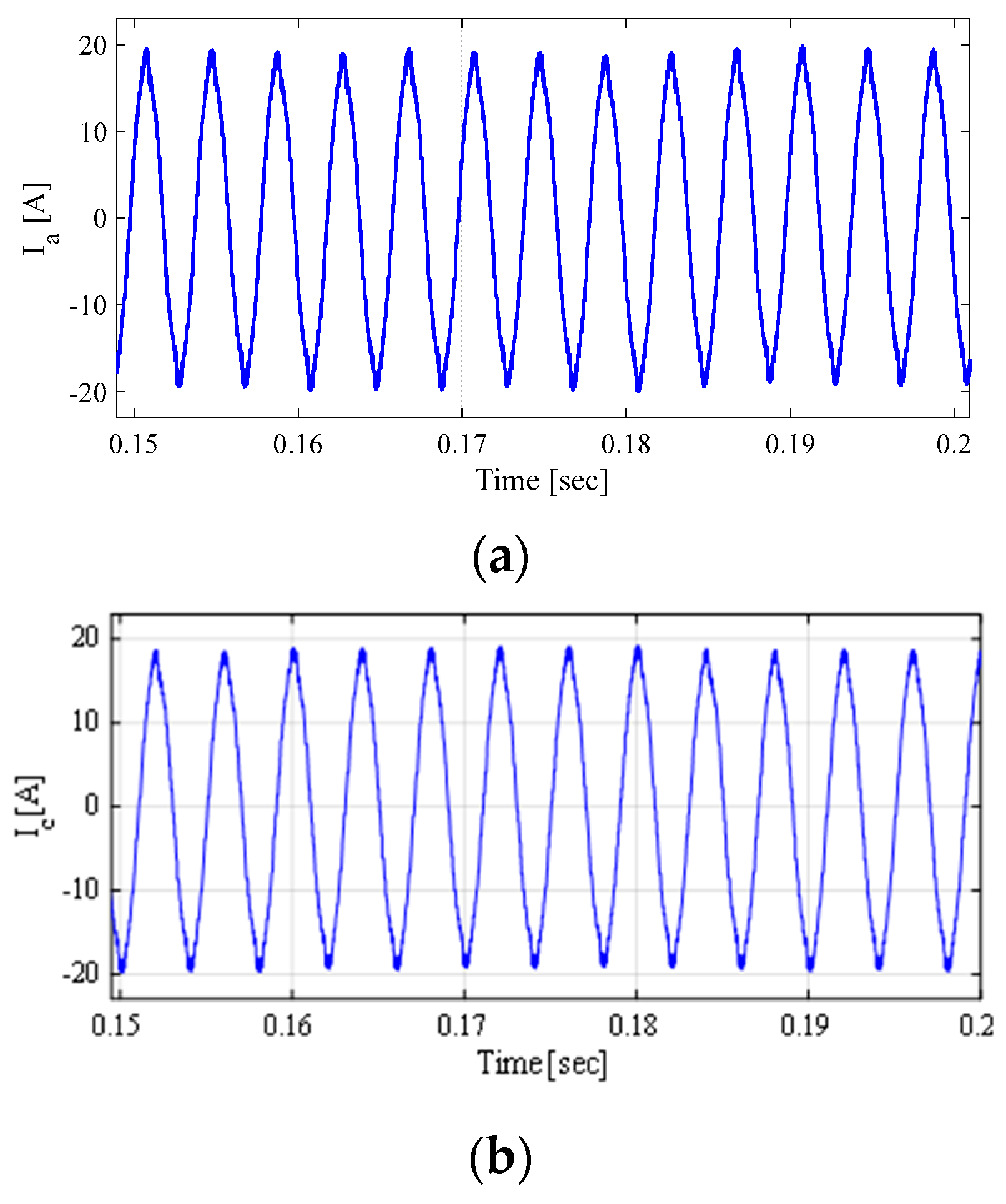
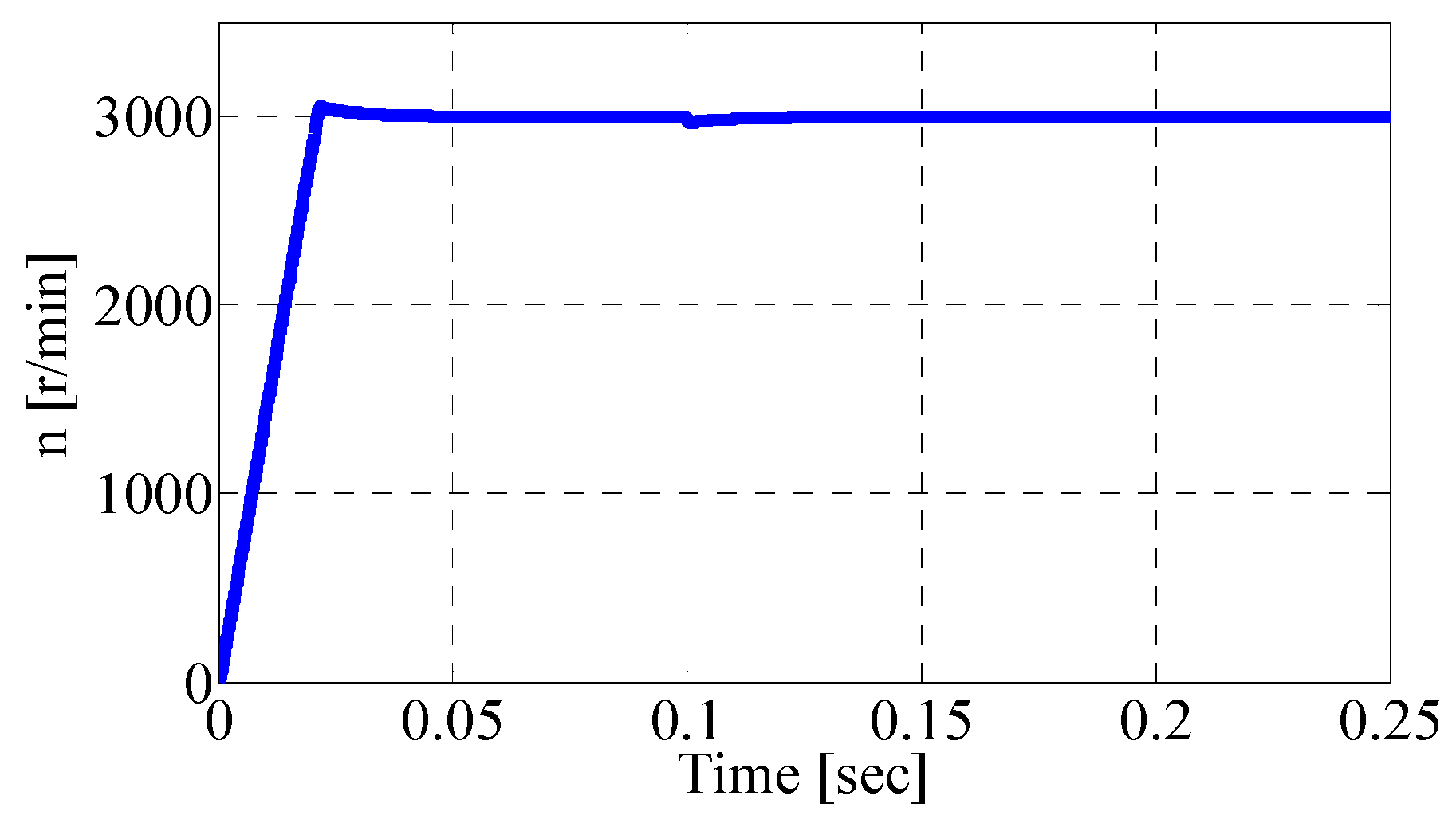
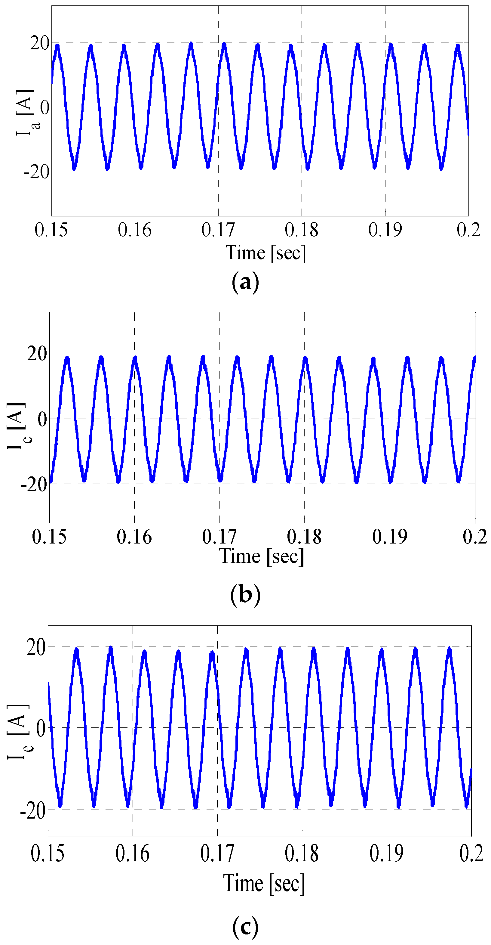
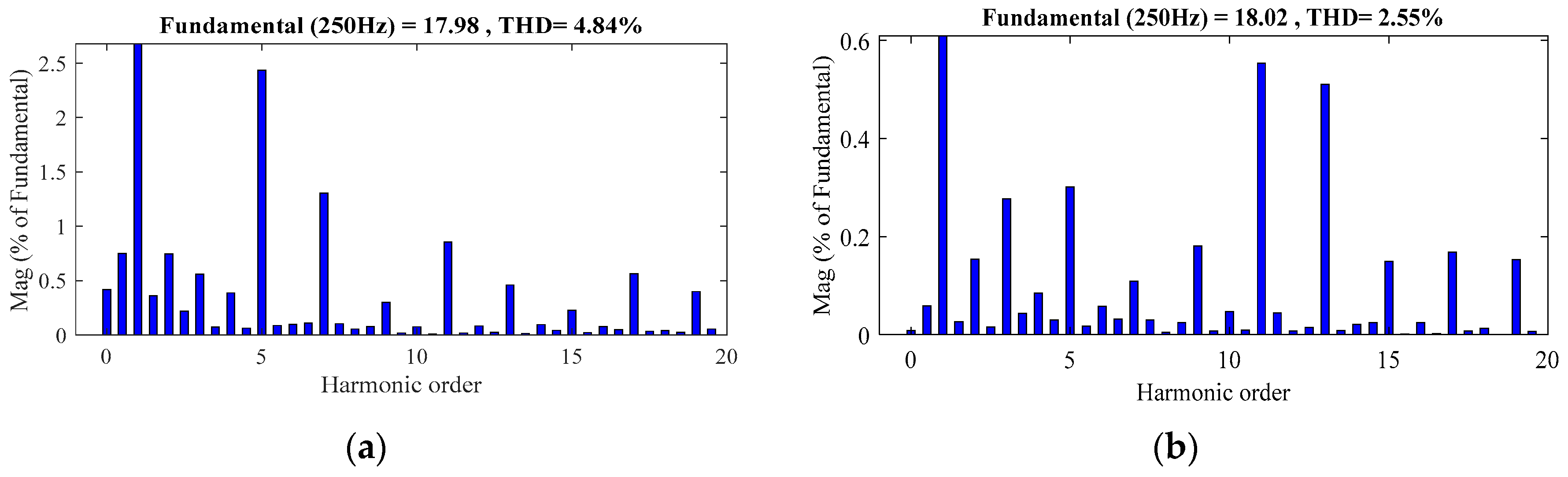
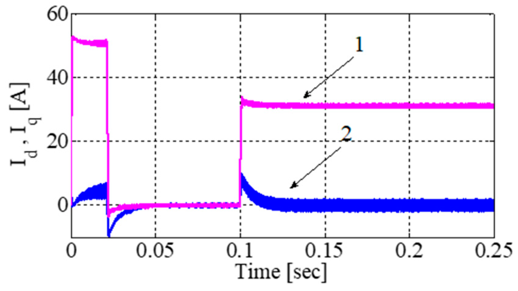
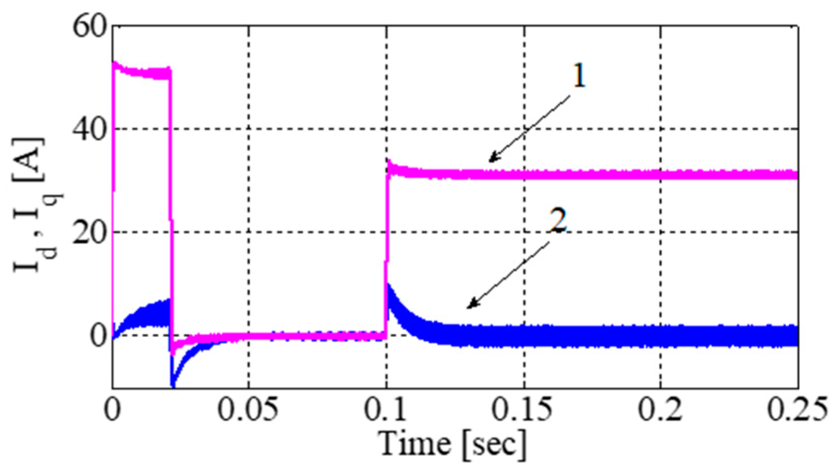
4.1. Two-Loops Current Control of DTP-PMSMs

In usual practice, vector control for DTP-PMSMs is developed and simulated in a two-dimensional stationary (or αβ) frame or two dimensional rotating (or dq) frame, instead of in a nature reference; for particulars see [10]. As discussed earlier, once the machine parameters are transferred to a two dimensional static or rotating frame, only the components of αβ-subspace or dq-subspace participate in electromechanical energy conversion. So, for typical vector control of DTP-PMSMs, the currents of dq-subspace i.e., Id and Iq are used in a feedback loop for good dynamic performance of the machine. The conversion process of parameters from the αβ to dq frame is elaborated in [10].
The schematic diagram for typical vector control with two axes current control is shown in Figure 6. The simulation model was developed based on the block diagram shown in Figure 6, and with consideration of the machine parameters, as discussed in the paper [14], and reproduced in Appendix A, to investigate the performance of the machine under different working conditions. In the first simulation-based experiment, two currents were used in feedback loops under the following conditions: a machine was tested at a rated speed and full load. In this sense, different results were obtained to understand and evaluate the dynamic performance of the machine. In Figure 7, the load currents are shown. In this result, transients at 0.1 s can be observed; the details are as follows. Before reaching to this point, the machine was running at no load. At 0.1 s, a rated load of 16 Nm was applied to the machine, and it started consuming its rated current. In Figure 8 phase currents of winding set ACE are represented. Some supporting results include electromechanical torque and speed, which are portrayed in Figure 9 and Figure 10 respectively. It must be observed that these results were obtained at a rated speed of i.e., 3000 r/min. Moreover, these phase currents elucidated in the Figure 10 were obtained after the application of load and zooming between 0.15 s to 0.2 s.

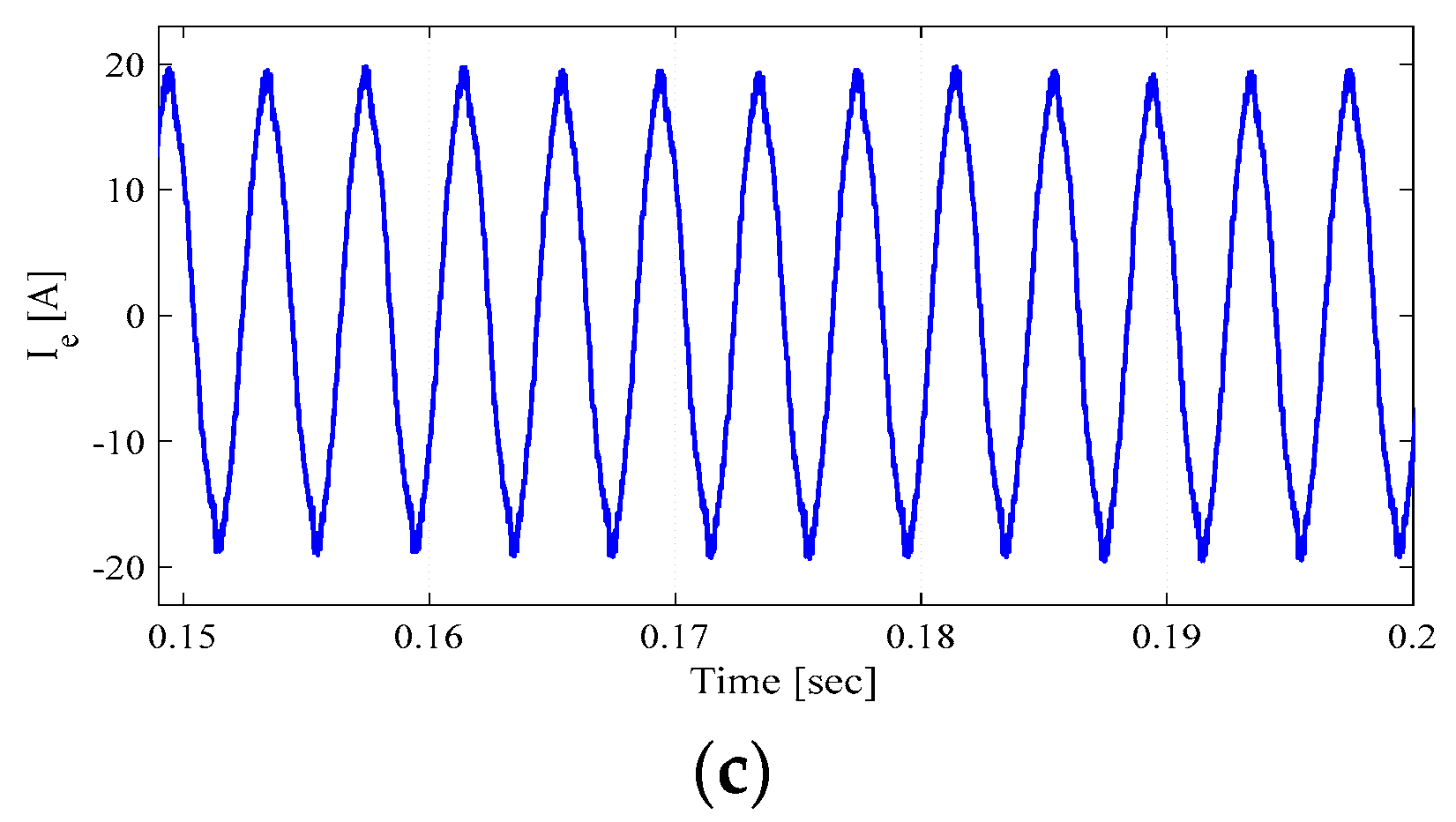
4.2. Four-Loops Current Control of DTP-PMSMs

In two current loop, vector-controlled DTP-PMSMs, the problems associated with harmonics is encountered indirectly by ensuring that the average current of Z1Z2-subspace is zero. But due to the inverter’s or the machine’s asymmetry, this problem cannot be fully eradicated, and certainly can cause a large harmonic current to flow through the machine; it could be the cause of increased losses as well [12]. Some of the problems due to Z1Z2-subspace are briefly discussed in [16].
In recent years different authors have proposed different approaches to mitigate these challenges. One such solutions introducing two extra current loops is reported in [12]. These extra current loops are introduced for the currents of Z1Z2-subspace, i.e., IZ1 and IZ2 are put into the closed feedback loops and controlled by the conventional PI controllers. The control diagram for four loops control is described in Figure 11. Based on the arrangement depicted in Figure 11, a Matlab-based simulation was built, and four loop control was verified. Similar parameters (as discussed for two-loops) under the influence of four loop current control were used, and the results are highlighted in this section of the paper. Figure 12 represents the load currents; it can be observed from the result that Id was set to zero, and also, at 0.1 s, rated torque was applied to the machine and it started taking the rated current. Some supporting results include the electromechanical torque and speed represented by Figure 13 and Figure 14 respectively. Likewise, in Figure 15, the phase currents of winding set ACE were obtained. It must also be observed that these results are obtained at full load and rated speed.
Finally, an FFT analysis of phase current A was conducted under the influence of two and four current loops, to observe the harmonics performance of machine. The FFT analysis of phase current A is depicted in Figure 16.

5. Conclusions

Conventional two current loops vector control and recently-developed four current loops vector control for DTP-PMSMs are discussed in this paper. The theoretical and implementation aspects of both approaches were elaborated in comprehensive detail. Different results for both control structures at the rated speeds of the machines were obtained to assess the accuracy of the control algorithms. The following points conclusions on the simulation analysis of both control methodologies can be made: In conventional, two-current control loops methods, the modulation scheme is adopted in such a way that the average volt/sec balance in each PWM cycle remains zero on the Z1Z2 and O1O2 subspaces. However, the Z1Z2-subspace of the machine contains stator resistance and leakage inductance, for to this reason, low-level voltage harmonics can be induced to the machine, and as a result, high-level of harmonics can be induced in the phase currents. Therefore, instead of controlling the currents indirectly for the Z1Z2-subspace by making sure the volt/sec balance equal to zero, an additional two loops were added so that direct control of currents in Z1Z2-subspaces can be achieved. The additional two-current loops for Z1Z2-subspaces of machines can be used to reduce the level of harmonics in the phase currents. Harmonics analyses of both approaches were presented in the results, which indicated that the addition of two extra currents loops can improve the harmonics in phase currents. The inclusion of additional current loops also improves torque ripple, but will have no influence on the average value of torque. In terms of hardware implementation, four current loops have some drawbacks as well. The addition of two extra loops can increase the overall cost of the prototype. Moreover, extra loops also complicate the overall hardware structure.

Author Contributions

M.A., Z.W. (Zhixin Wang) and C.W. proposed the idea for this paper. The author M.A. was involved in designing this study and also done the simulation work. The simulation work was analyzed and verified by Z.W. (Zhixin Wang) and C.W. The authors S.Y., Z.W. (Zhidong Wang), C.Z., and H.Q. provided their valuable input for relevant literature need to be discussed in the paper and also helped in writing the introductory part of paper. Major portion of this paper was written by the author M.A. under the supervision of Z.W. (Zhixin Wang) and C.W. and at the final stage, paper was comprehensively reviewed by all authors.

Funding

Authors would like to acknowledge the following agencies for their support: Project Supported by State Grid Science & Technology: Research on Morphologies and Pathways of Future Power Systems(B3440818K010); Special Funding of Technical Standard of Shanghai Science and Technology Commission (18DZ2205700); Project of Science and Technology Project of Minhang District of Shanghai (2017MH271).

Conflicts of Interest

The authors declare no conflicts of interest.

Appendix A

Table A1. DTP-PMSM Specifications.
ParameterValue
Power Rating5 kW
Speed Rating3000 r/min
Torque Rating 16 Nm
Pole Pairs5
Stator Resistance0.0495 Ω
Ld, Lq2.4633 mH, 2.4733mH
Leakage Inductance 1.5207 mH

References

  1. Tong, C.; Zheng, P.; Wu, Q.; Bai, J.; Zhao, Q. A brushless claw-pole double-rotor machine for power-split hybrid electric vehicles. IEEE Trans. Ind. Electron. 2014, 61, 4295–4305. [Google Scholar] [CrossRef]
  2. Levi, E. Multiphase electric machines for variable-speed applications. IEEE Trans. Ind. Electron. 2008, 55, 1893–1909. [Google Scholar] [CrossRef]
  3. Levi, E.; Barrero, F.; Duran, M.J. Multiphase machines and drives-revisited. IEEE Trans. Ind. Electron. 2016, 63, 429–432. [Google Scholar] [CrossRef]
  4. Pisek, P.; Stumberger, B.; Marcic, T.; Virtic, P. Design analysis and experimental validation of a double rotor synchronous PM machine used for HEV. IEEE Trans. Magn. 2013, 49, 152–155. [Google Scholar] [CrossRef]
  5. Dalal, A.; Ansari, M.N.; Kumar, P. A novel steady-state model of a hybrid dual rotor motor comprising electrical equivalent circuit and performance equations. IEEE Trans. Magn. 2014, 50, 1–11. [Google Scholar] [CrossRef]
  6. Ren, Y.; Zhu, Z.-Q. Enhancement of steady-state performance in direct-torque-controlled dual three-phase permanent-magnet synchronous machine drives with modified switching table. IEEE Trans. Ind. Electron. 2015, 62, 3338–3350. [Google Scholar] [CrossRef]
  7. Almarhoon, A.H.; Ren, Y.; Zhu, Z. Sensorless switching-table-based direct torque control for dual three-phase PMSM drives. In Proceedings of the 2014 17th International Conference on Electrical Machines and Systems (ICEMS), Hangzhou, China, 22–25 October 2014. [Google Scholar]
  8. Bojoi, R.; Lazzari, M.; Profumo, F.; Tenconi, A. Digital field-oriented control for dual three-phase induction motor drives. IEEE Trans. Ind. Appl. 2003, 39, 752–760. [Google Scholar] [CrossRef]
  9. Parsa, L. On advantages of multi-phase machines. In Proceedings of the 2005 31st Annual Conference of IEEE Industrial Electronics Society (IECON 2005), Raleigh, NC, USA, 6–10 November 2005. [Google Scholar]
  10. Zhao, Y.; Lipo, T.A. Space vector PWM control of dual three-phase induction machine using vector space decomposition. IEEE Trans. Ind. Appl. 1995, 31, 1100–1109. [Google Scholar] [CrossRef]
  11. Zheng, P.; Wu, F.; Lei, Y.; Sui, Y.; Yu, B. Investigation of a novel 24-slot/14-pole six-phase fault-tolerant modular permanent-magnet in-wheel motor for electric vehicles. Energies 2013, 6, 4980–5002. [Google Scholar] [CrossRef]
  12. Changpan, Z.; Jianyong, S.; Guijie, Y.; Nianwei, X. Four-dimension current vector control for dual three-phase PMSM. In Proceedings of the 2014 17th International Conference on Electrical Machines and Systems (ICEMS), Hangzhou, China, 22–25 October 2014. [Google Scholar]
  13. Ahmad, M.; Zhang, W.; Gao, Q. Low and zero speed position estimation of dual three-phase PMSMs based on the excitation of PWM waveforms. In Proceedings of the 2017 IEEE 3rd International Future Energy Electronics Conference and ECCE Asia (IFEEC 2017—CCE Asia), Kaohsiung, Taiwan, 3–7 June 2017. [Google Scholar]
  14. Yano, M.; Abe, S.; Ohno, E. History of power electronics for motor drives in Japan. In Proceedings of the 2004 IEEE Conference on the History of Electronics, Bletchley Park, Bletchley Town, UK, 28–30 June 2004. [Google Scholar]
  15. Vas, P. Sensorless Vector and Direct Torque Control; Oxford University Press: Oxford, UK, 1998. [Google Scholar]
  16. Che, H.S.; Levi, E.; Jones, M.; Hew, W.-P.; Rahim, N.A. Current control methods for an asymmetrical six-phase induction motor drive. IEEE Trans. Power Electron. 2014, 29, 407–417. [Google Scholar] [CrossRef]
Figure 1. This figure represents the Winding configuration dual three-phase (DTP) AC-machines: (a) Asymmetric configuration; (b) Symmetric configuration.
Electronics 07 00269 g001
Figure 2. This figure symbolizes the winding configurations of inverter fed DTP-PMSM (permanent magnet synchronous motor): (a) Double neutral topology; (b) Single neutral topology.
Electronics 07 00269 g002
Figure 3. Projection of voltage vectors: (a) On αβ-plane; (b) On Z1Z2-plane.
Electronics 07 00269 g003
Figure 4. Projection of vectors used for modulation. (a) On αβ-plane and (b) On Z1Z2-plane.
Electronics 07 00269 g004
Figure 5. PWM waveforms for all phases: (a) Sector I; (b) Sector II and (c) Sector III.
Electronics 07 00269 g005
Figure 6. Block diagram of vector control with two-axis current control.
Electronics 07 00269 g006
Figure 7. Load current; (1) Iq and (2) Id (measured in amperes).
Electronics 07 00269 g007
Figure 8. Phase currents of winding set ACE; (a) Phase current “A” measured in amperes; (b) Phase current “C” measured in amperes and (c) Phase current E measured in amperes.
Electronics 07 00269 g008aElectronics 07 00269 g008b
Figure 9. Electromechanical torque.
Electronics 07 00269 g009
Figure 10. Speed (measured in r/min).
Electronics 07 00269 g010
Figure 11. Block diagram of vector control with four-axis current control.
Electronics 07 00269 g011
Figure 12. Load current (1) Iq and (2) Id.
Electronics 07 00269 g012
Figure 13. Electromechanical torque.
Electronics 07 00269 g013
Figure 14. Speed (measured in r/min).
Electronics 07 00269 g014
Figure 15. Phase currents of winding set ACE; (a) Phase current “A” measured in amperes; (b) Phase current “C” measured in amperes and (c) Phase current E measured in amperes.
Electronics 07 00269 g015
Figure 16. FFT Analysis of phase current A: (a) with two loops current control (b) with four loops current control.
Electronics 07 00269 g016

