Article

Reliability of Variable Speed Pumped-Storage Plant

1
Power Electronics Laboratory, Department of Electrical and Computer Engineering, Ajou University; Suwon 443749, Korea
2
Hydropower Simulation Laboratory, Department of Water Resources Development and Management, Indian Institute of Technology Roorkee, Roorkee 247667, India
*
Author to whom correspondence should be addressed.
Electronics 2018, 7(10), 265; https://doi.org/10.3390/electronics7100265
Submission received: 20 September 2018 / Revised: 18 October 2018 / Accepted: 19 October 2018 / Published: 22 October 2018
(This article belongs to the Special Issue Renewable Electric Energy Systems)

Abstract

:
The multi-channel (MC) back-to-back voltage source inverter (VSI)-fed doubly fed induction machine (DFIM) is emerging as a highly interesting topic in large-rated variable speed pumped-storage power plants (PSPP) in view of cost, optimal efficiency, and space requirements. Although the VSI is the fundamental part of the drive controlling the active/reactive power of the plant, redundancy is presently not adopted in practice causing the unit as a whole to shut down upon a failure in the converter and control circuit. This paper evaluates a large-rated (250 MW) DFIM-fed variable-speed unit of a PSPP in terms of its reliability and availability. A Markov model is developed to assess the reliability of the drive based on a number of factors including survivability and annual failure rate (FIT). Further, the Markov model is applied to different PSPPs for comparison of reliability among them.

1. Introduction

Several energy storage technologies have been developed including compressed air, pumped-storage power plant (PSPP), flywheels, high energy batteries, super capacitors, biofuels, and thermal energy storage. Among these, the PSPP is a mature technology in the category of large energy storage systems and is critical for power system flexibility [1]. To comply with the Kyoto protocol, worldwide focus is on renewable energy sources like wind, solar, etc.; however, renewable energy generation is highly variable and intermittent in nature affecting the power system operations, especially power balancing; therefore, power grid operators are encouraged to connect the energy storage systems to the power system network. In addition, European countries have introduced regulations for stabilizing the power grid network wherein ‘energy storage systems are mandatory when more than 20% of the power is generated using solar and wind’ [2].
Since the 1900s, synchronous machine-based fixed-speed PSPPs have been installed in European, American, and Asian continents, and more than 110 GW of them are in active operation worldwide [3,4]. Nowadays, variable speed PSPP is an emerging technology used in pumped-storage systems where it offers several benefits, specifically (i) increased efficiency in generation/pumping mode irrespective of water level in the dam, (ii) mode transition from pumping to generation and vice versa in short time, (iii) high dynamic stability against grid and speed fluctuations, (iv) high ramp rate compared to fixed-speed PSPP, (v) quick response in load balancing, and (vi) flywheel effect (inertia energy) [5], etc. Variable speed PSPP was introduced in Japan in the early 1990s, and 18 PSPPs (i.e., 36 units) are installed/under construction worldwide with a total capacity of 9.425 GW [4,6].
The synchronous machine-based variable speed PSPPs (e.g., 100 MW Grimsel 2 at Switzerland) [7] installed in various countries offer several benefits; however, this system is not yet accepted by the project authorities due to its limitations as listed here: (i) power converter with a rating similar to the machine is required, which is unfeasible due to the larger size (space requirement) and cost, especially in the case of an underground power house, (ii) hydro turbine requires only 10–15% speed variation from the rated speed for significant improvement in efficiency; therefore, focus is shifted to doubly fed induction machine (DFIM) for use in variable speed PSPP (400 MW Ohkawachi PSPP, Japan (1993); 250 MW Linthal PSPP, Switzerland (2015); 250 MW Tehri PSPP, India (under construction)), where power converters with a capacity lower than the rating of the machine are enough to achieve the required efficiency improvement and high dynamic stability [8,9].
Power converters connected on the rotor side of the DFIM ensures active and reactive power control for the drive. Since the 1990s, cycloconverters (e.g., 400 MW Ohkawachi PSPP, Japan (1993)) have been used on the rotor side of DFIM; however, they are now being phased out gradually due to high ripples in rotor current and reactive power consumption from grid (rotor side). Presently, the three-level back-to-back voltage source inverter (VSI) is preferred owing to its less THD and unity power factor on grid side (rotor). In the case of a large current on rotor side, multi-channel (MC) power converters are adopted, e.g., the five-channel, three-level back-to-back VSI (connected on rotor side) at 250 MW Tehri PSPP, India [10] that handles 11,600 A.
It is reported that redundancy in power converter with control circuit is not yet adopted in multi-channel DFIM-fed drives in industries, especially in pumped-storage units, due to the operational challenges [11,12]. Also, faults are more likely in power converters of variable speed drives causing frequent plant shutdowns and huge generation losses [13]; therefore, redundancy in power converters and control circuits, especially in pumped-hydro applications of large rating (>100 MW), is expected to be imposed as a statutory requirement by the regulatory body, e.g., Central Electricity Authority (CEA) of India (2007) [14]. This creates uncertainties in decision-making for the policy makers and project authorities of the variable speed PSPP in view of reliability and availability of the unit.
Considerable research has been conducted in doubly fed induction machine drives with regard to motor control [15,16] grid disturbances, converter faults, sensor failures, fault detection, fault tolerant control, etc. [17,18,19,20,21,22,23]. Particularly, references [17,18] discuss the impact of the VSI faults on induction drives. Likewise, faults in power converter, control circuits, and motor are detailed in [19,20]. Grid disturbances such as the unbalanced grid voltage and voltage sag are discussed in [21,22,23]. Reliability of supply, motor, and components are analyzed in [24,25,26,27] for squirrel-cage induction and synchronous machine drives. Several publications discussed the reliability assessment techniques such as fault trees, Markov model, reliability block diagrams, etc., that are discussed in detail in [28]. The Markov model is considered as the most powerful technique with better features such as (i) fault coverage, (ii) time-dependent failure rates, (iii) common mode failures, etc. compared to the fault trees and reliability block diagrams.
Reliability analysis is critical for effective development, maintenance, and operation of large-rated variable speed PSPPs. Figure 1 shows the single line diagram of a 250-MW DFIM-fed variable-speed unit consisting of multi-channel VSI, control system, DFIM, phase shift transformer, unit transformer, inter phase reactors, etc. In this study, we analyze the reliability and availability of this system using Markov model in comparison with fixed-speed PSPP.
The rest of this paper is structured as follows. Section 2 discusses the survivability of the test unit (250 MW DFIM) with regard to the converters, sensors, and rotor winding failures. The Markov reliability model and equations are detailed in Section 3. The reliability components of a 250-MW variable-speed unit are presented in Section 4, and the reliability estimation and comparative analysis are discussed in Section 5. Finally, the concluding remarks are presented in Section 6.

2. Survivability Analysis of a 250-MW Variable-Speed Unit

This section discusses the survivability status of the 250-MW DFIM-fed variable-speed unit [29] with regard to power converters, sensors, and rotor winding faults. A 250-MW DFIM with five-channel three level neutral point back-to-back converter (3L-NPC) is designed in Matlab/Simulink tool to observe the drive behavior. A field-oriented vector control system is designed to control the active (real)/reactive power of the unit, and an active current sharing control is embedded in the controller for proper sharing of rotor currents among the converters. The detailed control circuit and equations are detailed in [29]. Faults are simulated in the system using the multi-port switch and breaker in Matlab/Simulink. The switching frequencies of the grid-side and machine-side converters are selected as 500 Hz and 300 Hz, respectively, considering the switching losses.
The active and reactive powers of the 250-MW DFIM at normal operating condition are shown in Figure 2. Stator current of the machine is shown in Figure 2c. It is inferred that magnitude of the stator current changes with respect to the change in real and reactive power delivery, and frequency of the stator current is constant at grid frequency. In case of rotor currents, both magnitude and frequency are changed (shown in Figure 2e). Frequency of the rotor currents depends on slip frequency. In addition, it is noted that the rotor voltage also depends on the slip of the machine. In the case of faults, the machine is instructed to operate at 0.96 p.u. (221.5 rpm), and the shaft power is considered as 240 MW. Furthermore, the power factor is set as 0.95 through the reactive power control system. The test results show that: (i) the line current in stator winding is 9157 A (0.814 p.u.), (ii) the voltage (P-P) applied to the rotor winding by the rotor-side converter is 1255 V (0.38 p.u.), (iii) the line current in rotor winding is 10,360 A (0.893 p.u.), (iv) the reactive power consumption of the machine is 15.3 MVAr (0.05 p.u.), and (v) the frequency of rotor current is 2 Hz.

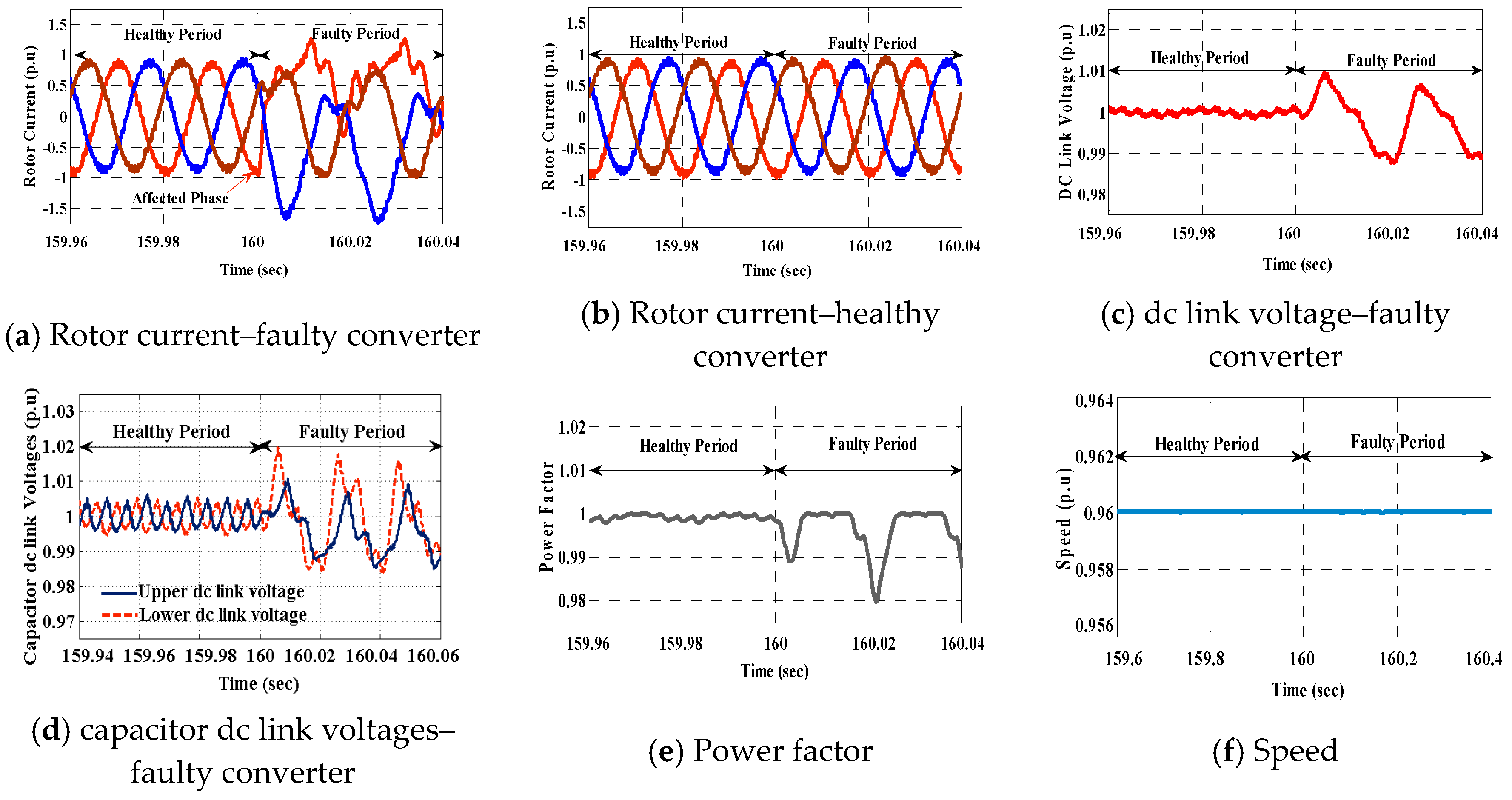
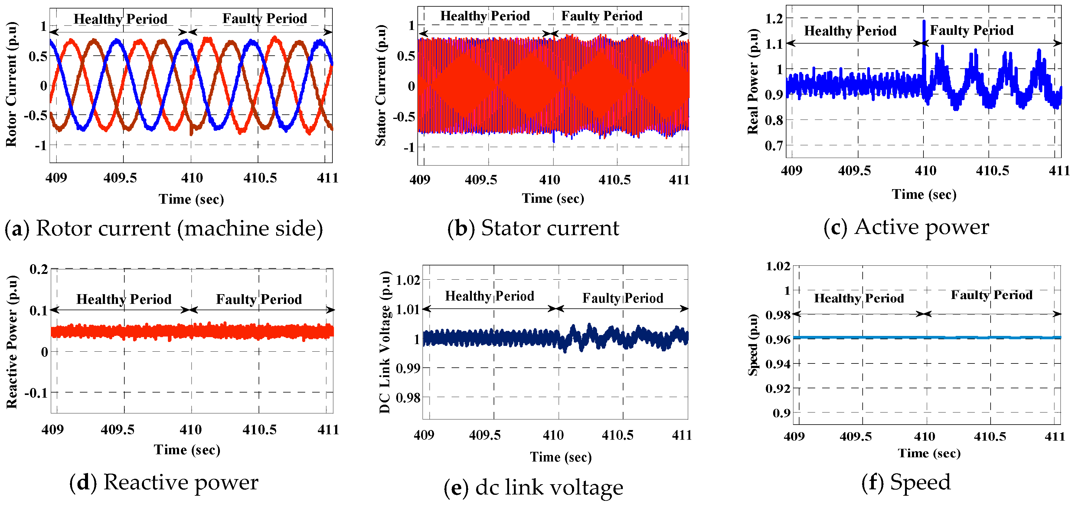
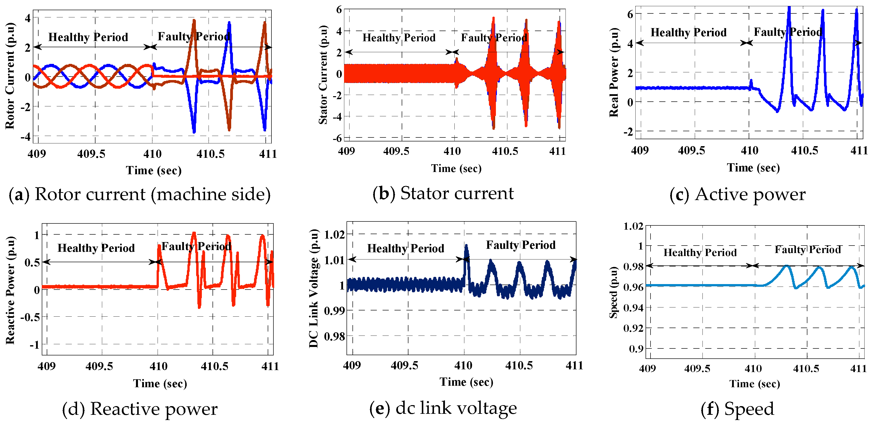
2.1. Converter Faults

A single-switch gate-drive open-circuit fault (upper switch) is injected into one of the parallel connected grid-side converter (GSC) at 160 s, and the results are shown in Figure 3. During the fault, the phase current corresponding to the faulty leg is distorted in upper half cycle, and the negative half cycle is found to be omitted, resulting in variation of phase and magnitude of the other two phase currents (Figure 3a); however, the current flowing through the other healthy converters are not affected as shown in Figure 3b. From the test results, it is inferred that: (i) the dc-link voltage fluctuates marginally in the faulty converter as shown in Figure 3c (oscillation at grid frequency), (ii) variation in both capacitor dc-link voltages as shown in Figure 3d, (iii) the power factor on grid side (rotor) fluctuates (Figure 3e) due to the variation in reactive power consumption, and (iv) the speed of the machine is constant as set by the machine-side control system. In the case of an open-circuit fault in lower switch, the results are similar to the upper switch; however, it is observed that (i) the phase current of the faulty leg is disturbed in lower half cycle, while it is omitted in upper half cycle, (ii) the variations in the dc-link capacitor voltages are reversed when compared to the open-circuit fault of the upper switch.

2.2. Sensor Faults

Single rotor current sensor omission fault is injected at 410 s, and the results are shown in Figure 4. During the fault, one of the current sensor reads zero value, resulting in changes in Iqr (q-axis (torque) component of machine). The changes in Iqr distort the electro-magnetic torque of the machine, resulting in fluctuations in the real power delivery and speed. From the results, it is observed that (i) the speed of the machine marginally fluctuates (Figure 4f), resulting in changes in the active power delivery (Figure 4c) and (ii) there are variations in rotor and stator currents (Figure 4a,b). Despite these variations, the machine is observed to be in continuous operation, and Idr maintains the controlled reactive power at grid (stator side). It is observed that all controllers are in regular operation in the grid-side converters, and the dc-link voltage is maintained.

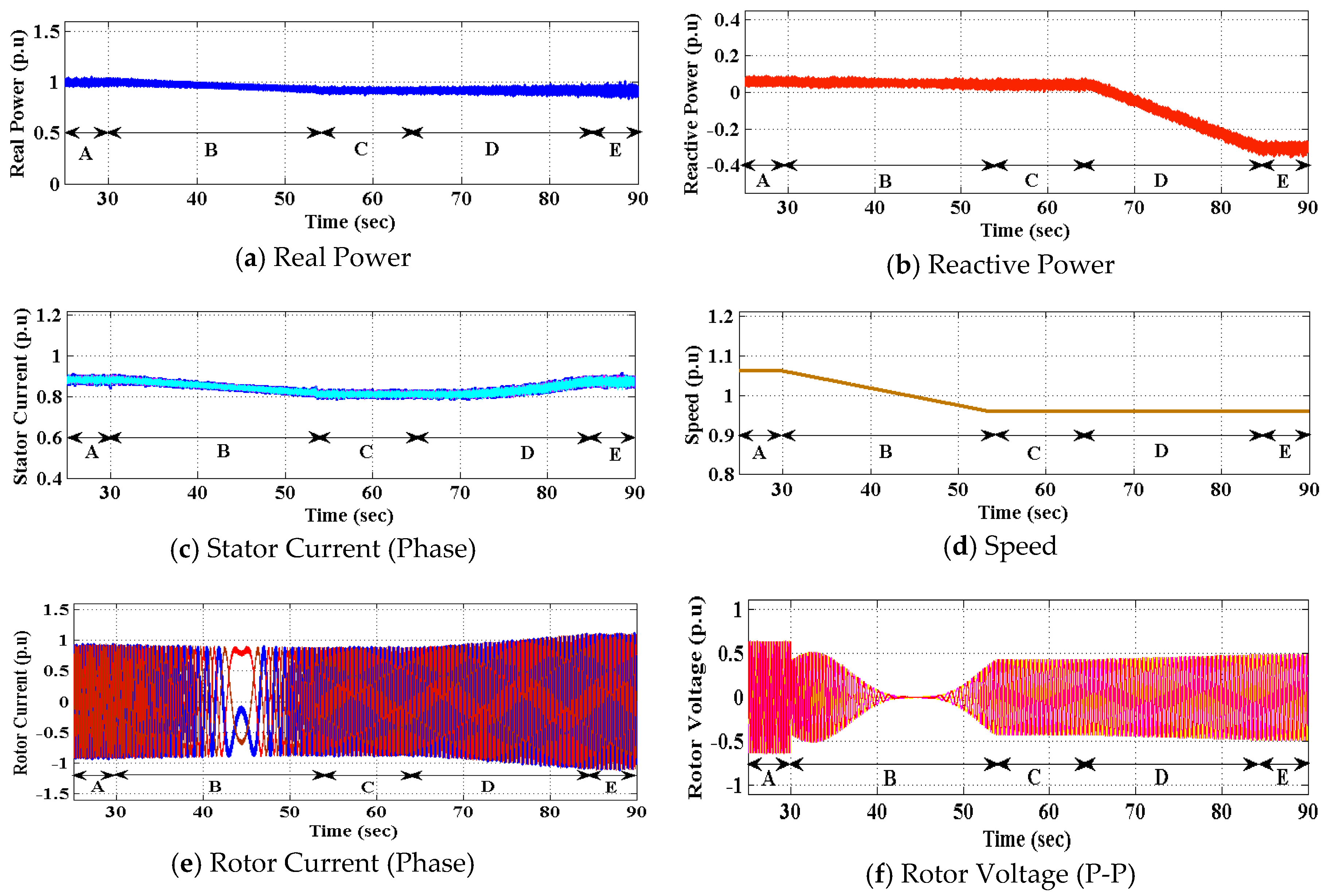
2.3. Rotor Winding Faults

Simulation study is repeated for single-phase rotor winding fault that is injected into machine side converter (MSC) at 410 s, and the results are shown in Figure 5. When a fault occurs, one of the rotor phase current goes to zero (Figure 5a), and the conduction mode is equivalent to the single-phase mode with other two healthy phases. During the fault, the magnitude of the rotor and stator phase transient currents increase to a level of 2.96 p.u. (Figure 5a) and 4.15 p.u. (Figure 5b), respectively. Consequently, the active and reactive powers of the machine are affected (Figure 5c,d). From the test results, it is observed that: (i) the healthy phase rotor currents undergo deviations in phase, and they produce transients at meeting point of these two phase currents, (ii) both stator and rotor currents increase to the levels above the rated value, (iii) there are fluctuations in dc-link voltage and speed of the machine, (iv) there is instability in active and reactive power delivery, and (v) the rotor side converter (both GSC and MSC) control system falls out of action. Likewise, all the power converter and sensor faults are injected, and the results are summarized in Table 1 and Table 2, respectively.

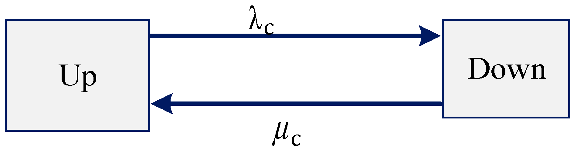
3. Markov Reliability Model

Reliability is a term used to measure the successful rate of operation of equipment/components in a given period. Let us assume that an equipment is in successful operation in the interval from time t1 to time t2. Then, ‘F’ is a variable denoting time to failure in an equipment, and reliability of the equipment is mathematically defined as,
R ( t ) = P ( F > t 2 ) t 2 0
P Probability .
Mean Time to Failure (MTTF) is given by,
MTTF = 0 R ( t ) dt
In general, a component failure is exponentially distributed in reliability analysis. Therefore, reliability is given by
R ( t ) = e λ t
λ Failure rate over the period, and it is reported as constant. t Time period between initial commissioning and the instant of susceptibility to fail.
Exponential distribution shows that the reliability decays to zero when the component ages. For a single component, MTTF is also given by,
MTTF = 1 λ
In a series system, with ‘n’ components having failure rates λ1, λ2, …, λn and reliability functions R1(t), R2(t), …, Rn(t), the overall reliability function and MTTF are given by,
R s ( t ) = i = 1 n R i ( t ) = e λ s t where , λ s = i = 1 λ i
MTTF = 1 i = 1 n λ i
Reliability for ‘n’ paralleled systems is given by,
R p ( t ) = 1 i = 1 n ( 1   R i ( t ) ) = 1 i = 1 n ( 1 e λ i t )
Availability of an equipment is considered by the time to repair and number of failures. System availability is mathematically given by,
A u = T up T up + T down
A u unit   Availability ; T up unit   uptime ; T down unit   downtime .

4. Reliability Calculation of a 250-MW DFIM Variable-Speed Unit

Reliability of a 250-MW DFIM unit is estimated with the following assumptions: (i) all the components/equipment are operational during their scheduled period, (ii) input power supply has been fully reliable. The reliability model is created by considering the working and failure conditions of each component used in the variable-speed unit. Two-state block models are developed to determine the reliability and availability of each component. Subsequently, the reliability of the entire unit is determined.

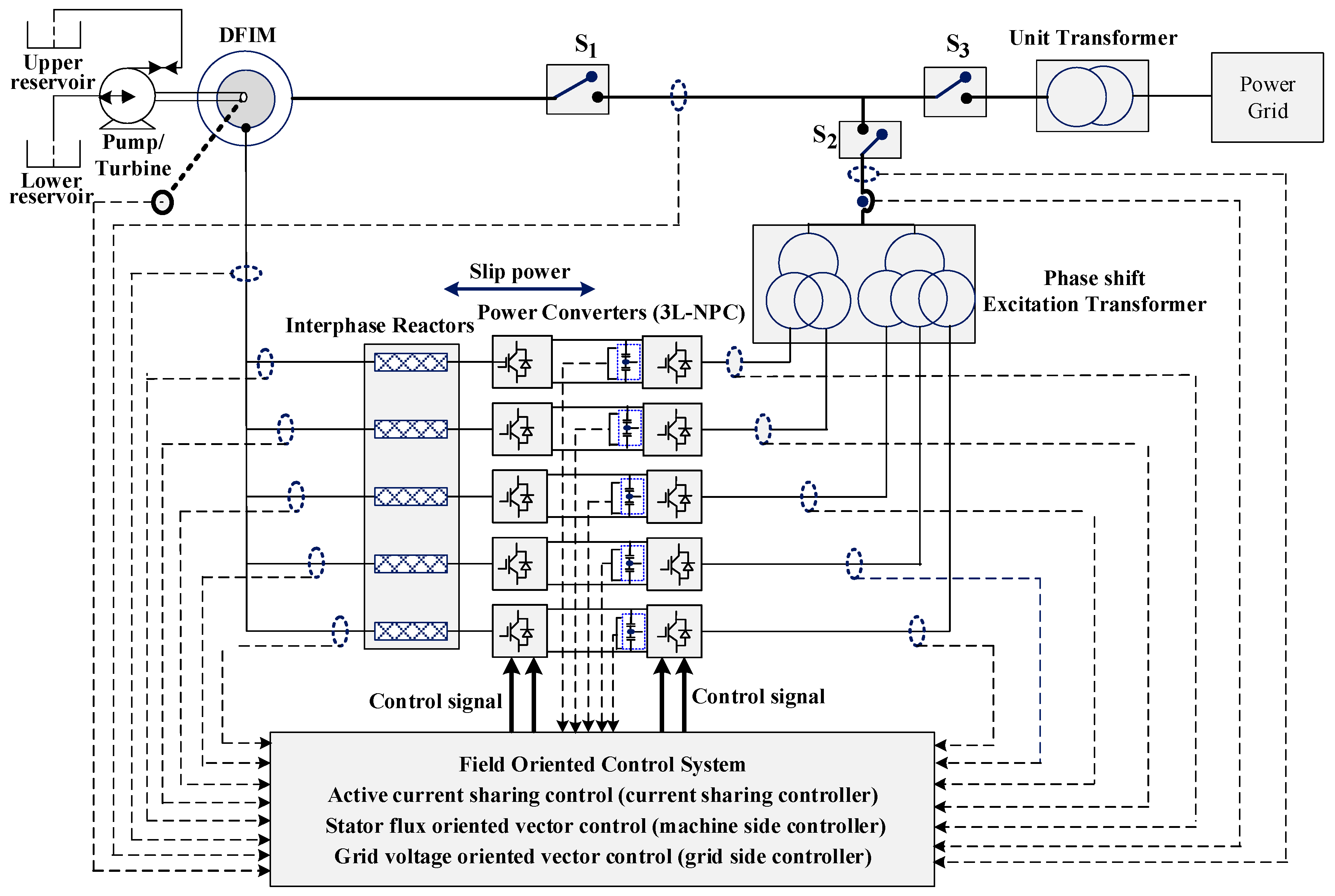
4.1. Power Converter Modelling

A five-channel three-level back-to-back voltage source converter is used in the variable-speed unit to control the active and reactive powers of the drive. Each converter is rated as 8 MVA (3.3 kV; 11,600 A) to handle the large rotor current. IEGT-based (injection enhanced gate transistor) switches are used in these converters in view of the low on-state voltage drop and efficiency improvement. Two capacitors are placed in the dc-link to resist the dc-link voltage of 5000 V (i.e., dc-link voltage is 2500 V each) and the dc-link capacitance value is selected as 18,000 µF in view of the ripples and the protection requirements during the grid disturbances [29]. In addition, a crowbar and a dc-link chopper circuit are placed in the converter circuit to protect the converter from the internal and external faults. It is reported that power converter redundancy is not yet adopted in the commissioned/under construction variable speed PSPP units due to operational issues; therefore, if a failure occurs in any one of the converters, then the entire unit trips. Hence, the converter would be considered as connected in series with other components. It follows a two-state model with the Up (healthy operation) and Down (failed operation) states (Figure 6). Block model helps determining precise failure rate ( λ c ) and repair rate ( μ c ) of the converter. The failure rate of each component used in the converter is shown in Table 3. Further, failure rates of each machine side and grid-side converter [31] is shown in Table 4. Failure rate is defined as number of failures occurs per operating hours (109 h). Average time to repair a converter is 14 h [32].

4.2. Sensor Modelling

Sensors are crucial components in controlling the drive. Being sensitive to the environment and operational conditions, they are prone to more kinds of fault such as (i) omission, (ii) gain, (iii) bias, (iv) constant/saturation, and (v) noise. A large number of sensors are used to control all the five converters. The sensors are considered as connected in series with other components, since it leads to shutdown of the entire unit even if a single sensor unit fails. However, DFIM drive is survived under some sensor failures including single rotor and grid current sensors as listed in Table 2. Therefore, estimation of reliability chain for the sensors is calculated based on Table 2. A Markov model for sensors is considered as the two-state model with the Up (healthy operation) and Down (failed operation) states. The average time taken to repair a sensor is 8 h. Failure rate of each sensor with respect to the fault is given in Table 5.

4.3. Converter Control System

Field-oriented vector control system is employed in the large-rated variable speed PSPP units to achieve accuracy and low ripple in torque. Stator flux-oriented vector control system is employed in the machine-side converters to control the active/reactive power of the DFIM, and grid voltage-oriented vector control system is employed to control the dc-link voltage of the back-to-back converter and maintain unity power factor at grid (rotor) through the grid-side converter. Active current sharing is also employed in the control system for proper sharing of rotor current. The average time taken to repair the control system is 14 h. Failure rate of each component of the control system is given in Table 6. As presented in Figure 6, the control system follows the two-state model with Up (healthy operation) and Down (failed operation) states. In addition, all components are connected in series considering the reliability aspect.

4.4. Transformer

The power transformer selected is a two-winding step-down transformer. The failure rate of power transformer is as high as 5940 FIT [32]. Power transformer (PT) unit has a primary and secondary windings, also each windings has three bushings. Major failures (i.e., 64%) occurs in windings (47.25%) and bushings (16.53%) [36]. Phase shift transformer (PST) is considered for the excitation system in a variable speed DFIM unit to limit the harmonics and circulating currents. It has two primary windings and five secondary windings with a phase shift of (Yd1 (−12°) d1 (−6°) d1 (0°) d1 (+6°) d1 (+12°)) as shown in Figure 1, each winding has three bushings. Each winding and bushing are considered as series in reliability chain of PST, since any failure in PST’s leads to affecting converter power output and leads to shut down the entire unit. Failure rate of PST’s is similar to the power transformer unit [37]. However, it has two primary and five secondary windings, the failure rate for PST is estimated as 20,790 FIT (i.e., (7/2) × 5940 = 20,790). The average time taken to repair the transformer is 26 h, although it takes 168 h for a major replacement. A two-state model is adopted, and the power and excitation transformers are connected in series with other components.

4.5. Doubly Fed Induction Machine

Failure rate of DFIM is estimated as 14,040 FIT [32]. The major failures are related to the slip rings (31.1%), bearings (11.6%), and rotor (7.4%). Average time to repair the machine is 24 h, although it takes 168 h for a major replacement, similar to the case of the transformer. The machine components are connected in series considering the reliability, and a two-state model is adopted.

4.6. Interphase Reactors

Interphase reactors (IR) are used for proper sharing of current among the converters and for limiting the circulating currents in the machine-side converters. The failure rate of IR is 950 FIT [35]. The estimated time for repair/replacement of IR is 21 h. The reactors are connected in series with other components and considered as two-state model.

4.7. Circuit Breakers

Two-state model (based on Markov model) is adopted for the circuit breakers that are connected in series with other components. Failure rate and time to repair are considered as 640 FIT [35] and 19 h, respectively.

4.8. Cooling System

The cooling system of the variable-speed unit consists of fans, water, air circulation systems, pumps, etc. Failure rate and time to repair are considered as 3200 FIT and 14 h, respectively. It is considered as a two-state Markov model.

4.9. Cabling

The incoming (grid-to-converter) and outgoing (converter-to-rotor winding) cables are considered as two-state models, and these are connected in series with other components. Average failure rate is considered as 800 FIT [35] and time taken for repair/replacement is 21 h. The failure rate depends on the length of the cable.

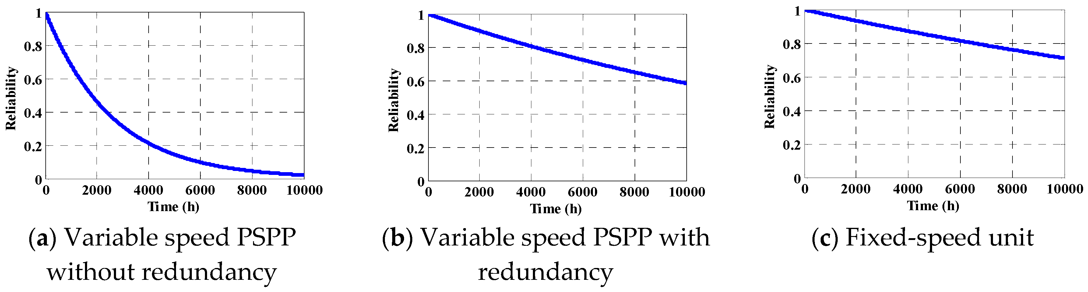
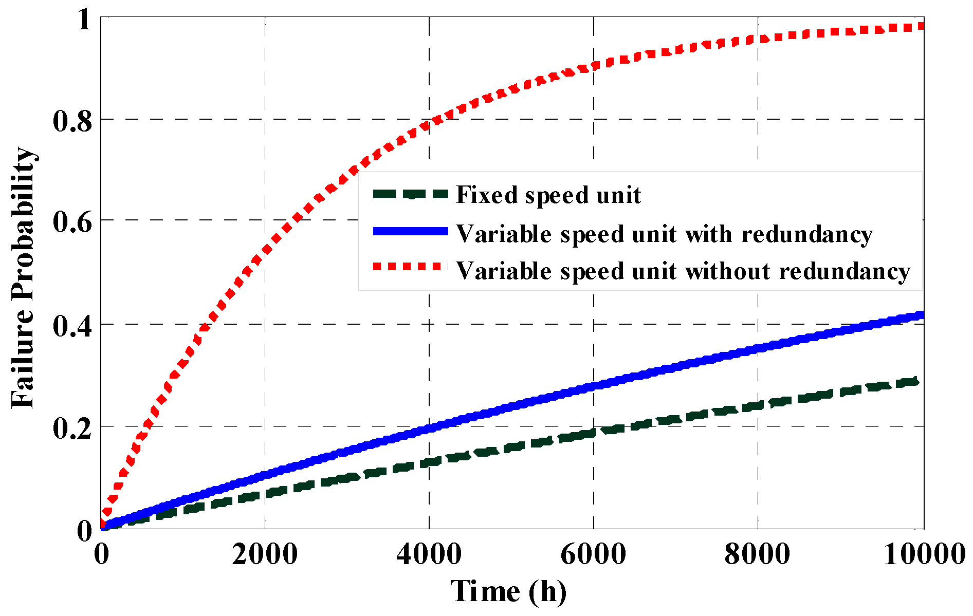
5. Reliability Estimation of a 250-MW DFIM Variable-Speed Unit

A reliability model (based on the Markov model) is developed for the equivalent block representing the overall unit, and the reliability and availability of the unit is calculated. Since all the components are represented individually using two-state model, the equivalent variable-speed unit model is represented as two-state model. Since all the components of the unit are connected in series, the failure rate for the overall unit is calculated based on (5). It is worth mentioning that the survivability of the unit is considered during the estimation of failure rate. In the case of current sensors, two sensors are used while the third is not of any significance. The system failure rate is given as,
λ s = λ converter + λ sensors + λ control   system + λ DFIM + λ Transformer + λ Interphase   reactors + λ Circuit   breakers + λ Cooling   Systems + λ Cabling
λ s = 387005   FIT
Based on the system failure rate, reliability of the whole unit is estimated as shown in Figure 7a. MTTF is calculated as
MTTF = 0 R s ( t ) dt = 0 e ( 3.39 t ) = 0.295   ( year )
It is observed from the figure that the system reliability under steady state condition (i.e., initial reliability state of the unit) is 0.9996. However, reliability is considered as an exponential function as shown in Figure 7a. The repair rate of the year is estimated as 197.53 repairs/year. It is observed that the availability of the variable speed PSPP unit is estimated as 0.9775.

5.1. Reliability Calculation with Power and Control Redundancy

In this section, it is assumed that the redundancy in both power converter and control circuit is applied to variable-speed unit. The reliability of the unit is calculated as shown in Figure 7b, and it is observed to be 0.999 at steady state condition. The repair rate of the year is estimated as 73.5 repair/year. It is observed that the availability of the variable speed PSPP unit is 0.9916 considering the redundancy in power converter and control circuit. The MTTF of the variable-speed unit with redundancy is calculated as,
MTTF = 0 R s ( t ) dt = 0 e ( 1.0696 t ) = 0.934   ( year )

5.2. Reliability Calculation for Fixed-Speed Unit

Synchronous machine employing fixed speed is considered for the calculation of reliability and availability of the unit. In a fixed-speed PSPP, thyristor-based converters are used in the excitation system. It is noted that the 2 + 1 redundancy in power converter and control circuit is adopted in fixed-speed unit. Failure rate for the synchronous machine with excitation system is 8300 FIT. Also, phase-shift transformers are not adopted in these power plants where single channel is enough to provide the required rotor current. Static frequency converters (SFC) are used in fixed-speed PSPPs during the starting-up process of pumping mode. The failure rate of SFC is similar to the back-to-back converter discussed in Section 4; nonetheless, the operating hours of SFC is bare minimum i.e., less than 300 h/year. The reliability of the unit is calculated, and it is shown in Figure 7c. It is observed that the reliability of the fixed-speed unit at steady state condition is 0.9998. The repair rate of the year is estimated as 30.7 repair/year. It is observed that the availability of the variable speed PSPP unit is 0.9964. MTTF of the fixed-speed unit is considered as,
MTTF = 0 R s ( t )   dt = 0 e ( 0.3789 t ) = 2.63   ( year )
The comparison of failure rate and availability between the fixed- and variable-speed units is shown in Table 7 and Table 8, respectively, and that of failure probability is shown in Figure 8. It is inferred that the availability of the PSPP unit is low in a variable-speed unit without redundancy of power converter and control circuit; however, providing redundancy helps enhance the availability to a level comparable with fixed speed unit.

6. Conclusions

This paper presents the reliability and availability of a large-rated (250-MW) DFIM-fed variable speed pumped-storage power plant using a Markov reliability model. The availability of the unit is calculated using the failure rate and time to repair the individual equipment of the unit. The result shows that the mean time-to-failure (MTTF) of the variable-speed unit is low compared to that of a fixed-speed unit, and the availability is observed to be 0.9775 per year for the variable-speed unit compared to 0.9964 per year for the fixed-speed unit. The estimated mean time to failure (MTTF) of as low as 0.295 years is considered to be a minimum value for a large pumped-storage plant. In addition, the availability of the variable-speed unit is marginally lower by 2% compared with that of the fixed-speed unit; however, with redundancy in power converter and control circuits, the availability improves considerably, and it is expected to provide confidence to the policy makers and project authorities of hydro power plants.

Author Contributions

K.-B.L. and T.R.C. provided guidance and supervision. S.S.L. conceived the idea of reliability portion of this paper and performed the Markov reliability model. A.J. implemented the main research, performed the literature review, simulation, collecting technical details, wrote and revised the manuscript as well. All authors have equally contributed to the simulation results, reliability calculation and result discussions.

Funding

This work was supported by the Korea Institute of Energy Technology Evaluation and Planning (KETEP) and the Ministry of Trade, Industry & Energy (MOTIE) of the Republic of Korea (No. 20171210201100) and “Human Resources Program in Energy Technology” of the Korea Institute of Energy Technology Evaluation and Planning (KETEP), granted financial resource from the Ministry of Trade, Industry & Energy, Republic of Korea. (No. 20174030201660).

Acknowledgments

Authors thank Power Electronics Laboratory of Electrical & Computer Engineering Department, Ajou University, South Korea for the research fellowship. Also contribution of Hydropower Simulation Laboratory of Indian Institute of Technology Roorkee, India is highly acknowledged.

Conflicts of Interest

The authors declare no conflict of interest.

References

  1. Pérez-Diaz, I.; Chazarra, M.; González, J.G.; Cavazzini, G.; Stoppato, A. Trends and challenges in the operation of pumped-storage hydropower plants. J. Renew. Sustain Energy Rev. 2015, 44, 767–784. [Google Scholar] [CrossRef]
  2. Cavazzini, G.; Pérez-Diaz, J.I. Technological Developments for Pumped Hydro Energy Storage; Technic Report; European Energy Research Alliance: Brussels, Belgium, 2014; pp. 1–128. [Google Scholar]
  3. Energy Storage Association. Variable Speed Pumped Hydroelectric Storage; Technic Report; Energy Storage Association: Washington, DC, USA, 2018. [Google Scholar]
  4. United States Department of Energy Global Energy Storage Database. Pumped Storage Plant; Technic Report; United States Department of Energy Global Energy Storage Database: Washington, DC, USA, February 2017. [Google Scholar]
  5. Toshiba Energy Systems & Solutions. Adjustable Speed Pumped Storage Plant—Advantages of Adjustable Speed and Quick Response; Technic Report; Toshiba Energy Systems & Solutions: Kanagawa, Japan, 2018; pp. 1–24. [Google Scholar]
  6. Lefebvre, N.; Tabarin, M.; Teller, O. A solution to intermittent renewables using pumped hydropower. Renew. Energy World Mag. May 2015, 3, 50–53. [Google Scholar]
  7. Schlunegger, H.; Oberhasli, A.T. 100 MW Full-Size Converter in the Grimsel 2 Pumped-Storage Plant; Technic Report; Oberhasli Hydroelectric Power Company: Innertkirchen, Switzerland, 2013. [Google Scholar]
  8. Lung, K.L.; Hung, Y.; Lu, W.; Kao, W.S. Modeling and dynamic simulations of doubly fed adjustable-speed pumped storage units. IEEE Trans. Energy Convers. 2007, 22, 250–258. [Google Scholar] [CrossRef]
  9. Kuwabara, T.S.; Furuta, A.; Kita, H.; Mitsuhashi, E. Design and dynamic response characteristics of 400MW adjustable speed pumped storage unit for Ohkawachi power station. IEEE Trans. Energy Convers. 1996, 11, 376–384. [Google Scholar] [CrossRef]
  10. Joseph, A.; Chelliah, T.R. A Review of Power Electronic Converters for Variable Speed Pumped Storage Plants: Configurations, Operational Challenges and Future Scopes. IEEE J. Emerg. Sel. Top. Power Electron. 2018, 6, 103–119. [Google Scholar] [CrossRef]
  11. An, C.; Lloyd, G.J.; Smith, B.; Zou, L.; Girardot, E.; Schwery, A.; Wechsler, A.; Perugini, G.; Kawkabani, B. Design and testing of a new protection relay for variable speed DFI motor generators. In Proceedings of the 12th IET International Conference Developments in Power System Protection, Copenhagen, Denmark, 31 March–3 April 2014; pp. 1–6. [Google Scholar]
  12. Dujic, D. Pumped Hydro Storage Power Plants Emulation Platform. Power Electronics Laboratory-News, 19 January 2018. [Google Scholar]
  13. Joseph, A.; Desingu, K.; Semwal, R.R.; Chelliah, T.R.; Khare, D. Dynamic performance of pumping mode of 250 MW variable speed hydro-generating unit subjected to power and control circuit faults. IEEE Trans. Energy Convers. 2018, 33, 430–441. [Google Scholar] [CrossRef]
  14. Central Electricity Authority of India. Technical Standards for Connectivity to the Grid—Hydropower Plant; Technic Report; Central Electricity Authority of India: New Delhi, India, 2007. [Google Scholar]
  15. Jou, S.-T.; Lee, S.-B.; Park, Y.B.; Lee, K.-B. Direct power control of a DFIG in wind turbines to improve dynamic responses. J. Power Electron. 2009, 9, 781–790. [Google Scholar]
  16. Chwa, D.; Lee, K.-B. Variable structure control of the active and reactive powers for a DFIG in wind turbines. IEEE Trans. Ind. Appl. 2010, 46, 2545–2555. [Google Scholar] [CrossRef]
  17. Giaourakis, D.G.; Safacas, A.N. Effect of short-circuit faults in the back-to-back power electronic converter and rotor terminals on the operational behavior of the doubly-fed induction generator wind energy conversion system. J. Mach. 2015, 5, 2–26. [Google Scholar] [CrossRef]
  18. Saleh, S.A.; Aljankawey, A.S.; Abu-Khaizaran, M.S.; Alsayid, B. Influences of power electronic converters on voltage–current behaviors during faults in DGUs—Part I: Wind energy conversion systems. IEEE Trans. Ind. Appl. 2015, 51, 2819–2831. [Google Scholar] [CrossRef]
  19. Lee, J.S.; Lee, K.B.; Blaabjerg, F. Open-switch fault detection method of a back-to-back converter using NPC topology for wind turbine systems. IEEE Trans. Ind. Appl. 2015, 51, 325–335. [Google Scholar] [CrossRef]
  20. Shevchuk, V.P. Investigations of the operation reliability increase of the alternating current electric machines in diamond extractive industries. In Proceedings of the 8th International Scientific and Practical Conference of Students, Post-graduates and Young Scientists Modern Technique and Technologies, Tomsk, Russia, 12 April 2002; pp. 103–104. [Google Scholar]
  21. Lopez, J.; Sanchis, P.; Roboam, X.; Marroyo, L. Dynamic behavior of the doubly fed induction generator during three-phase voltage dips. IEEE Trans. Energy Convers. 2007, 22, 709–717. [Google Scholar] [CrossRef]
  22. Hu, S.; Lin, X.; Kang, Y.; Zou, X. An improved low-voltage ride-through control strategy of doubly fed induction generator during grid faults. IEEE Trans. Power Electron. 2011, 26, 3653–3665. [Google Scholar] [CrossRef]
  23. Lee, S.B.; Lee, K.-B.; Lee, D.-C.; Kim, J.M. An improved control method for a DFIG in a wind turbine under an unbalanced grid voltage condition. J. Electr. Eng. Technol. 2010, 5, 614–622. [Google Scholar] [CrossRef]
  24. Oliver, J.A.; Poteet, D. High-speed, high-horsepower electric motors for pipeline compressors: Available ASD technology, reliability, harmonic control. IEEE Trans. Energy Convers. 1995, 3, 470–476. [Google Scholar] [CrossRef]
  25. Bozzo, R.; Fazio, V.; Savio, S. Power electronics reliability and stochastic performances of innovative ac traction drives: A comparative analysis. In Proceedings of the 2003 IEEE Bologna Power Tech Conference Proceedings, Bologna, Italy, 23–26 June 2003; pp. 1–7. [Google Scholar]
  26. Klug, R.D.; Griggs, M. Reliability and availability of megawatt drive concepts. In Proceedings of the 2004 International Conference on Power System Technology, Singapore, 21–24 November 2004; pp. 665–671. [Google Scholar]
  27. Wikstrom, P.; Terens, L.A.; Kobi, H. Reliability, availability, and maintainability of high-power variable-speed drive systems. IEEE Trans. Ind. Appl. 2000, 36, 231–241. [Google Scholar] [CrossRef]
  28. Rausand, M.; Høyland, A. System Reliability Theory: Models, Statistical Methods, and Applications, 2nd ed.; Wiley: Hoboken, NJ, USA, 2005. [Google Scholar]
  29. Joseph, A.; Selvaraj, R.; Chelliah, T.R.; Sarma, A. Starting and Braking of a Large Variable Speed Hydro- Generating Unit Subjected to Converter and Sensor Faults. IEEE Trans. Ind. Appl. 2018, 54, 3372–3382. [Google Scholar] [CrossRef]
  30. Friedli, T.; Kolar, J.; Rodriguez, J.; Patrick, W. Comparative evaluation of three-phase AC-AC matrix converter and voltage dc-link back-to-back converter systems. IEEE Trans. Ind. Electron. 2012, 59, 4487–4510. [Google Scholar] [CrossRef]
  31. Xie, K.; Jiang, Z.; Li, W. Effect of wind speed on wind turbine power converter reliability. IEEE Trans. Energy Convers. 2012, 27, 96–104. [Google Scholar] [CrossRef]
  32. Carroll, J.; McDonald, A.; McMillan, D. Failure rate, repair time and unscheduled O&M cost analysis of offshore wind turbines. Wind Energy 2016, 19, 1107–1119. [Google Scholar]
  33. Al Mamun, M.; Yoshizawa, D.; Mukunoki, M. Performance evaluation of a large capacity 3-level IEGT inverter. In Proceedings of the 2013 IEEE ECCE Asia Downunder, Melbourne, VIC, Australia, 3–6 June 2013; pp. 201–207. [Google Scholar]
  34. Bazzi, A.M.; Dominguez-Garcia, A.; Krein, P.T. Markov reliability modeling for induction motor drives under field-oriented control. IEEE Trans. Power Electron. 2012, 27, 534–546. [Google Scholar] [CrossRef]
  35. Molaei, M.; Oraee, H.; Fotuhi-Firuzabad, M. Markov model of drive motor systems for reliability calculation. In Proceedings of the 2006 IEEE International Symposium on Industrial Electronics, Montreal, QC, Canada, 9–13 July 2006; pp. 2286–2291. [Google Scholar]
  36. Sodha, N.S. Power Transformers Failure Modes, Investigation & Prevention Techniques; Technic Report; Power Grid: Gurgaon, India, 2016. [Google Scholar]
  37. Siemens. Phase Shifting Transformer—Quality and Reliability; Technic Report; Siemens: Munich, Germany, 2018; pp. 1–10. [Google Scholar]
Figure 1. Large-rated DFIM-based variable speed PSPP unit.
Electronics 07 00265 g001
Figure 2. Active and reactive power control of 250 MW DFIM. A—260 MW, 15.3 MVAr (consumption), 245 rpm; B—Transition from 260 to 240 MW, 245 to 221.5 rpm, 15.3. MVAr (consumption); C—240 MW, 221.5 rpm, 15.3 MVAr (consumption); D—Transition from 15.3 MVAr (consumption) to 91.8 MVAr (Deliver to grid); E—240 MW, 91.8 MVAr (Deliver to grid), 221.5 rpm.
Electronics 07 00265 g002
Figure 3. GSC upper single-switch open-circuit faults for a 250-MW DFIM unit.
Electronics 07 00265 g003
Figure 4. Single rotor current sensor omission fault for a 250-MW DFIM unit.
Electronics 07 00265 g004
Figure 5. Single-phase rotor winding fault for a 250-MW DFIM unit.
Electronics 07 00265 g005
Figure 6. Two-state model for power converter.
Electronics 07 00265 g006
Figure 7. Reliability of a 250-MW pumped-storage power plant unit.
Electronics 07 00265 g007
Figure 8. Failure probability of a 250-MW pumped-storage power unit.
Electronics 07 00265 g008
Table 1. Survivability status for power converter faults [13,30].
SystemFaultsFault Status
Power ConverterMachine side converterSingle Device/Leg Open Circuit FaultF
Single Device/Leg Short Circuit FaultF
Grid side converterSingle Device/Leg Open Circuit FaultS
Single Device/Leg Short Circuit FaultF
DC LinkOpen circuit/Short circuitF
S—Survived; F—Failed.
Table 2. Survivability status for sensor faults [13].
SystemFaultsFault Status
SensorsOmission/saturationSpeed sensorF
DC link voltage sensorF
Reactive power signalF
Single rotor Current SensorS
Single grid current sensorS
Single grid voltage sensorF
Gain/BiasSpeed sensorF
DC link voltage sensorF
Reactive power signalS
Single rotor Current SensorS
Single grid current sensorF
Single grid voltage sensorS
S—Survived; F—Failed.
Table 3. Failure rate for power converter components [31,33].
S.NoComponentsFailure Rate (1 FIT = 1 Failure over 109 h)
1Power IEGT100 FIT
2Power Diode80 FIT
3DC-Link Capacitance300 FIT
4DC-Link45 FIT
Table 4. Failure rate for power converter [31].
S.NoComponentsFailure Rate (1 FIT = 1 Failure over 109 h)
1Grid Side Converter5562 FIT
2Machine Side Converter46,040 FIT
Table 5. Failure rate for sensors [32,34].
S.NoSensorType of FaultFailure Rate (1 FIT = 1 Failure over 109 h)
1Speed encoderOmission740
Gain190
Bias420
Constant190
Noise190
2Current sensorOmission/Gain/Bias/Constant/Noise100
3Voltage sensorOmission/Gain/Bias/Constant/Noise160
Table 6. Failure rate for control system components [35].
S.NoComponentsFailure Rate (1 FIT = 1 Failure over 109 h)
1Control power supply800 FIT
2Binary I/O800 FIT
3Main processing board800 FIT
4Pulse processing board400 FIT
5Communication board200 FIT
6Operator panel400 FIT
7Internal I/O board400 FIT
8External I/O board800 FIT
Table 7. Failure rate and reliability chain of pumped-storage power plants.
S.NoComponentsFixed Speed PSPP
(Single Channel Power Converter ****)
Variable Speed PSPP
(Five Channel Power Converter ****)
Without RedundancyWith Redundancy
Failure RateReliability ChainFailure RateReliability ChainFailure RateReliability Chain
1Power Converters4267Parallel *277,135Series36,950Parallel ***
2Converter Control System3200Parallel *27,600Series3680Parallel ***
3Sensors1620Parallel27,630Series/parallel **27,630Series/Parallel **
4Machine8300Series14,040Series14,040Series
5Power Transformer5940Series5940Series5940Series
6Excitation Transformer5940Series20,790Series20,790Series
7Interphase Reactors/Filters950Series4750Series4750Series
8Circuit Breakers1920Series1920Series1920Series
9Cooling System3200Series3200Series3200Series
10Cabling800Series4000Series4000Series
**** excitation system. * 2 + 1 redundancy in power converter and control circuit is adopted. ** based on Table 2. *** Assumed standby (redundancy) power converter and control circuit are implemented.
Table 8. Availability of pumped-storage power plants.
S.NoParticularsPumped-Storage Power Plant Unit (250 MW)
Variable-Speed UnitFixed-Speed Unit
Without RedundancyWith Redundancy
1MTTF (years)0.2950.9342.63
2Availability0.97750.99160.9964

