Abstract
Designing chaotic oscillators using complementary metal-oxide-semiconductor (CMOS) integrated circuit technology for generating multi-scroll attractors has been a challenge. That way, we introduce a current-mode piecewise-linear (PWL) function based on CMOS cells that allow programmable generation of 2–7-scroll chaotic attractors. The mathematical model of the chaotic oscillator designed herein has four coefficients and a PWL function, which can be varied to provide a high value of the maximum Lyapunov exponent. The coefficients are implemented electronically by designing operational transconductance amplifiers that allow programmability of their transconductances. Design simulations of the chaotic oscillator are provided for the m CMOS technology. Post-layout and process–voltage–temperature (PVT) variation simulations demonstrate robustness of the multi-scroll chaotic attractors. Finally, we highlight the synchronization of two seven-scroll attractors in a master–slave topology by generalized Hamiltonian forms and observer approach. Simulation results show that the synchronized CMOS chaotic oscillators are robust to PVT variations and are suitable for chaotic secure communication applications.
1. Introduction
Chaotic systems have been studied for a long time and nowadays many examples of electronic implementations using discrete devices can be found in the literature. However, the big challenge remains the generation of multi-scroll attractors and their design using CMOS integrated circuit (IC) technology to develop real life applications. For instance, the control and synchronization of chaotic systems were first proposed no more than three decades ago [,,,,,,], from which some practical developments have impacted areas such as high-performance circuit design (e.g., delta-sigma modulators and power converters), liquid mixing, chemical reactions, biological systems (e.g., sensing signals produced in the human brain, heart or other organs), power electronics, secure communication systems, etc. [,,,,,]. That way, this new and challenging line for research and development is becoming highly inter-disciplinary, involving systems and control engineers, theoretical and experimental physicist, applied mathematicians, physiologists and, above all, IC design specialists.
Relevant electronic implementations of chaotic oscillators are summarized in [], where one can see the usefulness of piecewise-linear (PWL) functions to generate attractors as for the well-known double-scroll Chua’s circuit [,,,]. If the PWL function modeling the Chua’s diode is augmented to have more break-points, by combining slopes, one can generate multi-scroll chaotic attractors [,]. In addition, adding more PWL functions allows generating multi-scroll attractors not only in one direction (1D) [,], but also in two (2D) [], three (3D) [], and four directions (4D) [].
From the electronic design point of view, the majority of chaotic oscillators are based on the traditional voltage operational amplifier []. However, there are many drawbacks related to this approach, such as requiring a high number of amplifiers and passive elements for its design, they have low frequency response, and require high voltage biases up to ±18 V. On the other hand, as already shown in [,], the good option to design CMOS chaotic oscillators is by using operational transconductance amplifiers (OTAs), which are biased using low voltages of around ±1.65 V or lower, and they provide higher frequency response than voltage amplifiers. However, the challenge in IC design is the generation of multi-scroll attractors, for which up to now the highest number of scrolls that have been generated is five [,]. In this manner, we introduce a CMOS design of a seven-scroll attractor that is based on a new current-mode PWL function that can be programmed to generate 2–7-scroll attractors. We performed post-layout simulations using m CMOS technology from AMS to guarantee robustness to process–voltage–temperature (PVT) variations. We also show the synchronization of two seven-scroll attractors to highlight that the proposed CMOS design can be suitable to develop applications in security and Internet of Things (IoT).
The rest of this article shows the CMOS design of a chaotic oscillator using OTAs and a new programmable current-mode PWL function to generate up to seven scrolls. The chaotic oscillator has four coefficients that have been optimized in [,,,] to provide a high maximum Lyapunov exponent (MLE). Section 2 lists feasible solutions providing different values of MLE. It is worth mentioning that the seminal work in [] introduced the first algorithm to compute Lyapunov exponents from experimental chaotic time series. Afterwards, other authors introduced different approaches to compute MLE [,,,,]. Section 3 details the design of the OTA that allows programmability of the transconductance, and introduces our proposed current-mode PWL function. The whole CMOS chaotic oscillator is introduced in Section 4, where we detail the programmability of the current-mode PWL function. Section 5 shows the master–slave synchronization of two CMOS chaotic oscillators. The layout of the chaotic oscillator has been performed using m CMOS technology, as shown in Section 6, where we highlight post-layout simulations including PVT variations for the synchronization of two seven-scroll chaotic attractors using generalized Hamiltonian forms and observer approach. Finally, the conclusions are listed in Section 7.
2. OTA-Based Chaotic Oscillator Using a CMOS Programmable Current-Mode PWL Function
Chaotic oscillators have a complex dynamical behavior that is associated to their high sensitivity to small variations in the initial conditions. They also have bounded trajectories in the phase space. They possess at least one MLE and have a continuous power spectrum [,,,,,,,]. Chaotic oscillators can be described by the state-space approach given by
where the dot denotes differentiation with respect to time and the functions and are in general nonlinear. In Equation (1), the variety of possible nonlinear functions is infinite, but, in some cases, they can be approached by PWL functions leading to the state-space representation given by
where and are matrices (possibly time-dependent) of appropriate dimensions. If the input vector is fixed or equals zero, the model describes an autonomous dynamical system.
Lets us consider the multi-scroll chaotic oscillator modeled by []:
where , and are real and positive constants, and models a saturated nonlinear function (SNLF) series that can be approached by a PWL function, as already shown in [,,,]. In Equation (3), the coefficients , and must have appropriate values to estimate the quality of chaotic behavior [,]. For example, one can evaluate Lyapunov exponents, Kaplan–York dimension and entropy. In this work. we focus on evaluating Lyapunov exponents, which are asymptotic measures characterizing the average rate of growth (or shrinkage) of small perturbations to the solutions of a dynamical system [], and provide quantitative measures of sensitivity of the system response to small changes in initial conditions [].
The Lyapunov exponents can be computed by applying numerical methods [,,]. Furthermore, the optimization of Equation (3) requires varying the coefficients to obtain high values of MLE, as already demonstrated in []. For instance, in [], three meta-heuristics (genetic algorithms (GA), differential evolution (DE), and particle swarm optimization (PSO)) have been applied to optimize MLE. When the coefficient values are fixed to 0.7, as already done in [,], the MLE value is 0.105422 to generate two-scroll, 0.138087 to generate three scrolls, 0.142087 to four scrolls, 0.134534 to five scrolls, 0.147785 to six scrolls, and 0.148159 to generate seven scrolls. However, after applying GA, DE and PSO, the optimized MLE values increase according to Table 1, where we list the mean value, standard deviation and coefficient values to generate two to seven scrolls.

Table 1.
Optimized MLE values to generate 2–7-scroll attractors applying GA, DE and PSO [].
The goal of this article is the introduction of a current-mode PWL function to design the chaotic oscillator in Equation (3), using CMOS technology to program the generation of 2–7-scroll attractors. That way, Table 1 is the reference to design the CMOS OTAs to accomplish the values of the coefficients , and . According to Trejo-Guerra et al. [], there are very few integrated designs presented in the literature with this purpose, and they only generate up to five-scroll attractors. In this article, we highlight the design of a CMOS programmable current-mode PWL function to generate up to seven-scroll. The main idea is sketched in Figure 1, where the PWL function is generated from an input voltage () to provides an output current . This PWL function can be generated in either voltage-mode or current-mode . This article details the CMOS design of the current-mode PWL function labeled as saturated nonlinear function (SNLF) in Figure 2, which shows the OTA-capacitor () implementation of Equation (3), where the state variables are , and . By applying Kirchhoff’s current law to Figure 2, one gets Equation (4), where SNLF is described by , and the equations resemble the original ones defined by Equation (3). The operating frequency is evaluated by .
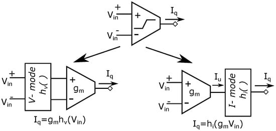
Figure 1.
Voltage-to-current implementations of the PWL function in: voltage-mode ; and current-mode .
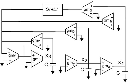
Figure 2.
OTA-based implementation of Equation (3), where SNLF represents the PWL function in current mode .
3. CMOS Design of the OTA Enabling the Proposed Current-Mode PWL Function
Figure 3 shows the CMOS topology of the OTA that is designed herein and allows programmability of its transconductance . Its CMOS design combines a differential pair with source degeneration to linearize , which is tuned by the feedback resistors R that are designed as active loads using MOSFETs controlled by voltage , as shown in Figure 4.
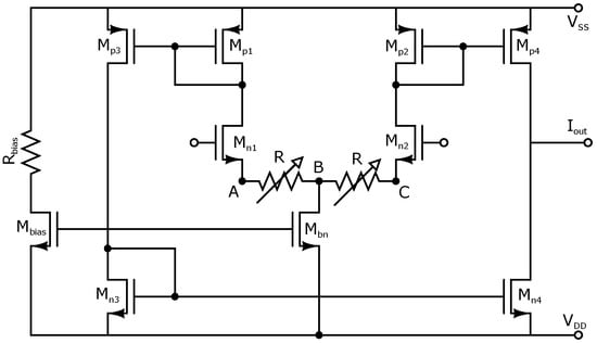
Figure 3.
CMOS OTA that allows programmability of .
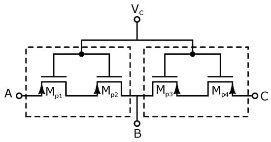
Figure 4.
CMOS design of resistors R in Figure 3, allowing programmability of through .
Looking at Table 1, the values of the optimized coefficients and are in the range , and coefficient c in the range . Therefore, to implement all those combinations of coefficients, the OTA for the former case is designed herein with a central transconductance of A/V, and with a tunable range of A/V. Considering the ranges of coefficient c, the OTA is designed with a central transconductance of A/V, and with a tunable range of A/V. Another OTA is designed to accomplish the slope required by the PWL function, with a central transconductance of mA/V, and with a tunable range of A/V. According to Equation (4), to implement the coefficients to generate seven scrolls (see Table 1, where [] = [0.93,0.52,0.21,0.96]), we select A/V, A/V, A/V, A/V and mA/V.
The sizes of the OTA having a central value of A/V are listed in Table 2. Table 3 lists its electrical characteristics. The is tuned by the feedback resistors R controlled by in the range [−5 V, −3 V]. The sizes of the MOSFETs for the active loads R are: –, m, m, and the multiplication factor .
Table 2.
Sizes of the OTA with different multiplicity (M) for the centered at A/V, A/V and 2 mA/V.
Table 3.
Performance ranges of the programmable OTAs with centered at A/V, A/V and 2 mA/V.
The sizes for the OTA designed with a central transconductance of A/V, are also listed in Table 2, and Table 3 lists its performance characteristics. These OTAs with centered transconductances at A/V and A/V are used to tune the coefficient values , and listed in Table 1. The integrators and PWL function also require OTAs with transconductance centered at mA/V. In this case, the transistor sizes are listed in Table 2, and Table 3 lists its performance characteristics.
PWL techniques have been used extensively in circuits and systems theory to model nonlinear characteristics of electronic devices [,], and to study a large class of nonlinear resistive networks [,]. A SNLF series can be generated using the CMOS topology shown in Figure 5 to generate the PWL function that allows programmability of the break-points by tuning the currents Ioff, Ioff and I to implement the required plateaus and slopes. This approach has the following advantages: (1) the current mode circuits are in open loop configuration, being unconditionally stable; (2) the current mode blocks have high frequency performance; (3) the simplicity and modularity of the current-mode blocks make them very appropriate to approach a PWL function; (4) a small number of transistors is required for each block; and (5) the current mode blocks allow programmability of the breakpoints for each segment of the PWL function. It should be noted that, to generate a slope , it is necessary to inject an input signal . All transistors have sizes L = 0.7 m and W = 3.5 m, but the multiplicity is 4 for and 12 for .
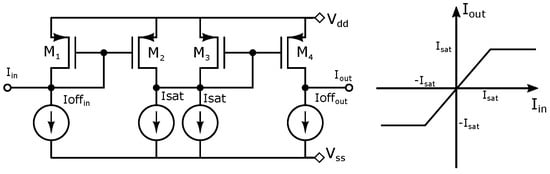
Figure 5.
CMOS design of the PWL function by cascading simple current mirrors.
4. Integrated Multi-Scroll Chaotic Oscillator Using the Proposed Current Mode PWL Function
The majority of CMOS chaotic oscillators are based on OTAs. For example, the authors in [] highlighted the benefits of low-voltage implementation, integrability and electronic tunability. Following this direction, in this work, we highlight the programmability of the PWL function enabled through current mode cells and the transconductances of the OTAs to tune the fractional values of the coefficients and listed in Table 1. By using the current mode cell shown in Figure 5, we propose the CMOS design sketched in Figure 6 to generate 2–7 scrolls by programming the parallel connection of all the saturated blocks. The current mode blocks are modified by the shift currents Ioff and Ioff. The saturated regions are limited by the bias current . That way, to connect current mode blocks to generate n-scroll, a 3–8-bit decoder is designed. As one sees, the input currents to each current mode block are copies of the input current , generated from the class AB current mirror shown in Figure 7. To generate seven scrolls, six copies of the input current are required. The transistor sizes of the multi-output current mirror using 0.35 m CMOS process from AMS are listed in Table 4. The electrical characteristics are: current gain of 1.005, dynamic range of mA, = 1.168 K, = 748.4 K, and A.
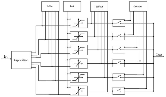
Figure 6.
Proposed programmable CMOS current mode PWL function to generate from two to seven scrolls.
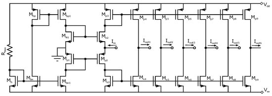
Figure 7.
Replication of the input current .
Table 4.
Sizes of the current mirror shown in Figure 7.
PVT variation simulations are performed to verify the robustness of our proposed current mode block using the BSIM3v3 model. The tested corners are: (NMOS–PMOS) typical–typical, fast–fast, fast–slow, slow–fast, and slow–slow (TT, FF, FS, SF, and SS, respectively) of the 0.35m CMOS technology. The temperature is swept from C to C in steps of C. Figure 8 and Figure 9 show the PVT simulation results.
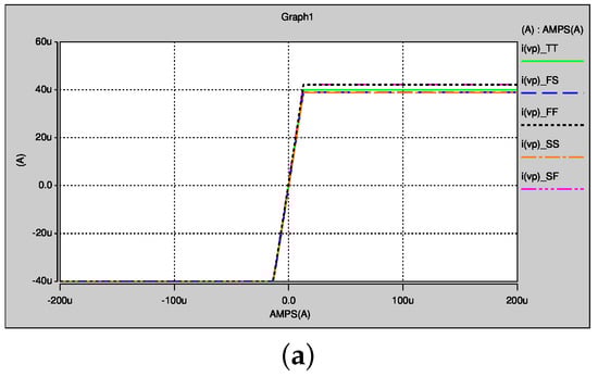
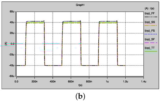
Figure 8.
PVT variations for Figure 6 at 5 MHz: (a) DC; and (b) time domain.
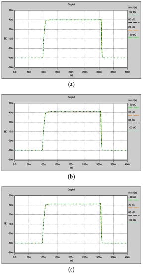
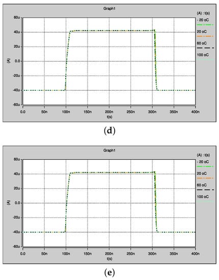
Figure 9.
Temperature variations of Figure 6 for the cases: (a) TT; (b) SF; (c) FS; (d) SS; and (e) FF.
Figure 10 shows the proposed circuit used to tune shown in Figure 6. Its sizes are listed in Table 5. Figure 11 shows the proposed circuit to tune and , and the transistor sizes are listed in Table 6. Table 7 shows the digital control word and the activation outputs of the 3-to-7-bit digital decoder, which is designed to select the number of current mode building blocks in Figure 6 for the generation of 2–7 scrolls. The output functions are shown in Figure 12, where , , , , , and .
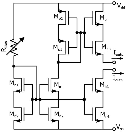
Figure 10.
Proposed circuit to tune in Figure 6.
Table 5.
Sizes of the circuit in Figure 10.
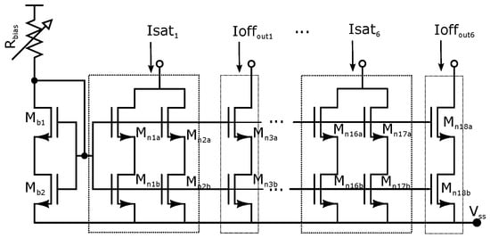
Figure 11.
Proposed circuit to tune and in Figure 6.
Table 6.
Sizes of the circuit in Figure 11.
Table 7.
Decoder 3-to-7-bit control.
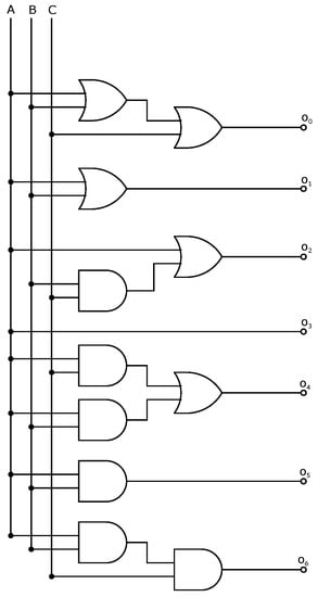
Figure 12.
Logic gates to implement the decoder.
A PWL function to generate two scrolls is implemented by setting the decoder inputs to logic , i.e., and . The shift currents are set to A, and A. A PWL function to generate three scrolls is implemented by setting , A, and A. A PWL function to generate four scrolls is implemented by setting , A, A, and A. A PWL function to generate five scrolls is implemented by setting , A, A, and A. A PWL function to generate six scrolls is implemented by setting , A, A, A, and A. Finally, a PWL to generate seven scrolls is implemented by setting , A, A, A, and A. For this last case, we show the simulation results in Figure 13, Figure 14 and Figure 15, respectively, to conclude that, with adjustment of the current shifts, our proposed current mode PWL function is robust to PVT variations and allows for programmability to choose any value between two- and seven-scroll attractors.
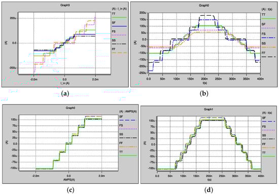
Figure 13.
PVT simulation of the proposed PWL function to generate seven-scroll: (a,b) without adjustment of the current offsets; and (c,d) with adjustment of the current offsets.
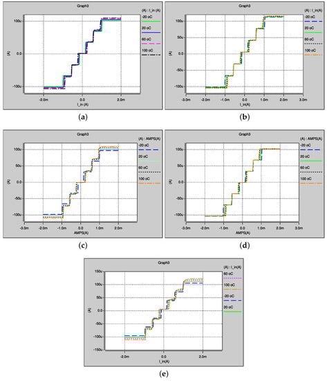
Figure 14.
Temperature variations of the proposed PWL function in DC to generate seven-scroll: (a) TT; (b) SF; (c) FS; (d) SS; and (e) FF corner.
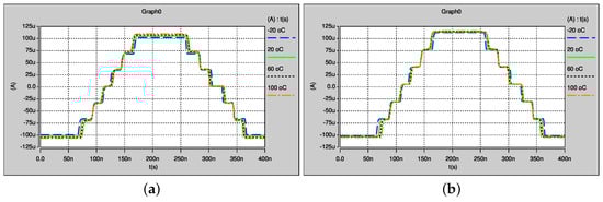
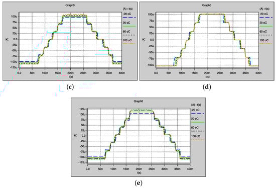
Figure 15.
Temperature variations of the proposed PWL function in time simulation to generate seven-scroll: (a) TT; (b) SF; (c) FS; (d) SS; and (e) FF corner.
5. Master–Slave Synchronization of Two Chaotic Oscillators
Chaos synchronization is an important problem in nonlinear science. During the last three decades, synchronization has received a great interest among various scientists [,,,,,,]. The synchronization can be seen as the property shared by some objects to express a uniform rate of coexistence. For example, two harmonic oscillators can be synchronized if their periods are equal. However, for the case of chaotic oscillators, the concepts of frequency and phase are not well defined and, therefore, two chaotic oscillators can be synchronized if eventually, after a transitional time (a long or short time span), the oscillations coincide exactly at all times despite both oscillators started at different initial conditions.
The idea of synchronizing two identical chaotic systems from different initial conditions was introduced in the seminal work in []. After that, several synchronization schemes were introduced in [,,,,,,,,,]. Besides, the practical applications of chaotic synchronization has some limitations to accomplish identical synchronization. For example, parameter mismatch will probably destroy the manifold of a synchronization. To deal with this issue, generalized synchronization approaches were introduced [,]. In this manner, we perform the synchronization of two chaotic oscillators following the approach given in []. Therefore, the chaos generator model from Equation (3) in Generalized Hamiltonian form, is given by
The Hamiltonian energy function can be described by
and the gradient vector can be described by
The destabilizing vector field calls for and signals to be used as the outputs of the master model (Equation (5)). The matrices , and I are given by
The pair () is observable. Therefore, the nonlinear state observer for Equation (5) to be used as the slave model is designed as
The gains must be selected to guarantee asymptotic exponential stability to zero of the state reconstruction error trajectories (i.e., synchronization error ). From Equations (5) and (7), the synchronization error dynamics is governed [] by
By setting with , and considering the initial condition , , we performed numerical simulations by using in MATLAB, with a time integration of to generate four scrolls. Figure 16 shows the state trajectories of the master and slave models described by Equations (5) and (7), respectively, and their synchronization. The coincidence of the states is represented by a straight line with a unity-slope in the phase plane of each state. The synchronization error is also shown in their transient evolution.
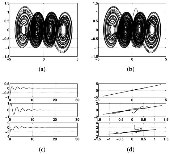
Figure 16.
Master–slave synchronization of two four-scroll chaotic attractors with : (a) master oscillator; (b) slave oscillator; (c) error synchronization; and (d) error phase diagram for the states of the master x and the slave .
The proposed scheme for the synchronization of multi-scroll chaotic oscillators of the form shown in Equation (3) using OTAs is shown in Figure 17. The vector K in Equation (7) is the observer gain and it is adjusted by selecting the value of the OTA according to the sufficient conditions for synchronization given in []. In all our simulations, the values of the transconductances were evaluated as: A/V, and we used the values for from the cases listed in Table 1 for the PSO algorithm. Those values are tuned from the OTAs with these equations: , , , and .
Figure 17.
Synchronization of two multi-scroll chaotic attractors implemented with OTAs and with our proposed current mode PWL function described by the block SNLF.
6. Layout and Post-Layout Simulations of the Synchronization of Two Multi-Scroll Chaotic Oscillators
The layout of our proposed CMOS programmable current-mode PWL function in Figure 6 is shown in Figure 18. It is used in the complete layout of the OTA-based CMOS multi-scroll chaotic oscillator shown in Figure 19. The dimension of the silicon area is m × 350 m. A total of 2005 elements and 175 nodes were required, and a total of 21 inputs/outputs were considered to design the pad frame that contains a protection diode, Vdd, Vss and open contacts to connect the manufactured designs.
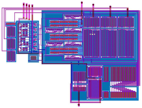
Figure 18.
Proposed SNLF Blocks Layout.
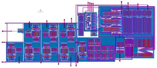
Figure 19.
Multi-scroll chaotic oscillator layout
The layout of the CMOS multi-scroll chaotic oscillator was designed by using Tanner suite version 16.2, and the post-layout simulations demonstrate that effectively we can program the proposed CMOS current-mode PWL function to generate 2–7 scrolls, as shown in Figure 20. External integration capacitances are used to control the spectra scaling of the system. A 0.5 pF parasitic capacitance and an inductor have been introduced in the simulation at the outputs of the state variables, which resemble the internal IC parasitic elements of the circuit and the pad frame.
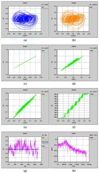
Figure 20.
Post-layout simulation for the synchronization of two seven-scroll chaotic oscillators with optimized MLE: (a) master oscillator showing vs. ; (b) slave oscillator showing vs. ; (c) synchronization of vs. ; (d) synchronization of vs. ; (e) synchronization of vs. ; (f) SNLF to generate seven-scroll; (g) synchronization error ; and (h) FFT analysis of showing Khz.
A 20 pF parasitic capacitance associated to an oscilloscope was included at the outputs of the state variables, and an external integrator capacitance of was used, calculated to correspond to a 636.62 kHz dominant frequency. Higher frequencies of chaotic oscillation can be reached using bipolar technology [] to compete with digital implementations []. In Figure 20, it can be seen the good synchronization for all the cases when plotting the state variables of the master oscillator x vs. the slave oscillator . This leads us to conclude that these multi-scroll chaotic attractors are robust to PVT variations, they allow programmability to generate 2–7 scrolls, and therefore are quite suitable for the development of applications like chaotic secure communication systems.
7. Conclusions
We have introduced a new CMOS current-mode programmable PWL function using 0.35 m CMOS technology of AMS. It is used to design a CMOS chaotic oscillator that can be programmed to generate 2–7-scroll attractors. The coefficients of this chaotic oscillator were tuned by designing programmable OTAs. Using two chaotic oscillators, we showed the implementation of a synchronized master–slave topology, performed by generalized Hamiltonian forms and observer approach.
It was highlighted that the required PWL function, considered as a saturated nonlinear function (SNLF) series, can be implemented in current-mode, and one can take control of the break-points and slopes of the linear segments. The simulation results showed that our CMOS multi-scroll chaotic oscillator is robust to PVT variations. Finally, the simulations performed after the layout parasitic extraction, and the five PVT corner analysis and four temperatures (−20 C, 20 C, 60 C and 100 C), demonstrate the suitability of our proposed CMOS chaotic oscillator to be used in engineering applications, such as chaotic secure communication systems, healthcare informatics, security, Internet of Things, and so on. These practical applications require low-power consuming circuits, such as our proposed CMOS chaotic oscillator that is also quite suitable to enhance wireless systems.
Author Contributions
Investigation, V.H.C.-G., E.T.-C., C.S.-L. and F.V.F.-F.; and Writing—review and editing, V.H.C.-G., E.T.-C. and C.S.-L.
Funding
This work was supported in part by the National Council for Science and Technology (CONACyT/ Mexico), under Grants 237991 and 222843; in part by Universidad Autónoma de Tlaxcala (UATx), Tlaxcala de Xicohtencatl, TL, Mexico, under Grant CACyPI-UATx-2017; and by the Program to Strengthen Quality in Educational Institutions, under Grant C/PFCE-2016-29MSU0013Y-07-23.
Conflicts of Interest
The authors declare no conflict of interest. The founding sponsors had no role in the design of the study; in the collection, analyses, or interpretation of data; in the writing of the manuscript, or in the decision to publish the results.
References
- Pecora, L.M.; Carroll, T.L. Synchronization in chaotic systems. Phys. Rev. Lett. 1990, 64, 821. [Google Scholar] [CrossRef] [PubMed]
- Cuomo, K.M.; Oppenheim, A.V. Circuit implementation of synchronized chaos with applications to communications. Phys. Rev. Lett. 1993, 71, 65. [Google Scholar] [CrossRef] [PubMed]
- Sira-Ramirez, H.; Cruz-Hernández, C. Synchronization of chaotic systems: A generalized Hamiltonian systems approach. Int. J. Bifurc. Chaos 2001, 11, 1381–1395. [Google Scholar] [CrossRef]
- Dachselt, F.; Schwarz, W. Chaos and cryptography. IEEE Trans. Circuits Syst. I Fund. Theory Appl. 2001, 12, 1498–1509. [Google Scholar] [CrossRef]
- Yu, S.; Ma, Z.; Qiu, S.; Peng, S.; Lin, Q. Generation and synchronization of n-scroll chaotic and hyperchaotic attractors in fourth order systems. Chin. Phys. 2004, 317–328. [Google Scholar]
- Stavroulakis, P. Chaos Applications in Telecommunications; CRC Press: Boca Raton, FL, USA, 2005. [Google Scholar]
- Kapitaniak, T. Chaos for Engineers: Theory, Applications, and Control; Springer Science & Business Media: Berlin, Germany, 2012. [Google Scholar]
- Goldberger, A.L. Nonlinear dynamics, fractals and chaos: Applications to cardiac electrophysiology. Ann. Biomed. Eng. 1990, 18, 195–198. [Google Scholar] [CrossRef] [PubMed]
- Tsonis, A.A. Chaos: From Theory to Applications; Springer Science & Business Media: Berlin, Germany, 2012. [Google Scholar]
- Degn, H.; Holden, A.V.; Olsen, L.F. Chaos in Biological Systems; Springer Science & Business Media: Berlin, Germany; Volume 138, 2013. [Google Scholar]
- Weller, R. Resistance, Chaos and Control in China: Taiping Rebels, Taiwanese Ghosts and Tiananmen; Springer: Berlin, Germany, 2013. [Google Scholar]
- Strogatz, S.H. Nonlinear Dynamics and Chaos: With Applications to Physics, Biology, Chemistry, and Engineering; Westview Press: Boulder, CO, USA, 2014. [Google Scholar]
- Ditto, W.L.; Sinha, S. Exploiting chaos for applications. Chaos Interdisciplin. J. Nonlinear Sci. 2015, 25, 097615. [Google Scholar] [CrossRef] [PubMed]
- Trejo-Guerra, R.; Tlelo-Cuautle, E.; Carbajal-Gómez, V.H.; Rodriguez-Gomez, G. A survey on the integrated design of chaotic oscillators. Appl. Math. Comput. 2013, 219, 5113–5122. [Google Scholar] [CrossRef]
- Delgado-Restituto, M.; Rodríguez-Vázquez, A. Design considerations for integrated continuous-time chaotic oscillators. IEEE Trans. Circuits Syst. I Fund. Theory Appl. 1998, 45, 481–495. [Google Scholar] [CrossRef]
- Rodríguez-Vázquez, A.; Delgado-Restituto, M. CMOS design of chaotic oscillators using state variables: A monolithic Chua’s circuit. IEEE Trans. Circuits Syst. II Analog Dig. Signal Process. 1993, 40, 596–613. [Google Scholar] [CrossRef]
- Tlelo-Cuautle, E.; Gaona-Hernández, A.; García-Delgado, J. Implementation of a chaotic oscillator by designing Chua’s diode with CMOS CFOAs. Analog Integr. Circuits Signal Process. 2006, 48, 159–162. [Google Scholar] [CrossRef]
- Sánchez-López, C.; Castro-Hernández, A.; Pérez-Trejo, A. Experimental verification of the Chua’s circuit designed with UGCs. IEICE Electron. Express 2008, 5, 657–661. [Google Scholar] [CrossRef]
- Trejo-Guerra, R.; Tlelo-Cuautle, E.; Sánchez-López, C.; Munoz-Pacheco, J.; Cruz-Hernández, C. Realization of multiscroll chaotic attractors by using current-feedback operational amplifiers. Rev. Mex. Fis. 2010, 56, 268–274. [Google Scholar]
- Sanchez-Lopez, C.; Tlelo-Cuautle, E.; Carrasco-Aguilar, M.; Morales-López, F.; Cante-Michcol, B. Multi-scroll chaotic oscillator employing UGCs. In Proceedings of the International Conference on Electrical, Communications, and Computers, Cholula, Mexico, 26–29 February 2009; pp. 189–191. [Google Scholar]
- Muñoz-Pacheco, J.M.; Zambrano-Serrano, E.; Félix-Beltrán, O.; Gómez-Pavón, L.C.; Luis-Ramos, A. Synchronization of PWL function-based 2D and 3D multi-scroll chaotic systems. Nonlinear Dyn. 2012, 70, 1633–1643. [Google Scholar] [CrossRef]
- Munoz-Pacheco, J.; Tlelo-Cuautle, E. Electronic Design Automation of Multi-Scroll Chaos Generators; Bentham Sciences Publishers: Dubai, UAE, 2010. [Google Scholar]
- Muñoz-Pacheco, J.; Tlelo-Cuautle, E. Automatic synthesis of 2D-n-scroll chaotic systems by behavioral modeling. J. Appl. Res. Technol. 2009, 7, 5–14. [Google Scholar]
- Zhou, T.; Chen, G. Classification of chaos in 3-D autonomous quadratic systems-I: Basic framework and methods. Int. J. Bifurc. Chaos 2006, 16, 2459–2479. [Google Scholar] [CrossRef]
- Varrientos, J.E.; Sánchez-Sinencio, E. A 4-D chaotic oscillator based on a differential hysteresis comparator. IEEE Trans. Circuits Syst. I Fund. Theory Appl. 1998, 45, 3–10. [Google Scholar] [CrossRef]
- Lü, J.; Chen, G. Generating multiscroll chaotic attractors: theories, methods and applications. Int. J. Bifurc. Chaos 2006, 16, 775–858. [Google Scholar] [CrossRef]
- Trejo-Guerra, R.; Tlelo-Cuautle, E.; Jiménez-Fuentes, M.; Muñoz-Pacheco, J.; Sánchez-López, C. Multiscroll floating gate–based integrated chaotic oscillator. Int. J. Circuit Theory Appl. 2013, 41, 831–843. [Google Scholar] [CrossRef]
- Trejo-Guerra, R.; Tlelo-Cuautle, E.; Jiménez-Fuentes, J.; Sánchez-López, C.; Muñoz-Pacheco, J.; Espinosa-Flores-Verdad, G.; Rocha-Pérez, J. Integrated circuit generating 3-and 5-scroll attractors. Commun. Nonlinear Sci. Numer. Simul. 2012, 17, 4328–4335. [Google Scholar] [CrossRef]
- de la Fraga, L.G.; Tlelo-Cuautle, E.; Carbajal-Gómez, V.; Munoz-Pacheco, J. On maximizing positive Lyapunov exponents in a chaotic oscillator with heuristics. Rev. Mex. Fis 2012, 58, 274–281. [Google Scholar]
- Carbajal-Gómez, V.H.; Tlelo-Cuautle, E.; Fernández, F.V. Optimizing the positive Lyapunov exponent in multi-scroll chaotic oscillators with differential evolution algorithm. Appl. Math. Comput. 2013, 219, 8163–8168. [Google Scholar] [CrossRef]
- de la Fraga, L.G.; Tlelo-Cuautle, E. Optimizing the maximum Lyapunov exponent and phase space portraits in multi-scroll chaotic oscillators. Nonlinear Dyn. 2014, 76, 1503–1515. [Google Scholar] [CrossRef]
- Carbajal-Gómez, V.; Tlelo-Cuautle, E.; Fernández, F.; de la Fraga, L.; Sánchez-López, C. Maximizing Lyapunov Exponents in a Chaotic Oscillator by Applying Differential Evolution. Int. J. Nonlinear Sci. Numer. Sim. 2014, 15, 11–17. [Google Scholar] [CrossRef]
- Wolf, A.; Swift, J.B.; Swinney, H.L.; Vastano, J.A. Determining Lyapunov exponents from a time series. Phys. D Nonlinear Phenom. 1985, 16, 285–317. [Google Scholar] [CrossRef]
- Barna, G.; Tsuda, I. A new method for computing Lyapunov exponents. Phys. Lett. A 1993, 175, 421–427. [Google Scholar] [CrossRef]
- Dieci, L. Jacobian free computation of Lyapunov exponents. J. Dyn. Differ. Equ. 2002, 14, 697–717. [Google Scholar] [CrossRef]
- Rugonyi, S.; Bathe, K.J. An evaluation of the Lyapunov characteristic exponent of chaotic continuous systems. Int. J. Numer. Methods Eng. 2003, 56, 145–163. [Google Scholar] [CrossRef]
- Chen, Z.M.; Djidjeli, K.; Price, W. Computing Lyapunov exponents based on the solution expression of the variational system. Appl. Math. Comput. 2006, 174, 982–996. [Google Scholar] [CrossRef]
- Yang, C.; Zhu, W.; Ren, G. Approximate and efficient calculation of dominant Lyapunov exponents of high-dimensional nonlinear dynamic systems. Commun. Nonlinear Sci. Numer. Simul. 2013, 18, 3271–3277. [Google Scholar] [CrossRef]
- Banks, J.; Brooks, J.; Cairns, G.; Davis, G.; Stacey, P. On Devaney’s definition of chaos. Am. Math. Mon. 1992, 99, 332–334. [Google Scholar] [CrossRef]
- Cook, P. Nonlinear Dynamical Systems; Prentice Hall: Upper Saddle River, NJ, USA, 1994. [Google Scholar]
- Parker, T.S.; Chua, L.O. Practical Numerical Algorithms for Chaotic Systems; Springer: New York, NY, USA, 1989. [Google Scholar]
- Hoppensteadt, F.C. Analysis and Simulation of Chaotic Systems; Springer: Berlin, Germany, 2000. [Google Scholar]
- Birta, L.G.; Arbez, G. Modelling and Simulation: Exploring Dynamic System Behaviour; Springer: Berlin, Germany, 2007. [Google Scholar]
- Zelinka, G.; Chen, S. Chaos synthesis by means of evolutionary algorithms. Int. J. Bifurc. Chaos 2008, 18, 911–942. [Google Scholar] [CrossRef]
- Gálvez, A. Numerical-Symbolic MATLAB Program for the analysis of three-dimensional chaotic systems. In International Conference on Computational Science; Springer: Berlin/Heidelberg, Germany, 2007; pp. 211–218. [Google Scholar]
- Li, S.; Mou, X.; Cai, Y.; Ji, Z.; Zhang, J. On the security of a chaotic encryption scheme: Problems with computerized chaos in finite computing precision. Comput. Phys. Commun. 2003, 153, 52–58. [Google Scholar] [CrossRef]
- Lü, J.; Chen, G. Design and Analysis of Multiscroll Chaotic Attractors From Saturated Function Series. IEEE Trans. Circuits Syst. 2004, 51, 2476–2490. [Google Scholar] [CrossRef]
- Lü, J.; Yu, S.; Leung, H.; Chen, G. Experimental verification for 3-D hysteresis multiscroll chaotic attractors. In Proceedings of the IEEE International Symposium on Circuits and Systems (ISCAS’05), Kobe, Japan, 23–26 May 2005. [Google Scholar]
- Schuster, H.G.; Just, W. Deterministic Chaos: An Introduction; John Wiley & Sons: Hoboken, NJ, USA, 2006. [Google Scholar]
- Grigoras, V.; Grigoras, C. Digital Data Encryption Based on Discrete Additive Systems. In Topics on Chaotic Systems, Selected Papers from CHAOS 2008 International Conference; World Scientific Publishing Co. World Scientific: Singapore, 2009; pp. 149–157. [Google Scholar]
- Carbajal-Gómez, V.H.; Tlelo-Cuautle, E.; Fernández, F.V. Application of Computational Intelligence Techniques to Maximize Unpredictability in Multiscroll Chaotic Oscillators. In Computational Intelligence in Analog and Mixed-Signal (AMS) and Radio-Frequency (RF) Circuit Design; Springer: Berlin, Germany, 2015; pp. 59–81. [Google Scholar]
- Trejo-Guerra, R.; Tlelo-Cuautle, E.; Munoz-Pacheco, J.; Sánchez-López, C.; Cruz-Hernández, C. On the Relation between the Number of Scrolls and the Lyapunov Exponents in PWL-functions-based η-Scroll Chaotic Oscillators. Int. J. Nonlinear Sci. Numer. Simul. 2010, 11, 903–910. [Google Scholar] [CrossRef]
- Chua, L.O. Introduction to Nonlinear Network Theory; McGraw-Hill: New York, NY, USA, 1969. [Google Scholar]
- Chua, L. Computer-Aided Analysis of Electronic Circuits: Algorithms and Computational Techniques; Prentice Hall: Upper Saddle River, NJ, USA, 1975. [Google Scholar]
- Chien, M.J.; Kuh, E.S. Solving nonlinear resistive networks using piecewise-linear analysis and simplicial subdivision. IEEE Trans. Circuits Syst. 1977, 24, 305–317. [Google Scholar] [CrossRef]
- Bazaraa, M.S.; Sherali, H.D.; Shetty, C.M. Nonlinear Programming: Theory and Algorithms; John Wiley & Sons: Hoboken, NJ, USA, 2013. [Google Scholar]
- Dar, M.R.; Kant, N.A.; Khanday, F.A. Realization of Integrable Incommensurate-Fractional-Order-Rössler- System Design Using Operational Transconductance Amplifiers (OTAs) and Its Experimental Verification. Int. J. Bifurc. Chaos 2017, 27, 1750077. [Google Scholar] [CrossRef]
- Carroll, T.L.; Pecora, L.M. Synchronizing chaotic circuits. IEEE Trans. Circuits Syst. 1991, 38, 453–456. [Google Scholar] [CrossRef]
- Zeng, Y.; Singh, S.N. Adaptive control of chaos in Lorenz system. Dyn. Control 1997, 7, 143–154. [Google Scholar] [CrossRef]
- Agiza, H.; Yassen, M. Synchronization of Rossler and Chen chaotic dynamical systems using active control. Phys. Lett. A 2001, 278, 191–197. [Google Scholar] [CrossRef]
- Kocarev, L. Chaos-based cryptography: A brief overview. IEEE Circuits Syst. Mag. 2001, 1, 6–21. [Google Scholar] [CrossRef]
- Yassen, M. Adaptive control and synchronization of a modified Chua’s circuit system. Appl. Math. Comput. 2003, 135, 113–128. [Google Scholar] [CrossRef]
- Huang, L.; Feng, R.; Wang, M. Synchronization of chaotic systems via nonlinear control. Phys. Lett. A 2004, 320, 271–275. [Google Scholar] [CrossRef]
- Yassen, M. Chaos synchronization between two different chaotic systems using active control. Chaos Solitons Fractals 2005, 23, 131–140. [Google Scholar] [CrossRef]
- Guyeux, C.; Bahi, J. A new chaos-based watermarking algorithm. In Proceedings of the 2010 International Conference on Security and Cryptography (SECRYPT), Athens, Greece, 26–28 July 2010; pp. 455–458. [Google Scholar]
- Volos, C.; Kyprianidis, I.; Stouboulos, I.; Pham, V.T. Radio Frequency Chaotic Circuit Design: From Theory to Practice. In Performance Optimization Techniques in Analog, Mixed-Signal, and Radio-Frequency Circuit Design; IGI Global: Hershey, PA, USA, 2014; p. 364. [Google Scholar]
- Rulkov, N.F.; Sushchik, M.M.; Tsimring, L.S.; Abarbanel, H.D. Generalized synchronization of chaos in directionally coupled chaotic systems. Phys. Rev. E 1995, 51, 980. [Google Scholar] [CrossRef]
- Efremova, E.V.; Dmitriev, A.S. Ultrawideband Microwave 3-to-7 GHz Chaotic Oscillator Implemented as SiGe Integrated Circuit. In Emergent Complexity from Nonlinearity, in Physics, Engineering and the Life Sciences; Mantica, G., Stoop, R., Stramaglia, S., Eds.; Springer International Publishing: Cham, Switzerland, 2017; pp. 71–80. [Google Scholar]
- Karimov, T.I.; Butusov, D.N.; Pesterev, D.O.; Predtechenskii, D.V.; Tedoradze, R.S. Quasi-chaotic mode detection and prevention in digital chaos generators. In Proceedings of the 2018 IEEE Conference of Russian Young Researchers in Electrical and Electronic Engineering (EIConRus), Moscow, Russia, 29 January–1 February 2018; pp. 303–307. [Google Scholar]
© 2018 by the authors. Licensee MDPI, Basel, Switzerland. This article is an open access article distributed under the terms and conditions of the Creative Commons Attribution (CC BY) license (http://creativecommons.org/licenses/by/4.0/).