1. Introduction
The enhancement of speech corrupted by background noise represents a great challenge for real-word speech processing systems, such as speech recognition, speaker identification, voice coders, hand-free systems, and hearing aids. The main purpose of speech enhancement is to improve the perceptual quality and intelligibility of speech by using various noise reduction algorithms.
Spectral subtraction method is a popular single-channel noise reduction algorithm that has been initially proposed for speech enhancement [
1]. This basic spectral subtraction method can substantially reduce the noise level, but it is accompanied by an annoying noise in the enhanced speech signal, named musical noise. A generalized version of this method has been proposed to reduce the residual musical noise by an over-subtraction of the noise power [
2]. The multi-band algorithm has been developed to reduce additive colored noise that does not uniformly affect the entire frequency band of useful speech signal [
3]. Improved version based on multi-band Bark scale frequency spacing has been also proposed to reduce the colored noise [
4]. An adaptive noise estimate for each band has been proposed [
5]. Furthermore, the spectral subtraction approach has also been applied to other kinds of sounds such as underwater acoustic sounds [
6], machine monitoring [
7,
8], hearing aid [
9], pulmonary sounds [
10,
11,
12], etc.
In real-world applications, such as hands-free communication kits, cellular phones and hearing aid devices, these speech enhancement techniques need to be executed in real-time. Hardware implementation of this kind of algorithms is a difficult task that consists in finding a balance between complexity, efficiency and throughput of these algorithms. Architectures based on the spectral subtraction approach have been implemented on Field Programmable Gate Array (FPGA) devices [
13,
14,
15,
16,
17,
18,
19]. However, these architectures perform a uniform spectral subtraction over the entire frequency band and, therefore, they do not efficiently suppress colored noise.
In this paper, a new pipelined architecture of multi-band spectral subtraction method has been proposed for real-time speech enhancement. The proposed architecture has been implemented on FPGA using the Xilinx System Generator (Xilinx Inc, San Diego, CA, USA) programming tool and the Nexys-4 (Digilent Inc, Pullman, WA, USA) development board build around an Artix-7 XC7A100T FPGA chip (Xilinx Inc, San Diego, CA, USA). Mathematical equations describing this speech enhancement algorithm (Fourier transform, signal power spectrum, noise power estimate, multi-band separation, signal-to-noise ratio, over-subtraction factor, spectral subtraction, multi-band merging, inverse Fourier transform, etc.) have been efficiently modeled using the XSG blockset. High-speed performance was obtained by inserting and redistributing the pipelining delays.
The rest of the paper is organized as following:
Section 2 presents the theory details of the spectral subtraction theory for speech enhancement.
Section 3 presents the XSG-based hardware system and discusses the details of different subsystems. Speech enhancement performances are presented in
Section 4. Finally, conclusion and perspective are provided in
Section 5.
2. Spectral Subtraction Methods
In the additive noise model, it is assumed that the discrete-time noisy signal
is composed of the clean signal
and the uncorrelated additive noise
.
where
n is the discrete-time index.
Since the Fourier transform is linear, this relation is also additive in the frequency domain
where
,
and
are the discrete Fourier transform (DFT) of
,
and
, respectively, and
k is the discrete-frequency index. In practice, the spectral subtraction algorithm operates on a short-time signal, by dividing the noisy speech
into frames of size
N. Then, the discrete Fourier transform is applied on each frame. The frequency resolution depends both on the sampling frequency
and the length of the frame in samples
N. The discrete frequencies are defined by
for
, and by
for
. As a complex function, the Fourier transform of the corrupted signal can be represented by its rectangular form
, where
and
are the real and imaginary part of
, respectively. It can also be represented by its polar form
, where
and
are the magnitude and the phase of
, respectively.
2.1. Basic Spectral Substraction
In the spectral subtraction method, the spectrum of the enhanced speech is obtained by subtracting an estimate of noise spectrum from the noisy signal spectrum [
1]. To avoid negative magnitude spectrum, a simple half-wave rectifier has been first employed.
where the noise spectrum,
, is estimated during the non-speech segments.
To reconstruct the enhanced signal, its phase
is approximated by the phase
of the noisy signal. This is based on the fact that in human perception the short time spectral magnitude is more important than the phase [
4,
20]. Thus, the discrete Fourier transform (DFT) of the enhanced speech is estimated as
Finally, the enhanced speech is obtained by inverse discrete Fourier transform (IDFT).
However, this basic method suffers from a perceptually annoying residual noise named musical noise.
2.2. Generalized Spectral Subtraction
A generalized form of the spectral subtraction method has been suggested [
2] to minimize the residual musical noise. It consists of over-subtracting an estimate of the noise power spectrum and ensuring that the resulting spectrum does not fall below a predefined minimum level (spectral floor).
where
is the over-subtraction multiplication factor and
is the spectral flooring parameter [
2].
is the exponent determining the transition sharpness, where
corresponds to the magnitude spectral subtraction [
1] and
to the power spectral subtraction [
2].
To minimize the speech distortion produced by large values of
, it has been proposed to let
vary from frame to frame within speech signal [
2].
where
is the segmental signal-to-noise ratio estimated in the frame and defined by:
As for the basic method, the discrete Fourier transform of the enhanced signal
is calculated from the estimated magnitude
of the enhanced signal and the phase
of the corrupted input signal using (
4). The enhanced signal
is reconstructed by inverse discrete Fourier transform (
5).
2.3. Multi-Band Spectral Subtraction
The multi-band spectral subtraction method has been developed to reduce additive colored noise that does not uniformly affect the entire frequency band of the speech signal [
3]. In this method, both noisy speech and estimated noise spectra are divided into
M non-overlapping frequency bands. Then, the generalized spectral subtraction is applied independently in each band [
3]. The power spectrum estimate of the enhanced speech in the
ith frequency band is obtained as:
where
and
are the beginning and the ending frequency bins of the
ith frequency band (
),
is the over-subtraction factor of the
ith frequency band, and
is the tweaking factor of the
ith frequency band [
3]. The over-subtraction factor
is related to the segmental
of the
ith frequency band by:
The segmental
of the
ith frequency band is defined by:
where
and
are the beginning and the ending frequency bins of the
ith frequency band. It can also be expressed using the natural logarithmic function:
The tweaking factor
in (
9) can be used to have an additional degree of noise removing control in each frequency band. The values of
are experimentally defined and set to [
3]:
where
denotes frequency in the
ith band.
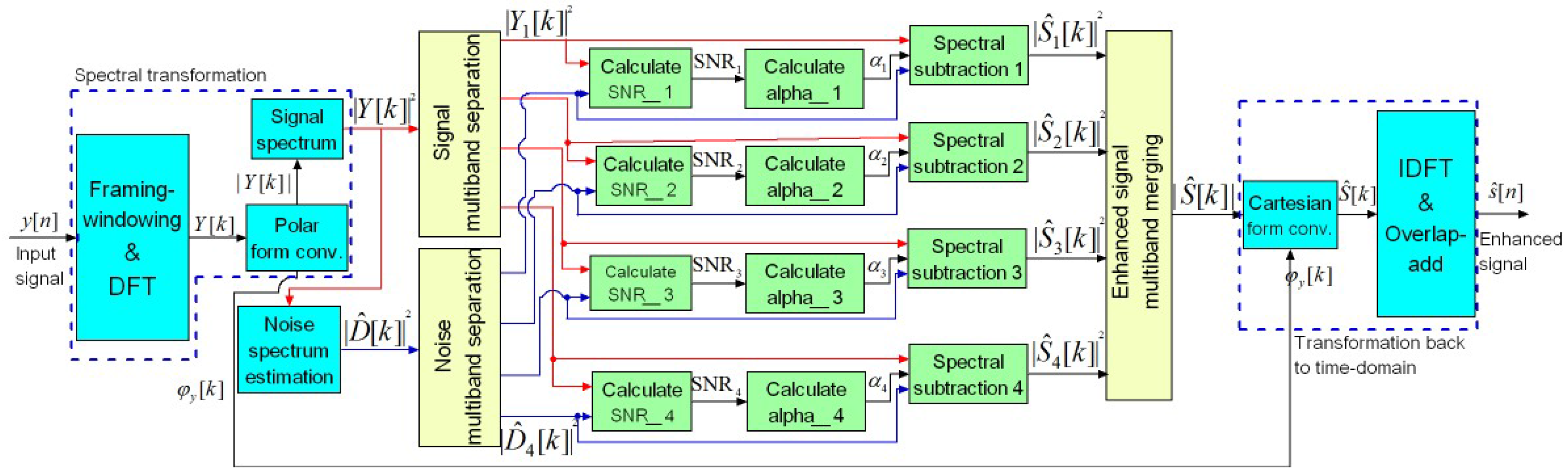
Figure 1 shows the block diagram of the speech enhancement system based on the multi-band spectral subtraction approach. Input noisy speech,
, is segmented into consecutive frames of
N samples before applying discrete Fourier transform (DFT). The magnitude,
, and phase,
, of the Fourier transformed signal are calculated. Then, spectrum of the noisy speech,
, is calculated for the current frame, while the spectrum of the noise,
, is estimated during non-speech segments. Both spectra are separated into (
) frequency bands of 1 kHz in width each, for a sampling frequency
. The segmental
and the over-subtraction factor
are calculated for each frequency band to allow independent spectral subtraction. The 4 separate spectra of the enhanced speech,
, are then merged and square root calculated to obtain
. Finally, the enhanced signal
is reconstructed by using inverse discrete Fourier transform (IDFT).
3. FPGA Implementation
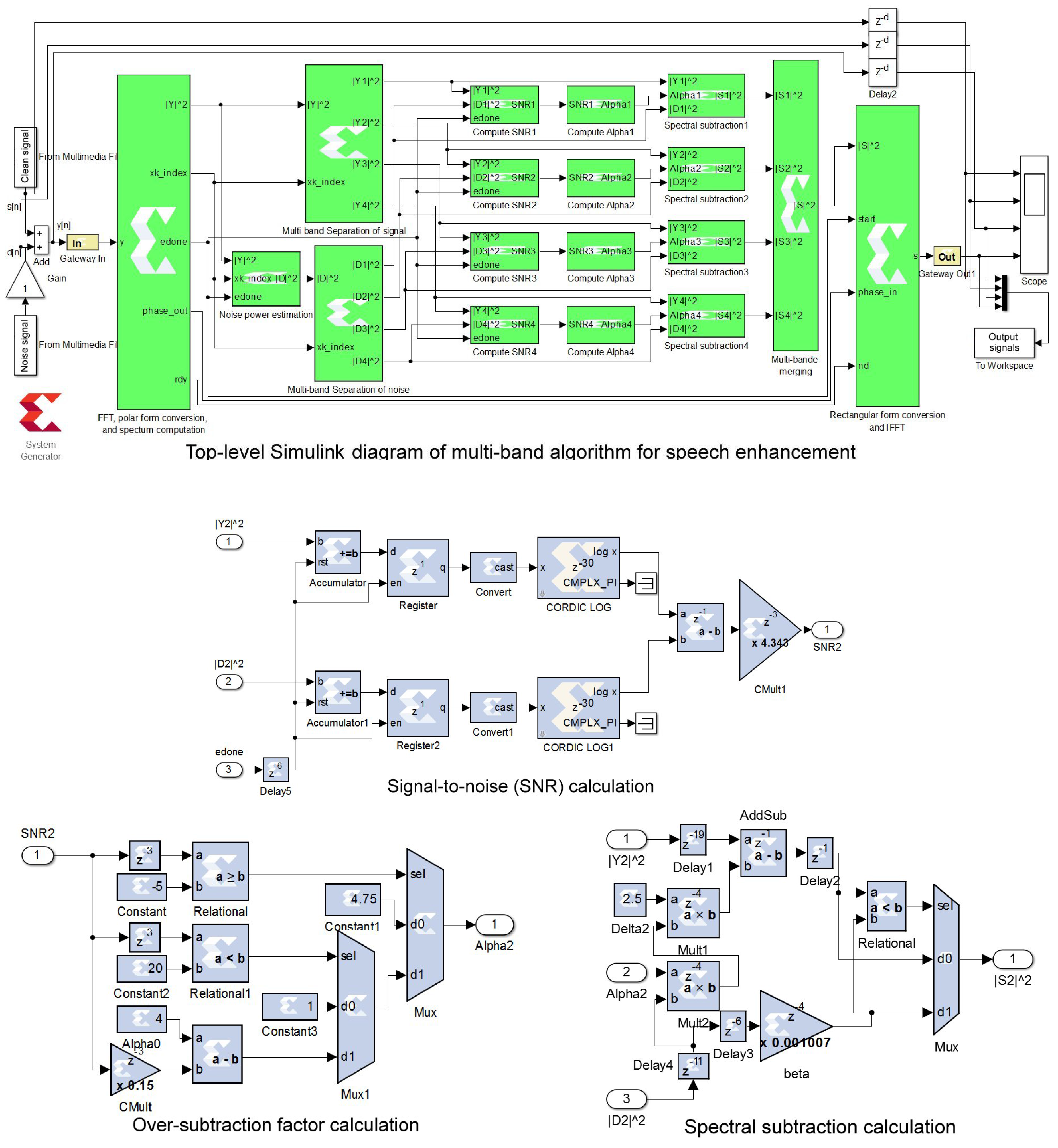
The proposed architecture has been implemented on a low-cost Artix-7 FPGA chip using a high-level programming tool (Xilinx System Generator), in MATLAB/SIMULINK (The Mathworks Inc., Natick, MA, USA) environment, and Nexys-4 development board. The top-level Simulink diagram of this architecture is presented in
Figure 2, which principally corresponds to the block diagram presented in
Figure 1. The proposed architecture uses some subsystems (blocks) developed in the past to implement, on an FPGA chip, the basic spectral subtraction method [
15]. However, only subsystems related to the multi-band approach will be described in details in the following subsections:
3.1. Spectral Transformation and Noise Spectrum Estimation
This step corresponds to the four left blue blocks in
Figure 1 and the two left XSG subsystems in
Figure 2. As described in [
15], the spectral analysis is performed by a Xilinx FFT (Fast Fourier Transform) block that provides the real,
, and imaginary,
, parts of the transformed signal
. It also provides the frequency index
k output and an output
done indicating that the computation of the Fourier transform of the current frame is complete and ready to output. Then, the Xilinx CORDIC (COordinate Rotation DIgital Computer) block is used to convert the transformed signal to its polar form, i.e., magnitude (
) and phase (
). A simple multiplier is used to calculate the power spectrum,
, of the noisy signal.
On the other hand, the power spectrum,
, of the additive noise is estimated using its average value calculated during the first five frames. A RAM (Random Access Memory)-based accumulator is used to estimate the noise power. More details on this subsystem can be found in [
15].
3.2. Multi-Band Separation of Signal and Noise
This step corresponds to the two left yellow blocks in
Figure 1 and their associated two subsystems in
Figure 2. The hardware implementation of this subsystem is done using four register (one per frequency band) having as input the signal power spectrum,
, and driven by the frequency index signal,
k. If
k belongs to the i
th frequency band, then the i
th register is enabled by
k, i.e.,
=
. Otherwise, it is reset, i.e.,
. For the i
th band, the frequency index
k is delimited by
and
, as in (
11) and (
12). The same subsystem is used to separate the noise power spectrum into linearly separated multi-band.
3.3. Signal-To-Noise (SNR) Estimator
This step corresponds to the four left green blocks in
Figure 1 and their associated four subsystems in
Figure 2. Considering the fact that Xilinx CORDIC block can calculate only the natural logarithm (ln) and not the decimal logarithm (log) function, the SNR subsystem has been implemented using (
12) instead of (
11). In addition, this approach permits avoiding the use of divider.
As shown in
Figure 2, this subsystem uses accumulators and registers to compute the sums for both signal and noise, followed by the CORDIC blocks to calculate their respective ln functions. After the subtractor block, the resulting value is multiplied by constant
.
3.4. Over-Subtraction Factor Calculation
This step corresponds to the four middle green blocks in
Figure 1 and their associated four subsystems in
Figure 2. Based on (
10), this subsystem is implemented using two multiplexers, two comparators, one subtractor, and constant blocks. The subsystem used in the 2nd frequency band is shown in
Figure 2.
3.5. Spectral Subtraction
This step corresponds to the four right green blocks in
Figure 1 and their associated four subsystems in
Figure 2. This subsystem is implemented using one comparator, one multiplexer, and three multipliers, according to (
9).
Figure 2 shows the subsystem used in the 2nd frequency band.
3.6. Multi-Band Merging
This step corresponds to the right yellow blocks in
Figure 1 and its associated subsystem in
Figure 2. The subsystem is implemented using tree Xilinx adder blocks to merge the spectra of the four sub-bands.
3.7. Transformation Back to Time-Domain
This step corresponds to the two right blue blocks in
Figure 1 and the right XSG subsystem in
Figure 2. The Fourier transform of the enhanced signal
is first converted to the rectangular form (to real,
, and imaginary,
, parts) using a Xilinx CORDIC block, then transformed back to time domain (
) using XSG IFFT (Inverse Fast Fourier Transform) block. More details on this subsystem can be found in [
15].
3.8. Pipelining
The pipelining consists in reducing the critical path delay by inserting delays into the computational elements (multipliers and adders) to increase the operating frequency (
Figure 2). The critical path corresponds to the longest computation time among all paths that contain zero delays [
21]. About 410 delays have been inserted in different paths and balanced to ensure synchronization. The proposed pipelining increased substantiality the operating frequency, but at the cost of the output latency of 36 samples. More details on how delays are inserted and redistributed can be found in our previous works [
21,
22].
3.9. Implementation Characteristics
Table 1 shows the hardware resources utilization, the maximum operating frequency, and the power consumption for the Artix-7 XC7A100T FPGA chip, as reported by Xilinx ISE 14.7 tool (Xilinx Inc, San Diego, CA, USA). The proposed pipelined architecture consumes 4955 logic slices from 15,850 available on this chip (31.2%). Also, it consumes 59 DSP48E1s from 240 available (24.6%). It occupies a small part of this low-cost FPGA. Therefore, the used resources consume about 107 mW. It can be noted that the pipelining of the implemented architecture increased the operating frequency from 24 MHz to 125 MHz, at the cost of an output latency of 36 delays. Therefore, the pipelined architecture requires more flip-flops (20,020 instead of 16,287) because of the inserted delays. Both default and pipelined architectures use the same number DSP48E1s and RAMB18E1s.
It can be noted that a 32-bit fixed-point format with 28 fractional bits has been globally used to quantify data. However, a 24-bit fixed-point format with 18 fractional bits has been sufficient to compute the over-subtraction factor and the segmental .
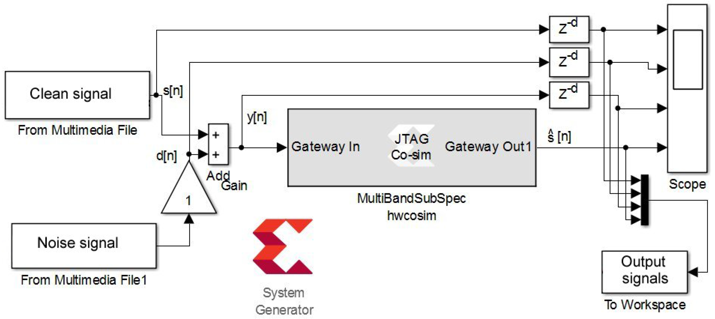
3.10. Hardware/Software Co-Simulation
Software simulation of the designed XSG-based model provides a faithful behavior to that performed on hardware (bit and cycle accurate modeling). This allows us to take full advantage of the simulation environment of SIMULINK to visualize intermediate signals and facilitate the tuning of the XSG block parameters in order to reach the desired performance. It also optimizes resources by choosing the number of bits needed to quantify data in different paths that ensures the needed performances. However, the designed XSG-based architecture can be executed on actual FPGA chip using the hardware-in-the-loop co-simulation from MATLAB/SIMULINK environment [
23]. A number of development boards are pre-configured on the XSG tool, but the Nexys-4 board is not included and must be configured manually. This compilation mode generates a bitstream file and its associate gray SIMULINK block (
Figure 3).
During the hardware/software co-simulation, the compiled model (bitstream file) is uploaded and executed on the FPGA chip from SIMULINK environment. XSG tool takes data from the input wav files in SIMULINK environment and transmits them to the design on the FPGA board using the JTAG (Joint Test Action Group) connection. It reads the enhanced signal (output) back from JTAG and sends it to SIMULINK for storage or display.
4. Results and Discussion
The proposed architecture has been tested on hardware using natural speech corrupted by artificial and actual additional noises, with sampling frequency of 8 kHz. The main objective of our experimental test is to validate the implementation process by ensuring that the hardware architecture (XSG) gives the same enhancement performances than the software simulation (MATLAB). Comparison of the multi-band spectral subtraction algorithm to other speech enhancement methods has been evaluated in the literature.
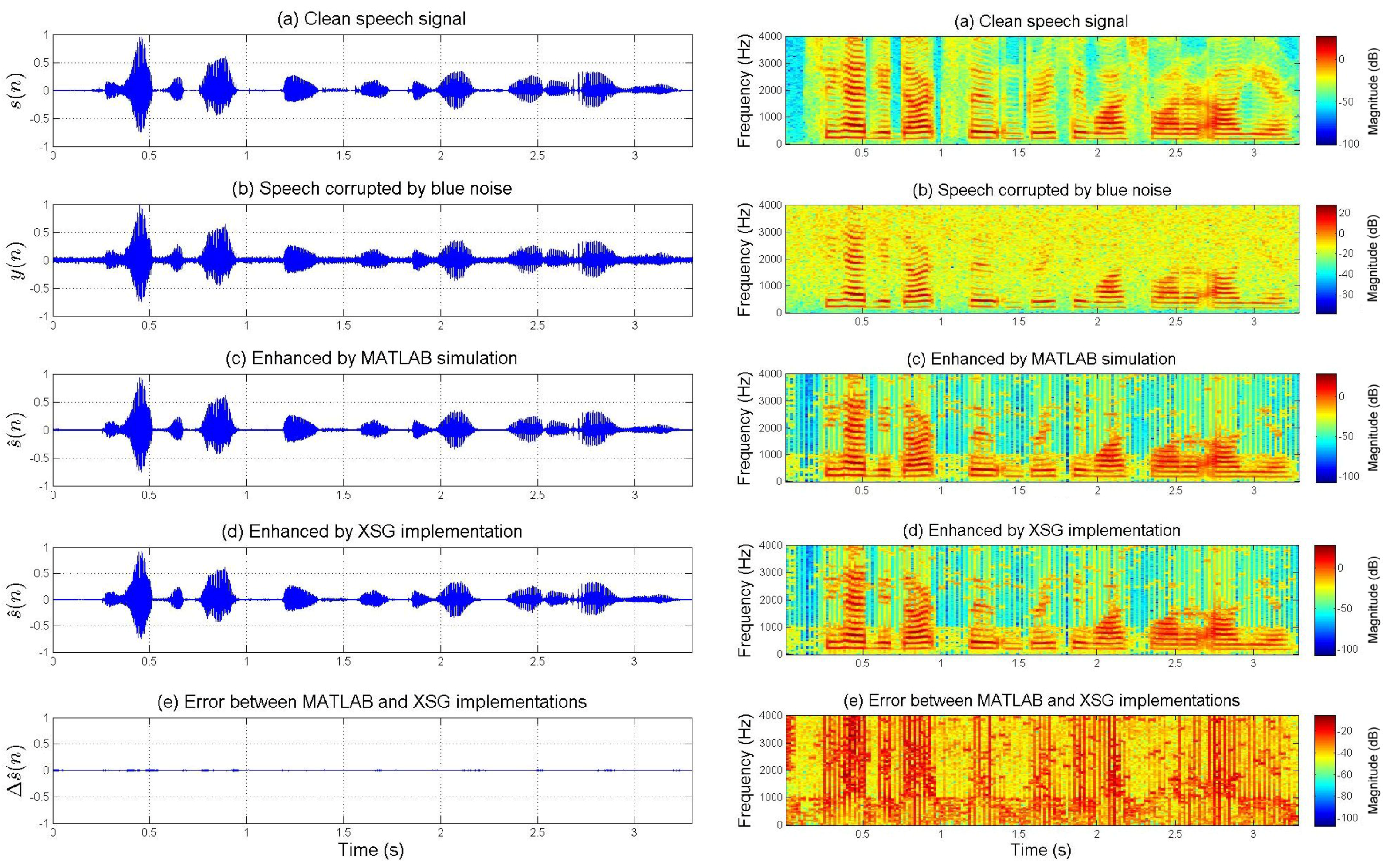
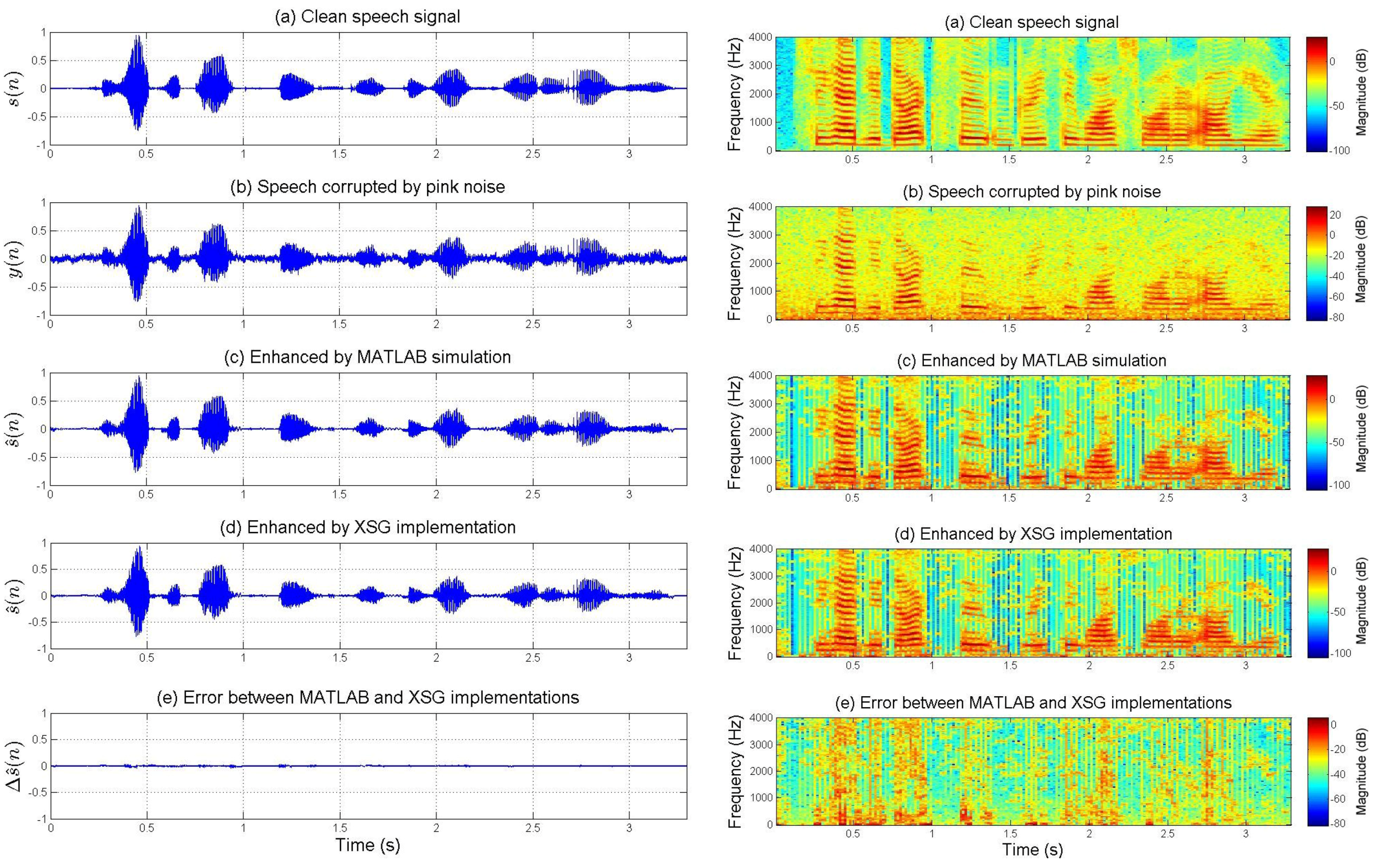
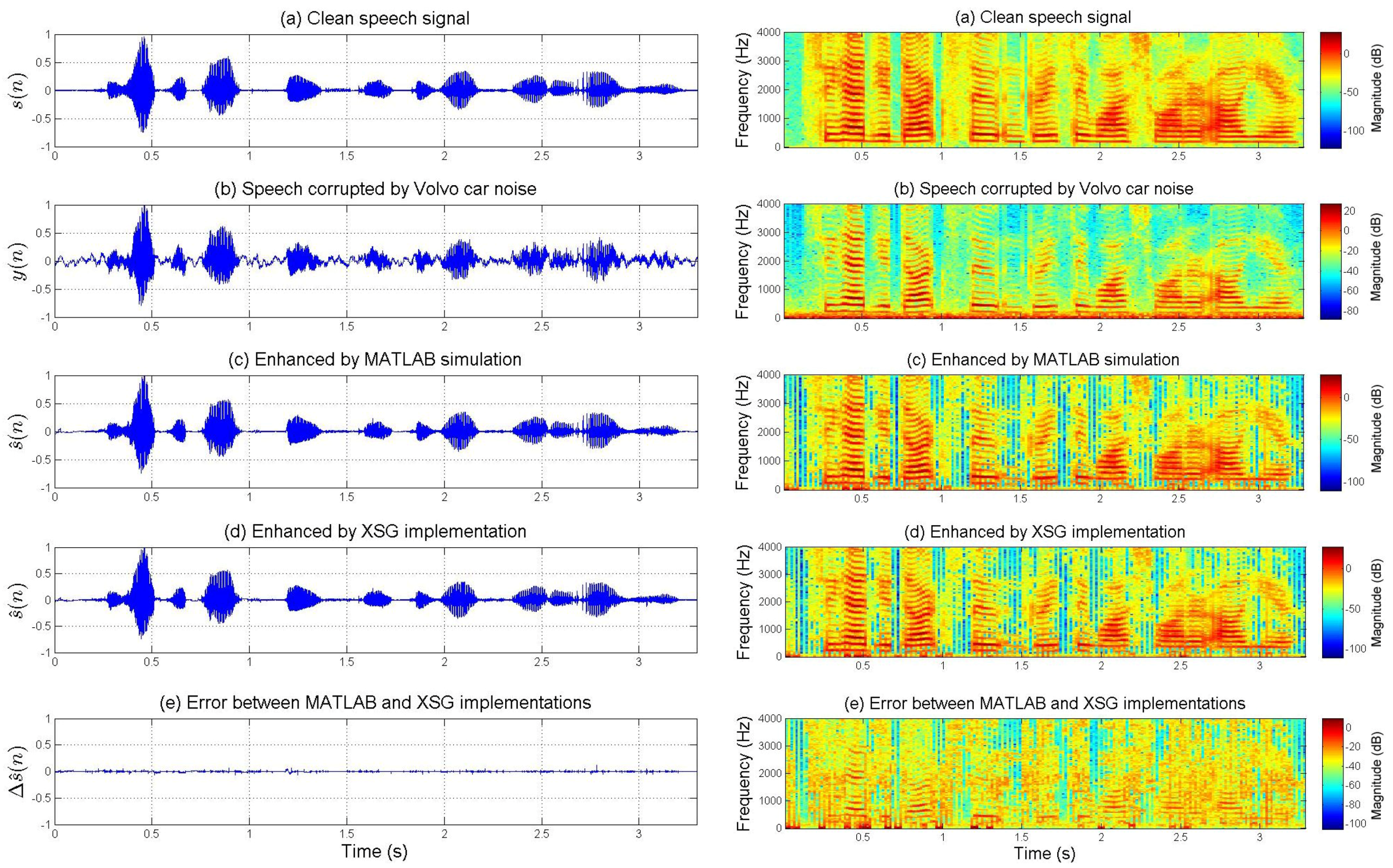
Figure 4 and
Figure 5 show the enhancement performances for speech corrupted by artificial blue and pink noises, respectively. However,
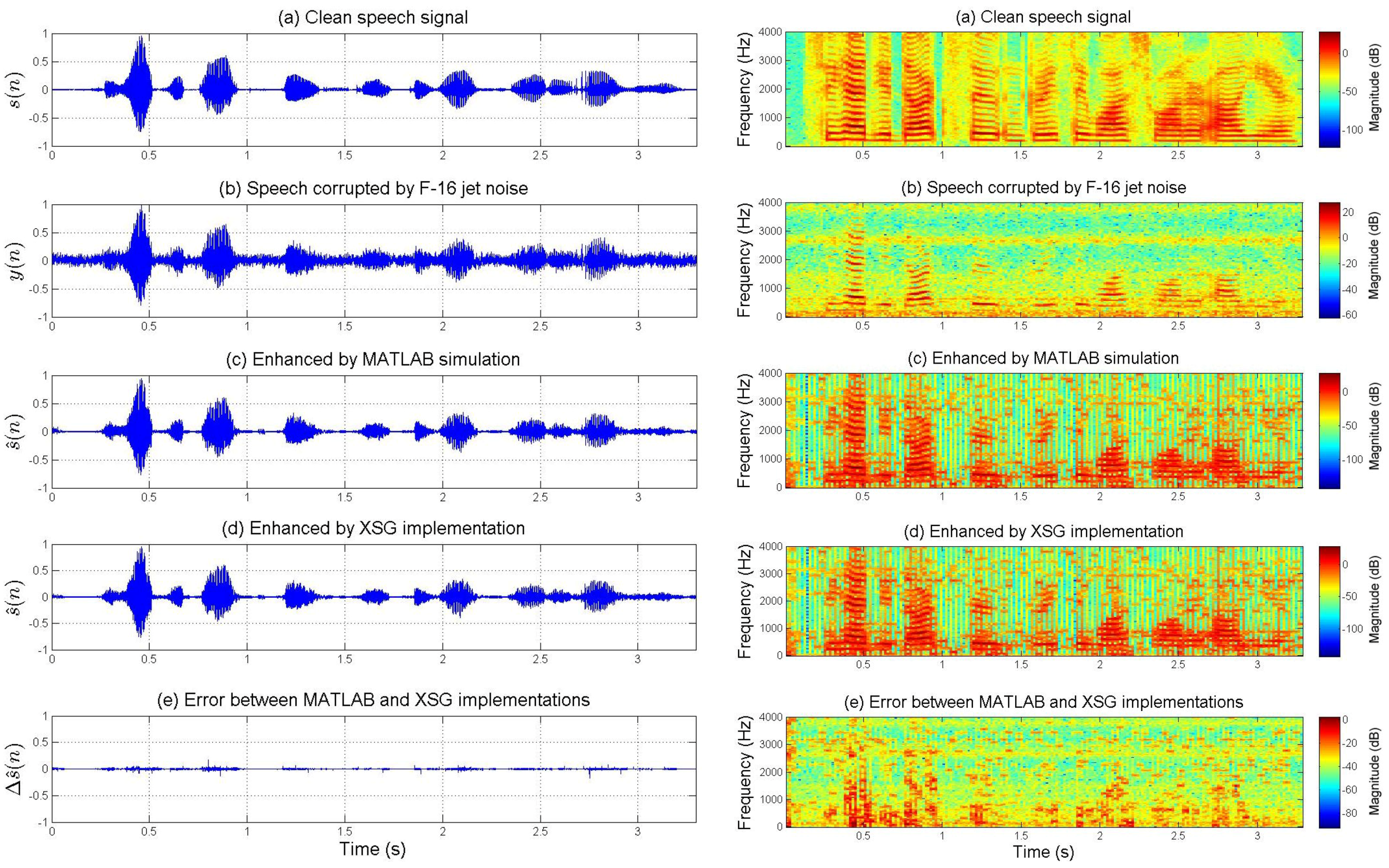
Figure 6 and
Figure 7 present the enhancement performances for speech corrupted by actual car and jet noises, respectively. The fixed-point XSG implementation of the multi-band spectral subtraction technique performs as well as the floating-point MATLAB simulation. Waveforms and spectrograms of the speech signals enhanced by hardware and software are similar. The experimental tests prove the accuracy of the FPGA-based implementation. It can be noted that noise was estimated during the first five frames.
On the other hand, the spectrograms of
Figure 4,
Figure 5,
Figure 6 and
Figure 7 show that the additive noises are removed despite the fact that they do not uniformly affect the frequency band of the speech. For each figure, the difference (error) between the signal enhanced by XSG-based architecture and the signal enhanced by MATLAB simulation has been represented with the same scale in the time-domain. Its time-frequency characteristics seem be close to those of a white noise (quantization noise).
The enhancement performances of the proposed XSG-based architecture are also compared to those obtained by MATLAB simulation using two objective tests: the overall signal-to-noise ratio () and the segmental signal-to-noise ratio ().
The overall signal-to-noise ratio (oveSNR) of the enhanced speech signal is defined by:
where
and
are the original and enhanced speech signals, respectively, and
L is the length of the entire signal in samples.
The segmental signal-to-noise ratio (segSNR) is calculated by averaging the frame-based SNRs over the signal.
where
M is the number of frames,
is the frame size, and
and
are the
m-th frame of original and enhanced speech signals, respectively.
Table 2 presents the objective tests for noisy and enhanced speech signals. The results obtained by the proposed XSG-based architecture are approximately similar to those obtained by MATLAB simulation. The minor differences between
and
can be explained by the quantification errors.


