
Developing an Affordable and Portable Control Systems Laboratory Kit with a Raspberry Pi †


Abstract
:
1. Introduction
1.1. Background
1.2. Motivation
2. Materials and Methods
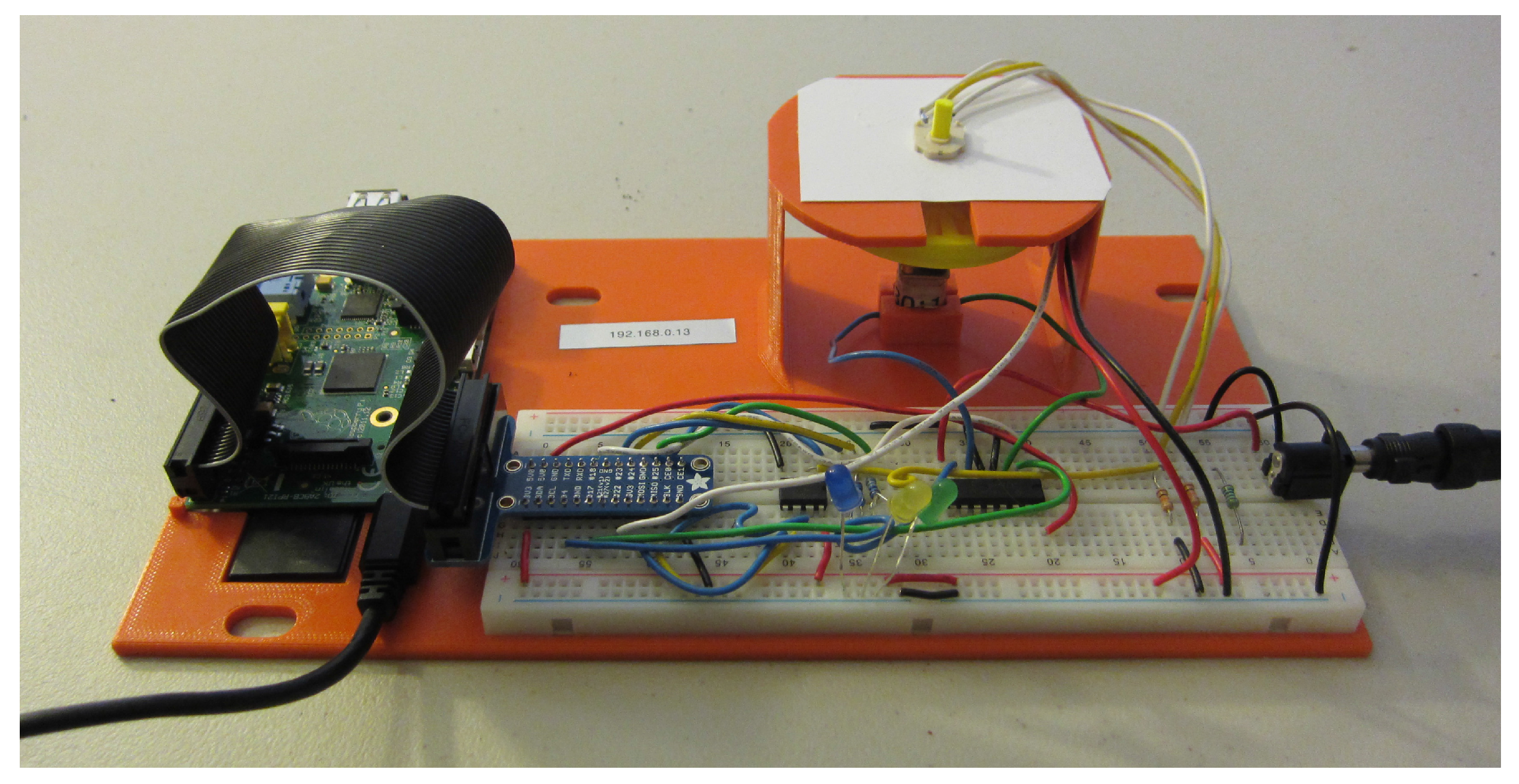
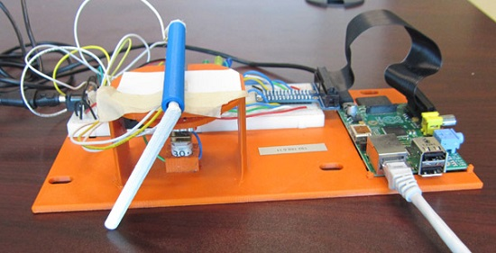
2.1. DC Motor Laboratory Kit Development
2.1.1. Raspberry Pi
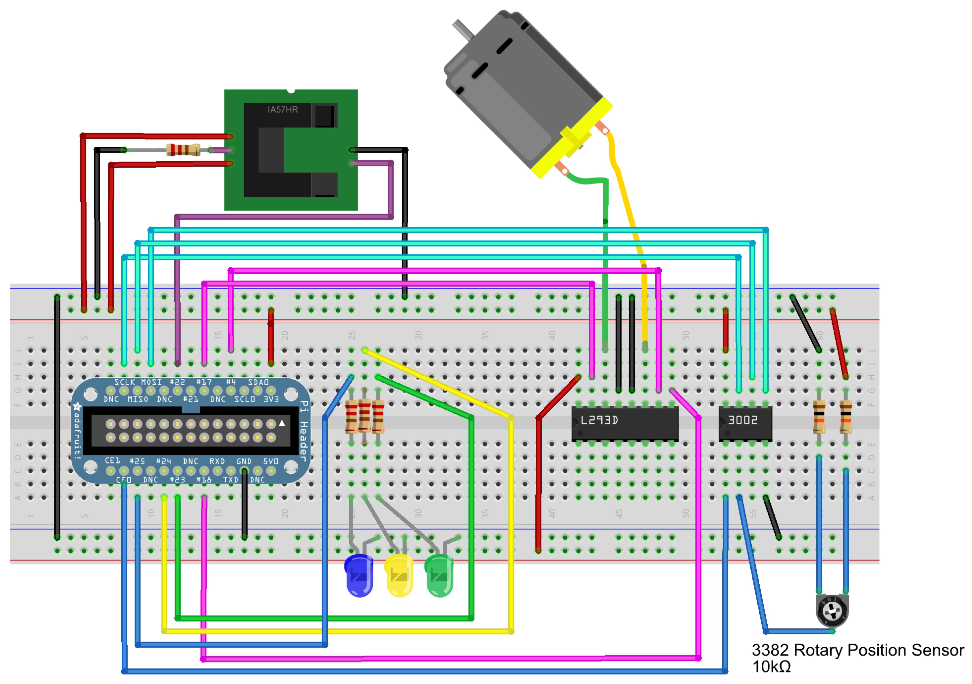
2.1.2. Circuits and Sensors
H-Bridge
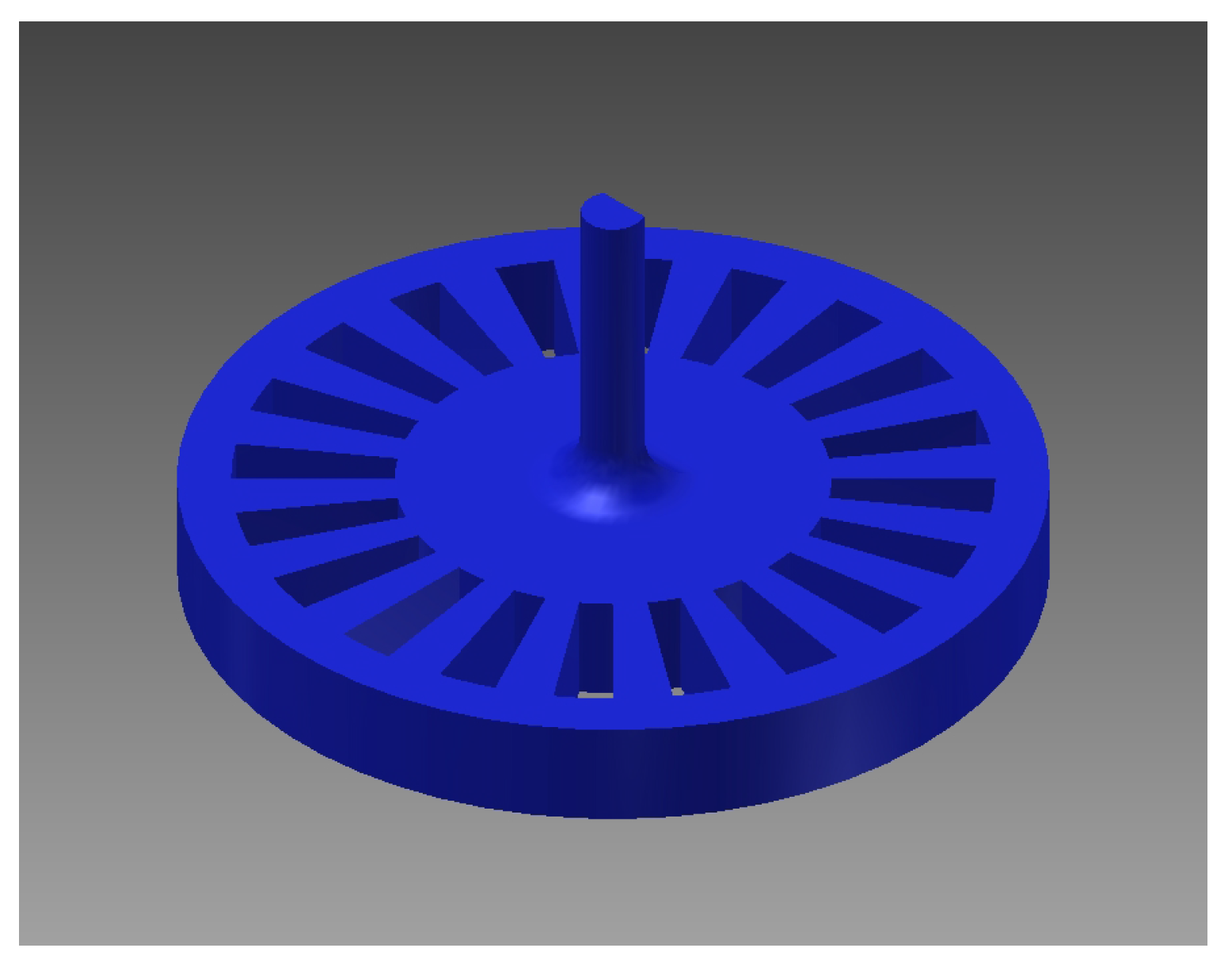
Speed Sensor
Position Sensor
Analog-to-Digital Converter
2.1.3. Simulink
Reading the Potentiometer Voltage through ADC and SPI Interface
- wiringPi.h
- wiringPi.c
- mcp3002.h
- mcp3002.c
- piHiPri.c
- wiringPiSPI.c
- mypi=raspi(’ipaddress’,’pi’,’raspberry’)
- mypi.enableSPI
Encoder to Tachometer Reading
Interface between a Computer and the Raspberry Pi
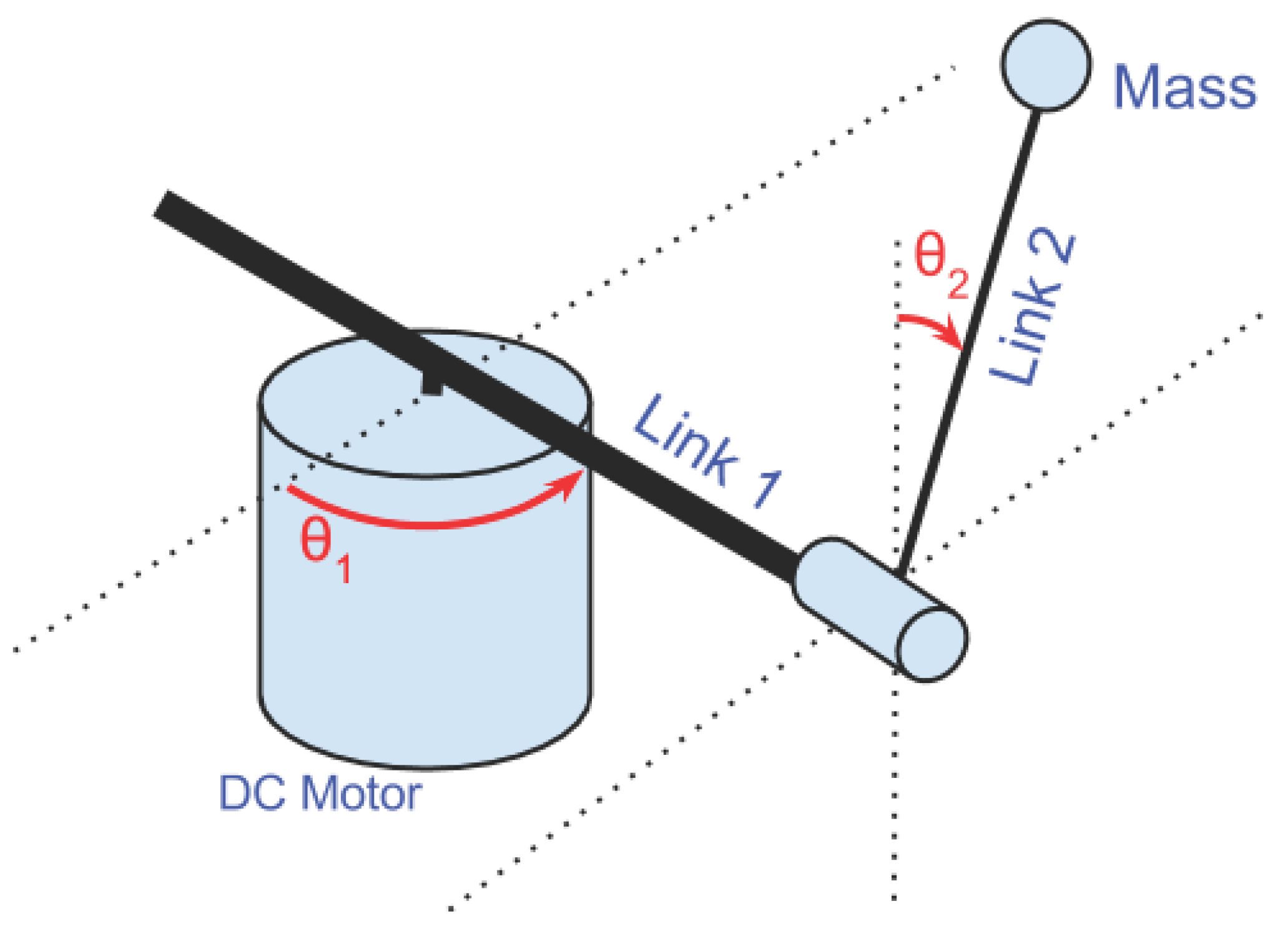
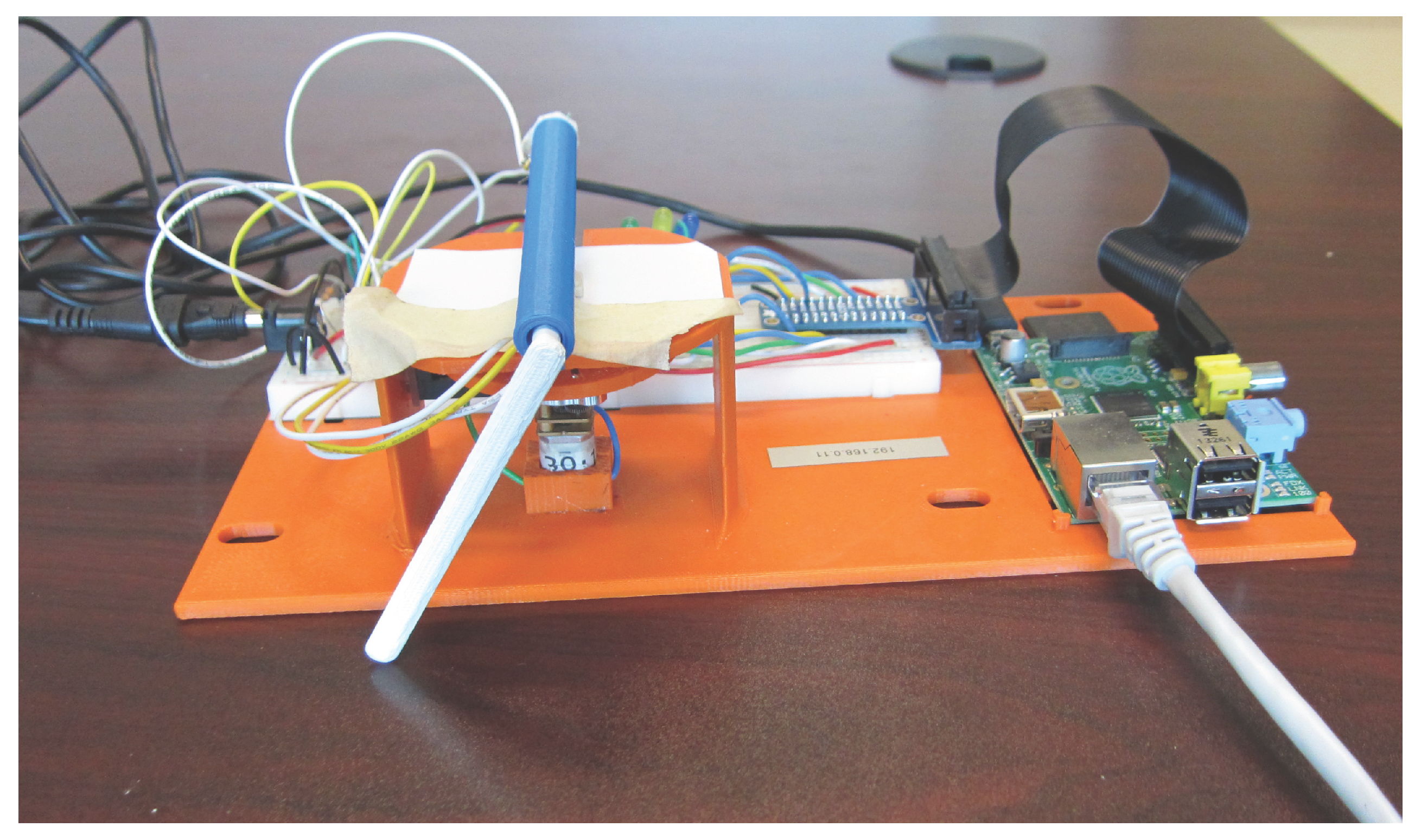
2.2. Furuta Inverted Pendulum Kit Development
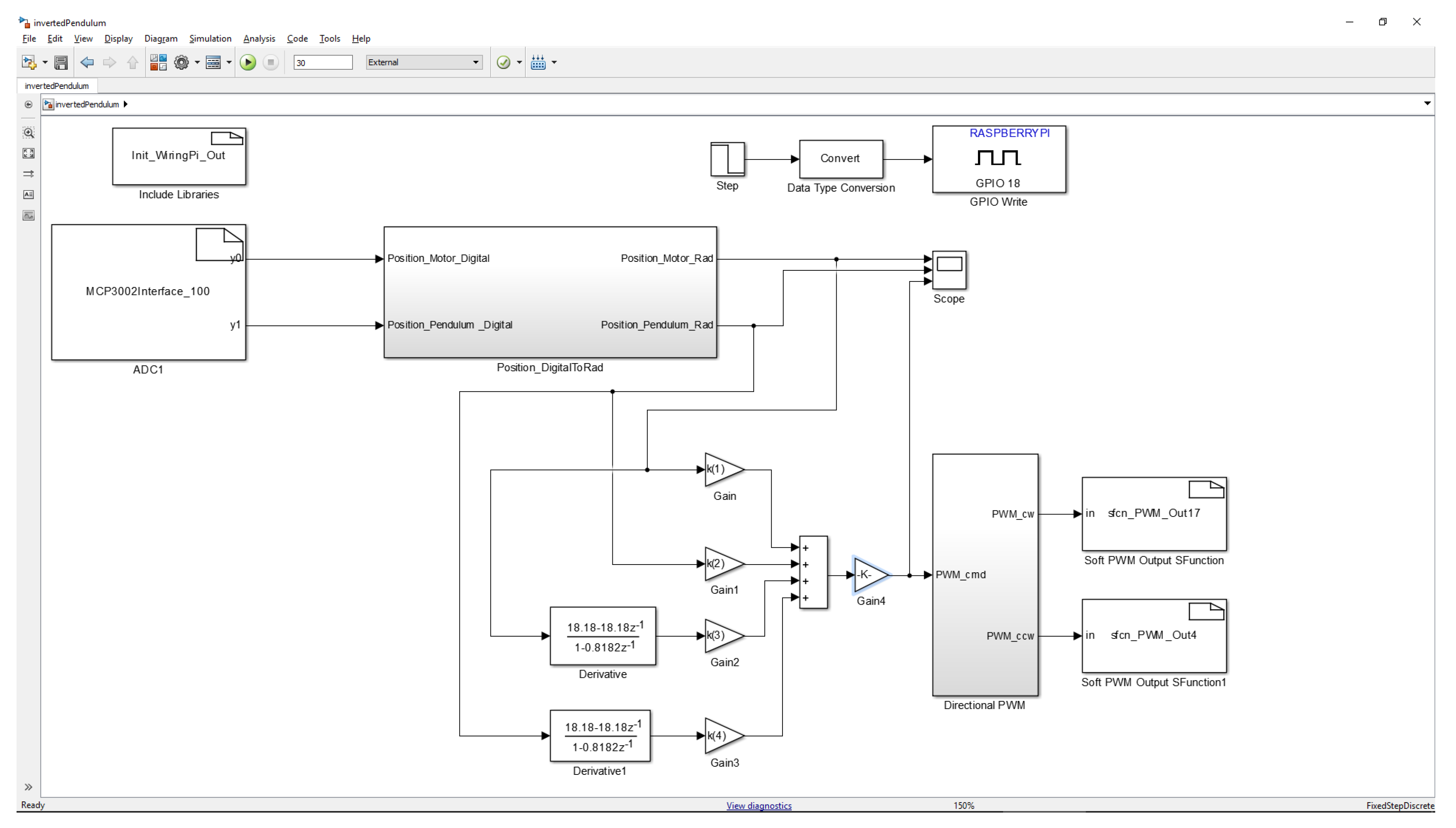
Simulink
3. Results
3.1. GE 320
3.2. GE 420
4. Discussion
5. Conclusions
Acknowledgments
Author Contributions
Conflicts of Interest
Abbreviations
| ADC | Analog to Digital Converter |
| DC | Direct Current DSP: Digital Signal Processor |
| FTP | Transfer Protocol |
| GE | General Engineering |
| GPIO | General Purpose Input/Output I2C: Inter-integrated Circuit |
| SPI | Serial Peripheral Interface |
| PID | Proportional-Integral-Derivative |
| UDP | User Datagram Protocol |
References
- Leva, A. A hands-on experimental laboratory for undergraduate courses in automatic control. IEEE Trans. Educ. 2003, 46, 263–272. [Google Scholar] [CrossRef]
- Connor, K.A.; Ferri, B.; Meehan, K. Models of mobile hands-on STEM education. In Proceedings of the 2013 American Society for Engineering Education Annual Conference and Exposition, Atlanta, GA, USA, 23–26 June 2013.
- Millard, D.; Chouikha, M.; Berry, F. Improving student intuition via Rensselaer’s new mobile studio pedagogy. In Proceedings of the 114th Annual ASEE Conference and Exposition, Honolulu, HI, USA, 24–27 June 2007.
- Aktan, B.; Bohus, C.A.; Crowl, L.A.; Shor, M.H. Distance learning applied to control engineering laboratories. IEEE Trans. Educ. 1996, 39, 320–326. [Google Scholar] [CrossRef]
- Dixon, W.E.; Dawson, D.M.; Costic, B.T.; Queiroz, M.S.D. A MATLAB-based control systems laboratory experience for undergraduate students: Toward standardization and shared resources. IEEE Trans. Educ. 2002, 45, 218–226. [Google Scholar] [CrossRef]
- Gunasekaran, M.; Potluri, R. Low-Cost Undergraduate Control Systems Experiments Using Microcontroller-Based Control of a DC Motor. IEEE Trans. Educ. 2012, 55, 508–516. [Google Scholar] [CrossRef]
- Feisel, L.D.; Rosa, A.J. The role of the laboratory in undergraduate engineering education. J. Eng. Educ. 2005, 94, 121–130. [Google Scholar] [CrossRef]
- Borgstrom, P.H.; Kaiser, W.J.; Chung, G.; Nelson, Z.; Paul, M.; Stoytchev, S.M.; Ding, J.T.K. Science and engineering active learning (SEAL) system: A novel approach to controls laboratories. In Proceedings of the 119th ASEE Annual Conference and Exposition; 2012. [Google Scholar]
- Khan, F.; Birchfield, N.; Singh, K.V. Revitalizing the engineering curriculum through studio based instruction. In Proceedings of the ASME 2012 International Mechanical Engineering Congress and Exposition, Houston, TX, USA, 9–15 November 2012; Volume 5.
- Ionescu, C.M.; Fabregas, E.; Cristescu, S.M.; Dormido, S.; Keyser, R.D. A Remote Laboratory as an Innovative Educational Tool for Practicing Control Engineering Concepts. IEEE Trans. Educ. 2013, 56, 436–442. [Google Scholar] [CrossRef]
- Boubaker, O. The inverted pendulum: A fundamental benchmark in control theory and robotics. In Proceedings of the 2012 International Conference on Education and e-Learning Innovations (ICEELI), Sousse, Tunisia, 1–3 July 2012; pp. 1–6.
- Hyder, A.C.; Thames, J.L.; Schaefer, D. Enhancing mechanical engineering distance education through IT-enabled remote laboratories. In Proceedings of the ASME 2009 International Design Engineering Technical Conferences and Computers and Information in Engineering Conference, San Diego, CA, USA, 30 August–2 September 2009.
- Stark, B.; Li, Z.; Smith, B.; Chen, Y. Take-Home Mechatronics Control Labs: A Low-Cost Personal Solution and Educational Assessment. In Proceedings of the ASME 2013 International Design Engineering Technical Conferences and Computers and Information in Engineering Conference ASME, Portland, OR, USA, 4–7 August 2013; Volume 4.
- Egbert, R. New electrical engineering laboratory facility combines traditional laboratory experiments, computer-based lab exercises, and labs taught via distance. In Proceedings of the 2009 Annual Conference & Exposition, Austin, TX, USA, 14–17 June 2009.
- Sarik, J.; Kymissis, I. Lab kits using the Arduino prototyping platform. In Proceedings of the 2010 Frontiers in Education Conference (FIE), Washington, DC, USA, 27–30 October 2010; pp. T3C:1–T3C:5.
- Sanchez, J.; Dormido, S.; Pastor, R.; Morilla, F. A Java/Matlab-based environment for remote control system laboratories: Illustrated with an inverted pendulum. IEEE Trans. Educ. 2004, 47, 321–329. [Google Scholar] [CrossRef]
- Cruz-Martin, A.; Fernandez-Madrigal, J.; Galindo, C.; Gonzalez-Jimenez, J.; Stockmans-Daou, C.; Blanco-Claraco, J. A LEGO Mindstorms NXT Approach for Teaching at Data Acquisition, Control Systems Engineering and Real-Time Systems Undergraduate Courses. Comp. Educ. 2012, 59, 974–988. [Google Scholar]
- Kim, Y. Control Systems Lab Using a LEGO Mindstorms NXT Motor System. IEEE Trans. Educ. 2011, 54, 452–461. [Google Scholar] [CrossRef]
- Studica. Available online: http://www.studica.com/mydaq (accessed on 26 September 2014).
- Maxon motor. Available online: http://www.maxonmotorusa.com/maxon/view/catalog/ (accessed on 13 March 2015).
- Nickerson, J.V.; Corter, J.E.; Esche, S.K.; Chassapis, C. A Model for Evaluating the Effectiveness of Remote Engineering Laboratories and Simulations in Education. Comp. Educ. 2007, 49, 708–725. [Google Scholar]
- Kelly, R.; Moreno, J. Learning PID structures in an introductory course of automatic control. IEEE Trans. Educ. 2001, 44, 373–376. [Google Scholar] [CrossRef]
- Henderson, G. Available online: http://wiringpi.com (accessed on 26 September 2014).
- Mathworks. Available online: http://www.mathworks.com/hardware-support/raspberry-pi-simulink.html (accessed on 29 July 2014).
- Reck, R.M. BYOE: Affordable and portable laboratory kit for controls courses. In Proceedings of the ASEE Annual Conference and Exposition, Seattle, WA, USA, 14–17 June 2015.
- Reck, R.M.; Sreenivas, R.S.; Loui, M.C. Assessing an affordable and portable laboratory kit in an undergraduate control systems course. In Proceedings of the 2015 IEEE Frontiers in Education Conference (FIE), El Paso, TX, USA, 21–24 October 2015; pp. 1–4.
- Sample Availability: MATLAB, Simulink, and 3D Model files are available from the authors.


| Item | Supplier | Cost | |
|---|---|---|---|
| Raspberry Pi Model B | Adafruit | $ | 39.95 |
| 12V DC motor | Sparkfun | $ | 12.95 |
| 3D printed stand | in house | $ | 5.00 |
| Bread board | Adafruit | $ | 5.95 |
| H bridge (L293D) | Adafruit | $ | 2.50 |
| ADC (MCP3002) | Sparkfun | $ | 2.30 |
| Power supply (for RPi) | Adafruit | $ | 9.90 |
| Power supply (for DC Motor) | Adafruit | $ | 14.95 |
| Rotary Position Sensor (3382) | DigiKey | $ | 2.60 |
| Photo Interrupter | Sparkfun | $ | 3.45 |
| Pi T-cobbler breakout & cable | Sparkfun | $ | 6.95 |
| Wires | Adafruit | $ | 1.60 |
| Resistors | ECE Store | $ | 0.15 |
| LEDs | Sparkfun | $ | 0.59 |
| SD Card | Amazon | $ | 17.09 |
| Total | $ | 125.93 |
| Exp. | Before | After |
|---|---|---|
| 1 | Introduction to GP-6 Analog Computer | Introduction to Simulink and Raspberry Pi Interface |
| 2 | Motor and sensor characteristics | Motor and sensor characteristics |
| 3 | Motor identification via physical and electrical characteristics | Functionality not available within the cost of the kit |
| 4 | Motor identification via step and frequency response | Motor identification via step and frequency response |
| 5 | Motor control (Proportional, Proportional + Derivative, & Proportional + Speed) | Motor control (Proportional, Proportional + Derivative, & Proportional + Integral) |
| 6 | System ID and Control of a non-linear system via the web | System ID and Control of a non-linear system via the web |
| Exp. | Before | After |
|---|---|---|
| 1 | Equipment Overview | Equipment Overview |
| 2 | Introduction to DSP programming with TI Code Composer Studio | Introduction to Raspberry Pi Programming with Simulink |
| 3 | More DSP/BIOS | More programming with Raspberry Pi |
| 4 | Introduction to the I/O Daughter Card | Introduction to Raspberry Pi GPIO through T-Cobbler interface |
| 5 | DAC and ADC Signal I/O | DAC and ADC Signal I/O |
| 6 | DC Motor Discrete Transfer Function Identification | DC Motor Discrete Transfer Function Identification |
| 7 | PI Motor Speed Control | PI Motor Speed Control |
| 8 | Positioning Control of a Motor Using PD, PID, and Hybrid Control | Positioning Control of a Motor Using PD, PID, and Hybrid Control |
| 9 | Notch Filter | Notch Filter |
| 10 | Discrete Full State Feedback Control of the Furuta Pendulum | Discrete Full State Feedback Control of the Furuta Pendulum |
| 11 | Control of the Furuta Pendulum using a Full Order Observer | Control of the Furuta Pendulum using a Full Order Observer |
© 2016 by the authors; licensee MDPI, Basel, Switzerland. This article is an open access article distributed under the terms and conditions of the Creative Commons Attribution (CC-BY) license (http://creativecommons.org/licenses/by/4.0/).
Share and Cite
Reck, R.M.; Sreenivas, R.S. Developing an Affordable and Portable Control Systems Laboratory Kit with a Raspberry Pi. Electronics 2016, 5, 36. https://doi.org/10.3390/electronics5030036
Reck RM, Sreenivas RS. Developing an Affordable and Portable Control Systems Laboratory Kit with a Raspberry Pi. Electronics. 2016; 5(3):36. https://doi.org/10.3390/electronics5030036
Chicago/Turabian StyleReck, Rebecca M., and R. S. Sreenivas. 2016. "Developing an Affordable and Portable Control Systems Laboratory Kit with a Raspberry Pi" Electronics 5, no. 3: 36. https://doi.org/10.3390/electronics5030036
APA StyleReck, R. M., & Sreenivas, R. S. (2016). Developing an Affordable and Portable Control Systems Laboratory Kit with a Raspberry Pi. Electronics, 5(3), 36. https://doi.org/10.3390/electronics5030036