Article

Lightweight Vivaldi Antenna for High-Voltage Ultra-Wideband Systems

by
John J. Pantoja
1,
Omar A. Nova Manosalva
2,*,
Hector F. Guarnizo-Mendez
3 and
Andrés Polochè Arango
2
1
Marshall Land Systems Ltd., The Airport, Newmarket Rd., Cambridge CB5 8RX, UK
2
Electronics and Mechatronics Engineering Department, Fundación Universitaria Los Libertadores, Bogotá 111221, Colombia
3
Electronics Engineering Department, Universidad El Bosque, Bogotá 111321, Colombia
*
Author to whom correspondence should be addressed.
Electronics 2026, 15(8), 1749; https://doi.org/10.3390/electronics15081749
Submission received: 27 January 2026 / Revised: 21 March 2026 / Accepted: 23 March 2026 / Published: 21 April 2026
(This article belongs to the Section Microwave and Wireless Communications)

Abstract

This article presents the design and characterization process of a lightweight Vivaldi antenna for high-voltage ultra-wideband systems. The proposed antenna consists of two radiating arms with different exponential curves on their inner and outer edges fed with an insulated-coplanar-plates transmission line. Weight reduction is achieved by implementing the antenna with sheets composed of a polyester layer between two aluminum layers, with a polylactic acid insulator inserted between the arms. The reflection coefficient of the implemented antenna demonstrates an impedance bandwidth ranging from 0.61 GHz to 3.44 GHz. High-voltage operation of up to 12.4 kV is also experimentally demonstrated. In addition to satisfying the high-voltage and ultra-wideband operational requirements, the proposed antenna is shown to achieve, among antennas with comparable characteristics, the most effective combination of low minimum operating frequency and low weight. The transfer function between the voltage applied to the antenna, V s , and the radiated electric field, E r , is measured. Using this transfer function, the radiated electric field is calculated for an input voltage pulse with a rise time of 110 ps to confirm the antenna’s capability of producing radiated pulses with low distortion. The calculated radiated electric field pulse closely matches the results obtained with full-wave simulation. To assess the similarity between the radiated and applied pulses, the pulse width stretch ratio is calculated, yielding a variation of 3.86% for the direction of maximum gain and 9.36% for 30° in the H-plane of the antenna. This feature is desirable for EMC, EMI and sensing applications. The antenna is also characterized in the frequency domain, achieving a maximum gain of 10.09 dBi at 3.63 GHz and a 30° 3 dB beamwidth for ultra-wideband pulses.

1. Introduction

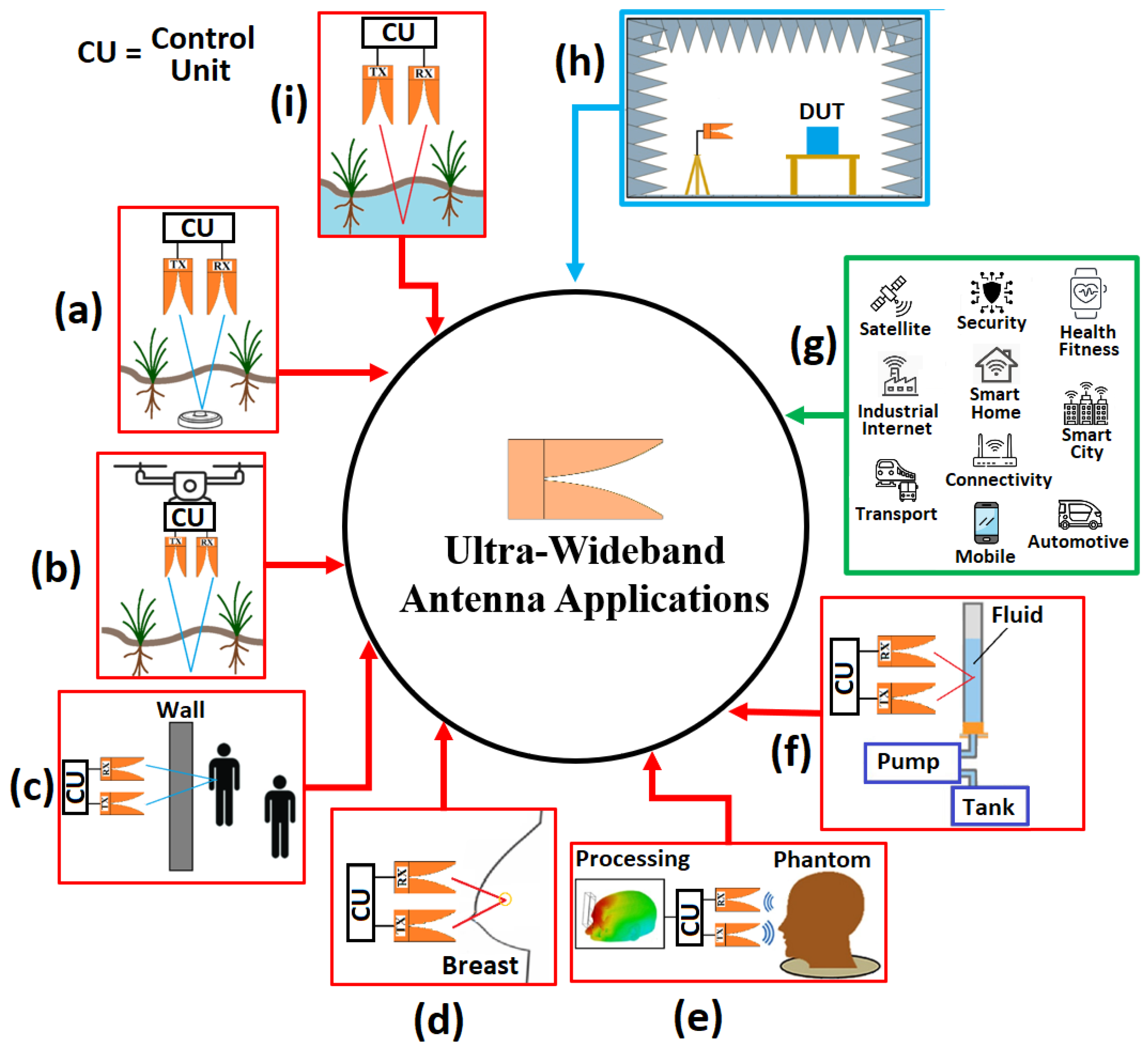
Ultra-wideband (UWB) antennas are key enabling components of modern wireless technologies that require high speed [1], high bandwidth [2], diversity [3,4], and low signal distortion [5]. Applications range from high-speed data transmission [6], water detection [7], and landmine detection [8] to biomedical imaging [9,10], radar [11], through-wall radar (TWR) [12], fluid properties determination [13], and intentional electromagnetic interference [14], as shown in Figure 1. One of the most widely used antennas for UWB applications is the Vivaldi antenna, a type of tapered slot antenna (TSA). Originally called Vivaldi aerial [15], the Vivaldi antenna is characterized by its high gain, wide bandwidth, low cross-polarization level, and stable radiation characteristics. Various optimization techniques have been proposed to enhance its performance, including feeding mechanisms, slot integration, radiator shape modifications, inclusion of dielectric lenses, parasitic patches between the two radiator arms, edge corrugations on the arms, and the use of metamaterials [16].
Vivaldi antennas are commonly used in ground-penetrating radar (GPR) due to the characteristics mentioned above and also due to their compactness [17]. GPR antennas must meet the following conditions: they must be broadband, have narrow beam-width radiation patterns, and be capable of radiating medium-power pulses. In the case of bi-static GPR, low crosstalk is also required. Crosstalk can be reduced by using arrays with directive antennas, such as Vivaldi [18,19] and shielded bowtie [20] antennas. Moreover, it is necessary to consider the near-field interaction with the soil and the target, which affects crosstalk, impedance matching, and detection efficiency. Stadler et al. [21] show that the full-wave simulation approach, including the antenna model, is required to accurately determine the near-field antenna coupling with the soil, which has frequency-dependent permittivity in the GPR operational frequency range [22].
To achieve broadband performance, geometries such as the hybrid antenna presented in [23] can be used. This design combines two modes of operation: a broadband monopole mode between 200 MHz and 400 MHz and a Vivaldi antenna mode between 400 MHz and 20 GHz. In this case, the radiation pattern is not critical, as the antenna is designed to be used in a reverberation chamber (RC), where mode stirrers generate an isotropic average antenna pattern.
UWB antennas are also used to characterize radiated pulsed emanations of secure communications systems [24]. Typical spectral content of radiated signals from components used in quantum communications, for instance, ranges from 40 MHz to 1 GHz [25]. UWB directive antennas, such as double-ridge guide horn, are preferred for electromagnetic (EM) emission measurements. However, to achieve low frequency operation, size and weight scale up result in large (i.e., squared meter aperture or cross-section) and heavy (i.e., tens of kg) antennas [26].
UWB antennas for electromagnetic compatibility (EMC) tests must have stable characteristics with frequency. In ref. [27], the characterization of a printed-circuit-board Vivaldi antenna for electromagnetic field measurements in EMC tests is presented. An operation frequency range between 0.5 GHz and 4 GHz with an impedance mismatch around 1.5 GHz is reported. This antenna is a low-cost alternative compared to other options covering the same frequency range and is proposed as a replacement for multiple narrowband antennas traditionally used in shielding effectiveness testing. The antenna is fed using a coaxial cable; however, the design does not incorporate any balun to provide the balanced signals required by the Vivaldi antenna.
Directive antennas are preferred for radiated immunity and intentional electromagnetic interference (IEMI) testing. These tests require compliance with field uniformity criteria on surfaces where the devices under test (DUT) are located. A hyperband antenna for IEMI applications is presented in [28]. In addition to achieving the field uniformity criterion, this antenna achieves the radiation of high-power pulses with amplitudes on the order of 6 kV. The bandwidth of this antenna is also wide, as it can radiate pulses with a rise time on the order of 90 ps. Recently, tests have been reported on this antenna with source voltages up to 24 kV [29].
One option to achieve radiation patterns with high gain and beam-steering capability is through the use of antenna arrays. An example of such an array, with broadband operation, is presented in [30]. This array is capable of radiating high power for use in high-power jamming systems. To prevent arc flashes when handling high power, the antenna tips are rounded to reduce the electric field intensity around them. Additionally, the array is constructed entirely of metal, as antennas manufactured on substrates tend to have low durability when operated at high power. An 8x8 array with a ±45° slant configuration operates between 2 GHz and 6 GHz, achieving gains between 18 dBi and 21 dBi for various beam-steering angles.
In ref. [31], a linear 1 × 10 array of antipodal Vivaldi antennas is presented, where the effect of adding metallic inserts to the metallizations and slots of each element is explored. The best performance is observed when two inserts are added to the slots, resulting in an operating frequency range from 5.7 GHz to 12.0 GHz, a gain between 12 dBi and 19 dBi within this range, and a radiated power between 0.75 W and 0.9 W.
In ref. [32], a compact Vivaldi antenna array for UWB pulse radiation is proposed. To compact the array, the ends of the radiating elements are bent in both directions. To expand the impedance bandwidth, short-circuited branches are inserted between the bent radiating elements and the ground plane. This design results in an 8 × 4 array capable of radiating UWB pulses with an impedance bandwidth ranging from 1.4 GHz to 6 GHz and a compact size of 2.5 cm × 2.5 cm × 4.5 cm. The gain varies between 7.5 dBi and 20 dBi.
Antennas capable of radiating pulses must be analyzed not only in the frequency domain but also in the time domain. While parameters such as gain, reflection coefficient, and group delay as a function of frequency are important, they are insufficient for this type of antenna. It is necessary to characterize the distortion introduced by the antenna on the transmitted pulses [33]. This time-domain characterization includes parameters such as pulse width stretch ratio (SR) to establish the similarity between the transmitted and received pulses [34].
A common application of antennas capable of radiating high-power pulses is through-wall radar and imaging of nearby objects. For through-wall radar (TWR), antennas with high gain, wide bandwidth, and effective wall penetration capabilities are required. These features are provided by the Vivaldi antenna, which also exhibits directional radiation patterns that enhance wall penetration. In ref. [35], structural optimizations, feeding techniques, and performance improvement strategies for Vivaldi antennas are presented to enhance their imaging and detection capabilities for through-wall radar applications.
For imaging nearby objects, ref. [36] describes the design of an antipodal Vivaldi antenna (AVA) capable of radiating impulse-type waveforms. The antenna operates between 1.8 GHz and 10 GHz, and its design focuses on optimizing its pulse response in the time domain. This involves analyzing the transfer function between two identical antennas, the shape of the received pulse, group delay, and gain. The antenna successfully reconstructs two radar targets positioned 7 cm apart.
Recent advances in Vivaldi antennas have focused on enhancing both the frequency- and time-domain performance of these antennas through optimization techniques, structural modifications, and array-oriented designs. For instance, the integration of metamaterial-inspired features and advanced hybrid optimization algorithms has been shown to significantly improve gain, bandwidth, and radiation efficiency while maintaining high fidelity in UWB operation [37,38]. In parallel, array-oriented approaches incorporating composite decoupling structures and spoof surface plasmon polariton (SSPP)-based techniques have demonstrated substantial improvements in isolation between antenna elements, effectively mitigating mutual coupling while preserving radiation characteristics and enabling gain enhancement through metasurface-based phase compensation [39,40]. Moreover, resistive loading strategies in dual-plane Vivaldi configurations have been reported to suppress time-domain reflections and enhance power-handling capability while preserving radiation performance, which is critical for short-pulse high-voltage applications [41]. Complementarily, systematic methodologies for controlling, guiding, and absorbing residual electromagnetic energy within Vivaldi structures—through the use of multiple slots, distributed resistors, and inhomogeneous metamaterials—have been shown to further improve radiation efficiency and overall antenna performance [42]. Additional studies have explored compactness, gain enhancement, and functional versatility in Vivaldi antennas. Miniaturization techniques based on nonuniform slot profiles and dielectric loading enable reduced size while preserving gain [43]. Other works address low radar cross-section designs and extremely wide bandwidths [44], as well as array configurations for improved directivity in sensing applications [45]. Furthermore, polarization reconfigurable arrays and corrugated structures with notched-band and rectenna integration expand operational flexibility and application scope [46,47].
Despite these advances [37,38,39,40,41,42,43,44,45,46,47], the design of Vivaldi antennas for high-voltage UWB systems still presents significant challenges, including dielectric breakdown prevention, insulation requirements, and the need to preserve pulse integrity under high electric field excitation. Furthermore, practical implementations increasingly demand lightweight structures without compromising electromagnetic performance, especially in portable or field-deployed systems. While prior works have addressed bandwidth enhancement, gain optimization, mutual coupling reduction, reflection suppression, and internal energy management, the combined achievement of low operating frequency, reduced weight, and high-voltage capability remains a relatively underexplored area. In this context, the development of lightweight Vivaldi antennas capable of handling high-voltage excitation while preserving ultra-wideband performance and low pulse distortion constitutes a critical research direction.
As a summary of the main characteristics of several UWB antennas used in EMC, IEMI, and radar applications, Table 1 is presented. One of the main advantages of the antenna proposed in this article is its ability to achieve a low operating frequency, referred to herein as the minimum frequency, f m i n , while maintaining a low weight, w. To highlight the effectiveness of the antenna in simultaneously minimizing these two parameters, a metric defined as the product of f m i n and w was introduced. The value achieved by the proposed design is compared with those of other representative UWB and high-voltage antennas in Table 2. As observed, the proposed design yields the lowest value of this metric among all of the considered antennas.
This paper is organized as follows. Section II outlines the antenna design to achieve the desired impedance matching. Section III describes the procedure for implementing and testing the antenna, presenting the obtained reflection coefficient and the radiated electric field. Section IV details the characterization of the designed antenna in the time domain, presenting an analysis of the waveform responses and calculating the pulse width stretch ratio (SR) for different pulses over the main planes of the antenna.
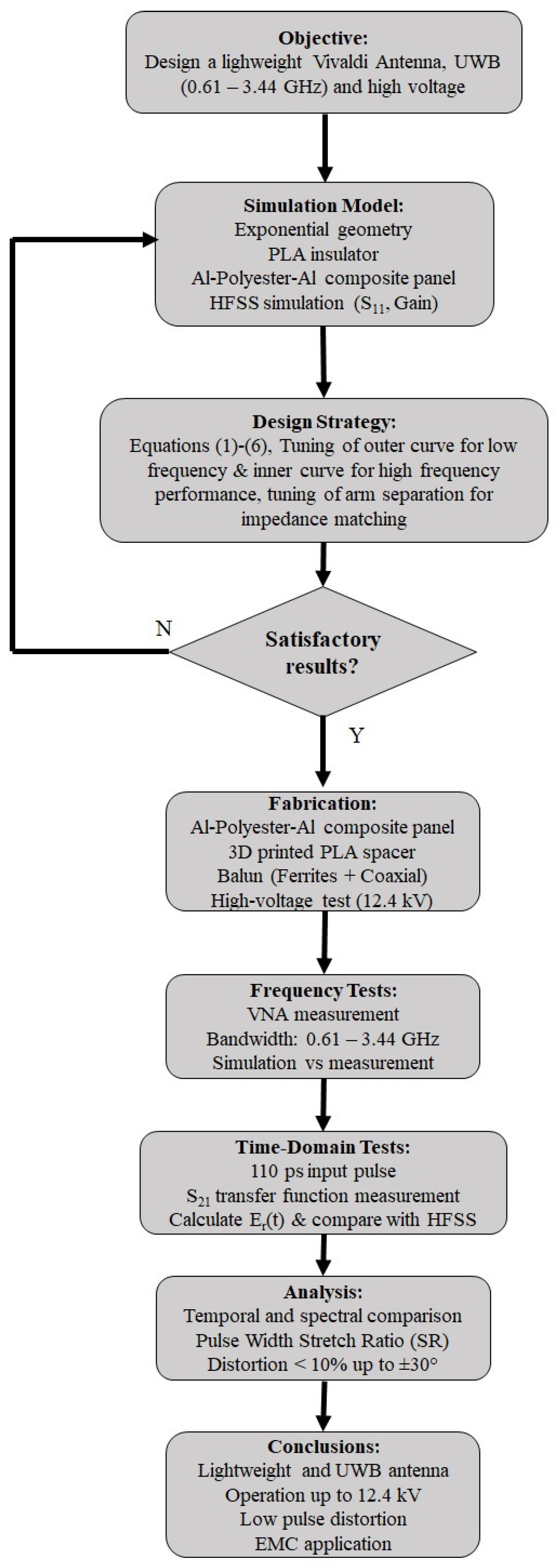
Figure 2 summarizes the workflow followed in this study: (i) geometry definition and Ansys (Canonsburg, PA, USA) HFSS (2025 R2)-based parametric design of a differential Vivaldi with exponential inner/outer tapers and a PLA spacer, using lightweight aluminum–polyester–aluminum sheets; (ii) prototype fabrication and high-voltage feed implementation with ferrite-ring and tapered-coax baluns, qualified to 12.4 kV; (iii) frequency-domain validation with a VNA showing a measured impedance bandwidth of 0.61–3.44 GHz; and (iv) time-domain assessment using a 110 ps input pulse and an S 21 -derived transfer function to compute the radiated field E r ( t ) , followed by pulse-width stretch ratio analysis. This process map clarifies how the lightweight, wideband, and high-voltage requirements were achieved and verified.


2. Antenna Design

Various design approaches have been proposed to improve the performance of Vivaldi antennas in ground-penetrating radar (GPR) applications. These include the incorporation of combined slots at the edges to extend the electrical length and achieve frequencies from 75 MHz [55], the optimization of feeding strategies such as microstrip, curved microstrip, and CPW to expand bandwidth and gain [56], the inclusion of elliptical slots in antipodal E-shaped configurations to reduce the cutoff frequency [57], and the design of S-band Vivaldi arrays optimized by parametric sweeps to improve coupling and directivity [58].
Various antenna configurations have been proposed to improve the performance of GPR systems. These include a suspended elliptical patch with an optimized slot that achieves bandwidths of 878–1260 MHz and gain >8 dBi [59]; a low-profile bowtie antenna with a loaded elliptical patch and reflector plane, which reduces the minimum frequency to 0.18 GHz and achieves compact dimensions with 7.41 dBi gain [60]; and a slotted bowtie with bent arms and absorbent backing, covering 0.5–3 GHz and offering >30 dB isolation [61].
UWB antennas such as the one designed in this article can also be used in applications that require high-capacity, low-latency and reliable communications in 5G/6G networks [62], as well as in satellite links using MIMO-UWB systems, which increase spectral efficiency and support emerging applications such as IoT and massive communications [63].
In electromagnetic compatibility tests, antennas are made to withstand high voltages through the use of multilayer lenses that adjust dielectric constants and improve directivity [64], and geometric optimization of the aperture and propagation in TEM horn antennas [65].
Three main goals are addressed in the design using tuning of several variables: (i) wide-band impedance matching by adjusting the geometry and materials through parametric simulations, (ii) light weight by using aluminum composite boards, and (iii) high voltage by isolating the differential feed point.

2.1. Geometry and Materials

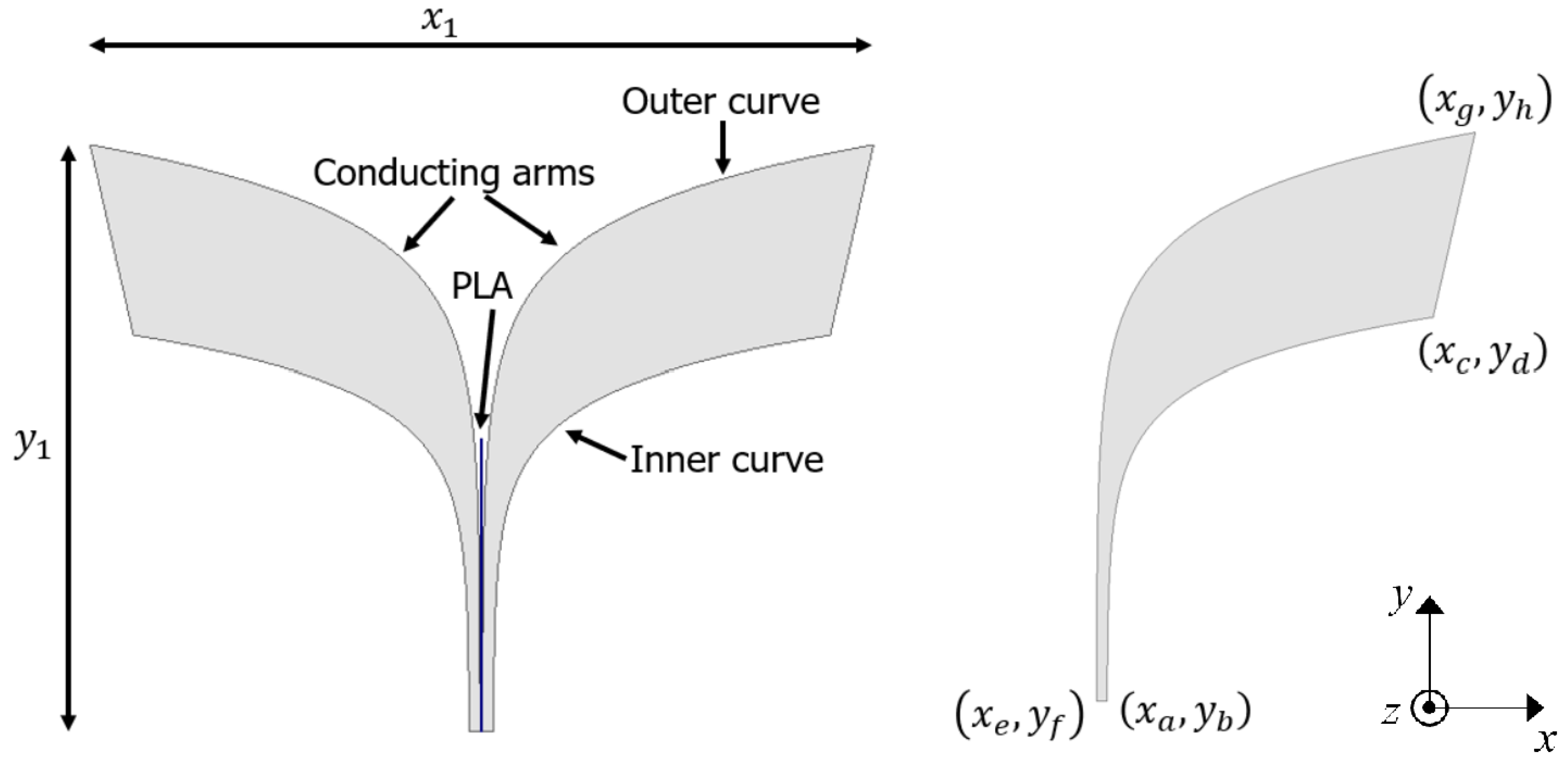
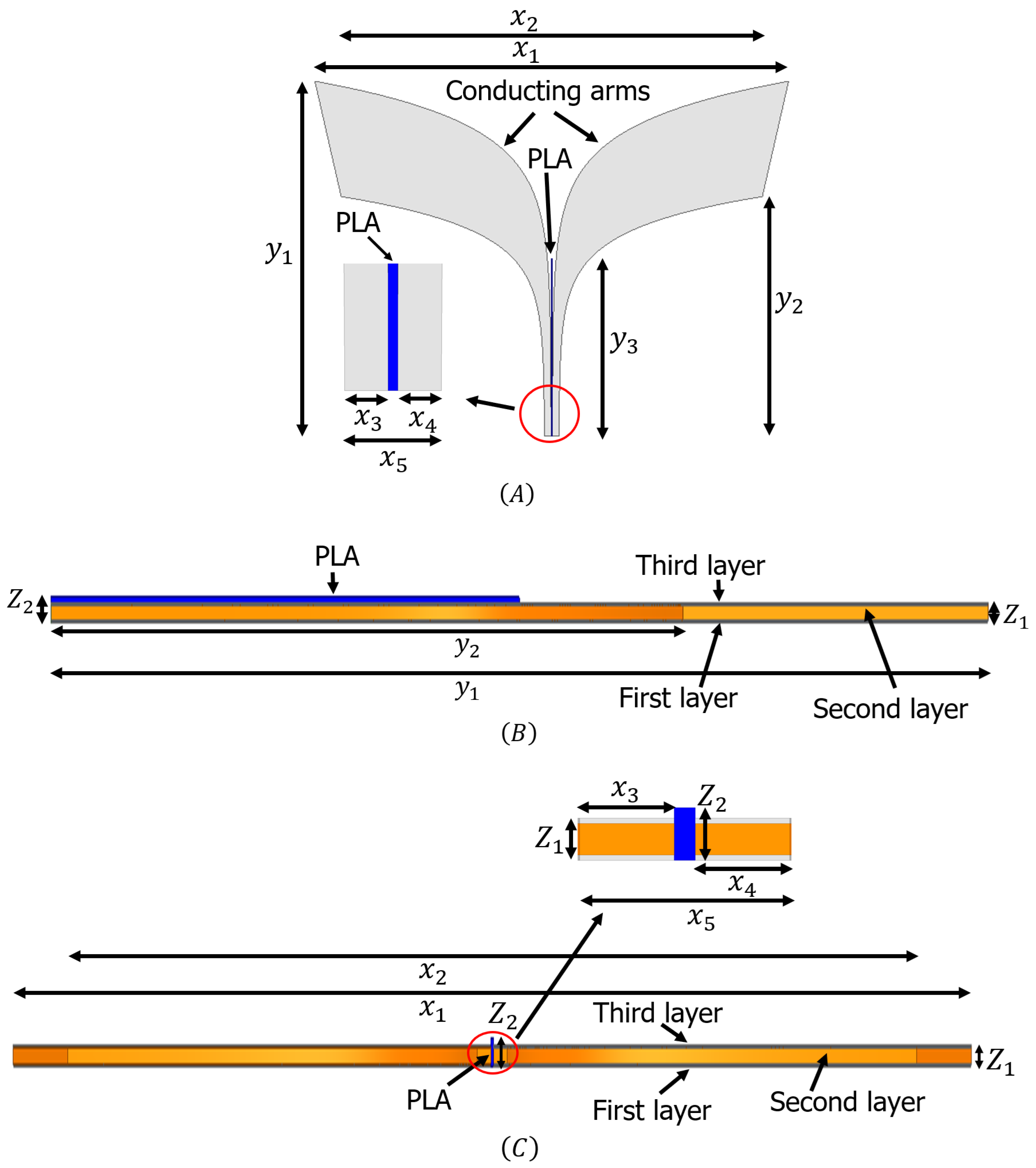
The configuration of the proposed Vivaldi antenna is shown in Figure 3. This antenna is designed from two identical conductive arms (radiating arms) with an insulator of polylactic acid (PLA) between the arms. The material of the radiating arms is aluminum. The antenna size is set at 64.2 ( x 1 ) × 48 ( y 1 ) cm2.
The inner curves of the antenna (see Figure 3) follow an exponential function described by the following:
y = F 1 e M x + F 2
where
F 1 = ( y d y b ) ( e M x c e M x a )
F 2 = ( y b e M x a y d e M x c ) ( e M x c e M x a )
The outer curves of the antenna (see Figure 3) follow an exponential function described by the following:
y D = E 1 e N x + E 2
where
E 1 = ( y h y f ) ( e N x g e N x e )
E 2 = ( y f e N x e y h e N x g ) ( e N x g e N x e )
The equations’ symbols are presented in Table 3 and Figure 3. The values of these symbols are given in Table 4.
Figure 3. Proposed Vivaldi antenna.
Electronics 15 01749 g003
Equations (1)–(6) were used to obtain an initial state for the antenna. As indicated in the flowchart shown in Figure 2, the design was carried out by tuning several variables through parametric analysis in order to achieve the desired response in both S 11 and gain. Simulations performed in Ansys HFSS targeted an S 11 below −10 dB over the frequency range from 0.61 GHz to 3.44 GHz, as well as a gain greater than 8 dBi for frequencies above 2 GHz. The parametric simulations were applied to the amplitude and rate of variation of the exponential equations governing the inner and outer contours of the antenna arms (see Equations (1)–(6)), as well as to the separation between the arms at the feed point (see Figure 4). The thickness of the aluminum–polyester–aluminum laminate used to implement the arms (variable z 1 in Figure 4) was also a critical parameter in the tuning process. Through simulation, it was determined that this thickness had to be at least 3 mm to meet the specified S 11 and gain requirements.
Table 3. Symbols for the equations of the inner and outer curves of the antenna.
SymbolRepresentation
( x a , y b ) Starting point of the inner curve
( x c , y d ) End point of the inner curve
MCurvature rate of the inner curve
( x e , y f ) Starting point of the outer curve
( x g , y h ) End point of the outer curve
NCurvature rate of the outer curve
Figure 4. Final configuration of the proposed Vivaldi antenna: (A) top view, (B) side view, and (C) front view. Different materials are represented using distinct colors: aluminum in gray, polyester in yellow, and PLA in blue.
Electronics 15 01749 g004
Table 4. Dimensions of the proposed Vivaldi antenna.
ParameterValue (mm)ParameterValue (mm)
x 1 642 z 1 3
x 2 571 z 2 6
x 3 9 y 1 480
x 4 9 y 2 324
x 5 20 y 3 240
x a 10 y b 0
x c 285 y d 324
x e 1 y f 0
x g 321 y h 480

2.2. Weight Reduction

To reduce the overall weight of the antenna, each conductive arm was replaced by a layered structure with one dielectric layer of 2 mm in between two conductive layers of 0.5 mm. That is, from bottom to top, there is a conductive layer (aluminum), then a second dielectric layer (polyester), and finally a third conductive layer (aluminum). Using aluminum composite panels provides a weight reduction of 66.7% when compared to the same-sized aluminum sheet. Figure 4 shows the final configuration of the proposed Vivaldi antenna. The simulation was conducted using Ansys HFSS, where the dimensions of the radiation box were adjusted to 14.5 × 14.5 × 14.5 cm3.
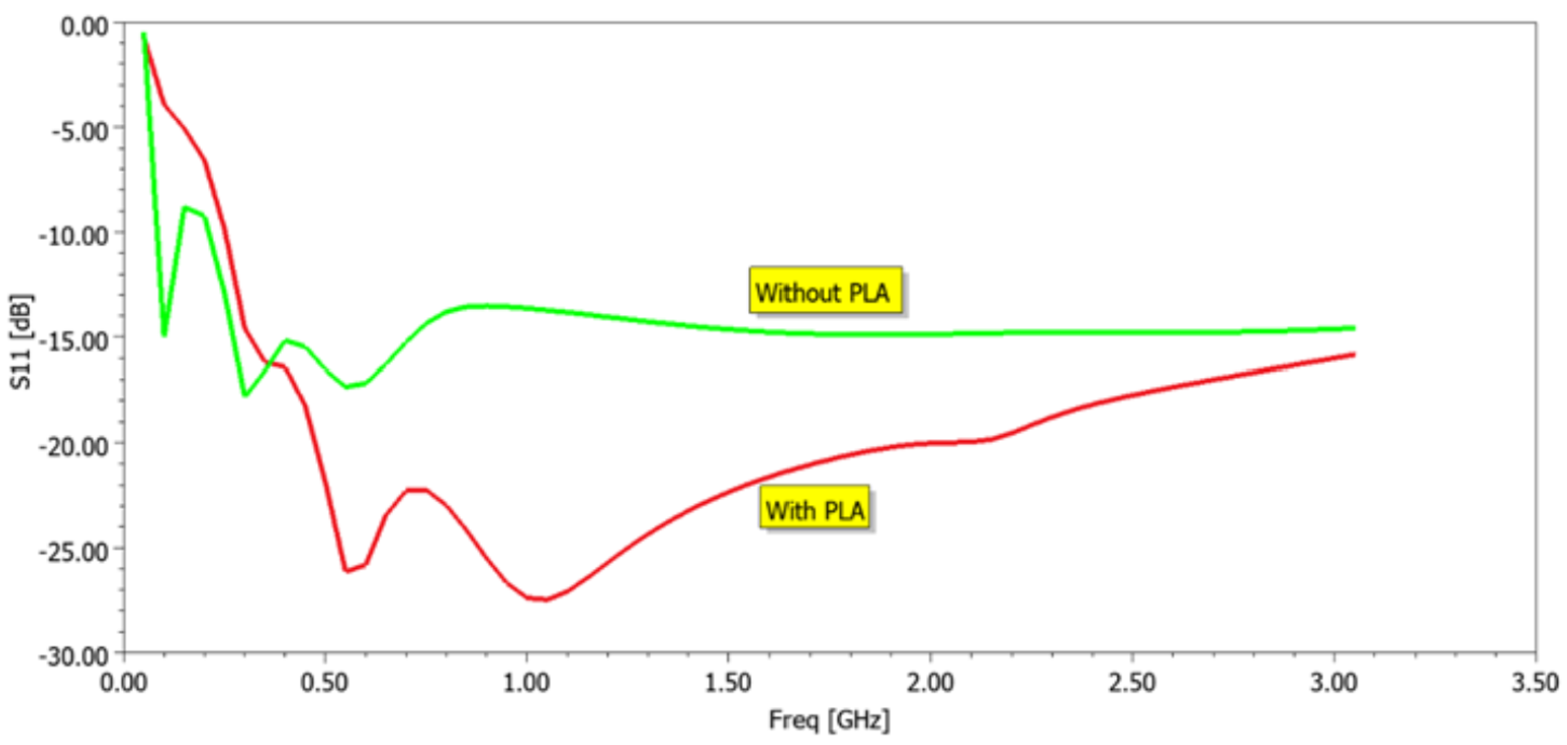
Table 4 shows the parameters and their values for the proposed antenna. Figure 5 shows the S 11 parameter of the proposed antenna with and without the insulator (i.e., PLA). It is observed that antenna matching improves with the presence of the insulator located between the conductive arms.

2.3. Feed Point

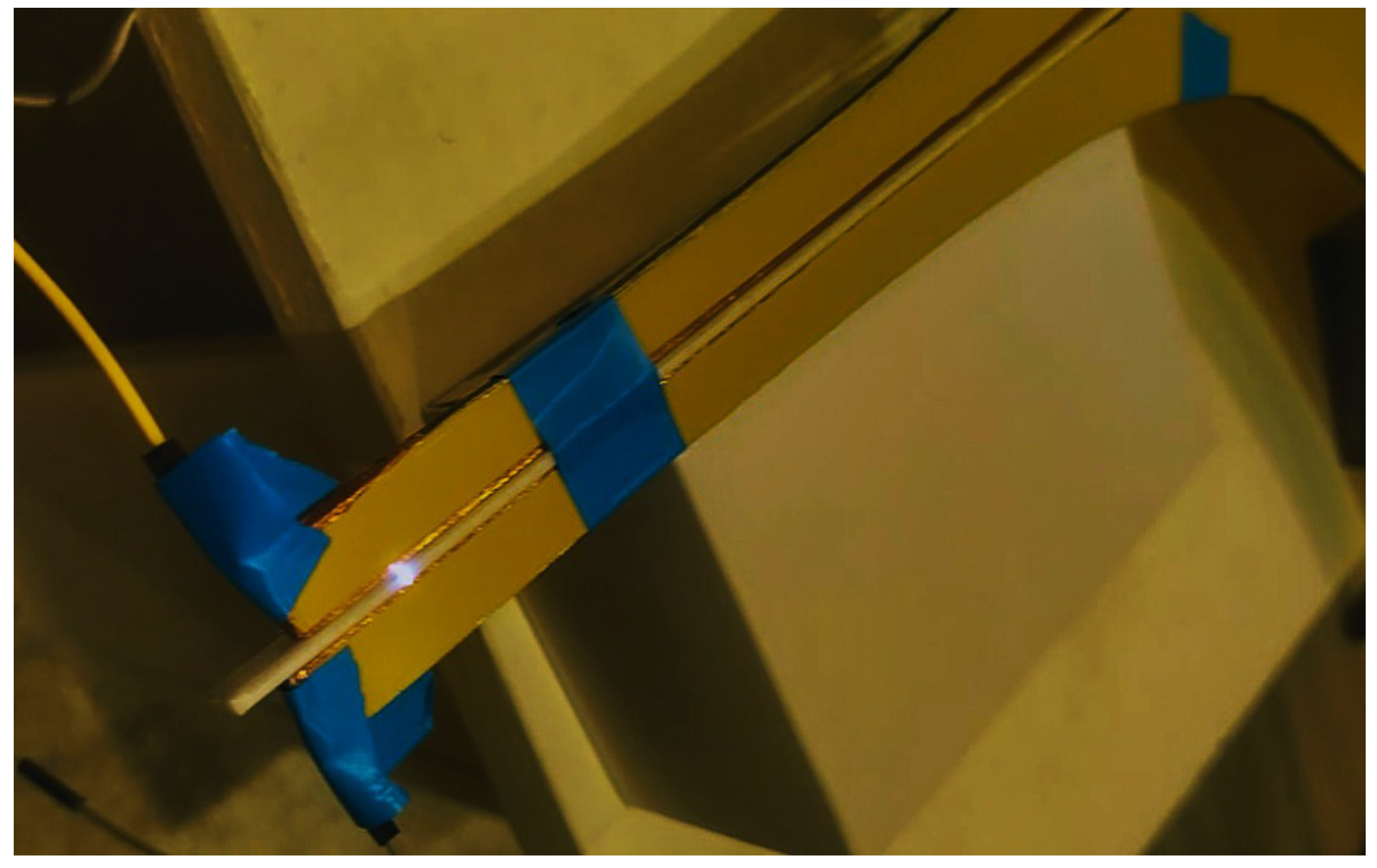
The antenna feed point was designed to handle high voltage and provide a wideband transition to a single-ended coaxial transmission line. In addition to improving the matching impedance, the PLA strip between the two arms also provides electric insulation. It was experimentally verified that the design has a breakdown voltage of 12.4 kV. Figure 6 shows a spark produced during the test when the high voltage applied at the feed point exceeds this threshold.
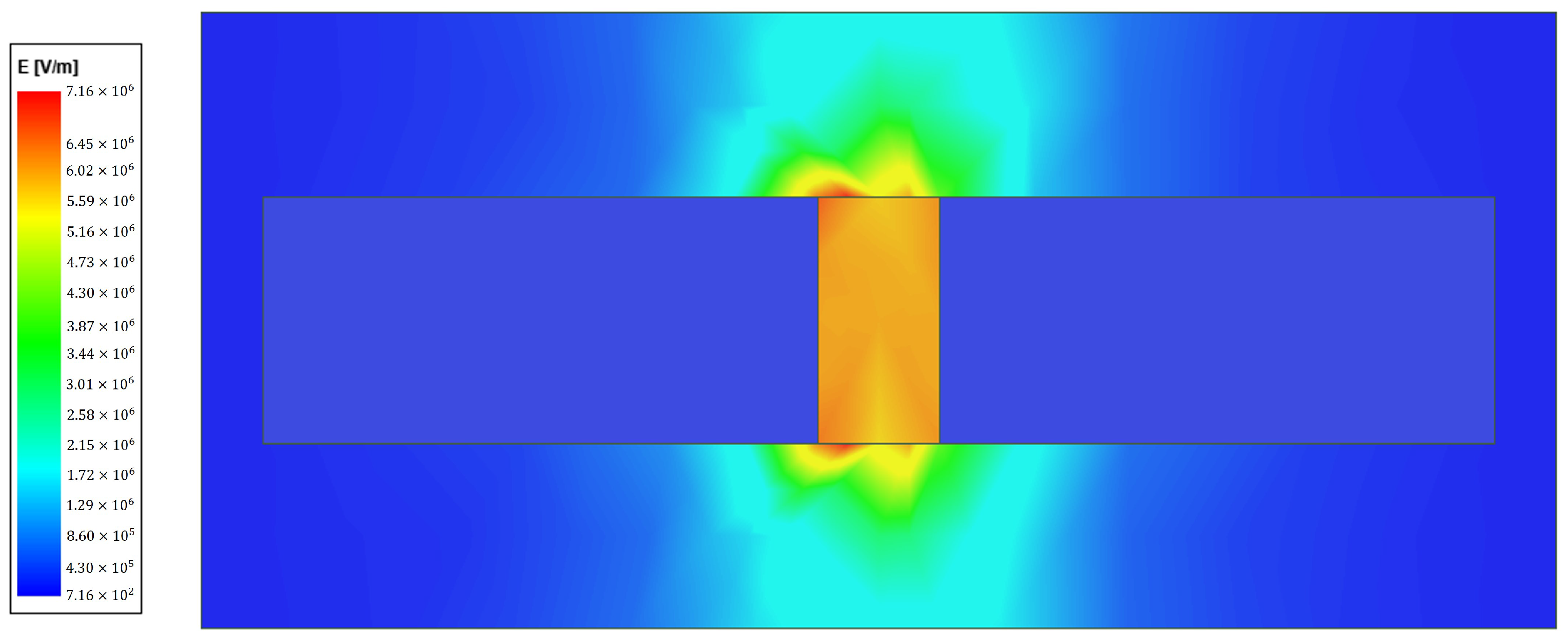
The design of the electrical insulation provided by the PLA strip was carried out through electrostatic simulations in Ansys Maxwell. Figure 7 shows the cross-sectional view of the antenna feed point when one electrode is energized at 12.4 kV and the other is connected to 0 V. The magnitude of the electric field intensity in the region surrounding the feed point is plotted, revealing that the dielectric breakdown strength of air, 3 MV/m, is exceeded at the upper and lower edges of the PLA strip connecting the two electrodes.
A balun was implemented using two ferrite rings of 4W620 material from Würth Elektronik on the differential transmission line at the feed point. This provides common-mode current rejection up to 1 GHz. To provide a smooth propagation mode transition for higher frequencies, a coaxial cable tapered 1:1 balun was implemented at the connection point by gradually removing the screen of the coaxial cable [66].
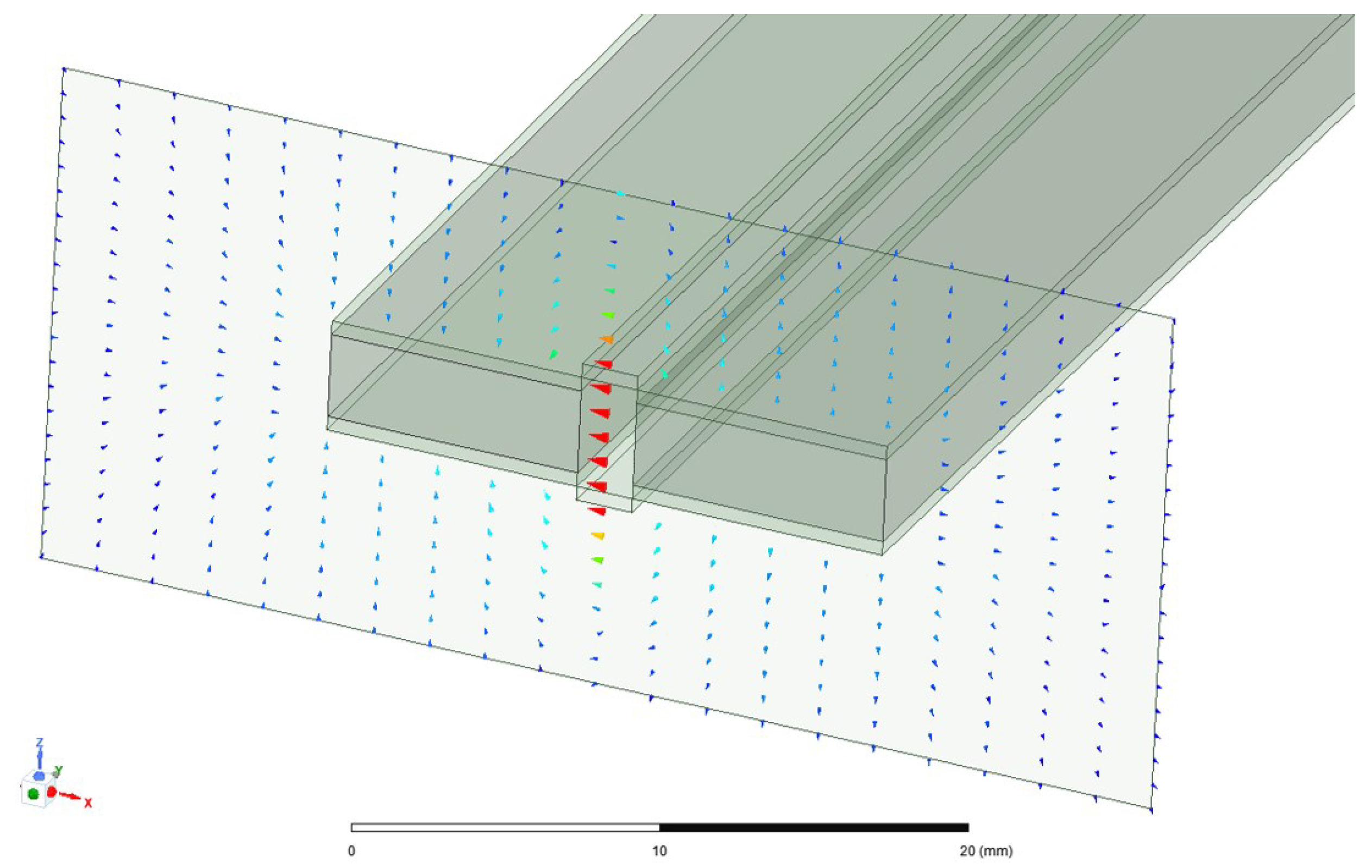
The characteristic impedance of the antenna feed line was determined through simulation in Ansys HFSS for the mode illustrated in Figure 8, yielding Z 0 = 55.02 + j 0.24 [ Ω ].
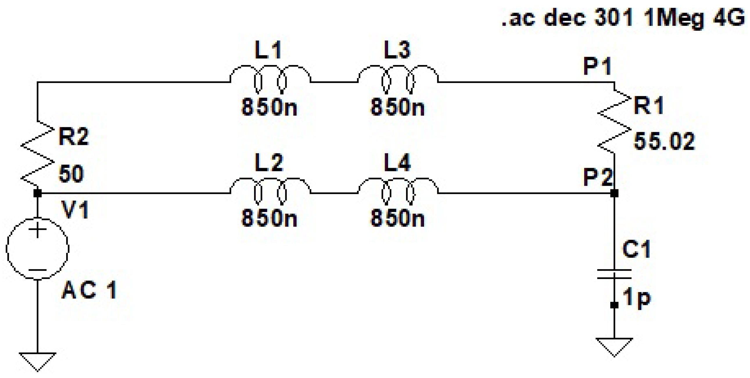
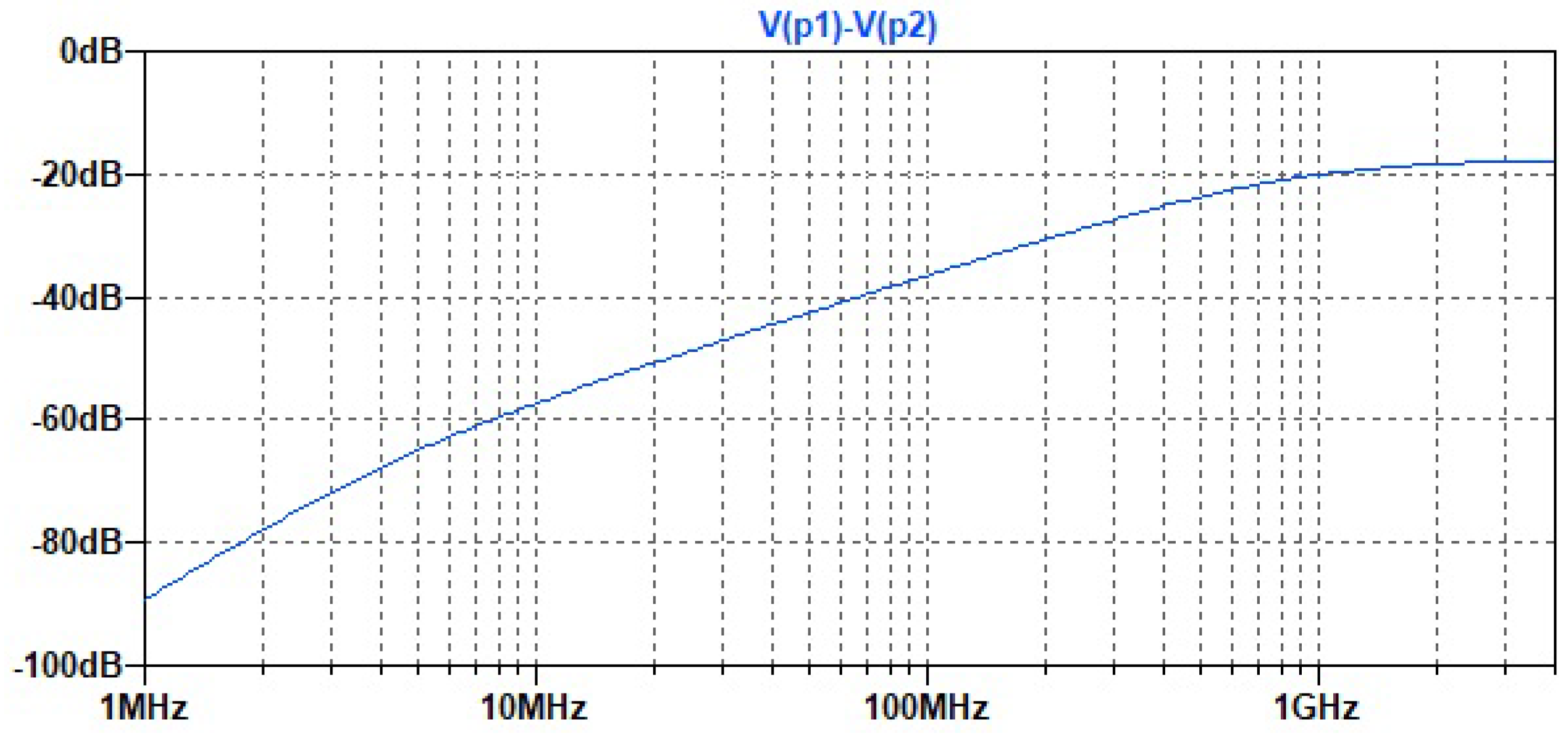
The common-mode rejection provided by the ferrite rings was simulated in LTSpice by modeling the ferrites as 850 nH inductors and assuming 1 pF parasitic capacitance, as shown in Figure 9. The ferrite model included 3.2 mOhm series resistance, 150 Ohm parallel resistance, and 50 fF parallel capacitance. A 50-Ohm differential source and load of 55.02 Ohm were considered for calculations. As shown in Figure 10, the common-mode rejection is higher than 20 dB for frequencies below 1 GHz and higher than 18 dB for frequencies below 4 GHz.
Figure 6. High-voltage test of the antenna feed point. A spark is produced around the PLA insulator at 12.4 kV.
Electronics 15 01749 g006
Figure 7. Electrostatic simulation used to design the insulation of the PLA strip.
Electronics 15 01749 g007
Figure 8. Propagation mode of the antenna feed line. The arrows indicate the direction of the electric field. Dark blue arrows represent the minimum electric field magnitude, while red arrows represent the maximum magnitude.
Electronics 15 01749 g008
Figure 9. Schematic circuit diagram used for common-mode rejection analysis.
Electronics 15 01749 g009
Figure 10. Common-mode rejection of the ferrite rings.
Electronics 15 01749 g010

2.4. Gain

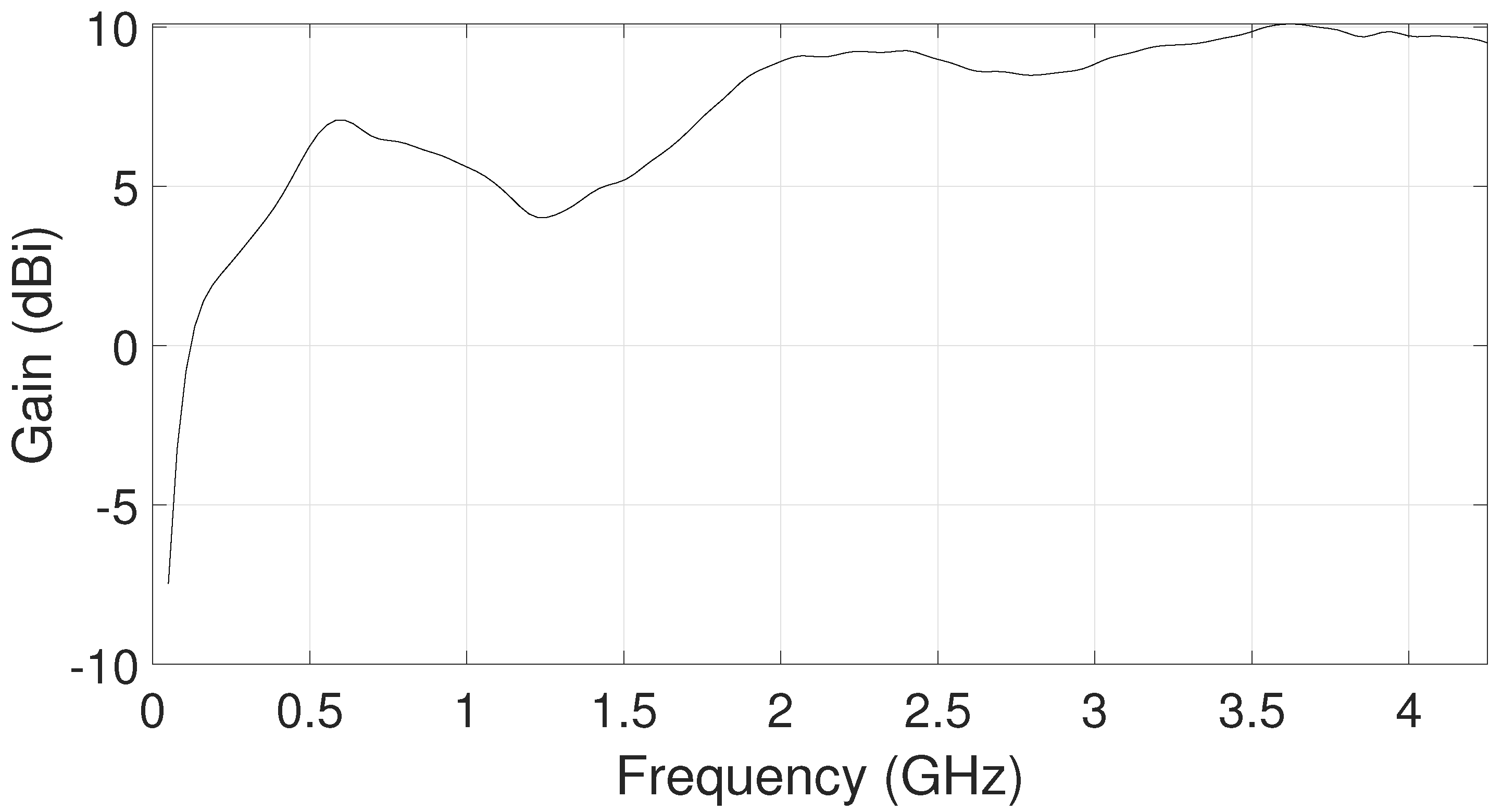
The maximum gain of the main lobe of the designed Vivaldi antenna was simulated in Ansys HFSS, with the results shown in Figure 11. The gain is plotted over the frequency range from 50 MHz to 4.25 GHz. The gain, expressed in dBi, is positive for frequencies above 134 MHz and varies from a minimum value of 0.60 dBi at 134 MHz to a maximum value of 10.09 dBi at 3.63 GHz. Above 1.87 GHz, the gain consistently remains within the range of 8.24 dBi to 10.09 dBi.

2.5. Radiation Efficiency

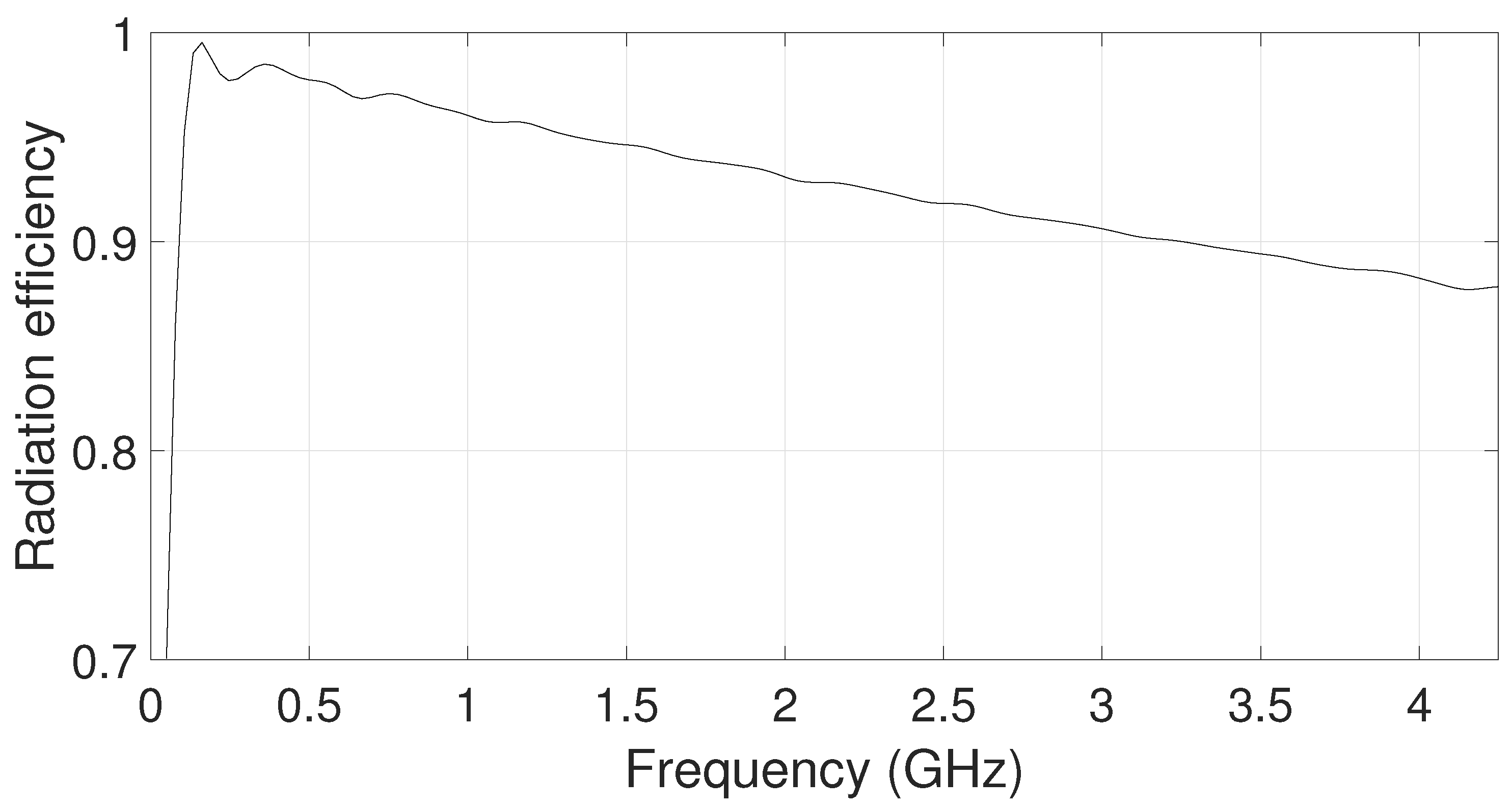
The radiation efficiency as a function of frequency is presented in Figure 12. Between 162 MHz and 4.25 GHz, the efficiency exhibits an approximately linear decreasing trend from the maximum value of 0.99 to 0.88. That is, within the operational bandwidth of the antenna, the efficiency remains consistently above 0.88.

2.6. Radiation Patterns

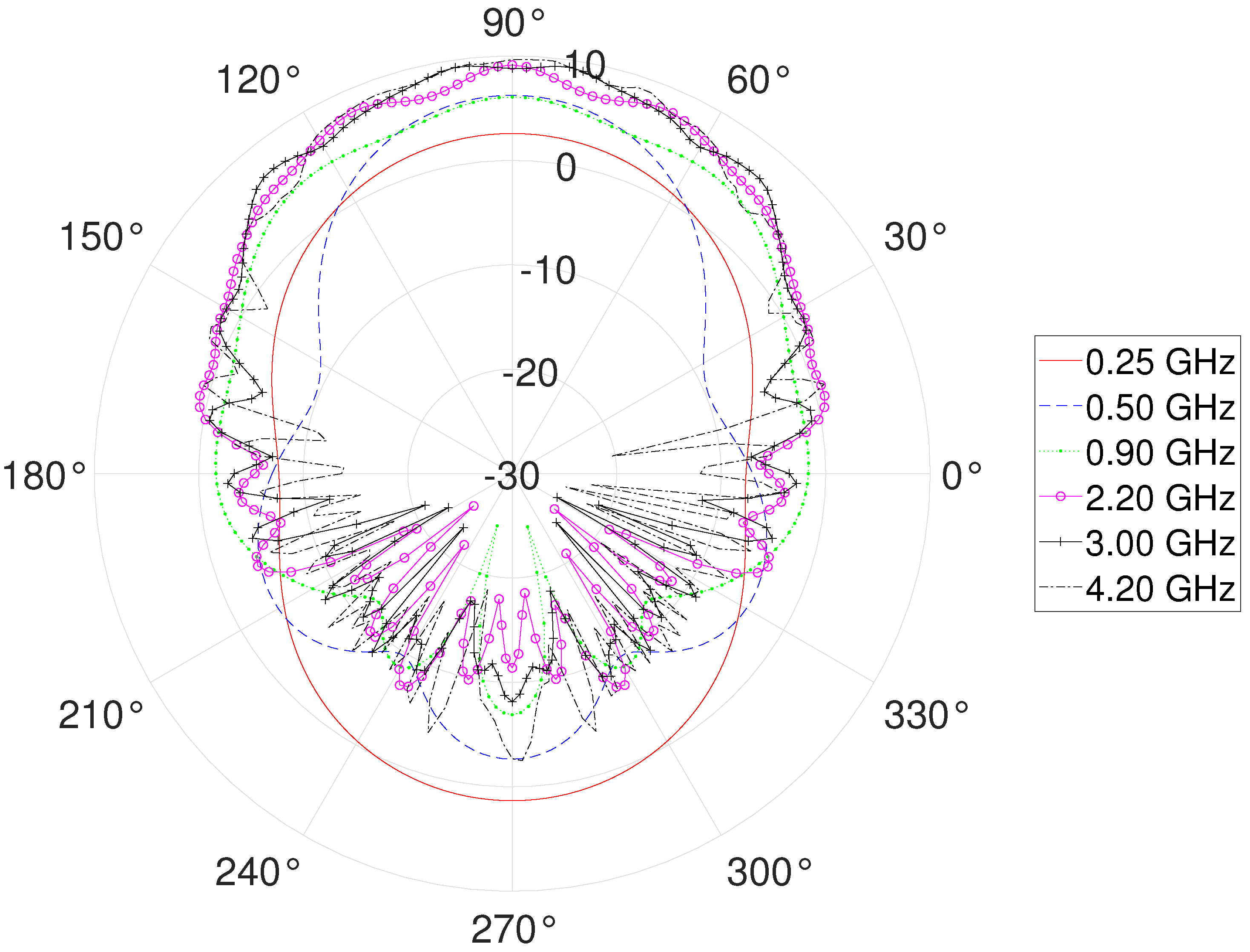
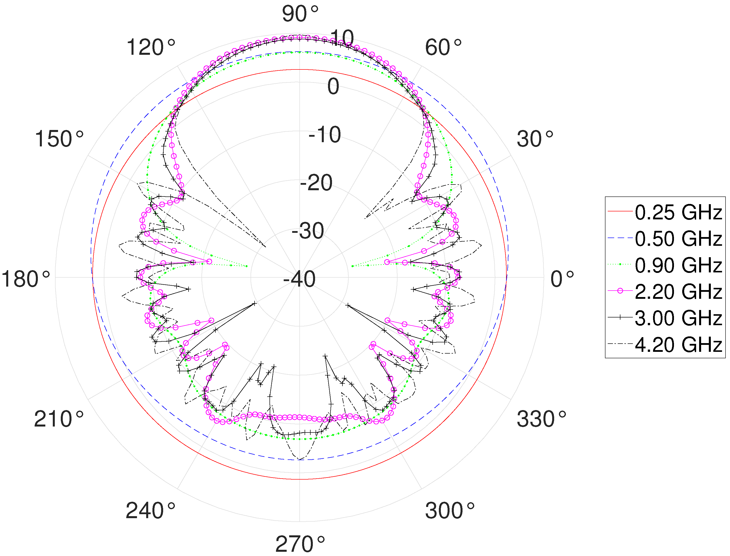
The gain radiation patterns of the antenna are plotted in the E-plane (xy-plane in Figure 3) and H-plane (yz-plane in Figure 3), as shown in Figure 13 and Figure 14, respectively, at frequencies distributed throughout the antenna’s matching range. As the frequency increases, the radiation patterns become progressively more directive toward the front of the antenna (90° in both the E-plane and H-plane).

3. Antenna Testing

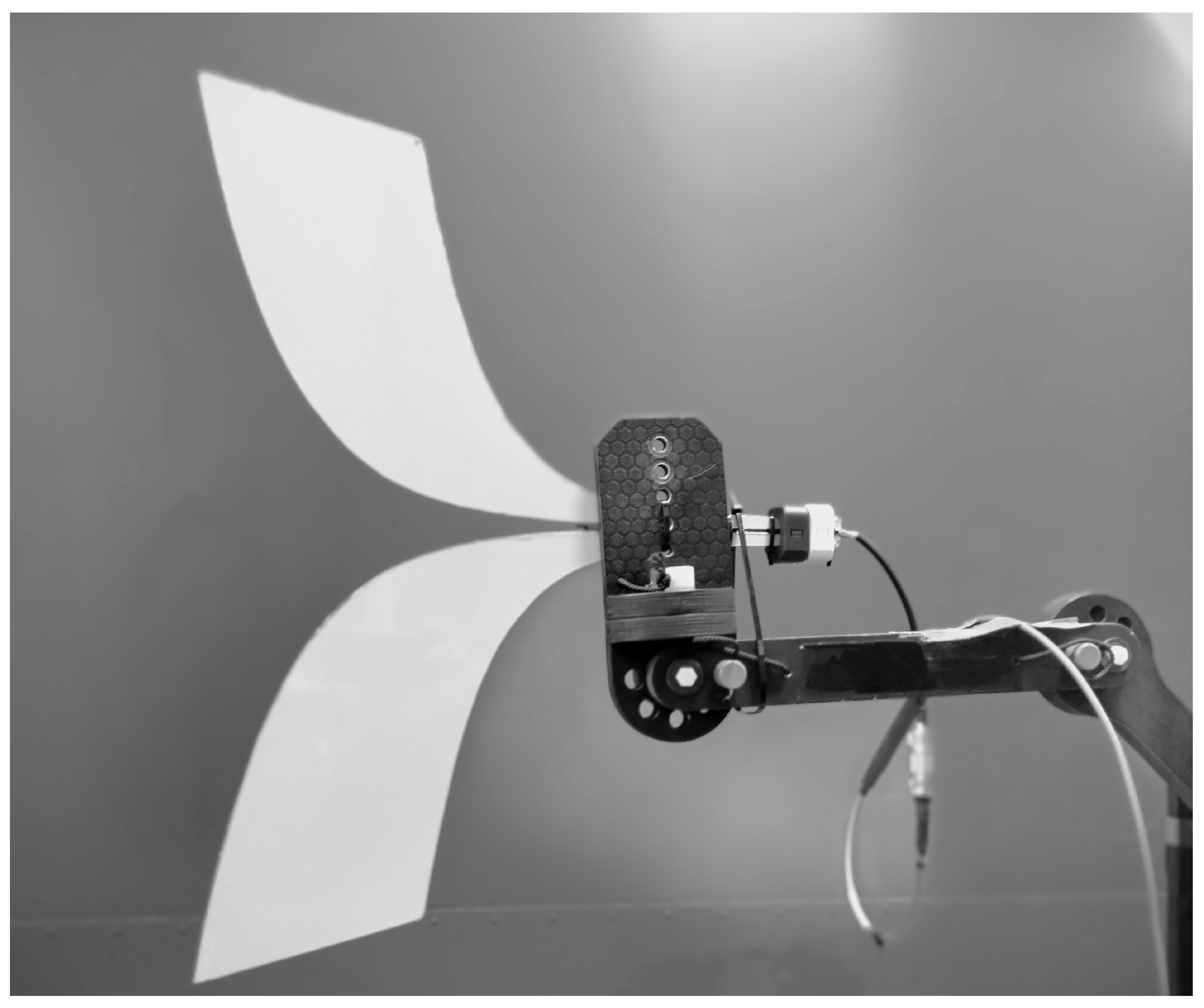
The proposed Vivaldi antenna was fabricated and measured as shown in Figure 15. The arms were implemented with a sheet composed of two layers of aluminium filled with polyester composite. The layered sheet provides the required strength for the arm size and light weight. The total weight of the antenna is less than 600 g. A 3D-printed PLA insulator between the arms was added to adjust the matching impedance. The insulator also enables the antenna to operate at high voltages as discussed before.
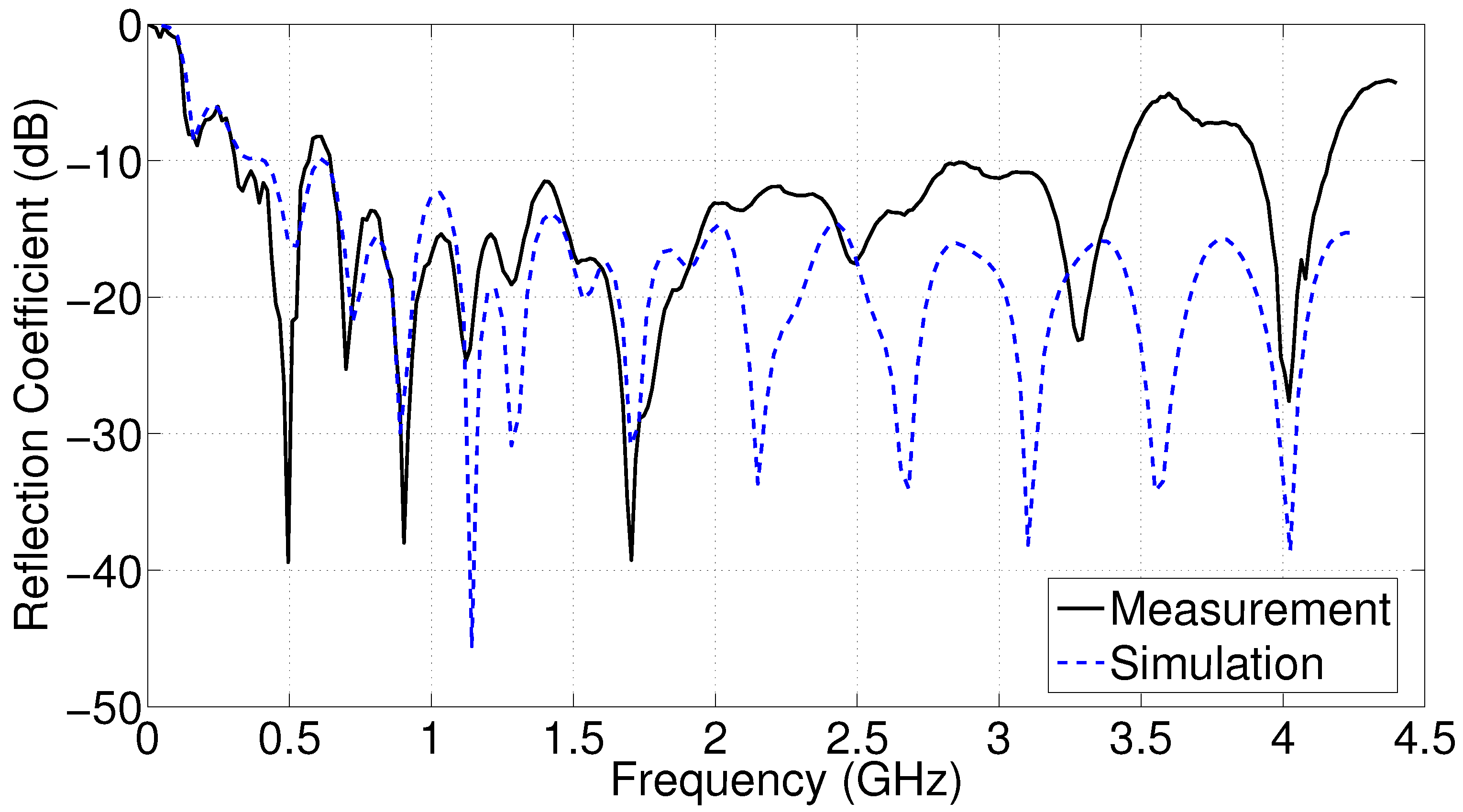
The measurement was conducted using a portable network vector analyzer. Figure 16 shows the measured reflection coefficient of the Vivaldi antenna. The impedance bandwidth obtained from the measurements is 0.61 GHz to 3.44 GHz. A slight impedance mismatch is presented at 600 MHz. It was experimentally identified that common-mode currents were impacting the performance at 600 MHz. Two additional ferrites were added to the design to improve the performance at 600 MHz. Also, the PLA insulator was modified to fill the gap between the insulator and the antenna arms up to 20 cm to maintain the desired transmission line mode in the antenna feed line. The discrepancy between the simulated and measured results is due to the inclusion of elements added during fabrication, which were neglected in the simulation, such as the ferrites and the wooden support.
This impedance bandwidth corresponds to a fractional bandwidth of 1.70, classifying the antenna as an ultra-wideband (UWB) device for radar and communication applications, and as a hyperband (HB) device for electromagnetic interference applications [67].

Radiated Electric Field Measurement

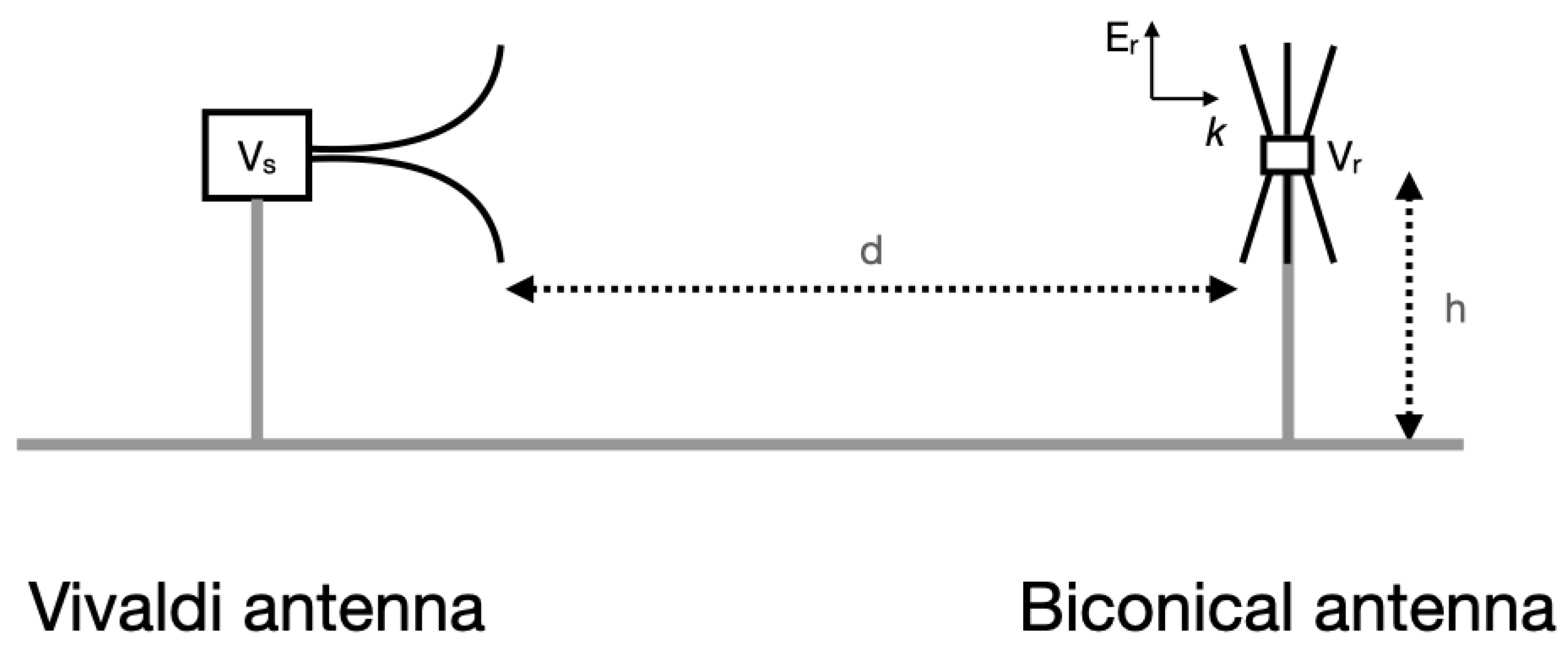
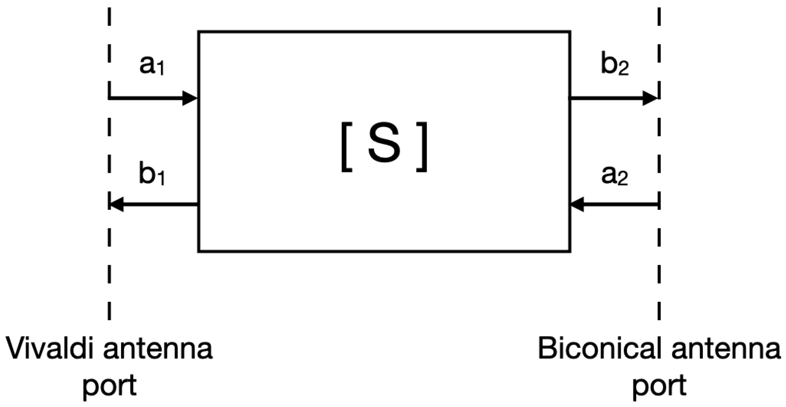
The electric field radiated by the Vivaldi antenna was measured using a reference biconical antenna as shown in Figure 17. Both antennas were h = 1.5 m high and separated by a distance d = 2.9 m. The test was conducted in a covered test area without reflective objects in proximity to the antennas. The test distance and height were selected to represent a typical EMC test scenario in which a reflection from the ground is required. The S-parameters between the reference antenna and the antenna under test were measured, as presented in the diagram of Figure 18, to obtain the transfer function between the incident voltage wave at port 2, b 2 , and the reflected wave at port 1, a 1 . That relationship, shown in (7), is the voltage forward gain (VFG). In our measurement, VFG is the ratio between the received voltage, V r , and the voltage applied to the Vivaldi antenna, V s , in the frequency range where both antennas are impedance matched.
S 21 = b 2 a 1
To calculate the radiated electric field E r , the antenna factor of the receiving antenna A F can be used, as shown in (8):
A F = E r V r
Using (7) and (8), and replacing a 1 and b 2 with V s and V r , respectively, the radiated electric field can be calculated as follows:
E r = A F · S 21 · V s
Figure 17. Measurement setup of the antenna-radiated electric field.
Electronics 15 01749 g017
Figure 18. Diagram of the S-parameter two-port measurement performed to obtain the transfer function of the Vivaldi antenna.
Electronics 15 01749 g018
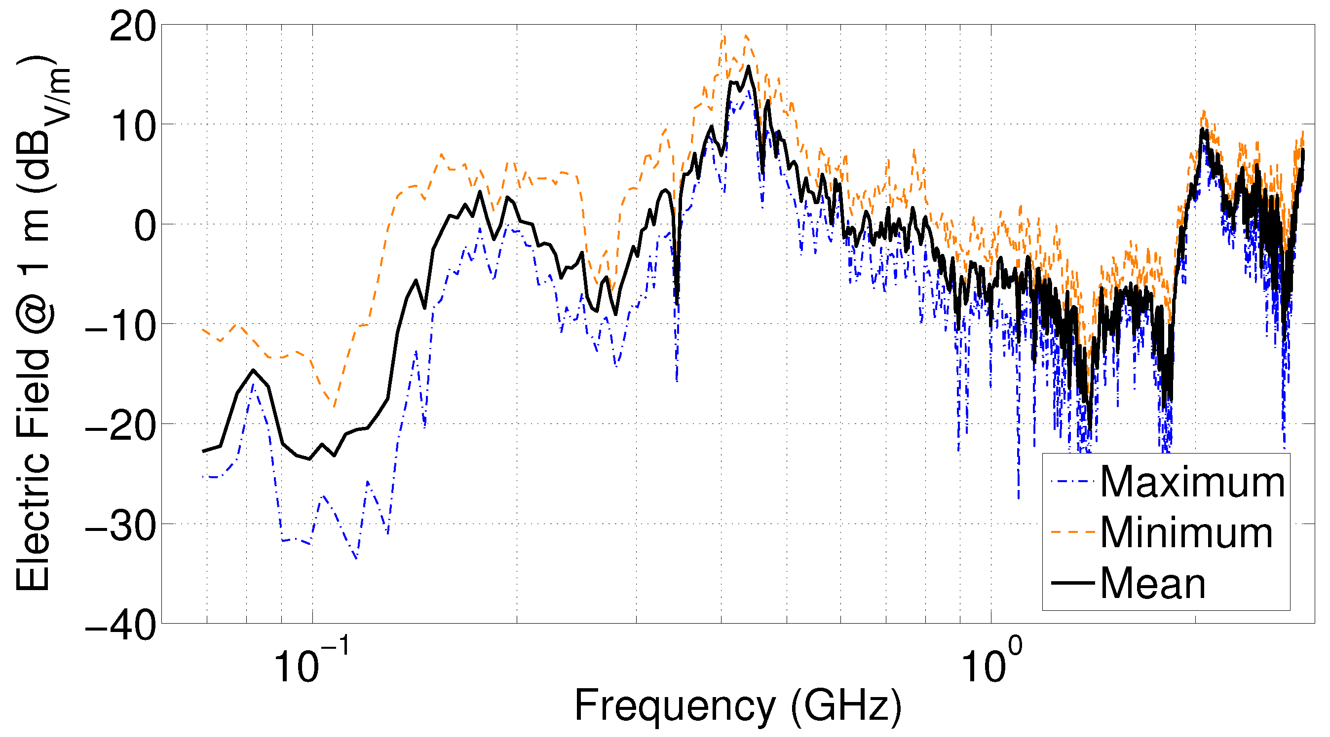
Figure 19 shows the electric field radiated by the Vivaldi antenna scaled to 1 m in vertical polarization. Six measurements were conducted and normalized to 1 m. The figure shows a wideband frequency response with a resonant transfer function between 0.15 and 3 GHz.

4. Time-Domain Characteristics

4.1. Waveform Responses

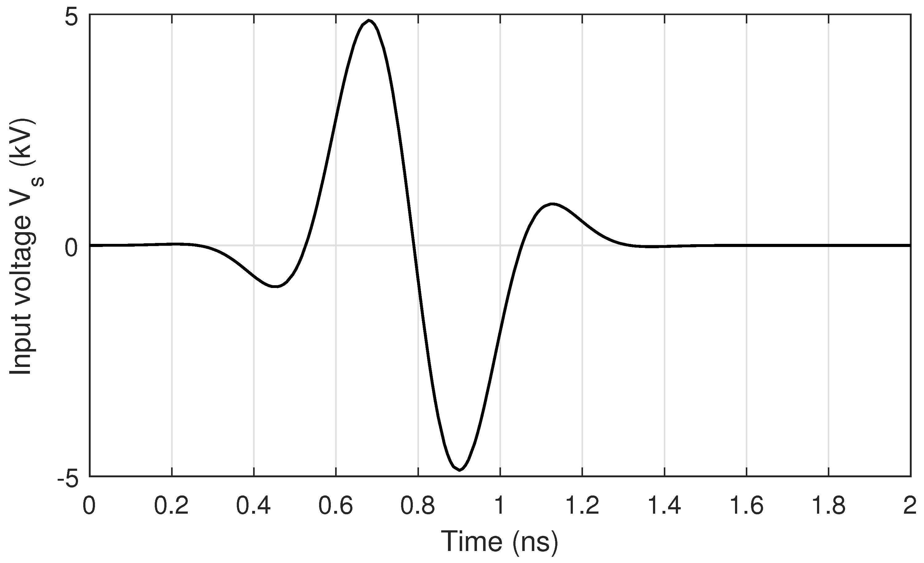
To obtain the received electric field E r for an input signal corresponding to a wideband pulse, in (9), V s is replaced by the pulse shown in Figure 20, whose rise time is 110 ps.
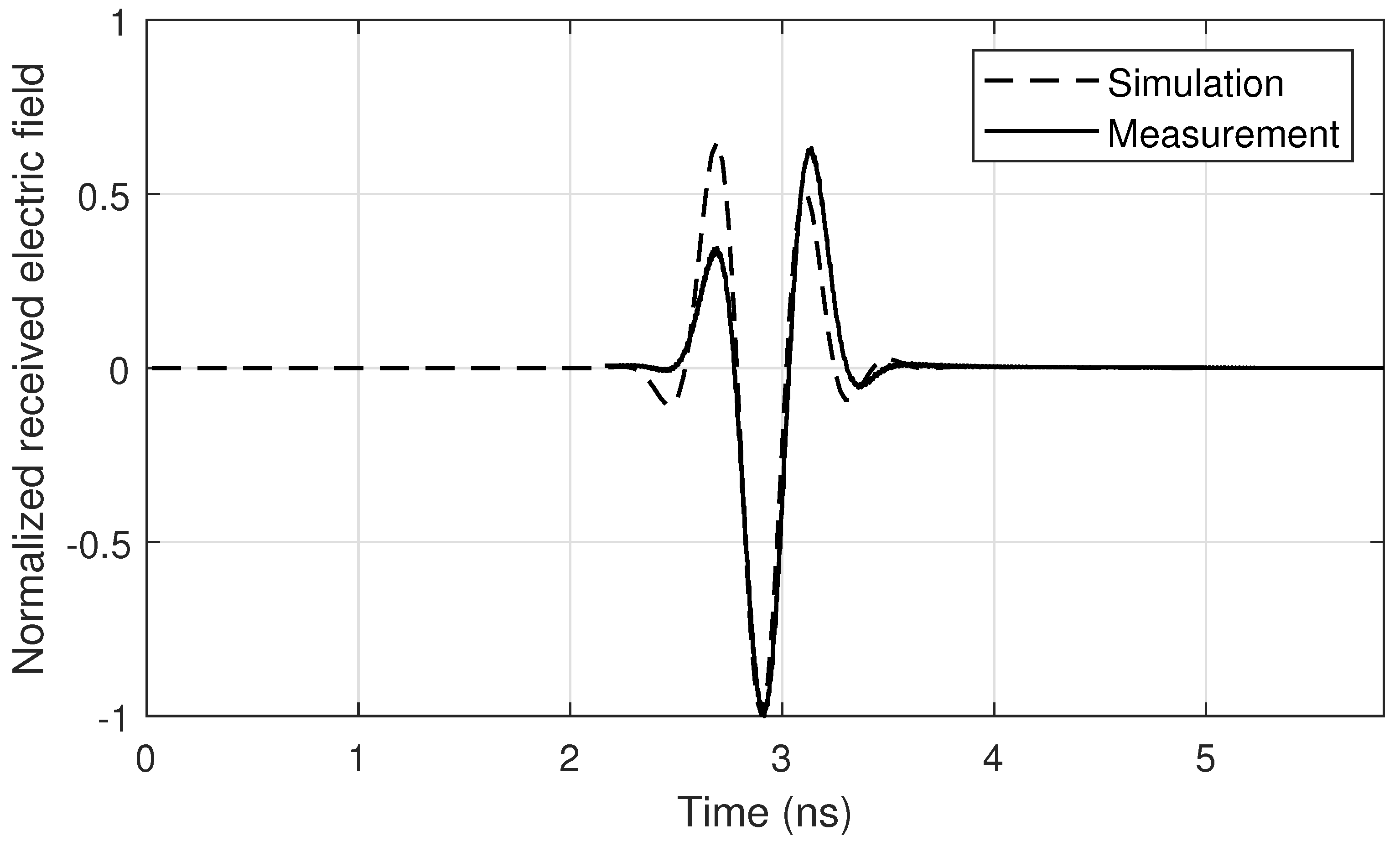
The frequency spectrum obtained for E r is converted to the time domain using the inverse Fourier transform, resulting in the measured pulse presented in Figure 21. The received pulse corresponds to the electric field scaled to 1 m. The figure shows the comparison of the calculated signal and the simulated pulse from Ansys HFSS, obtained as the parameter r E .
In Figure 21, good agreement is observed in the shape and width of the simulated and measured pulses, with small differences in the amplitude and width of the two positive peaks. This figure shows that the radiated electric field waveform is the derivative of the applied voltage typically produced by the Vivaldi antenna [14,68].
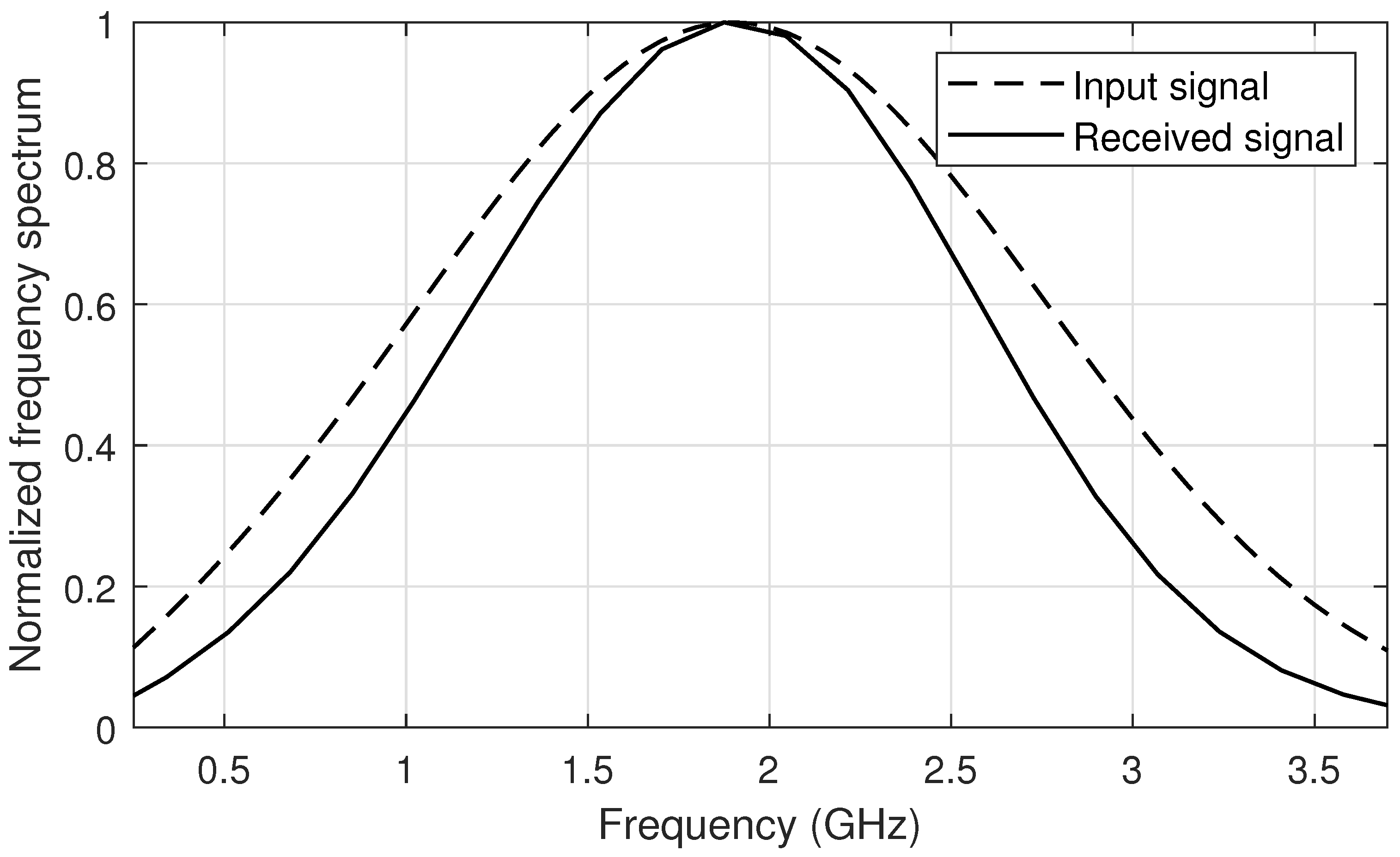
To determine the similarity between the received and the input pulses, they are compared in the frequency domain (Figure 22). The frequency spectra are obtained through the Fourier transform of the pulses. A comparison of the spectra shows that they are centered around the same frequency (1.875 GHz). Despite minor amplitude differences, the spectra satisfactorily include signals within the range of 0.5 GHz to 3.5 GHz.

4.2. Pulse Width Stretch Ratio (SR)

To analyze how the received pulses stretch compared to the input pulse, the parameter pulse width stretch ratio (SR) is used, as defined in (10) and (11) [33,69]:
E s ( t ) = t s ( t ) 2 d t s ( t ) 2 d t
S R = E s 2 1 ( 0.95 ) E s 2 1 ( 0.05 ) E s 1 1 ( 0.95 ) E s 1 1 ( 0.05 )
In the numerator of (11), the width of the pulse of interest (signal s 2 ) is calculated as the time interval between the times where the accumulated pulse energy reaches 5% and 95% of its total energy. This width is compared to that of a reference signal (signal s 1 ), calculated in the same manner, in the denominator of (11).
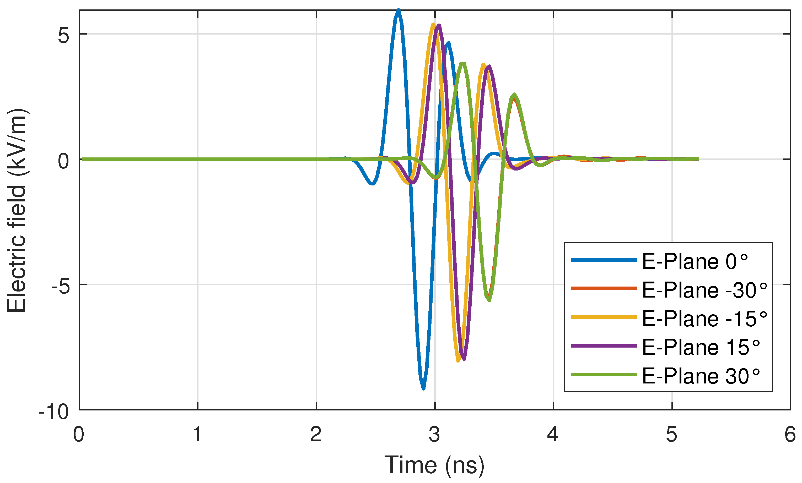
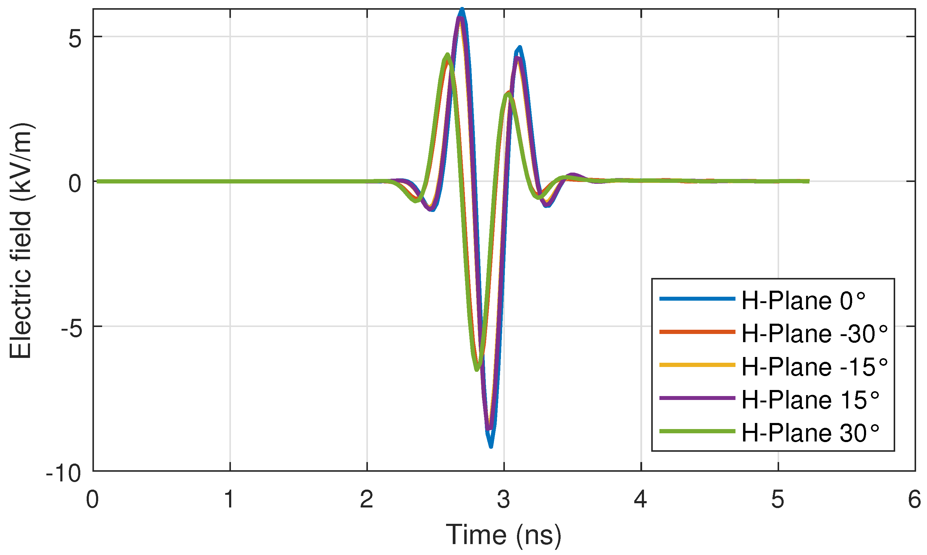
In this case, the pulses of interest, s 2 , correspond to the electric field scaled to a distance of 1 m on the main lobe of the antenna, in both the E-plane and H-plane, at angles of 0° (maximum radiation direction), 15°, 30°, −15°, and −30°. These pulses are shown in Figure 23 and Figure 24.
Two pulses were used as reference signal s 1 in (11): the input voltage V s , shown in Figure 20, and its derivative. The derivative was used because, as previously mentioned, in a pulse-radiating antenna, the radiated electric field has the form of the derivative of the input voltage [14,68]. Since the pulses of interest s 2 are radiated electric fields, it is appropriate to use the derivative of the voltage as a reference. The input voltage itself is also used as a reference to evaluate the stretching of the radiated pulses relative to the driving signal. The pulse width stretch ratio (SR) calculated for the two reference signals s 1 is presented in Table 5 and Table 6.
As expected, the SR value is closer to 1.0 when the derivative of the input voltage is used as the reference. For both reference signals, the SR values increase as the direction moves away from the maximum radiation. Using the input voltage as the reference, the stretching ranges from 33.50% to 40.56%, while using its derivative as the reference, the stretching ranges only from 3.86% to 9.36%. This demonstrates the antenna’s good performance in preserving the input pulse width, by keeping the stretching below 10% when using a reference signal with the same shape as the radiated electric field.
The results in the time domain show that the proposed antenna is suitable to transmit/receive radiated pulses with a rise time as low as 110 ps, maintaining the waveform. Also, it was shown that the pulse-width SR is lower than 10% up to 30° in aperture. These properties are highly desirable for pulsed sensing applications, such as GPR or WPR, since they determine the resolution in space and the capacity of discriminating contiguous objects. The directionality of the antenna provides better performance against interference in the measurements produced by objects located behind the antenna. Directionality is desirable for sensing and also for EMI testing. The 3 dB beamwidth obtained for a pulsed signal, as shown in Figure 23, is 30°.

4.3. Response to Input Pulses with Different Rise Times

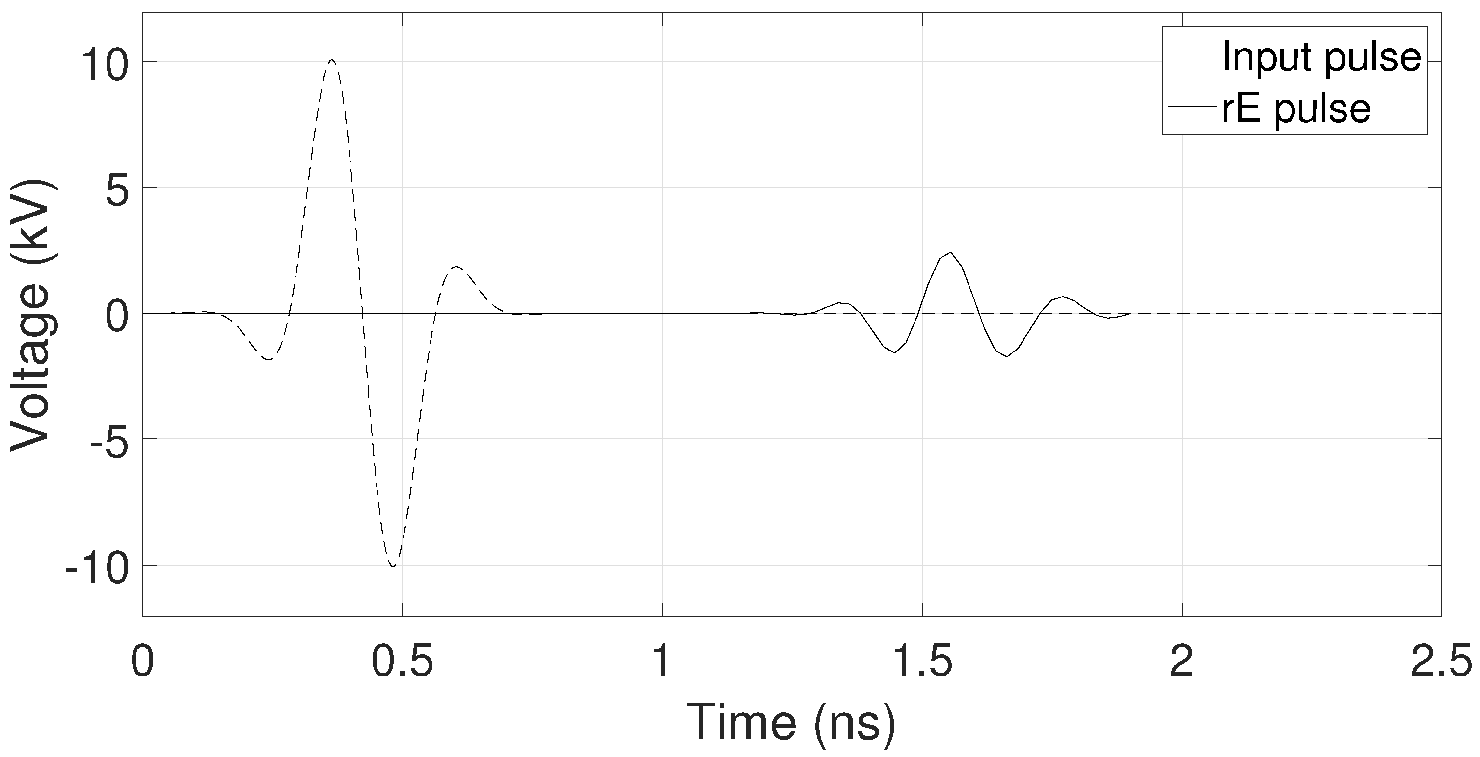
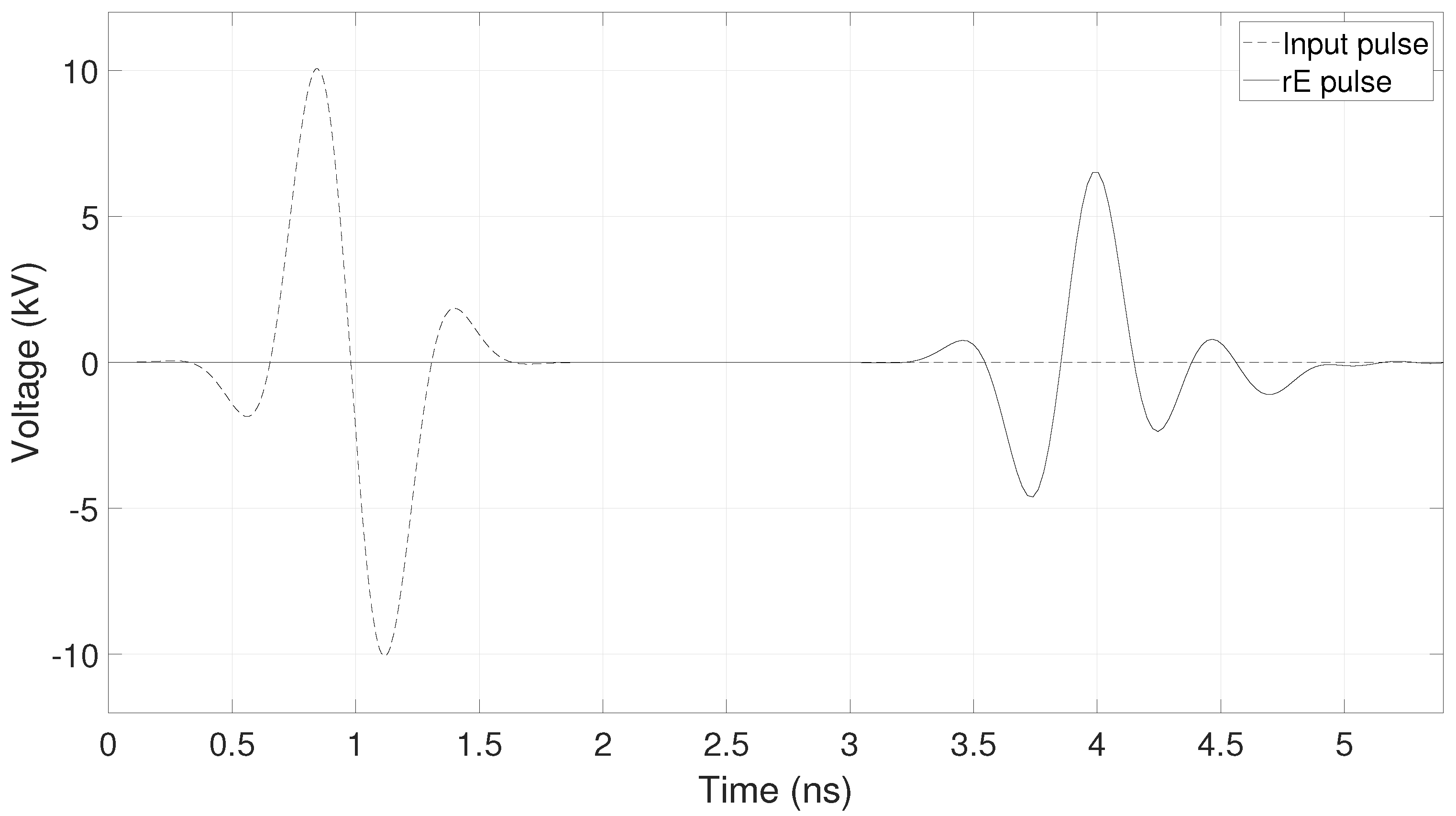
To evaluate the robustness of the antenna’s performance under different pulse widths, the response to input pulses with rise times of 80 ps and 200 ps was analyzed. These values represent a faster and a slower pulse, respectively, compared to the 110 ps rise-time pulse examined in the previous section.
The corresponding responses, expressed in terms of the rE parameter for 0° in the E-plane, are presented in Figure 25 for the 80 ps rise-time input pulse and in Figure 26 for the 200 ps rise-time input pulse. In both figures, the rE waveform exhibits the expected behavior, namely, a shape consistent with the temporal derivative of the input pulse [14,68].
The pulse width stretch ratio (SR) parameter was calculated for the pulses shown in Figure 25 and Figure 26, using the derivative of the input pulse as the reference waveform. The obtained values were 1.1131 and 1.0088 for the pulses with rise times of 80 ps and 200 ps, respectively, demonstrating the good performance of the antenna in preserving the input pulse width for different rise times.

5. Conclusions

The design and verification process for an ultra-wideband high-voltage Vivaldi antenna is presented. The antenna is implemented using a sheet composed of two aluminum layers filled with a polyester composite to reduce its weight. The operational frequency range of the designed antenna was adjusted through a parametric variation on the arms geometry from 0.61 GHz to 3.44 GHz, enabling it to radiate pulses with a rise time of about 110 ps. With the PLA insulator inserted between the arms of the antenna to form an insulated-coplanar-plates transmission line, it can operate at voltages of up to 12.4 kV and can provide broadband impedance matching to a standard 50 Ohm system. This capability makes the designed Vivaldi antenna suitable for applications in electromagnetic compatibility (EMC). The antenna maintains the radiated pulse width very close to that of the driving pulse, achieving a maximum pulse width stretch ratio (SR) of 1.0936 for variations from −30° to 30° in the E-plane and H-plane for a pulse with a 110 ps rise time. This result translates into a low level of distortion in the radiated pulse. It was also shown that the 3 dB beamwidth is 30° for a UWB pulsed signal, which is desirable for sensing and EMI testing.

Author Contributions

Conceptualization, J.J.P.; methodology, J.J.P., O.A.N.M. and H.F.G.-M.; software, O.A.N.M. and H.F.G.-M.; validation, J.J.P., O.A.N.M., H.F.G.-M. and A.P.A.; formal analysis, J.J.P.; investigation, J.J.P., O.A.N.M. and H.F.G.-M.; resources, J.J.P., O.A.N.M., H.F.G.-M. and A.P.A.; data curation, J.J.P. and O.A.N.M.; writing—original draft preparation, J.J.P., O.A.N.M., H.F.G.-M. and A.P.A.; writing—review and editing, J.J.P. and O.A.N.M.; visualization, A.P.A.; supervision, J.J.P.; project administration, O.A.N.M.; funding acquisition, O.A.N.M. and A.P.A. All authors have read and agreed to the published version of the manuscript.

Funding

This research was funded by the Research Directorate of Fundación Universitaria Los Libertadores, Internal Research Call No. 13 of 2025, grant number ING-05-25.

Data Availability Statement

The original contributions presented in the study are included in the article; further inquiries can be directed to the corresponding author.

Conflicts of Interest

Author John J. Pantoja was employed by the company Marshall Land Systems Ltd. The remaining authors declare that the research was conducted in the absence of any commercial or financial relationships that could be construed as a potential conflict of interest.

Abbreviations

The following abbreviations are used in this manuscript:
UWBUltra-Wideband
EMCElectromagnetic Compatibility
EMIElectromagnetic Interference
TWRThrough-Wall Radar
TSATapered Slot Antenna
GPRGround-Penetrating Radar
RCReverberation Chamber
IEMIIntentional Electromagnetic Interference
DUTDevice Under Test
AVAAntipodal Vivaldi Antenna
SRPulse Width Stretch Ratio
PLAPolylactic Acid
HFSSHigh Frequency Structure Simulator
VNAVector Network Analyzer
HBHyperband
AFAntenna Factor
VFGVoltage Forward Gain

References

  1. Yadav, R.; Malviya, L. UWB antenna and MIMO antennas with bandwidth, band-notched, and isolation properties for high-speed data rate wireless communication: A review. Int. J. Microw. Comput. Aided Eng. 2020, 30, e22033. [Google Scholar] [CrossRef]
  2. Ibrahim, A.A.; Machac, J.; Shubair, R.M. UWB MIMO Antenna for High Speed Wireless Applications. Appl. Comput. Electromagn. Soc. J. (ACES) 2019, 34, 1294–1299. [Google Scholar]
  3. Zakeri, H.; Azizpour, R.; Khoddami, P.; Moradi, G.; Alibakhshikenari, M.; Hwang See, C.; Denidni, T.A.; Falcone, F.; Koziel, S.; Limiti, E. Low-Cost Multiband Four-Port Phased Array Antenna for Sub-6 GHz 5G Applications with Enhanced Gain Methodology in Radio-Over-Fiber Systems Using Modulation Instability. IEEE Access 2024, 12, 117787–117799. [Google Scholar] [CrossRef]
  4. Wong, K.L.; Hong, S.E.; Li, W.Y. Low-Profile Four-Port MIMO Antenna Module Based 16-Port Closely-Spaced 2 × 2 Module Array for 6G Upper Mid-Band Mobile Devices. IEEE Access 2023, 11, 110796–110808. [Google Scholar] [CrossRef]
  5. Elmansouri, M.A.; Filipovic, D.S. Pulse Distortion and Mitigation Thereof in Spiral Antenna-Based UWB Communication Systems. IEEE Trans. Antennas Propag. 2011, 59, 3863–3871. [Google Scholar] [CrossRef]
  6. Cicchetti, R.; Miozzi, E.; Testa, O. Wideband and UWB Antennas for Wireless Applications: A Comprehensive Review. Int. J. Antennas Propag. 2017, 2017, 2390808. [Google Scholar] [CrossRef]
  7. Elsheakh, D.M.; Abdallah, E.A. Compact shape of vivaldi antenna for water detection using ground pentrating radar. Microw. Opt. Technol. Lett. 2014, 56, 1801–1809. [Google Scholar] [CrossRef]
  8. Sato, M.; Hamada, Y.; Feng, X.; Kong, F.N.; Zeng, Z.; Fang, G. GPR using an array antenna for landmine detection. Near Surf. Geophys. 2004, 2, 7–13. [Google Scholar] [CrossRef]
  9. Kumar, O.P.; Kumar, P.; Ali, T.; Kumar, P.; Vincent, S. Ultrawideband Antennas: Growth and Evolution. Micromachines 2022, 13, 60. [Google Scholar] [CrossRef]
  10. Rafique, U.; Pisa, S.; Cicchetti, R.; Testa, O.; Cavagnaro, M. Ultra-Wideband Antennas for Biomedical Imaging Applications: A Survey. Sensors 2022, 22, 3230. [Google Scholar] [CrossRef]
  11. Latha, T.; Ram, G.; Kumar, G.A.; Chakravarthy, M. Review on Ultra-Wideband Phased Array Antennas. IEEE Access 2021, 9, 129742–129755. [Google Scholar] [CrossRef]
  12. Jamshidi-Zarmehri, H.; Akbari, A.; Labadlia, M.; Kedze, K.E.; Shaker, J.; Xiao, G.; Amaya, R.E. A Review on Through-Wall Communications: Wall Characterization, Applications, Technologies, and Prospects. IEEE Access 2023, 11, 127837–127854. [Google Scholar] [CrossRef]
  13. Ghimire, J.; Choi, D.Y. Ultra-Wide Band Double-Slot Podal and Antipodal Vivaldi Antennas Feed by Compact out-of-Phase Power Divider Slot for Fluid Properties Determination. Sensors 2022, 22, 4543. [Google Scholar] [CrossRef]
  14. Sanjay D, R.; Azeemuddin, S. A comprehensive review of high voltage wideband and ultra-wide band antennas for IEMI applications. Eng. Res. Express 2021, 3, 012001. [Google Scholar] [CrossRef]
  15. Gibson, P. The Vivaldi Aerial. In Proceedings of the 1979 9th European Microwave Conference, Brighton, UK, 17–20 September 1979; pp. 101–105. [Google Scholar] [CrossRef]
  16. Bhattacharjee, A.; Bhawal, A.; Karmakar, A.; Saha, A.; Bhattacharya, D. Vivaldi antennas: A historical review and current state of art. Int. J. Microw. Wirel. Technol. 2021, 13, 833–850. [Google Scholar] [CrossRef]
  17. Gutierrez, S.; Pantoja, J.J.; Ruiz, E.F.; González, N.; Vega, F.; Baer, C.; Sachs, J.; Kasmi, C. Advances on the detection of Landmines and IEDs in Colombia using UWB GPR and Machine Learning Techniques. In Proceedings of the 2021 15th European Conference on Antennas and Propagation (EuCAP), Düsseldorf, Germany, 22–26 March 2021; pp. 1–4. [Google Scholar] [CrossRef]
  18. Al Mesmari, A.; Pantoja, J.J.; Alvarez, J.; Banelli, A.; Bega, F.; Kasmi, C. An Unmanned Aerial Vehicle Platform for the detection of Landmines and IEDs using GPR. In Proceedings of the GlobalEM 2022, Abu Dhabi, United Arab Emirates, 13–17 November 2022; pp. 101–102. [Google Scholar]
  19. García-Fernández, M.; López, Y.Á.; Andrés, F.L.H. Airborne Multi-Channel Ground Penetrating Radar for Improvised Explosive Devices and Landmine Detection. IEEE Access 2020, 8, 165927–165943. [Google Scholar] [CrossRef]
  20. Stadler, S.; Igel, J. Developing Realistic FDTD GPR Antenna Surrogates by Means of Particle Swarm Optimization. IEEE Trans. Antennas Propag. 2022, 70, 4259–4272. [Google Scholar] [CrossRef]
  21. Stadler, S.; Schennen, S.; Hiller, T.; Igel, J. Realistic simulation of GPR for landmine and IED detection including antenna models, soil dispersion and heterogeneity. Near Surf. Geophys. 2024, 22, 188–205. [Google Scholar] [CrossRef]
  22. Pantoja, J.J.; Gutierrez, S.; Pineda, E.; Martinez, D.; Baer, C.; Vega, F. Modeling and Measurement of Complex Permittivity of Soils in UHF. IEEE Geosci. Remote. Sens. Lett. 2020, 17, 1109–1113. [Google Scholar] [CrossRef]
  23. Marvin, A.C.; Esposito, G.; Dawson, J.F.; Flintoft, I.D.; Dawson, L.; Everard, J.A.K.; Melia, G.C.R. A wide-band hybrid antenna for use in reverberation chambers. In Proceedings of the 2013 IEEE International Symposium on Electromagnetic Compatibility, Denver, CO, USA, 5–9 August 2013; pp. 222–226. [Google Scholar] [CrossRef]
  24. Pantoja, J.J.; Bucheli, V.; Ross, D. Electromagnetic side-channel attack risk assessment on a practical quantum-key-distribution receiver based on multi-class classification. Epj Quantum Technol. 2024, 11, 78. [Google Scholar] [CrossRef]
  25. Pantoja, J.J.; Tello, A.; Anagnostou, D.; Kirrane, J.; Stonehouse, M.; Koehler-Sidki, A.; Natrella, M.; Donaldson, R. Radiofrequency emanations of a single-photon detector. IET Conf. Proc. 2023, 2023, 55–59. [Google Scholar] [CrossRef]
  26. Mandaris, D.; Leferink, F. Simulation and measurement of log-periodic antenna and double ridged guide horn antenna for optimised field uniformity. In Proceedings of the 2017 International Symposium on Electromagnetic Compatibility—EMC EUROPE, Angers, France, 4–8 September 2017; pp. 1–6. [Google Scholar] [CrossRef]
  27. Ivšić, B.; Friščić, F.; Dadić, M.; Muha, D. Design and Analysis of Vivaldi Antenna for Measuring Electromagnetic Compatibility. In Proceedings of the 2019 42nd International Convention on Information and Communication Technology, Electronics and Microelectronics (MIPRO), Opatija, Croatia, 20–24 May 2019; pp. 491–495. [Google Scholar] [CrossRef]
  28. Dawson, J.F.; Hoad, R.; Petit, B.; Rees, T.; Robinson, M.; Bale, S.; Hough, M.; Dawson, L.; Marvin, A.; Will, I. A Lightweight, Compact, High voltage Hyperband Antenna for IEMI Testing. In Proceedings of the 2021 IEEE International Joint EMC/SI/PI and EMC Europe Symposium, Virtual, 26 July–20 August 2021; p. 154. [Google Scholar] [CrossRef]
  29. Dawson, J.F.; Bale, S.J.; Robinson, M.P.; Rees, T.; Petit, B.J.; Hoad, R.; Hough, M. A Pulse Antenna Suite for IEMI Testing. IEEE Electromagn. Compat. Mag. 2024, 13, 44–57. [Google Scholar] [CrossRef]
  30. Ohm, S.; Kang, E.; Lim, T.H.; Choo, H. Design of a Dual-Polarization All-Metal Vivaldi Array Antenna Using a Metal 3D Printing Method for High-Power Jamming Systems. IEEE Access 2023, 11, 35175–35181. [Google Scholar] [CrossRef]
  31. Savostin, V.S.; Gevorkyan, A.V. Ultra-Wideband 10-Element Antipodal Vivaldi Antenna Array with Metallic Insert. In Proceedings of the 2023 Radiation and Scattering of Electromagnetic Waves (RSEMW), Divnomorskoe, Russia, 26–30 June 2023; pp. 420–423. [Google Scholar] [CrossRef]
  32. Xie, J.; Chen, C.; He, J.; Qiao, H.; Fang, X.; Qu, T.; An, J. A Bidirectional Bent Vivaldi-Connected Array with Short-Circuited Branches for UWB Pulse Radiation. IEEE Trans. Antennas Propag. 2024, 72, 9177–9187. [Google Scholar] [CrossRef]
  33. Peng, L.; Xie, J.Y.; Li, X.F.; Jiang, X. Front to Back Ratio Bandwidth Enhancement of Resonance Based Reflector Antenna by Using a Ring-Shape Director and Its Time-Domain Analysis. IEEE Access 2017, 5, 15318–15325. [Google Scholar] [CrossRef]
  34. Çolak, S.A.; Tokan, N.T. Time-Domain Analysis of Modified Vivaldi Antennas. In Antennas and Wave Propagation; Pinho, P., Ed.; IntechOpen: Rijeka, Croatia, 2018; Chapter 3. [Google Scholar] [CrossRef]
  35. Amador, M.; Rouco, A.; Albuquerque, D.; Pinho, P. Overview of Vivaldi Antenna Selection for Through-Wall Radar Applications. Sensors 2024, 24, 6536. [Google Scholar] [CrossRef]
  36. Lee, D.; Raman, S.; Augustine, R. Design and Investigation on Antipodal Vivaldi Antenna Emitting a Pulse-Like Waveform for Imaging Close-Range Objects. IEEE Access 2024, 12, 135642–135650. [Google Scholar] [CrossRef]
  37. Özmen, H.; Izci, D.; Rizk-Allah, R.M.; Ekinci, S.; Dalarsson, M. Optimization of split-ring resonator slots using levy-opposition-enhanced Newton Raphson method for high-gain UWB Vivaldi antenna design. Sci. Rep. 2026, 16, 7828. [Google Scholar] [CrossRef]
  38. Zhang, W.; Shi, L.; Zhao, C.; Yang, R. High-Gain Miniaturized Ultrawideband Antipodal Vivaldi Antenna with Metamaterials. Micromachines 2026, 17, 8. [Google Scholar] [CrossRef]
  39. Guo, M.; Song, J.; Yan, X.; Zeng, H.; Huang, X.; Yang, B.; Xie, S. UWB, High-Isolation Asymmetric Vivaldi Antenna Array Loaded with Composite Decoupling Structure. IEEE Antennas Wirel. Propag. Lett. 2026. early access. [Google Scholar] [CrossRef]
  40. Zhao, Q.; Chen, Y.; Li, M.; Wang, J. Synergistically Optimized Vivaldi Array with SSPP Decoupling and Metasurface Gain Enhancement. Prog. Electromagn. Res. Lett. 2026, 116, 55–61. [Google Scholar] [CrossRef]
  41. Wang, B.; Ning, H.; Yan, Y.; Wang, Y.; Li, X. Dual-plane Vivaldi antenna with inherent reflection suppression for UWB pulse applications. AEU Int. J. Electron. Commun. 2025, 179, 156180. [Google Scholar] [CrossRef]
  42. Hoang, H.; Nguyen, M.H.; Pham-Xuan, V. Guidance and absorption of internal energy in Vivaldi antennas using multiple slots, full-band dividers, metamaterials, and distributed resistors. Sci. Rep. 2026, 16, 10112. [Google Scholar] [CrossRef] [PubMed]
  43. Zhao, G.; Xiao, Y.; Huang, W.; Xu, S.; Chen, Z. Compact and Gain-Enhanced Vivaldi Antenna Design Using Nonuniform Slot Profile Optimization and Aperture Dielectric Loading. IEEE Antennas Wirel. Propag. Lett. 2025, 24, 1570–1574. [Google Scholar] [CrossRef]
  44. Penagaluru, K.; KK, S.; Kumari, P.; Gupta, V.; Sutrakar, V.K. High Gain Low RCS Broad-Band Antipodal Vivaldi Antenna. In Proceedings of the 2025 IEEE Microwaves, Antennas, and Propagation Conference (MAPCON), Kochi, India, 14–18 December 2025; pp. 1–4. [Google Scholar] [CrossRef]
  45. Sutradhar, P.; Hasan, K.N.; Ahmed, S. Design and Simulation of a UWB Vivaldi Antenna and Its Array Configuration for S, C, and X Band Applications. In Proceedings of the 2025 International Conference on Quantum Photonics, Artificial Intelligence, and Networking (QPAIN), Saidpur, Bangladesh, 31 July–2 August 2025; pp. 1–6. [Google Scholar] [CrossRef]
  46. Wang, Y.; Ao, M.; Su, J.; Guo, Q.; Li, Z. An ultra-wideband triple-polarization reconfigurable Vivaldi array antenna. AEU Int. J. Electron. Commun. 2025, 188, 155575. [Google Scholar] [CrossRef]
  47. Nurhayati, N.; Setyono, M.I.A.; Al-Gburi, A.J.; Anifah, L.; Rakhmawati, L.; Iskandarianto, F.A.; Ali, U. Studies of corrugated antipodal vivaldi wideband antenna with notched band and rectenna integration. Prime Adv. Electr. Eng. Electron. Energy 2025, 14, 101112. [Google Scholar] [CrossRef]
  48. Schwarzbeck. Schwarzbeck Mess-Elektronik OHG. TEMH 6000–Broadband TEM Horn Antenna. 2021. Available online: https://www.schwarzbeck.com/antennas/broadband-horn-antennas/tem-horn-antennas/temh-6000/ (accessed on 22 March 2026).
  49. A.H. Systems. SAS-570 Double Ridge Guide Horn Antenna: 170 MHz–3 GHz; Datasheet. Frequency Range: 170 MHz–3 GHz. Gain: 0–10.9 dBi. Maximum Continuous Power: 800 W CW. Impedance: 50 Ω. Connector: N-Type Female; A.H. Systems: Chatsworth, CA, USA, 2026. [Google Scholar]
  50. Reliant EMC LLC. LB-225 Broadband Horn Antenna; Datasheet (File Name: tr_LB-225.pdf); Reliant EMC LLC.: Signal Hill, CA, USA, 2020; Available online: https://www.reliantemc.com/download/A-Info/tr_LB-225.pdf (accessed on 22 March 2026).
  51. Reliant EMC LLC. LB-460 Broadband Horn Antenna; Datasheet (File Name: tr_LB-460.pdf); Reliant EMC LLC.: Signal Hill, CA, USA, 2020; Available online: https://www.reliantemc.com/download/A-Info/tr_LB-460.pdf (accessed on 22 March 2026).
  52. ETS-Lindgren L.P. Model 3106B Double-Ridged Waveguide Horn User Manual; Part #399785, Rev. B. Covers frequency range 200 MHz–2.5 GHz; ETS-Lindgren L.P.: Cedar Park, TX, USA, 2008. [Google Scholar]
  53. ETS-Lindgren Inc. Models 3112, 3106B, 3119, 3115, 3117, 3116C Double-Ridged Waveguide Horn Antennas User Manual; Part #399318, Rev. D. Covers Frequency Range 100 MHz–40 GHz Depending on Model; ETS-Lindgren Inc.: Cedar Park, TX, USA, 2014. [Google Scholar]
  54. Schwarzbeck Mess-Elektronik OHG. BBHA 9120 F—Double Ridge Broadband Horn Antenna; Datasheet Valid for SN:450 (N)/SN:3050 (7/16) and Higher; Schwarzbeck Mess-Elektronik OHG: Schönau, Germany, 2024. [Google Scholar]
  55. Arthur, P.; Kromer, M.; Harter, M. Low Frequency Edge-Slot Vivaldi Antenna for Ground Penetrating Radar Applications. In Proceedings of the 2024 25th International Microwave and Radar Conference (MIKON), Wroclaw, Poland, 1–4 July 2024; pp. 160–162. [Google Scholar] [CrossRef]
  56. Riyanti, K.P.K.; Setijadi, E.; Hendrantoro, G.; Nurhayati, N. Optimizing Vivaldi Antenna Performance: Feeding Strategies for Broadband GPR Bandwidth Expansion. In Proceedings of the 2024 IEEE Asia-Pacific Conference on Applied Electromagnetics (APACE), Langkawi, Malaysia, 21–23 December 2024; pp. 270–273. [Google Scholar] [CrossRef]
  57. De, S.; Kundu, S. A Planar E Shaped Antipodal Vivaldi Antenna with Elliptical Slots for GPR Application. In Proceedings of the 2024 Second International Conference on Microwave, Antenna and Communication (MAC), Dehradun, India, 4–6 October 2024; pp. 1–4. [Google Scholar] [CrossRef]
  58. Sharma, A.; Goel, K.; Prajapati, J.; Upadhayay, M.D. S- Band GPR using Vivaldi for Object Detection. In Proceedings of the 2024 IEEE International Conference for Women in Innovation, Technology & Entrepreneurship (ICWITE), Bangalore, India, 16–17 February 2024; pp. 675–679. [Google Scholar] [CrossRef]
  59. Ranjan, P.; Raj, R.; Prakash, T. Suspended Elliptical Slot-Based High Gain Antenna for GPR Application. In Proceedings of the 2024 IEEE International Conference on Interdisciplinary Approaches in Technology and Management for Social Innovation (IATMSI), Gwalior, India, 14–16 March 2024; Volume 2, pp. 1–4. [Google Scholar] [CrossRef]
  60. Wu, J.; Ma, J.; Shi, B.; Mo, K.S.; Peng, L. Design of an Ultra-Wideband Low-Profile Directional Bowtie Antenna for Ground-Penetrating Radars. In Proceedings of the 2024 International Conference on Microwave and Millimeter Wave Technology (ICMMT), Beijing, China, 16–19 May 2024; Volume 1, pp. 1–3. [Google Scholar] [CrossRef]
  61. Matsepe, L.; Steyn, W.; Grootboom, L. UWB Slot Bow-tie Antenna for FMCW GPR Applications. In Proceedings of the 2024 IEEE-APS Topical Conference on Antennas and Propagation in Wireless Communications (APWC), Lisbon, Portugal, 2–6 September 2024; pp. 91–94. [Google Scholar] [CrossRef]
  62. Ali, M.U.; Abdulrazak, L.F.; Iqbal, J.; Illahi, U.; Kiani, G.I.; Khan, R.A.; Elmannai, H. Design of an optimized low-profile UWB rectangular dielectric resonator antenna with moon-shaped ground for 5G—Millimeter wave applications. AEU Int. J. Electron. Commun. 2025, 200, 155903. [Google Scholar] [CrossRef]
  63. Mohamed, H.A.; Aboualalaa, M. A low profile super UWB- MIMO antenna with d-shaped for satellite communications, 5G and beyond applications. Sci. Rep. 2025, 15, 15660. [Google Scholar] [CrossRef]
  64. Awan, W.A.; Abbas, A.; Choi, D.; Sufian, M.A.; Hussain, N.; Kim, N. Precision Enhancement in EMC Measurements: Optimizing Multi-Layer Lens for Horn Antenna Applications. In Proceedings of the 2024 International Symposium on Antennas and Propagation (ISAP), Incheon, Republic of Korea, 5–8 November 2024; pp. 1–2. [Google Scholar] [CrossRef]
  65. Kubo, T.; Ishida, T.; Harima, K.; Gotoh, K. Radiation Characteristics of TEM Horn and Broadband Sleeve Antennas Used for Near-Field Radiated Immunity Test. In Proceedings of the 2024 IEEE Joint International Symposium on Electromagnetic Compatibility, Signal & Power Integrity: EMC Japan/Asia-Pacific International Symposium on Electromagnetic Compatibility (EMC Japan/APEMC Okinawa), Okinawa, Japan, 20–24 May 2024; pp. 607–608. [Google Scholar] [CrossRef]
  66. Stutzman, W.; Thiele, G. Antenna Theory and Design; John Wiley & Sons: Hoboken, NJ, USA, 2012. [Google Scholar]
  67. Sabath, F.; Mokole, E.; Samaddar, S. Definition and Classification of Ultra-Wideband Signals and Devices. URSI Radio Sci. Bull. 2005, 2005, 12–26. [Google Scholar]
  68. Farr, E.G.; Baum, C.E.; Buchenauer, C.J. Impulse Radiating Antennas, Part II. In Ultra-Wideband, Short-Pulse Electromagnetics 2; Carin, L., Felsen, L.B., Eds.; Springer: Boston, MA, USA, 1995; pp. 159–170. [Google Scholar] [CrossRef]
  69. Yang, Y.Y.; Chu, Q.X.; Zheng, Z.A. Time Domain Characteristics of Band-Notched Ultrawideband Antenna. IEEE Trans. Antennas Propag. 2009, 57, 3426–3430. [Google Scholar] [CrossRef]
Figure 1. Ultra-Wideband Antenna Applications: (a) Detecting Buried Objects, (b) Airborne GPR, (c) Through-Wall Radar, (d) Microwave Tomography, (e) Microwave Imaging, (f) Fluid Characterization, (g) Wideband Communications, (h) IEMI or EMC, and (i) Water Detection.
Electronics 15 01749 g001
Figure 2. Workflow followed in this study.
Electronics 15 01749 g002
Figure 5. Comparison of the simulated reflection coefficient of the antenna with and without the PLA insulator between the arms.
Electronics 15 01749 g005
Figure 11. Maximum gain of the proposed Vivaldi antenna.
Electronics 15 01749 g011
Figure 12. Radiation efficiency of the proposed Vivaldi antenna.
Electronics 15 01749 g012
Figure 13. Gain radiation patterns in the E-plane.
Electronics 15 01749 g013
Figure 14. Gain radiation patterns in the H-plane.
Electronics 15 01749 g014
Figure 15. Ultra-wideband antenna and wooden support attached to the testing mast.
Electronics 15 01749 g015
Figure 16. Input reflection coefficient of the implemented antenna.
Electronics 15 01749 g016
Figure 19. Received electric field scaled to 1 m and normalized to 1 V at the antenna port. Mean, maximum, and minimum values of 6 tests.
Electronics 15 01749 g019
Figure 20. Pulse V s applied to the Vivaldi antenna input.
Electronics 15 01749 g020
Figure 21. Received electric field pulses E r scaled to 1 m and normalized to 1 V/m.
Electronics 15 01749 g021
Figure 22. Frequency spectra of the input and received signals.
Electronics 15 01749 g022
Figure 23. Electric field pulses scaled to 1 m on the E-plane of the antenna’s main lobe.
Electronics 15 01749 g023
Figure 24. Electric field pulses scaled to 1 m on the H-plane of the antenna’s main lobe.
Electronics 15 01749 g024
Figure 25. Radiated electric field pulse (rE) in response to an input pulse with an 80 ps rise time.
Electronics 15 01749 g025
Figure 26. Radiated electric field pulse (rE) in response to an input pulse with a 200 ps rise time.
Electronics 15 01749 g026
Table 1. Characteristics of UWB antennas for EMC, IEMI, and radar applications.
DescriptionApplicationFreq. Band * (GHz)Bandwidth * (GHz)Gain (dBi)Max. Voltage/ PowerRefs.
Hybrid Monopole/VivaldiEMC0.4–2019.6[23]
Hyperband VivaldiIEMI3 **34 kV[28,29]
UWB 10-element Vivaldi array5.7–126.311–200.9 W[31]
Compact Vivaldi arrayRadar1.4–64.67.5–20100 V[32]
Vivaldi for EMCEMC1.55–42.452.5–6.5[27]
Vivaldi for radarTWR1.8–108.20–10[36]
Broadband TEM Horn AntennaEMI0.38–65.622–10300 W[48]
* |S11| < −10 dB; ** Estimated from 90 ps rise time.
Table 2. Comparison of the f m i n w metric for representative UWB and high-voltage antennas.
Ref.Weight, w (kg)Min. Frequency, f min (MHz) f min w
[28]3
[48]1.4380532
[49]10.211701736
[50]14.142002828
[51]7.44002960
[52]11.82002360
[53]86.11008610
[54]162003200
Proposed design0.6610366
Table 5. SR using V s as the reference pulse.
SR for Different Angles on the Principal Planes
Plane−30°−15°15°30°
E-Plane1.37031.34201.33501.34201.3703
H-Plane1.38441.34201.33501.34911.4056
Table 6. SR using d V s d t as the reference pulse.
SR for Different Angles on the Principal Planes
Plane−30°−15°15°30°
E-Plane1.06611.04411.03861.04411.0661
H-Plane1.07711.04411.03861.04961.0936
Disclaimer/Publisher’s Note: The statements, opinions and data contained in all publications are solely those of the individual author(s) and contributor(s) and not of MDPI and/or the editor(s). MDPI and/or the editor(s) disclaim responsibility for any injury to people or property resulting from any ideas, methods, instructions or products referred to in the content.