


Abstract
This paper first identifies and analyzes the phenomenon of output-voltage collapse under step load perturbations in dual-bridge converters where an extremum seeking control (ESC) optimization algorithm is employed. Although ESC is an effective online duty-cycle optimization method under steady-state power transfer conditions, it can result in severe output-voltage degradation during large-signal transients. This degradation is primarily caused by the following two factors: the reduced power transfer capability associated with the optimized duty cycles, and the limited dynamic capability of the ESC structure to rapidly adjust the duty cycles. To overcome this limitation, an enhanced extremum seeking control (EESC) structure is proposed for the first time, which enables fast output-voltage reference tracking under dynamic operating conditions, while preserving ESC’s capability for online duty-cycle optimization to minimize losses and improve efficiency. The proposed method extends the applicability of ESC from steady-state optimization to large-signal dynamic scenarios. Comparative experimental results on a dual active half-bridge (DAHB) converter reveal that the conventional ESC structure can cause dynamic collapse, corresponding to a 100% output voltage and current drop under a sudden increase in reference power from 25% to 50% of the rated power with resistive loads. In contrast, the proposed EESC structure not only maintains the same efficiency optimization as the conventional ESC but also exhibits only a brief 5% drop in output voltage and current under the same dynamic conditions, immediately recovering and thus avoiding dynamic collapse.
1. Introduction
Dual-bridge DC–DC converters are widely used in both DC and AC grids due to their superior overall performance [1,2,3], and advanced control and modulation strategies for these converters remain an active research topic to accommodate diverse load requirements [4]. In this paper, the root cause of the output-voltage collapse in conventional ESC is first identified. Then, an EESC structure is proposed for the first time to prevent the output-voltage collapse caused by ESC-optimized duty cycles during load transients in dual-bridge converters.
Low level control of dual-bridge converters, both half-bridge (DAHB) and full-bridge (DAB) type, often exploits the available degrees of freedom, mostly bridge duty cycles, to optimize converter efficiency. The DAHB converter is a low-component-count and low-cost topology. It inherently avoids transformer dc bias current, thereby eliminating the need for dc-blocking capacitors, typically required in DAB converters. On the other hand, for a given rated power, in the DAHB converter, each semiconductor device must withstand higher current stress than in the DAB. Overall, the DAHB converter has become increasingly attractive for low–medium power applications and has been validated as a promising topology [5] for many applications. Regarding modulation methods, the DAB converter is typically controlled by phase-shift modulation [6], but efficiency is often improved by jointly modulating both bridge duty cycles (inner phase shifts) to generate symmetrical three-level transformer-port voltages with equal positive and negative amplitudes. In contrast, the DAHB converter achieves efficiency optimization solely through asymmetric positive and negative voltage amplitudes in a two-level transformer-port voltage modulation scheme [7,8]. Regardless of whether symmetric modulation is employed in DAB converters or asymmetric modulation is used in DAHB converters, properly optimized duty cycles can reduce the transformer RMS current and expand the zero-voltage-switching (ZVS) operating range, thereby improving the overall converter efficiency. It should be noted, however, that duty-cycle optimization is unnecessary when the input and output dc-port voltages are perfectly matched. Duty-cycle optimization becomes particularly important under conditions of port voltage mismatch and operation below the rated power.
It should be noted that in the control structure of dual-bridge converters, the most widely adopted approach regulates the transmitted power through the phase-shift angle via a PI controller, while duty cycles are computed through analytical relations or optimization algorithms without dedicated controllers. This avoids multiple controllers acting on the same power variable, which would cause improper operation. Instead, duty cycles are set to meet a defined objective, such as maximizing efficiency, and are therefore determined through optimization rather than PI regulation [6]. The phase-shift angle responsible for regulating the transferred power can be controlled by a PI controller based on a small-signal model [6]. It can also be regulated using advanced control strategies, such as adaptive neuro-fuzzy control [9] and sliding mode control [10], to achieve improved disturbance rejection and robustness. Therefore, a key challenge lies in determining optimal duty cycles in a manner that is both effective and reliable, aiming to improve converter efficiency. The most direct and fundamental approach for calculating the optimal duty cycles is to describe the transferred power, transformer-port voltages, and transformer current using analytical expressions, corresponding to the different converter operating regions, which result from the different possible sequences of switching events within the modulation period. The analytical expressions, which vary with the power level and the input and output dc-port voltages [11,12,13], can then be used in classical constrained optimization techniques, such as the Lagrange multiplier method (LMM) to find the optimal modulation parameters. This approach is not only highly complex, requiring the evaluation of a large number of expressions, but it also depends on the consistency between ideal circuit models and practical implementations, which may be difficult to achieve in some cases. In addition, the generalized harmonic approximation (GHA) model is simpler than the analytical model for describing the relationship among duty cycles, phase-shift angle, and power, and a simple practical online gradient-descent optimization is then used to seek the optimal duty cycles [14]. However, its objective function is the RMS value of the transformer current, which mainly determines the conduction loss of the converter, and it does not include the switching loss, so the optimization effect is limited.
Alternatively, other advanced offline methods, like particle swarm optimization (PSO), can be employed to obtain optimal duty cycles. However, they also require explicit expressions, involving multiple switching variables. The optimal duty cycles can then be stored in look-up-tables (LUT) leading to implementations [15,16] that require storing a large number of pre-calculated values, possibly exceeding the memory capacity of practical digital controllers.
Recently developed and increasingly popular AI-based algorithms are considered a promising approach for optimizing the duty cycles of dual-bridge converters. They essentially adopt a hybrid offline–online strategy as follows: a large number of circuit simulations, which are very time-consuming, are first conducted to exhaustively determine both suboptimal and optimal operating points, and to train an optimal duty-cycle control law. The trained control law is then deployed in the controller for online operation. However, there are two key points that should be clarified. First, the approach is not totally model-free, as the analytical modeling is merely replaced by the circuit model implemented in simulation platforms such as MATLAB® Simulink® 2023b. Second, it is not purely online, but it is rather a hybrid scheme with offline training followed by online execution [17]. Specifically, AI-based algorithms for optimizing the duty cycles of dual-bridge converters can be broadly categorized into neural network-based methods [18] and reinforcement learning-based methods [19]. Of course, advanced variants of these two approaches—neural network-based methods and reinforcement learning-based methods—also exist. For instance, as shown in [20], the Levenberg–Marquardt Algorithm-Based Neural Network is proposed and applied to DC–DC converters to obtain high-performance control law. However, the accuracy of AI-based methods in searching optimized duty cycles strongly depends on how well the simulation circuit model used for training—including the parasitic parameters of all components—matches the actual hardware.
To address these limitations in dual-bridge converters, including potential controller memory constraints and inaccuracies in optimized duty cycles caused by discrepancies between the simulation circuit model and the actual hardware, extremum seeking control (ESC) has been proposed as an online, memory-efficient, and model-free alternative for computing optimized duty cycles without the need to derive explicit conduction and switching loss models. ESC has been applied in DAB converters to reduce the high-frequency transformer RMS current, thereby mitigating conduction losses [21]; to reduce the input current, leading to reductions in both conduction and switching losses [22]; and to suppress electromagnetic interference (EMI), which is particularly difficult to model accurately [23].
It should be noted that ESC was originally applied in the field of power electronics for photovoltaic maximum power point tracking. For example, in [24,25], the duty cycle of a Boost converter connected to a PV panel is optimized to achieve maximum power output. ESC can also be flexibly extended; for instance, a dithering-type ESC was implemented in a Buck converter to regulate its duty cycle, enabling faster and more precise convergence to the maximum power point [26]. In addition to conventional Boost and Buck converters, ESC can also be used to optimize the modulation index of inverters in brushless DC motor-based PV pumping systems while still achieving maximum power output [27,28]. Another common application of ESC is the search for the maximum torque of interior permanent magnet synchronous motors (IPMSMs) [29], which essentially corresponds to optimizing the inverter modulation index. More advanced approaches, such as sliding-mode ESC without steady-state oscillation, have been proposed to accelerate the convergence of ESC [30], while the underlying objective remains the optimization of the inverter modulation index. ESC can also be employed to tune controller parameters [31] to enhance the robustness of inverter-based motor drive systems and significantly reduce current spikes under dynamic conditions. The above studies demonstrate the strong flexibility of ESC, which can also be combined with advanced methodologies, such as the prescribed-time control principle [32], to achieve improved convergence performance. It should be emphasized that most existing ESC applications are essentially single-dimensional, i.e., they optimize only one degree of freedom. In these cases, the converter operation does not conflict with the ESC optimization process, allowing ESC to be applied reliably.
ESC can also be formulated in multi-dimensional forms to optimize multiple degrees of freedom. Multi-dimensional ESC variants [21,22,23] are designed to optimize multiple duty cycles in DAB converters. Meanwhile, the phase-shift angle, which directly determines the transferable power under the optimized duty cycles, is regulated by the output-voltage control loop. Notably, the duty cycles generated by ESC evolve on a much slower time scale than the voltage control loop [21,22,23]. This control structure, in which ESC optimizes part of the circuit degrees of freedom (more than one) while another degree of freedom is determined by a PI controller, is generally applicable to both DAB and DAHB converters. Although optimized duty cycles improve steady-state efficiency, especially under light-load conditions, they simultaneously reduce the power transfer capability, which poses a potential risk in dynamic operating conditions. Therefore, the characteristics of dual-bridge converters lead to the failure of ESC, which also indicates that ESC is constrained by the converters’ characteristics.
Specifically, in a DAHB converter, ESC achieves efficiency optimization by slowly moving the duty cycles away from their nominal values, typically set by design at 0.5. The duty cycles fundamentally determine the power transfer capability of the DAHB converter, and any deviation from 0.5 leads to a reduced power transfer capability compared with the nominal value. As a consequence, if the load steps from light to heavy, exceeding the reduced power transfer capability, the reference power will not be achieved, resulting in output-voltage collapse, even if the phase-shift angle will be rapidly increased up to its saturation limit.
To preserve the favorable steady-state efficiency optimization capability of ESC, while overcoming its output-voltage dynamic collapse issue, this paper proposes an enhanced ESC (EESC), and it applies it, as an example, to a DAHB converter with optimized asymmetric duty cycles with phase-shift angle still controlled by PI regulator. The EESC is indeed applicable, with simple modifications, to any dual-bridge topology.
Based on the duty cycle-transferred power characteristics, the proposed EESC incorporates a load-responsive duty-cycle regulation loop, which promptly restores compatible duty cycles when the power transfer capability is lower than the reference power. This mechanism enables rapid duty-cycle transitions when the output-voltage controller operates in a saturated condition. As a result, the proposed approach maintains tight output-voltage tracking during large-signal load transients, while preserving the steady-state efficiency benefits of ESC and achieving higher efficiency than fixed 50% duty-cycle operation. Beyond applications in dual-bridge converters represented by DAHB and DAB, the proposed EESC strategy can also be extended to other classes of power electronic converters that require duty-cycle optimization under strict power constraint.
The rest of this paper is organized as follows. Section 2 presents the conventional ESC structure and discusses its limitations when applied to dual-bridge converters, with the dual active half-bridge (DAHB) converter taken as a representative example for detailed analysis. Section 3 introduces the proposed EESC structure designed to prevent voltage collapse, together with its operating principle. Section 4 describes the experimental platform and presents the comparative experimental results. Finally, Section 5 concludes the paper and highlights the two main contributions.
2. Analysis of ESC Limitations in Dual-Bridge Converters
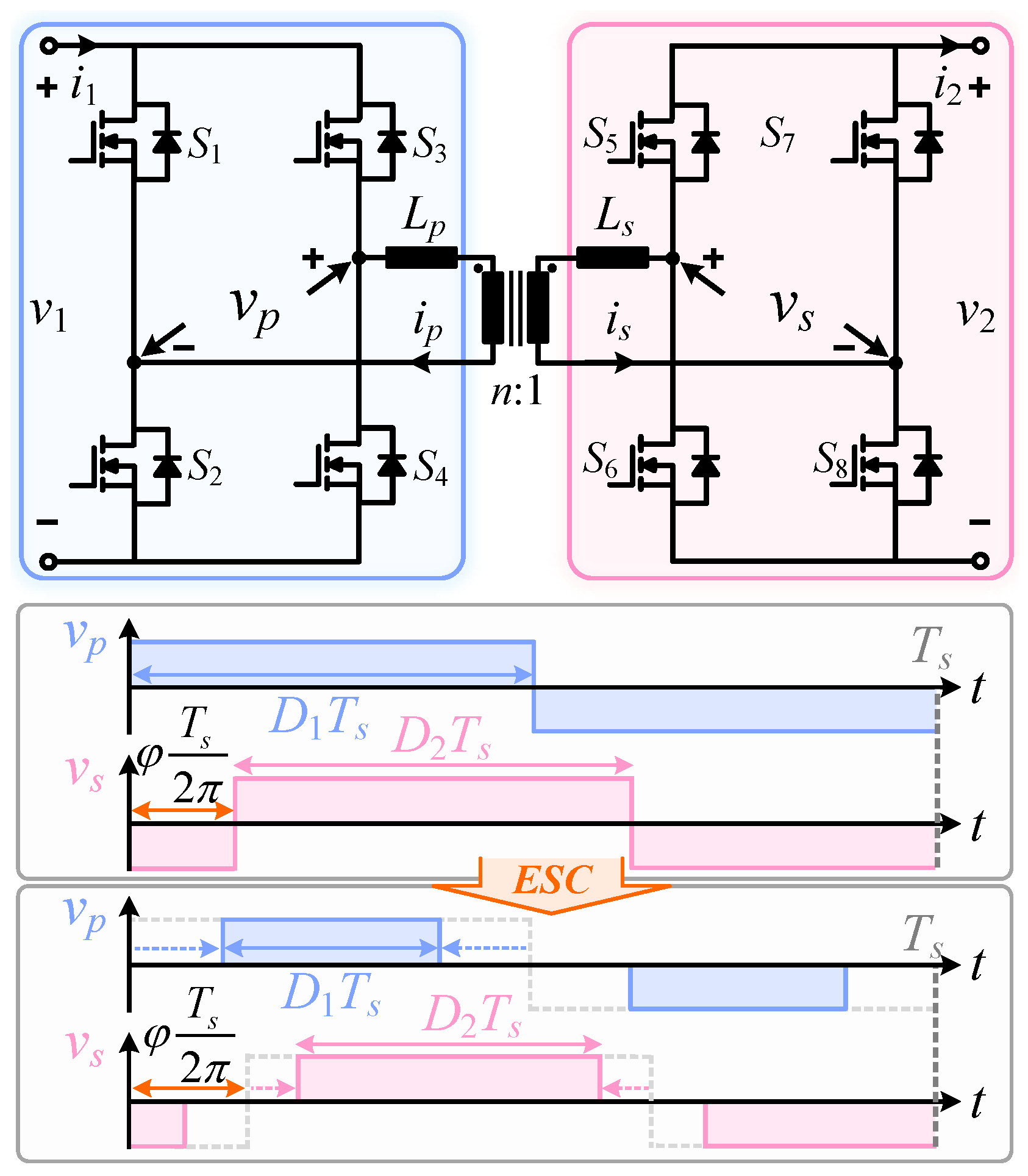
Figure 1 illustrates the application of ESC to generate optimal symmetrical duty cycles and for the DAB converter. Operating online and without requiring analytical or Fourier-domain models, the ESC adjusts the duty cycles [21,22,23] to convert the transformer-port voltages and from two-level to symmetrical three-level waveforms (the duty cycles refer to the positive and negative pulses of and , which have identical widths and can be optimized from 0.5 down to 0), and finally reshape the transformer current . This results in a reduction of the input current (input power), when this is set as the objective function. The reason is that duty-cycle adjustments tend to extend the ZVS region and reduce the transformer RMS current, which correspond to lower switching and conduction losses, thereby improving the converter efficiency [21,22,23].
Figure 1.
DAB converter with symmetrical duty-cycle modulation.
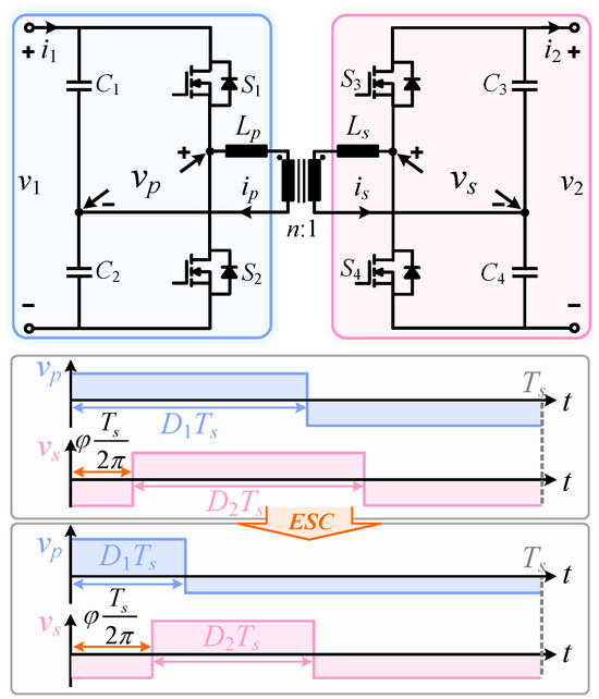
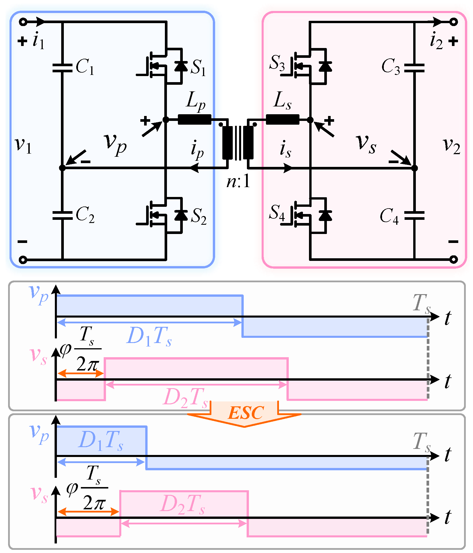
Since DAB and DAHB share very similar operating characteristics and the same number of degrees of freedom, ESC can also be applied to the DAHB converter to determine the optimized duty cycles and . These duty cycles are associated with the positive voltage level durations of the transformer-side voltages and , respectively. In this case, the positive and negative amplitudes of and are asymmetric, as illustrated in Figure 2. Both the transformer current and the transformer-port voltages of the DAHB converter exhibit shape symmetry with respect to duty cycles of 0.5 [33], so that, for example, the operating point is symmetric to . Therefore, this paper focuses only on the case where both and are less than or equal to 0.5.
Figure 2.
DAHB converter with asymmetrical duty-cycle modulation.
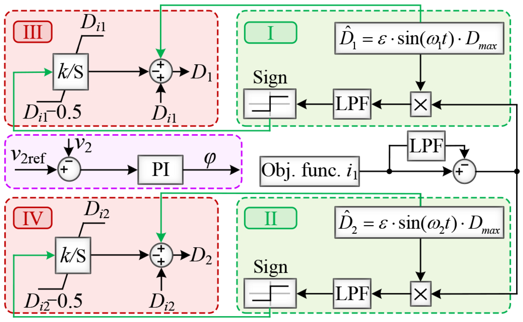
The ESC structure shown in Figure 3 is suitable for dual-bridge converters. While optimizing the duty cycles, a PI controller is used to regulate the power transferred by both DAB and DAHB converters. This process can be interpreted as an online extremum optimization problem with a single constraint; if the constraint is not satisfied, the optimization result becomes invalid. Specifically, effective duty-cycle optimization with the objective of minimizing the input current can only be achieved when the output-voltage control loop successfully regulates the output voltage to track its reference when a resistive load is connected. Without the normal operation of output-voltage control, the input-current minimization-based duty-cycle optimization becomes invalid, because the minimum input current occurs at zero transferred power, where the input current is zero. Obviously, such an operating point is meaningless from a power conversion perspective.
Figure 3.
Traditional extremum seeking control (ESC) structure.
The violation of the power constraint often occurs under dynamic conditions of the reference power, when the reference transferred power suddenly exceeds the current power transfer capability (the maximum transferable power under the given duty cycles, which is achieved by applying the appropriate phase-shift angle to achieve the maximum power transfer attainable by the DAHB converter under the preset duty cycles), the output-voltage control loop becomes saturated and fails to maintain voltage regulation anymore. Specifically, the explicit expression of the DAHB converter’s , also known as the maximum transferable power under the given duty cycles of and , as given in [33], is as follows:
where the total leakage inductance is given by , is switching frequency (constant), and denote the given DC-port voltages, and represents the upper limit of transferable power of DAHB, which is attained when . It should also be noted that [33] indicates that ; for example, with and leading to , the DAHB converter achieves its . From (1), when and are reduced by the ESC optimization process, the power transfer capability is correspondingly reduced. If the reference power steps above , the achievable output power becomes insufficient to meet the load demand. As a consequence, the output-voltage regulator used to generate the phase-shift angle enters the preset saturation limit (which can be either a fixed value or a duty cycle-dependent value, e.g., ), ultimately leading to output-voltage collapse when a resistive load is connected. Based on the ESC structure, it should be noted that if suddenly increases but remains below , the output-voltage controller increases the phase-shift angle appropriately to enhance the transmitted power, and the output voltage quickly returns to its reference value without driving the PI controller into saturation. However, if rises above , the PI controller output, regardless of further increase, can at most achieve and cannot satisfy . In this case, the output voltage PI controller remains at its preset saturation limit.
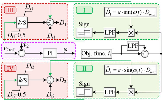
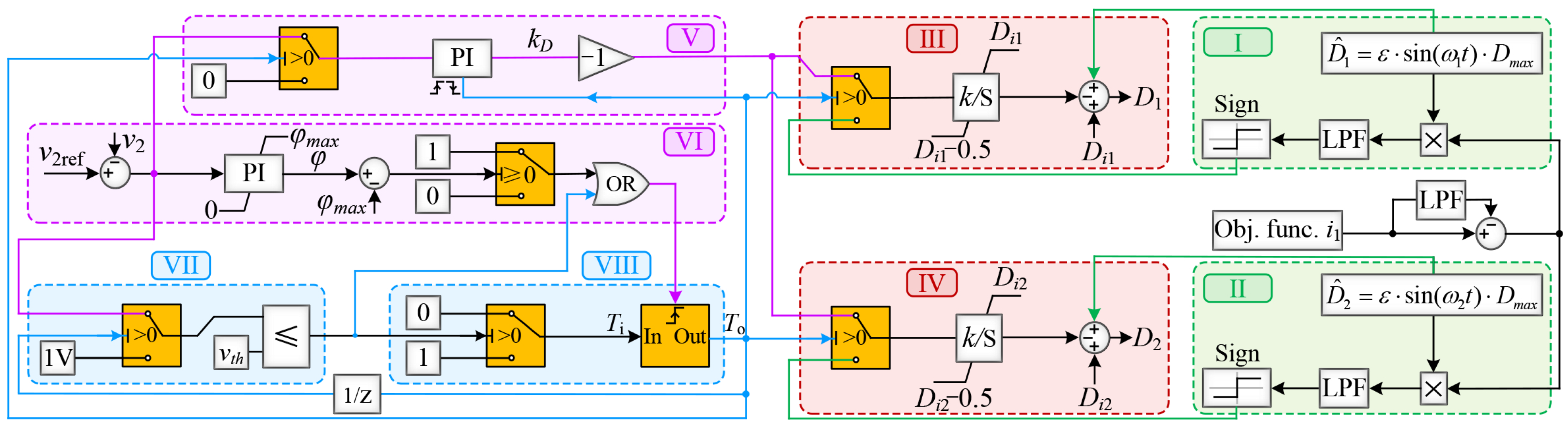
Overall, the fundamental reason for the dynamic collapse of ESC is that, when applied to dual-bridge converters, the optimized duty cycles—although improving converter efficiency—simultaneously reduce the power transfer capability . Consequently, during dynamic events in which suddenly exceeds , the duty cycles continue to adjust slowly with the objective of minimizing the input current and cannot respond to the change in power demand. To address the problem of dynamic collapse caused by the application of conventional ESC in dual-bridge converters when suddenly exceeds , a mechanism is required to rapidly adjust and to quickly increase . Accordingly, the structure of the conventional ESC must be modified, leading to the proposed enhanced ESC (EESC), as shown in Figure 4.
Figure 4.
Proposed enhanced extremum seeking control (EESC) structure.
3. Mechanism of the Proposed EESC Structure
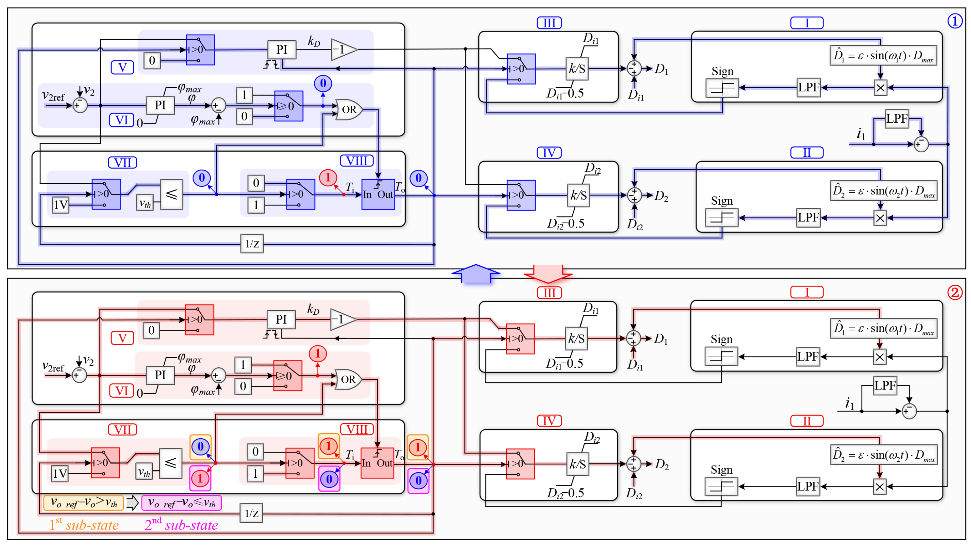
The proposed EESC structure not only incorporates a conventional ESC-based duty-cycle optimization loop with small-amplitude sinusoidal perturbations, enabling a slow optimization of the duty cycles to minimize the objective function (e.g., the input current ) and thus maximize converter operating efficiency, but it also allows rapid adjustment in the duty cycles to promptly increase the power transfer capability. These two components, responsible for the slow variation and rapid increase in the duty cycles, are coordinated through multiple switching conditions and logical selectors, resulting in eight functional blocks labeled from I to VIII. Among them, only the sinusoidal duty-cycle injection blocks (I and II) and the integral parts together with the duty-cycle summation parts of blocks III and IV are retained from the conventional ESC, as shown in Figure 3 and Figure 4.
- Blocks I and II: In these blocks, small-amplitude perturbations with identical magnitudes but different frequencies are injected into the duty cycles. Based on the resulting objective function (input current ) response, the duty-cycle adjustments required to achieve the objective function minimization objective are generated and superimposed onto the initial duty cycles and . Accordingly, the optimization procedures implemented in these blocks, define the primary- and secondary-side duty cycles, and , as perwhere represents the initial conditions, k denotes the integral gain of the duty cycles, and is the cutoff frequency of the low-pass filters (LPFs) employed to compute the averaged values of objective function (input current ) and the ESC correlation terms [21]. In addition, (3) accounts for the duty-cycle perturbations and , defined as follows:where denotes the magnitude of the injected duty-cycle perturbation, while and represent the angular frequencies of the injected perturbations. The former is typically kept small to prevent the transformer current and transferred power from exhibiting relatively large fluctuations, undesirable from the load perspective. Therefore, in this study, this value is chosen as of . The latter, to ensure proper operation, are set higher than the cutoff frequency of the low-pass filters. Also, all low-pass filters are set with the same cutoff frequency; otherwise, the EESC may fail to converge to the correct high-efficiency operating point [22].
- Blocks III and IV: These two blocks are responsible for selecting the operation mode, choosing either the perturbation-based, slowly optimized duty cycles from block I with block II, or the fast-rising non-optimized duty cycles from block V according to the output of the trigger system in Block VIII (i.e., ).
- Block V: This block contains a PI regulator that generates the coefficient , which is multiplied by the integrator gain k in Blocks III and IV. The PI regulator in Block V is not continuously active; it is enabled only when a high level trigger signal is issued by Block VIII (i.e., ). When the regulator is disabled, it is reset and its output is forced to zero. Only when the regulator is enabled does its input correspond to the error between the output voltage and its reference.
- Block VI: A PI-based phase-shift angle regulator continuously processes the output-voltage error and determines the phase-shift angle . The regulator output is limited and clamped by a predefined threshold . The difference between the regulator output and is then compared with zero (i.e., whether ) and used as the decision condition of a threshold-controlled switch. The output of this threshold-controlled switch, together with the output of Block VII, forms a trigger signal for Block VII through a logical OR operation.
- Block VII: This block consists of a threshold-controlled switch cascaded with a comparator. The signal (i.e., ) from the trigger system in block VIII determines whether the output is the voltage error or a specific value exceeding (e.g., 1 V), with (i.e., whether or ). Once the threshold is reached, the output of the switch is compared with , and the comparison result—either 0 or 1—is sent to block VI and block VIII.
- Block VIII: This part contains a threshold-controlled switch, which essentially inverts the signal sent from block VII. When block VII sends a high-level signal (1), the threshold-controlled switch outputs a low-level signal (0). This output serves as the input to trigger the trigger system (i.e., ), and together with the driving signal from block VI, it determines the resulting high- or low-level output (i.e., ).
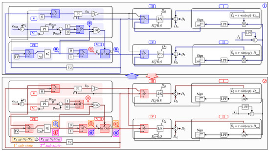
The detailed operating sequence of the proposed EESC including the blocks in the Figure 4 is illustrated in Figure 5. Overall, it can be divided into two main states, ➀ and ➁, where the second main state ➁ further consists of two sub-states.
Figure 5.
Operating sequence of the proposed enhanced extremum seeking control (EESC) structure.
In the main state ➀, the blue lines represent the signal transmission paths. It can be observed that the perturbation duty cycles are injected to activate the objective function-optimization (input-current optimization, which corresponds to the efficiency optimization) mode through block I, block II, block III, and block IV. Meanwhile, the output voltage PI controller in block VI operates in the normal (unsaturated) state. Since is smaller than zero, the output of block VI remains at a low logic level (0). In addition, the output of block VII is also a low logic level (0), such that the trigger system in block VIII is not activated (i.e., ). Consequently, the values generated by the sign function in block I and block II, multiplied by the gain k, are applied as the duty-cycle variation slopes for block III and block IV.
Regarding the main state ➁, illustrated by the red lines in Figure 5, when the load demand increases such that the phase-shift angle reaches its saturation limit , the trigger system in block VIII is activated upon receiving a high-level signal from block VI. The trigger system activation results in the outputs of the switches in block III and block IV being determined by the product of the PI controller output from block V and the gain k in block III and block IV. As a consequence, the duty cycles and are increased from their initial optimized values and to enhance the power transfer capability , i.e.,
where the applied duty cycles rapidly increase from the lower values and to the higher values and as long as , which defines the first sub-state (here, is set to 0). Once (defined as the second sub-state), the output of block VII changes from low (0) to high (1), while the input of the trigger system (i.e., ) in block IV switches from high (1) to low (0). Since the trigger system remains active throughout state ➁, its output transitions from 1 to 0. Overall, the input–output behavior of the trigger system, together with its trigger signal, denoted by and , is summarized as
Notably, the output of the trigger system in block VIII must first pass through a one-step delay before reaching the threshold input of the switch in block VII; omitting this delay would cause the control loop to lock up. Therefore, after this one-step delay, main state ➁ is completed and the system transitions to main state ➀.
It should be noted that the proposed EESC structure is not limited to DAHB converters and can also be applied to DAB converters. This is because both the DAHB and DAB converters transfer power through the phase-shift angle between the transformer port voltages, which serves as a degree of freedom for power transfer and results in same power transfer characteristics. In addition, both converters possess two additional degrees of freedom, namely the duty cycles and on the primary and secondary sides. For both converters, the duty cycles are adjusted to optimize the converter efficiency accompanied by a change in the power transfer capability , as illustrated in Figure 1 and Figure 2. Specifically, the maximum duty cycle for both converters is 0.5, and efficiency optimization is achieved by reducing the duty cycle from 0.5. Increasing the duty cycle from values lower than 0.5 leads to an increase in , indicating that both converters exhibit the same optimization trend.
The proposed EESC is specifically designed for dual-bridge converters because optimizing the duty cycles in these converters reduces the power transfer capability . During dynamic load changes, this can lead to situations where the reference power exceeds , causing conventional ESC to fail and the output voltage to collapse. The proposed EESC addresses this issue by rapidly adjusting the duty cycles to restore and maintain stable power transfer. For instance, in photovoltaic applications using Boost converter, the reference power typically does not exceed the available power transfer capability. In such cases, conventional ESC suffices, and output-voltage collapse does not occur. Although EESC is specifically tailored for dual-bridge converters, these converters are widely used in both DC and AC grids, making the proposed strategy highly relevant and valuable.
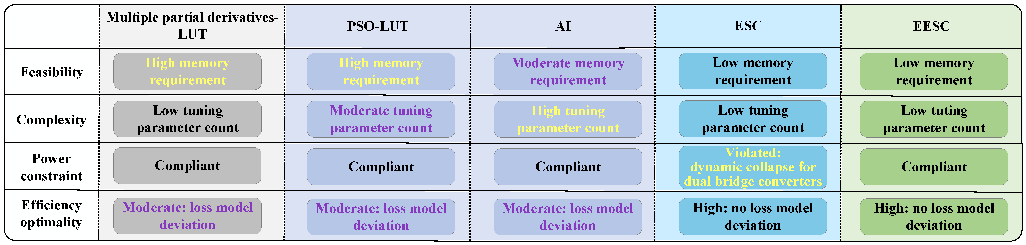
After describing the EESC structure, it is compared with several representative methods from the Introduction, as shown in Figure 6. Feasibility, critical for common controller like DSP implementation, is limited by memory as follows: multiple partial-derivative and PSO methods require offline computation of optimized duty cycles stored in lookup tables, while AI-based methods need numerous parameters depending on layers and neurons, more than ESC and EESC. In terms of complexity, multiple partial-derivative, ESC, and EESC are non-intelligent algorithms with few tuning parameters, whereas PSO and AI require extensive auto-tuning. Notably, only ESC violates power constraints. For efficiency optimality, multiple partial-derivative and PSO rely on ideal circuit-loss models with estimated parasitics, and AI depends on offline-trained control laws, while ESC and EESC perform online extremum searches independent of circuit-loss models. Overall, EESC is a simple, practical and effective method difficult to replace by other approaches.
Figure 6.
Comprehensive comparison of partial-derivative, PSO-based, AI-based, ESC, and EESC methods in terms of feasibility, complexity, power-constraint compliance, and efficiency optimality.
4. Experimental Results
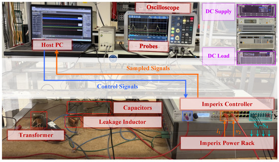
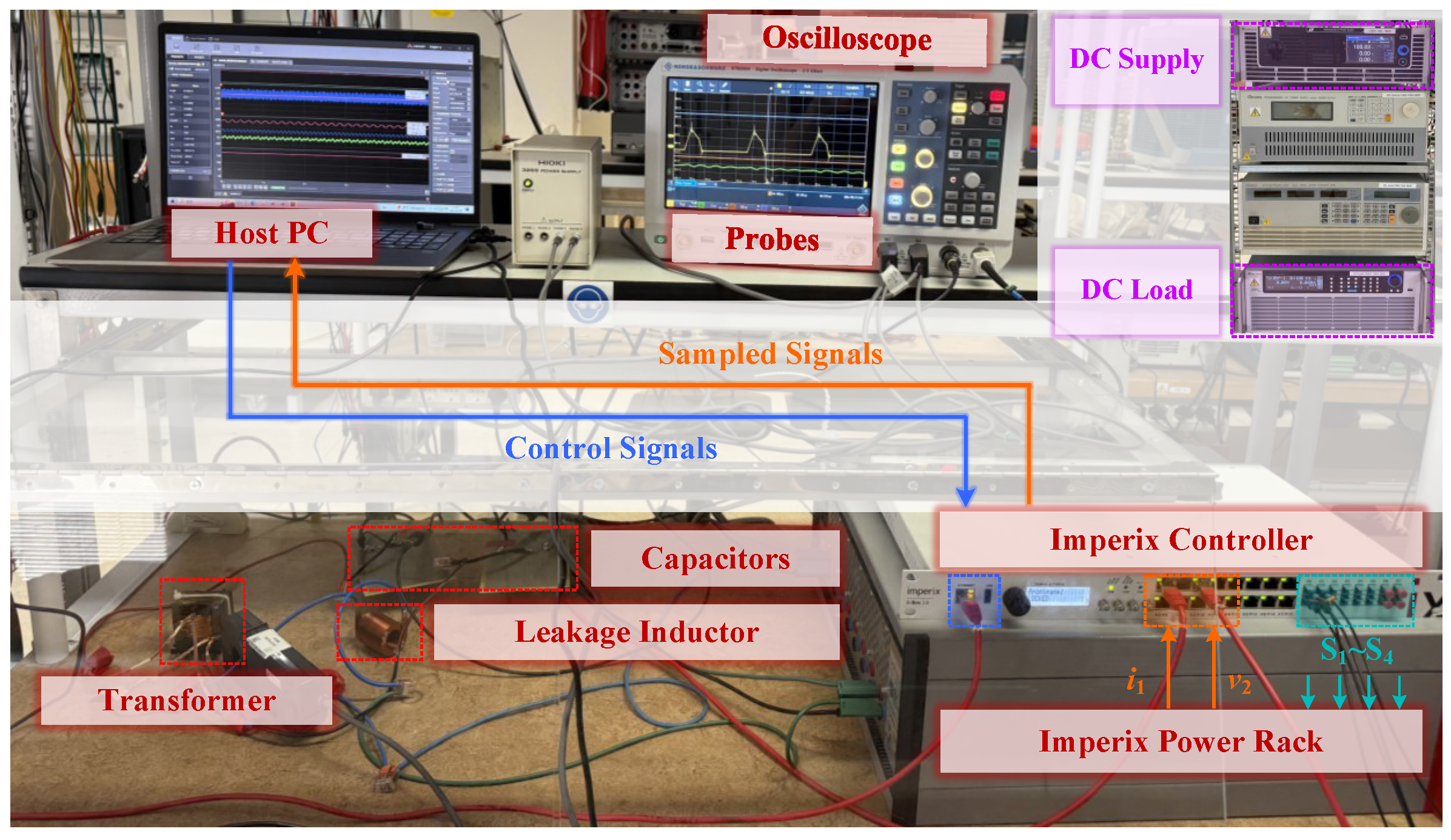
Figure 7 shows the experimental platform using an Imperix Boombox 3.0 controller (Imperix, Sion, Switzerland) to implement both the conventional ESC and the proposed EESC.
Figure 7.
Experimental platform for verifying DAHB operation under ESC and proposed EESC.
The converter is built from an Imperix power rack together with an external transformer, inductor, and split capacitors, forming a DAHB converter as an experimental case, with the specific parameters listed in Table 1. The duty-cycle perturbations and are injected at frequencies of 12 Hz and 18 Hz, respectively, with equal amplitudes of 0.001.
Table 1.
DAHB experimental parameters.
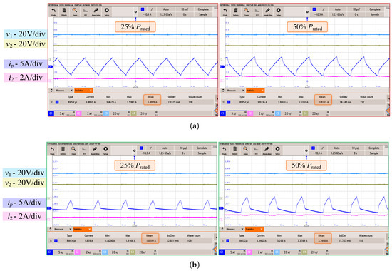
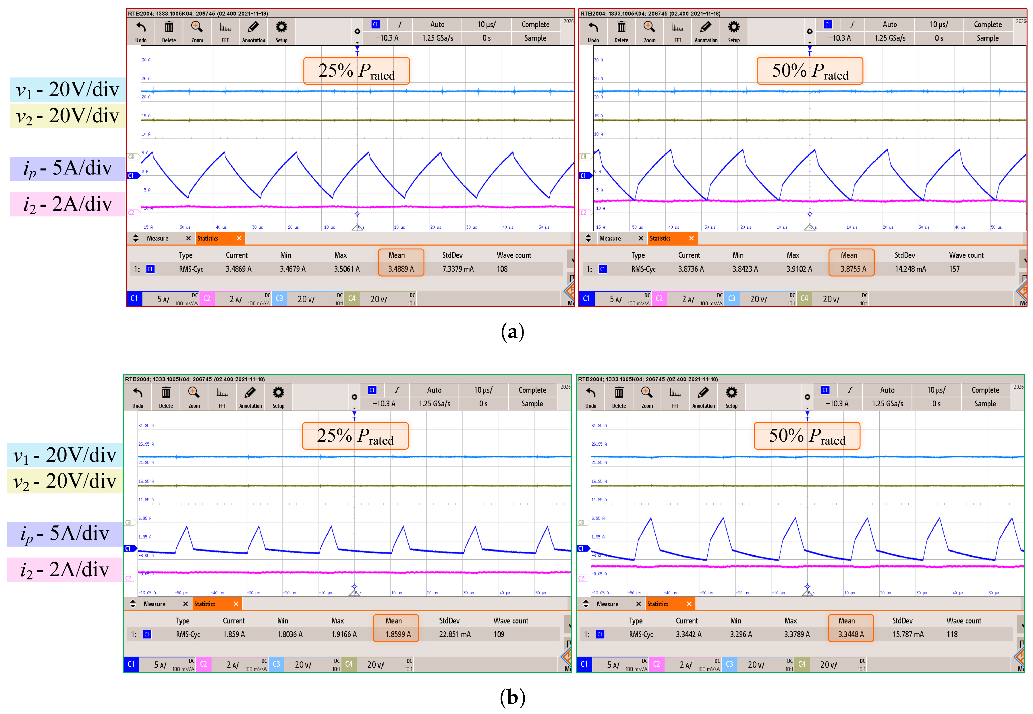
Figure 8 shows the input and output voltages, and , together with the transformer current and the output current , corresponding to the non-optimized and optimized duty cycles and , respectively. In the non-optimized case, both duty cycles are set to 0.5, resulting in transformer RMS currents (which are closely related to conduction losses) of 3.49 A and 3.88 A at 25% and 50% , respectively. Under the same operating conditions, the optimized duty cycles are at 25% and at 50% , leading to reduced transformer RMS currents of 1.86 A and 3.34 A, respectively. As a result, the optimized duty cycles improve the conversion efficiency by 14.67% and 2.06% at 25% and 50% , respectively. This demonstrates that the proposed EESC can effectively optimize the efficiency of the converter.
Figure 8.
Comparison of waveforms at 25% and 50% of : (a) with non-optimized duty-cycles; (b) with duty cycles optimized by the EESC.
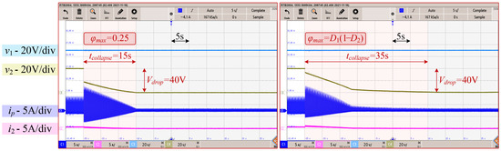
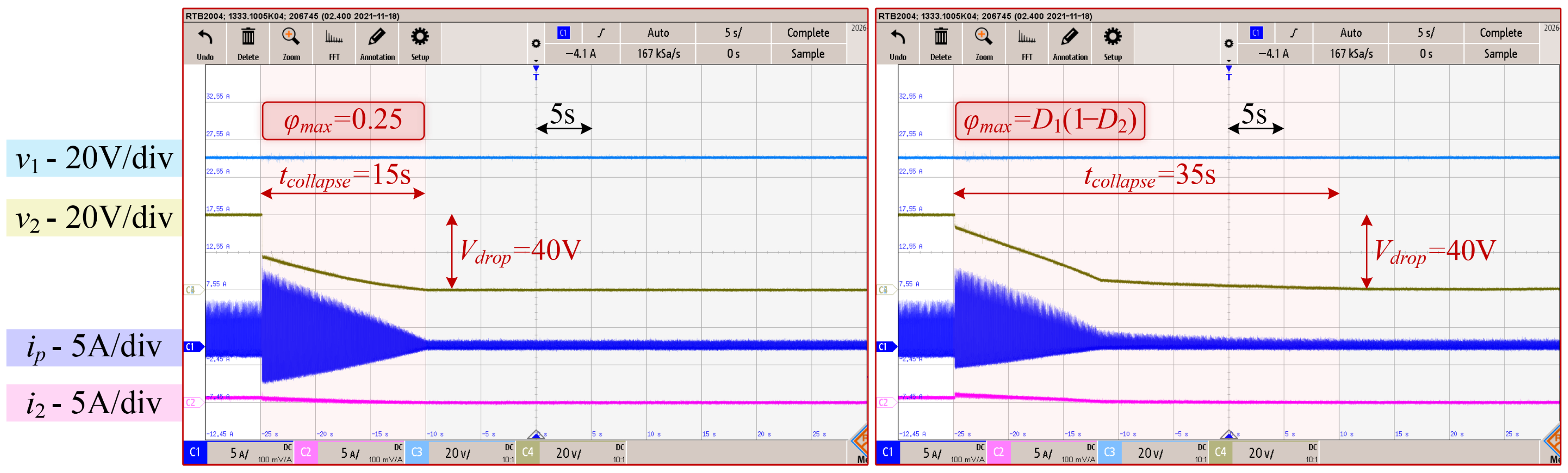
Figure 9 shows the voltage collapse phenomenon caused by conventional ESC. Regardless of whether is set to the commonly used value of 0.25 (i.e., 90°) or determined according to the duty cycles as , the output voltage still experiences a sudden drop and gradually collapses to 0 V. In the case of , the maximum transferable power (i.e., ) can be maintained with the variation of the duty cycles, which delays the collapse time to about 35 s compared with 15 s when . However, since the available power transfer capability is still lower than the reference power , the load demand cannot be satisfied and the output voltage ultimately collapses.
Figure 9.
Full process of voltage collapse in the DAHB converter with ESC under different limitations of phase-shift angles during a load step from 25% to 50% of .
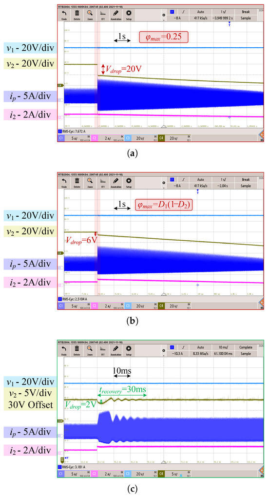
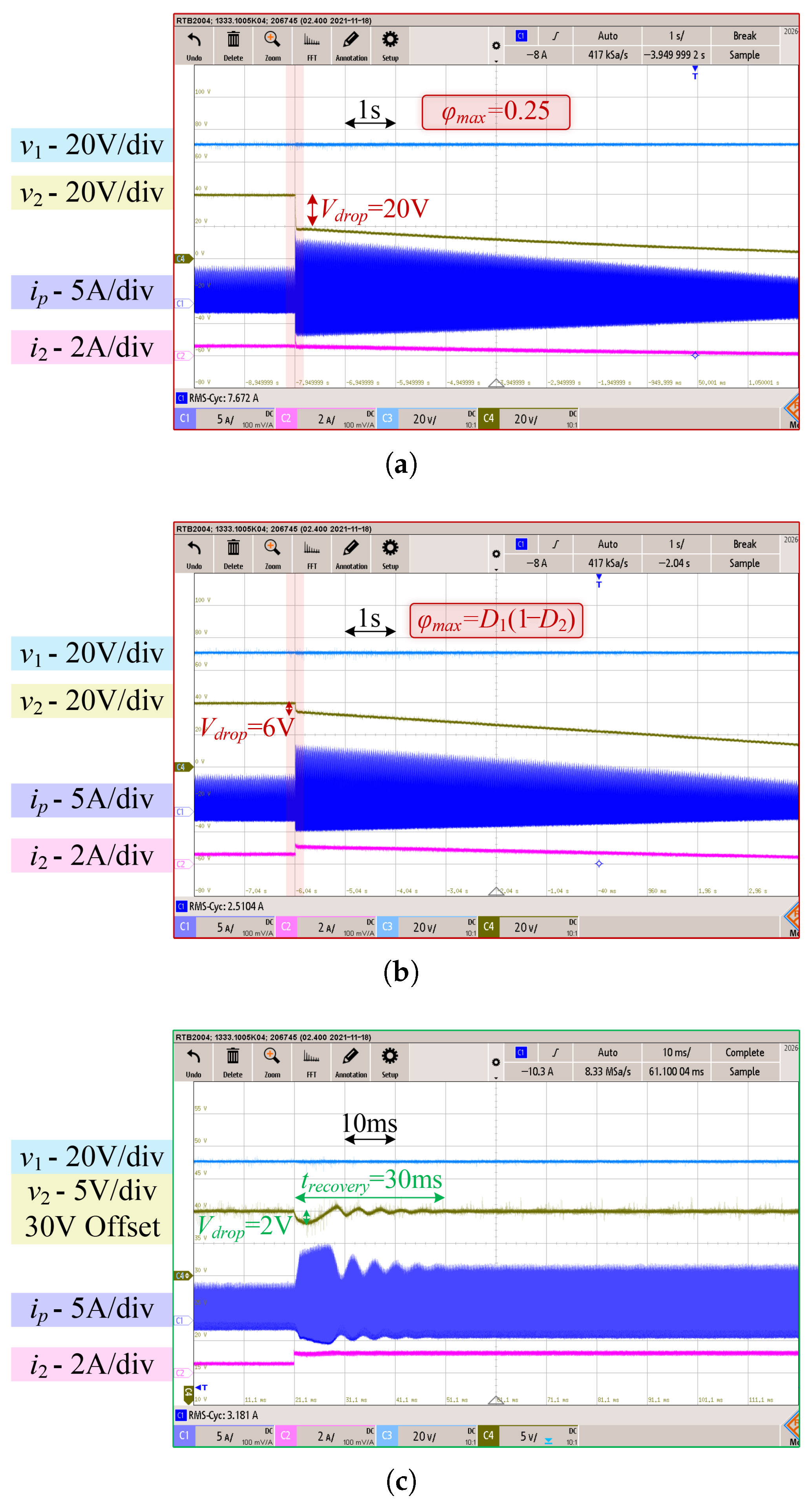
Figure 10 shows the dynamic comparison of the DAHB converter during a load step from 25% to 50% under ESC and EESC. For a fair comparison, the ESC is conducted with a fixed phase-shift angle saturation as Figure 10a and a time-varying phase-shift angle saturation according to as Figure 10b. It can be clearly observed that, when using the traditional ESC, whether the phase-shift angle saturation is fixed or varies with duty cycles, the output voltage drops suddenly by nearly 20 V and 6 V immediately after the load step and then remains far below , collapsing gradually.
Figure 10.
Dynamic comparison of the DAHB converter under a load step from 25% to 50% : (a) based on the traditional ESC with fixed phase shift angle saturation; (b) based on the traditional ESC with time-varying phase-shift-angle saturation; (c) based on the proposed EESC.
In contrast, when using the proposed EESC, as shown in Figure 10c, the output voltage experiences a maximum deviation of only 2 V at the instant of the load step and reaches steady state within approximately 30 ms. No voltage collapse occurs, demonstrating that the traditional ESC suffers from power transfer limitations and voltage collapse issues, whereas the EESC effectively avoids such problems.
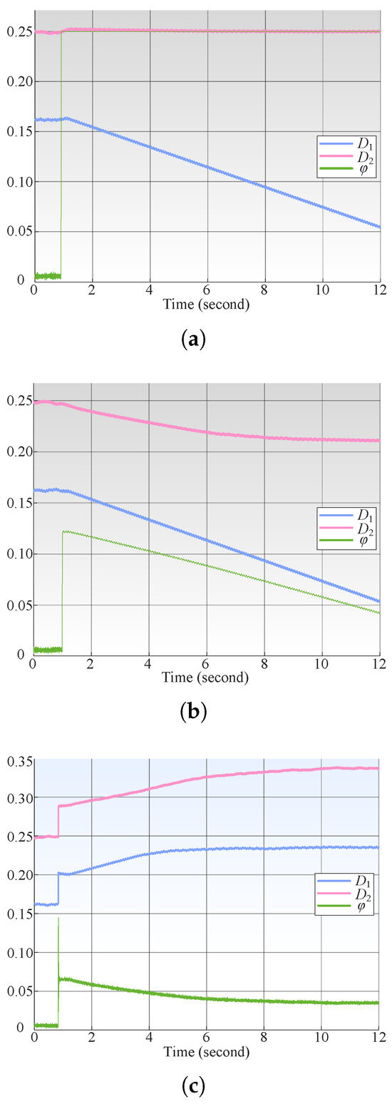
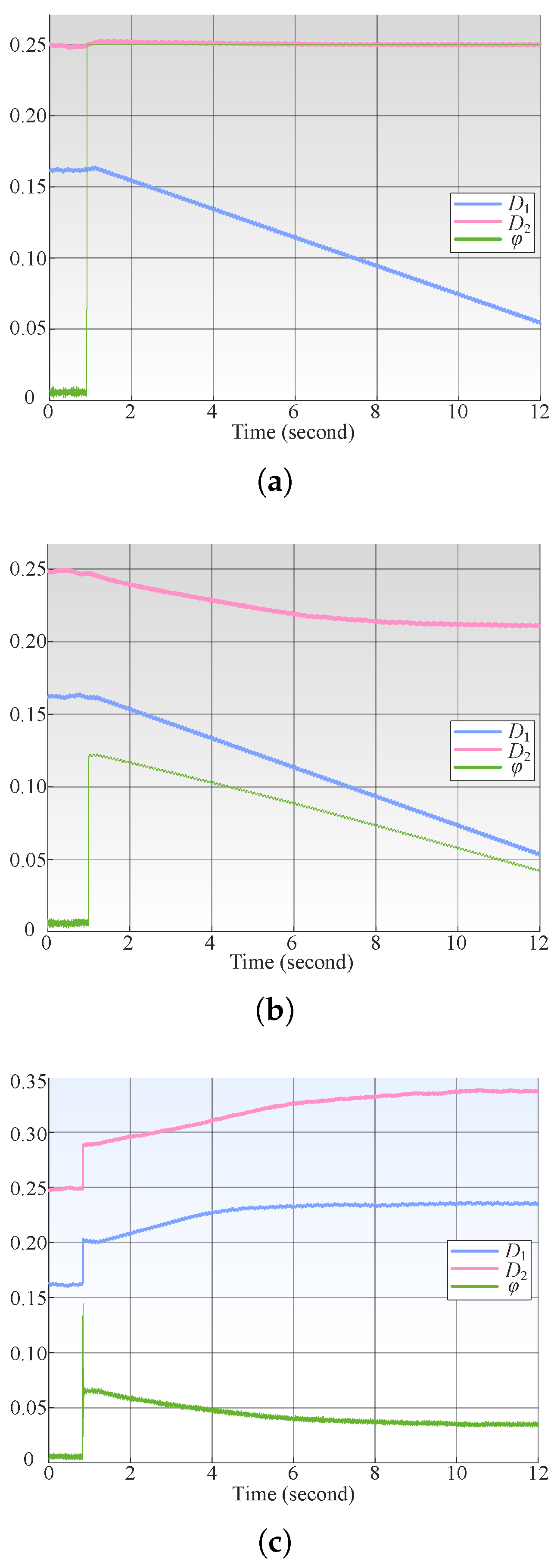
Figure 11 shows the evolution of the control parameters , , and , as recorded by the control monitoring system, during a load step, corresponding to the experimental plots in Figure 10 (same order). Before the load step, both the traditional ESC and the proposed EESC maintain , , and at the appropriate steady-state values. However, when the load step occurs, the duty cycles prior to the step result in a power transfer capability that is insufficient to meet the load requirement. In this case, under the traditional ESC with both fixed and time-varying phase-shift angle saturation limits as shown in Figure 11a, immediately saturates at its limit, and remains nearly constant under fixed phase-shift angle saturation, whereas decreases initially and then remains constant under time-varying phase-shift angle saturation as Figure 11b, and all decreases continuously. This behavior is due to the lack of power constraint as follows: the ESC still attempts to adjust and to minimize the input current . As decreases (further limiting the power transfer), naturally decreases as well, rendering the adjustment meaningless.
Figure 11.
Trends of , , and during a load step from 25% to 50% : (a) based on the traditional ESC with fixed phase-shift angle saturation; (b) based on the traditional ESC with time-varying phase-shift angle saturation; and (c) based on the proposed EESC.
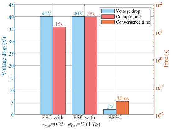
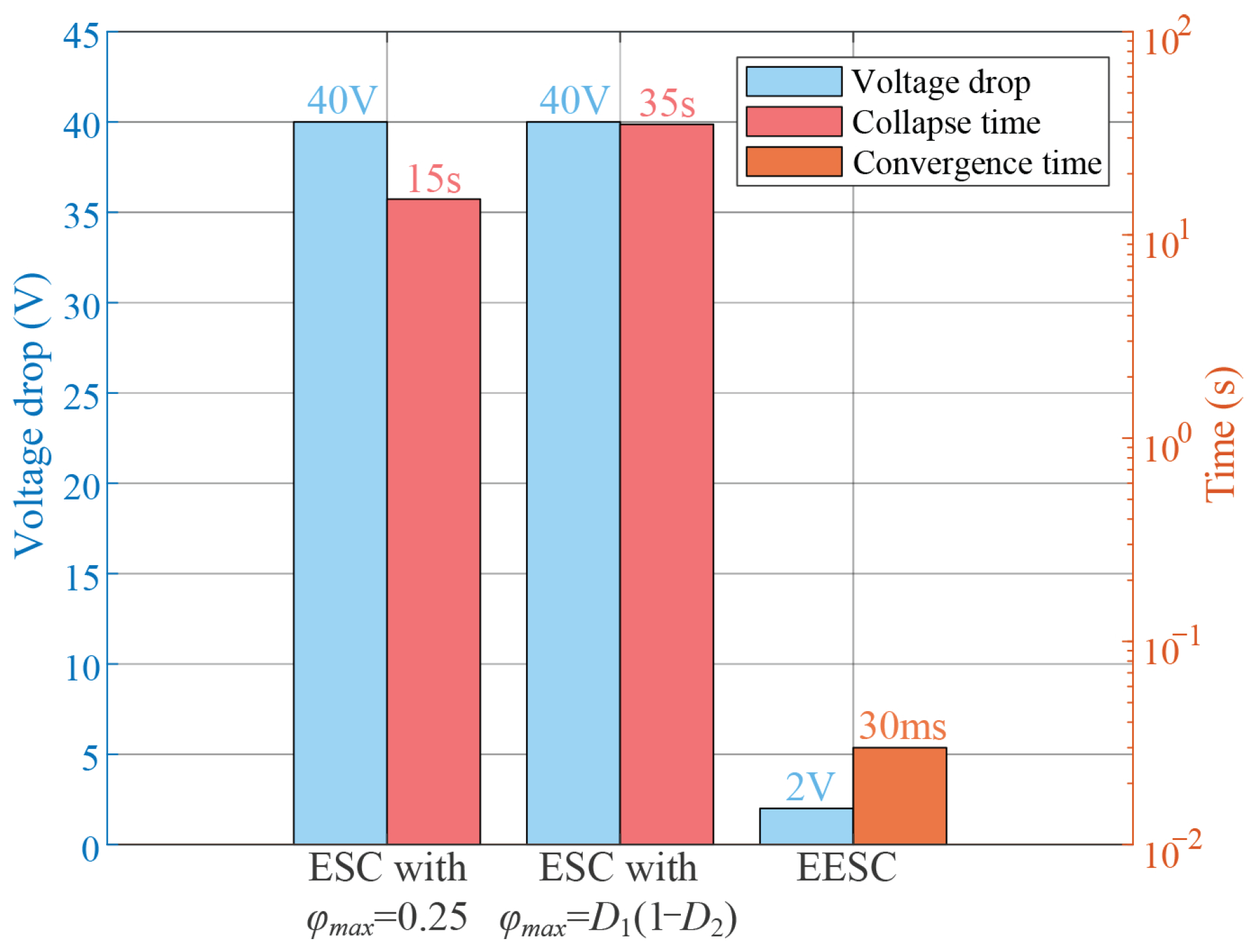
By contrast, Figure 11c shows the performance under EESC, where the proposed strategy suspends the slow optimization of during the load step, and both and are rapidly increased to enhance the converter’s power transfer capability. Once and reach values that bring the output voltage close to , the slow optimization targeting input-current minimization resumes. Meanwhile, does not remain saturated as in the traditional ESC. Figure 12 summarizes the performance comparison of ESC with different phase-shift angle limitations and proposed EESC. The ESC exhibits a voltage drop of 40 V, with the output voltage fully collapsing to 0 V and collapse times of 15 s and 35 s, while the EESC shows a much smaller voltage drop of only 2 V and a convergence time of 30 ms. This demonstrates the significant performance improvement of the EESC compared to the ESCs.
Figure 12.
Comparison of voltage drop and time response for ESC with fixed phase-shift angle saturation, ESC with duty cycle-dependent phase-shift angle saturation, and EESC under a load step from 25% to 50% (blue bars: voltage drop; red bars: collapse time; and light orange bar indicates EESC convergence time).
5. Conclusions
This paper has two main contributions as follows: first, it reveals for the first time the phenomenon and underlying causes of dynamic output-voltage collapse encountered by conventional extremum seeking control (ESC) in dual-bridge converters under load transient conditions, and it proposes, for the first time, an enhanced extremum seeking control (EESC) strategy to overcome this collapse. Specifically, the ESC structure causes output-voltage collapse because the optimized duty cycle reduces the converter’s power transfer capability, leading to collapse when the reference power suddenly exceeds this capability. The proposed EESC structure integrates the following two complementary mechanisms: a slow duty-cycle optimization aimed at minimizing the input current to improve converter efficiency, and a fast duty-cycle adjustment that rapidly responds to load transients by enhancing the power transfer capability. Comparative experimental results using a 105 W-rated DAHB converter connected to a purely resistive load—implying that the output voltage and current follow identical trends—validate that the conventional ESC suffers from output-voltage collapse from 40 V to 0 V, which also corresponds to the output current dropping to 0 A, when the load increases from 25% to 50% of the rated power due to power transfer limitations. In contrast, the proposed EESC not only eliminates output-voltage collapse, exhibiting a maximum voltage drop of only 2 V relative to the reference output that fully recovers within 30 ms during transient conditions, but it also preserves efficiency optimization, achieving a 14.67% efficiency improvement at 25% of rated power and a 2.06% improvement at 50% of rated power compared with the case where duty cycles are not optimized and are all set to 0.5.
Author Contributions
Conceptualization, Z.W., P.S., P.M., and S.B.; Methodology, Z.W., P.S., and S.B.; Formal analysis, Z.W., P.S., and S.B.; Investigation, Z.W., P.S., and P.M.; Resources, P.M. and S.B.; Software, Z.W.; Validation, Z.W. and P.S.; Visualization, Z.W.; Writing—original draft, Z.W.; Writing—review and editing, P.S., P.M., and S.B. All authors have read and agreed to the published version of the manuscript.
Funding
This research received no external funding.
Data Availability Statement
All data supporting the findings of this study are included in the manuscript. Upon request, additional related data can be made available to the reviewers, the journal, and the publisher.
Conflicts of Interest
The authors declare no conflicts of interest.
Abbreviations
The following abbreviations are used in this manuscript:
| DAB | Dual active bridge converter |
| DAHB | Dual active half-bridge converter |
| ESC | Extremum seeking control |
| EESC | Enhanced extremum seeking control |
| RMS | Root mean square |
References
- Amin, S.; Lee, H.-H.; Choi, W. A Novel Power Decoupling Control Method to Eliminate the Double Line Frequency Ripple of Two Stage Single-Phase DC-AC Power Conversion Systems. Electronics 2020, 9, 931. [Google Scholar] [CrossRef] [Scilit]
- Pannawan, A.; Kaewchum, T.; Saeseiw, C.; Pachanapan, P.; Hinkkanen, M.; Somkun, S. Design and Implementation of Single-Phase Grid-Connected Low-Voltage Battery Inverter for Residential Applications. Electronics 2024, 13, 1014. [Google Scholar] [CrossRef] [Scilit]
- Lee, J.-Y.; Kim, H.-S.; Jung, J.-H. Enhanced Dual-Active-Bridge DC–DC Converter for Balancing Bipolar Voltage Level of DC Distribution System. IEEE Trans. Ind. Electron. 2020, 67, 10399–10409. [Google Scholar] [CrossRef] [Scilit]
- He, J.; Chen, Y.; Lin, J.; Chen, J.; Cheng, L.; Wang, Y. Review of Modeling, Modulation, and Control Strategies for the Dual-Active-Bridge DC/DC Converter. Energies 2023, 16, 6646. [Google Scholar] [CrossRef] [Scilit]
- Xu, W.; Guo, Z.; Tayebi, S.M.; Rajendran, S.; Sun, A.; Yu, R.; Hu, Y. Hardware Design and Demonstration of a 100 kW, 99% Efficiency Dual Active Half-Bridge Converter. In Proceedings of the 2020 IEEE Applied Power Electronics Conference and Exposition (APEC), New Orleans, LA, USA, 15–19 March 2020; pp. 1367–1373. [Google Scholar] [CrossRef] [Scilit]
- Zhao, C.; Round, S.D.; Kolar, J.W. An Isolated Three-Port Bidirectional DC–DC Converter with Decoupled Power Flow Management. IEEE Trans. Power Electron. 2008, 23, 2443–2453. [Google Scholar] [CrossRef] [Scilit]
- Chakraborty, S.; Chattopadhyay, S. Minimum-RMS-Current Operation of Asymmetric Dual Active Half-Bridge Converters with and without ZVS. IEEE Trans. Power Electron. 2017, 32, 5132–5145. [Google Scholar] [CrossRef] [Scilit]
- Wu, Z.; Sbabo, P.; Ibrahim, A.; Mattavelli, P.; Buso, S. Enhanced Extremum Seeking Control (EESC) for DAHB DC-DC Converters. In Proceedings of the 2025 IEEE 3rd International Power Electronics and Application Symposium (PEAS), Shenzhen, China, 11–13 June 2025; pp. 229–234. [Google Scholar] [CrossRef] [Scilit]
- Ertekin, D.; Özden, M. Adaptive Neuro Fuzzy Control of a High Gain Bidirectional Power Converter for Photovoltaic-Hydrogen Renewable Electric Vehicles with Enhanced Lifespan and Reliability. Aeu Int. J. Electron. Commun. 2026, 206, 156198. [Google Scholar] [CrossRef] [Scilit]
- Qi, Q.; Ghaderi, D.; Guerrero, J.M. Sliding Mode Controller-Based Switched-Capacitor-Based High DC Gain and Low Voltage Stress DC-DC Boost Converter for Photovoltaic Applications. Int. J. Electr. Power Energy Syst. 2021, 125, 106496. [Google Scholar] [CrossRef] [Scilit]
- Tian, J.; Zhuo, C.; Wang, F.; Deng, H. An RMS Current Minimization Method for Three-Level ANPC-DAB-Based Distributed Energy Storage System with Full-Operation ZVS. IEEE J. Emerg. Sel. Top. Power Electron. 2024, 12, 2388–2405. [Google Scholar] [CrossRef] [Scilit]
- Tian, J.; Zhuo, C.; Wang, F.; Deng, H. Dual-Side Asymmetric Duty Modulation Based on Accurate Soft-Switching Characteristics Modeling for DAB-Based DC Microgrids. IEEE J. Emerg. Sel. Top. Power Electron. 2024, 12, 3146–3160. [Google Scholar] [CrossRef] [Scilit]
- Cao, H.; Lin, N.; Darvish, P.; Yang, Y.; Wang, Z.; Zhao, Y. Enhanced Triple Phase Shift Modulation Strategy for ANPC-DAB Converter to Extend Soft-Switching Range. In Proceedings of the 2024 IEEE Applied Power Electronics Conference and Exposition (APEC), Long Beach, CA, USA, 25–29 February 2024; pp. 445–452. [Google Scholar] [CrossRef] [Scilit]
- Dey, S.; Mallik, A. Multivariable-Modulation-Based Conduction Loss Minimization in a Triple-Active-Bridge Converter. IEEE Trans. Power Electron. 2022, 37, 6599–6612. [Google Scholar] [CrossRef] [Scilit]
- Mou, C.D.; Yuan, L.; Li, J.; Hou, N.; Li, J.; Li, Y.; Zhao, Z. Modeling and Analysis of Hybrid Dual Active Bridge Converter to Optimize Efficiency over the Whole Operating Range. IEEE J. Emerg. Sel. Top. Power Electron. 2023, 11, 432–441. [Google Scholar] [CrossRef] [Scilit]
- Jean-Pierre, G.; Altin, N.; El Shafei, A.; Nasiri, A. Overall Efficiency Improvement of a Dual Active Bridge Converter Based on Triple Phase-Shift Control. Energies 2022, 15, 6933. [Google Scholar] [CrossRef] [Scilit]
- Younis, T.; Al-Ismail, F.S.; Amrr, S.M.; Hussain, S.M.S. Optimization Strategies for Triple-Phase-Shift Modulation in Dual-Active-Bridge Converters: A Comprehensive Review. IEEE Access 2025, 13, 152748–152761. [Google Scholar] [CrossRef] [Scilit]
- Feng, Z.; Wen, H.; Han, X.; Bu, Q.; Zhu, Y.; Wang, G. Deep Reinforcement Learning Assisted Hybrid Five-Variable Modulation Scheme for DAB Converters to Reduce RMS Current and Expand ZVS Operation. IEEE Trans. Power Electron. 2024, 39, 8114–8128. [Google Scholar] [CrossRef] [Scilit]
- Younis, T.; Al-Ismail, F.S.; Hussain, S.M.S. Artificial-Neural-Network Optimized Triple-Active-Bridge Converter Minimizing Total Semiconductor Losses. In Proceedings of the IECON 2025—51st Annual Conference of the IEEE Industrial Electronics Society, Madrid, Spain, 14–17 October 2025; pp. 1–6. [Google Scholar] [CrossRef] [Scilit]
- Özden, M.; Ertekin, D.; Siano, P. Levenberg–Marquardt Algorithm-Based Neural Network Smart Control Strategy for a Low-Input Current Ripple and High-Voltage Gain Power Converter in Fuel-Cells Energy Systems. IEEE Access 2025, 13, 3613–3631. [Google Scholar] [CrossRef] [Scilit]
- Ibrahim, A.A.; Caldognetto, T.; Biadene, D.; Mattavelli, P. Multidimensional ripple correlation technique for optimal operation of triple-active-bridge converters. IEEE Trans. Ind. Electron. 2023, 70, 8032–8041. [Google Scholar] [CrossRef] [Scilit]
- Ibrahim, A.A.; Caldognetto, T.; Biadene, D.; Mattavelli, P. Model-Free Online 4-D Ripple Correlation Control for Loss Optimization of Isolated Quad-Active Bridge Converters. IEEE Trans. Transp. Electrif. 2024, 10, 10328–10337. [Google Scholar] [CrossRef] [Scilit]
- Ibrahim, A.A.; Darisi, M.; Caldognetto, T.; Biadene, D.; Magnone, P.; Mattavelli, P. EMI-Silent Operation of Triple Active Bridge Converters with Online Model-Free ZVS Optimization and RMS Current Reduction. IEEE Open J. Ind. Appl. 2025, 6, 249–261. [Google Scholar] [CrossRef] [Scilit]
- Esram, T.; Kimball, J.W.; Krein, P.T.; Chapman, P.L.; Midya, P. Dynamic maximum power point tracking of photovoltaic arrays using ripple correlation control. IEEE Trans. Power Electron. 2006, 21, 1282–1291. [Google Scholar] [CrossRef] [Scilit]
- Bazzi, A.M.; Krein, P.T. Ripple Correlation Control: An Extremum Seeking Control Perspective for Real-Time Optimization. IEEE Trans. Power Electron. 2014, 29, 988–995. [Google Scholar] [CrossRef] [Scilit]
- Barth, C.; Pilawa-Podgurski, R.C.N. Dithering Digital Ripple Correlation Control for Photovoltaic Maximum Power Point Tracking. IEEE Trans. Power Electron. 2015, 30, 4548–4559. [Google Scholar] [CrossRef] [Scilit]
- Khazaee, A.; Yazdani, A.; Mosaddegh Hesar, H.; Wu, B. Efficient MPPT for BLDCM-Driven PV Pumping System Based on Ripple Correlation Control. IEEE Trans. Power Electron. 2023, 38, 8022–8026. [Google Scholar] [CrossRef] [Scilit]
- Khazaee, A.; Yazdani, A.; Makhdoumi, A.; Atashin, S.A.; Wu, B. Loss Minimization Algorithm for Surface-Mounted PMSM Using Ripple-Based Extremum Seeking. IEEE Trans. Ind. Electron. 2024, 71, 15325–15335. [Google Scholar] [CrossRef] [Scilit]
- Zhang, Z.; Wu, X.; Yang, B. Maximum Torque per Ampere Control of IPMSM Based on Current Angle Searching with Sliding-Mode Extremum Seeking. Energies 2025, 18, 5613. [Google Scholar] [CrossRef] [Scilit]
- Zhang, X.; Zhang, Y.; Ning, C.; Chen, S.; Ma, Z. Maximum Torque per Ampere Control for IPMSM Based on Sliding Mode Extremum Seeking Control Without Steady-State Oscillation. IEEE J. Emerg. Sel. Top. Power Electron. 2026, 14, 1203–1214. [Google Scholar] [CrossRef] [Scilit]
- Lin, X.; Liu, J.; Liu, Z.; Gao, Y.; Peretti, L.; Wu, L. Model-Free Current Predictive Control for PMSMs with Ultralocal Model Employing Fixed-Time Observer and Extremum-Seeking Method. IEEE Trans. Power Electron. 2025, 40, 10682–10693. [Google Scholar] [CrossRef] [Scilit]
- Tang, R.; Song, H.; Lin, X.; Jiang, S.; Gao, X.; Liu, Z.; Liu, J. Prescribed-Time Synchronization of Second-Order Kuramoto Oscillators. IEEE Trans. Circuits Syst. II Express Briefs 2026. [Google Scholar] [CrossRef] [Scilit]
- Gao, G.F.; Mugwisi, N.; Rogers, D.J. Average Modeling of a Dual-Half-Bridge Converter Modulated With Three Degrees of Freedom. IEEE Trans. Transp. Electrif. 2021, 7, 1016–1030. [Google Scholar] [CrossRef] [Scilit]


Disclaimer/Publisher’s Note: The statements, opinions and data contained in all publications are solely those of the individual author(s) and contributor(s) and not of MDPI and/or the editor(s). MDPI and/or the editor(s) disclaim responsibility for any injury to people or property resulting from any ideas, methods, instructions or products referred to in the content. |
© 2026 by the authors. Licensee MDPI, Basel, Switzerland. This article is an open access article distributed under the terms and conditions of the Creative Commons Attribution (CC BY) license.