Article

Coordinated Black-Start Control of a Diesel Generator–V2G System for Enhanced Frequency Support

1
Beijing EV Charging and Battery Swapping Engineering Technology Research Center, China Electric Power Research Institute Co., Ltd., Beijing 100192, China
2
Energy Utilization Research Institute, China Electric Power Research Institute Co., Ltd., Beijing 100192, China
3
Anhui Provincial Key Laboratory of New Energy Utilization and Energy Conservation, Hefei University of Technology, Hefei 230009, China
*
Author to whom correspondence should be addressed.
Electronics 2026, 15(19), 4563; https://doi.org/10.3390/electronics15194563
Submission received: 28 August 2026 / Revised: 29 September 2026 / Accepted: 3 October 2026 / Published: 8 October 2026
(This article belongs to the Special Issue Decentralized Control Strategies for Multi-Microgrid Systems)

Abstract

To address the limitations of conventional black-start sources associated with geographical constraints and capacity configuration, a coordinated black-start control method was proposed for an islanded auxiliary-power microgrid of a biomass combined heat and power (CHP) plant, in which a diesel generator and a vehicle-to-grid (V2G) cluster operate cooperatively. First, a dynamic available-capacity assessment model was established for the V2G cluster. The diesel-generator capacity was then verified by considering the startup impacts of plant auxiliary motors, and the corresponding black-start restoration scheme was determined. Second, a coordinated control strategy for the diesel generator and V2G was developed. The diesel generator establishes the voltage and frequency references of the islanded microgrid through droop control, while local secondary frequency and voltage correction improves post-disturbance frequency and voltage recovery. The grid-following V2G cluster provides transient active-power support through primary frequency regulation and inertia-based frequency control. Finally, an electromagnetic transient model of the auxiliary-power microgrid of the biomass CHP plant was developed in PSCAD/EMTDC to simulate the sequential startup of mixed auxiliary motors. The results show that the improved diesel-generator control enhances the frequency and voltage recovery characteristics of the islanded microgrid. Fast active-power support from the V2G further suppresses frequency fluctuations caused by successive auxiliary-motor connections. The proposed coordinated strategy effectively improves the dynamic restoration performance of the black-start process.

1. Introduction

Black-start restoration after a large-scale blackout is an extremely complex control and decision-making problem in power systems. Black start refers to the process by which, after a complete outage caused by system faults, the power system is restored without support from external systems. In this process, generating units with self-starting capability are first started and then used to energize units without self-starting capability, thereby gradually expanding the restoration area until the entire system is recovered [1]. Conventional black-start resources mainly rely on hydropower units, gas turbine units, and other traditional power sources. Although these resources have favorable startup performance and high operational reliability, their availability is constrained by resource conditions, geographical location, and network topology [2]. In inland areas or regions with insufficient water resources, if no suitable local black-start source is available, regional grid restoration usually depends on external power support, and the restoration process may be restricted by transmission paths and system operating conditions. Therefore, exploiting rapidly dispatchable distributed support resources within a region is of great significance for improving the restoration resilience of power grids [3,4,5].
In recent years, the number of electric vehicles (EVs) has continued to increase, and centralized EV charging stations have been rapidly deployed near urban load centers. Compared with conventional black-start resources, charging stations are characterized by wide spatial distribution and fast response capability, which enables faster load restoration after a large-scale blackout. Meanwhile, with the development of battery energy storage, bidirectional charging and discharging, and power electronic conversion technologies, EVs have gradually acquired the characteristics of distributed power sources. Therefore, centralized EV charging stations can be incorporated into black-start resources to provide a new support approach for power system restoration.
Existing studies have mainly focused on EV participation in peak shaving, frequency regulation, demand response, and optimal dispatch of charging stations. Some studies have also incorporated charging stations as restoration resources into network reconfiguration optimization. In ref. [6], an energy-reserve coordinated operation model between EV charging stations and distribution networks was established, demonstrating that centralized charging stations can participate in reserve regulation and economic dispatch of distribution networks. Based on measured data from an office site, ref. [7] compared several charging strategies and showed that optimized charging management can significantly reduce operating costs, thereby reflecting the dispatchable potential of EV loads. In terms of frequency support, ref. [8] proposed a frequency regulation strategy for EV aggregators under limited data collection. Reference [9] further considered the uncertainty of V2G charger connections and investigated a dispatch method for aggregated V2G resources to provide fast frequency response. A hierarchical frequency regulation strategy for EV clusters considering demand charging load optimization was proposed in [10]. In ref. [11], an autonomous V2G ancillary service framework was designed to enable onboard batteries to participate in primary frequency regulation and distribution-side voltage regulation. For microgrid scenarios, ref. [12] analyzed the impact of V2G integration on peak shaving and frequency regulation, while ref. [13] indicated that V2G can be applied to peak shaving, renewable energy accommodation, and frequency regulation. In addition, a limited number of studies have begun to investigate the application of V2G in outage restoration. Reference [14] proposed a three-stage black-start restoration strategy based on centralized EV charging stations and verified the feasibility of charging station participation in power system restoration. In ref. [15], the uncertain restoration capability of E-taxi discharging stations was incorporated into a distribution network reconfiguration and emergency power vehicle dispatch model, indicating that mobile EV resources can participate in post-disaster load restoration. Reference [16] developed a power supply restoration strategy for distribution networks under typhoon disasters by considering the coordinated dispatchable potential of V2G clusters and mobile energy storage.
Meanwhile, secondary frequency and voltage regulation have also received increasing attention in islanded microgrids. In ref. [17], a distributed secondary coordination strategy was proposed to constrain frequency and voltage within prescribed operating boundaries under disturbances. Reference [18] developed an exact-time convergent secondary control method for frequency and voltage restoration while considering active- and reactive-power allocation. In ref. [19], a dynamic event-triggered secondary control strategy was proposed to achieve frequency and voltage restoration and optimal power allocation in islanded AC microgrids. However, these studies mainly focus on secondary regulation and power coordination under normal islanded operation, while the transient restoration process involving sequential auxiliary-motor startup and rapid source–load imbalance during black start has received limited attention.
The above studies indicate that V2G clusters have established a technical foundation for participating in power system operation and outage restoration as flexible active-power regulation resources. However, most existing works focus on planning and dispatch, network reconfiguration, and post-disaster load restoration, while insufficient attention has been paid to the electromagnetic transient process of V2G participation in black start. In practical black-start processes, plant auxiliary equipment is commonly dominated by induction motor loads. Their startup can cause short-duration power surges and bus-voltage fluctuations, which further affect the frequency stability of the islanded system [20]. Therefore, it is necessary to investigate the transient startup process of plant auxiliary motors when V2G clusters participate in black start.
For a black-start scheme in which V2G participates in a diesel-generator-formed islanded network, further investigation is needed into how the respective advantages of the diesel generator and V2G can be exploited, how their coordinated control can be designed during the sequential startup of auxiliaries, and how the transient stability of the black-start system can be improved.
To address the above research gaps, this paper proposes a coordinated black-start control method for a diesel generator–V2G system with V2G-assisted frequency support. The main contributions of this study are summarized as follows:
(1) An integrated black-start source assessment and capacity-configuration framework is developed. The dynamically available power and energy of the V2G cluster are evaluated by considering vehicle connection status, post-outage disconnection behavior, SOC, and converter-capacity constraints. On this basis, the diesel-generator capacity is verified considering both the steady-state auxiliary-load demand and the transient impact of direct-on-line motor startup, thereby coordinating the available V2G resources with the grid-forming diesel-generator capacity.
(2) A coordinated control strategy is developed for the grid-forming diesel generator and grid-following V2G cluster during sequential auxiliary-load restoration. The diesel generator establishes the islanded voltage and frequency references and improves their recovery through secondary frequency and voltage correction, while the V2G cluster provides fast active-power support through primary frequency regulation and inertia-based frequency control. Through their complementary roles, the two types of sources jointly enable islanded grid formation, steady-state power supply, and transient frequency support during black start.
(3) The proposed method is validated using a detailed electromagnetic transient model of the auxiliary-power system of a biomass CHP plant. Mixed auxiliary motors with both direct-on-line and variable-frequency starting characteristics are considered, and comparative cases are designed to separately evaluate the effects of the improved diesel-generator control, V2G primary frequency regulation, and inertia-based frequency control on the frequency and voltage dynamics during sequential auxiliary startup.

2. Materials and Methods

2.1. Feasibility Assessment of Coordinated Diesel Generator–V2G Black Start

The feasibility of diesel generator–V2G coordinated black start depends on whether the combined supply capability of the two types of sources can meet the restoration requirements of the plant auxiliaries. Therefore, the available power and sustained energy-supply capability of the V2G cluster under an outage scenario are first assessed. The diesel-generator capacity is then determined according to the remaining active-power, reactive-power, and transient voltage-support requirements of the auxiliary-power system. On this basis, a coordinated black-start restoration scheme is formulated to provide a foundation for the subsequent coordinated-control design.

2.1.1. Dynamic Available-Capacity Assessment of V2G Clusters

In a microgrid black-start scenario, the available capability of a V2G cluster is affected by vehicle connection status, post-outage disconnection behavior, and converter synchronization status. Following the stochastic modeling approach for EV travel and connection behavior in ref. [21], the plug-in probability is used to characterize the spatiotemporal distribution of vehicles. The stochasticity of vehicle-owner behavior is represented by the time-varying plug-in probability and post-outage disconnection ratio. Let the total number of EVs in the microgrid area be Nev, and let the major outage occur at t0. The expected number of V2G-capable vehicles that remain connected and are able to provide power response at time t can then be expressed as:
NV2G(t) = Nev ⋅ ppl(t) ⋅ [1 − γlv(t)] ⋅ η
Accordingly, ppl(t) and γlv characterize the stochastic vehicle-side availability, whereas η represents the converter-side synchronization availability. Equation (1) therefore represents the expected available V2G fleet size at the capacity-assessment stage rather than a fixed deterministic number of vehicles.
After the effective number of vehicles has been determined, the battery SOC and the capacity constraint of each vehicle converter must also be considered. Because the impacts associated with auxiliary-motor startup are concentrated on the millisecond-to-second time scale, the transient discharge capability of an individual EV is mainly limited by the converter rated power, whereas SOC is used to determine whether the vehicle is eligible for discharging. Accordingly, the transient active power that the V2G cluster can provide at time t is:
P V 2 G max ( t ) = N V 2 G ( t ) P ev μ SOC ( t ) − SOC min
where Pev is the rated power of the bidirectional converter of one EV; SOC(t) and SOCmin are the current SOC and the minimum safe discharge SOC, respectively; and μ[·] is the unit-step function, which equals 1 when SOC is above the safe lower limit and 0 otherwise.
To further verify the sustained energy-supply capability of the V2G cluster during black-start restoration, its cumulative output energy is defined as:
E 0 ( t ) = ∫ t 0 t P V 2 G ( τ ) d τ
To avoid overcharging or overdischarging during restoration, the cluster SOC must satisfy:
SOCmin ≤ SOC(t) ≤ SOCmax
Let Emax and Emin denote the maximum and minimum cumulative output energies during the restoration process. To satisfy the sustained energy-supply requirement of black-start restoration, the rated battery energy capacity of the available V2G cluster should satisfy:
E V 2 G ≥ E max − E min SOC max − SOC min
where EV2G is the rated battery energy capacity of the V2G cluster, SOCmax denotes the upper SOC limit allowed for the cluster, and SOCmin is the aforementioned safe lower limit for discharging. Therefore, Equations (2) and (5) are used to verify the instantaneous power-support capability and sustained energy-supply capability of the V2G cluster, respectively.

2.1.2. Capacity Verification of the Diesel Generator

In the diesel generator–V2G coordinated black-start system, the V2G cluster supplies most of the plant auxiliary active-power demand within its available capability, while the diesel generator supplies the remaining active power and the reactive-power demand and provides bus-voltage support. Therefore, the diesel-generator capacity should be configured on the basis of the actual available V2G capability and should simultaneously satisfy the steady-state apparent-power requirement and the transient voltage-dip constraint associated with the startup of the largest direct-on-line auxiliary motor:
S DG ≥ max P L − P V 2 G 2 + Q L 2 , Δ S max X d ″ Δ U max + S base
where PL and QL are the steady-state active and reactive loads after all plant auxiliaries have been connected; P_V2G is the steady-state active power supplied by the V2G cluster; ΔSmax is the transient apparent-power impact of the largest direct-on-line auxiliary motor in the black-start system; X d ″ is the subtransient reactance of the synchronous generator; ΔUmax is the maximum allowable bus-voltage dip; and Sbase is the steady-state apparent power already supplied by the diesel generator before the startup event.

2.1.3. Coordinated Diesel Generator–V2G Black-Start Restoration Scheme

The proposed method is intended for an islanded auxiliary-power microgrid of a biomass CHP plant. The system consists of a grid-forming diesel generator, grid-following V2G clusters, and mixed auxiliary-motor loads connected through medium- and low-voltage auxiliary buses. Section 2 presents the feasibility assessment and coordinated black-start method in a general form without restricting it to specific equipment ratings. The detailed topology, voltage levels, source capacities, load ratings, and restoration sequence adopted for numerical verification are presented in Section 3.
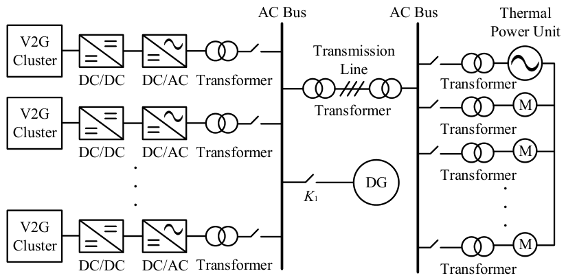
Based on the preceding assessments of V2G availability and diesel-generator capacity, and considering the auxiliary-power restoration requirements of the biomass CHP plant, a coordinated diesel generator–V2G black-start scheme is established. The diesel generator is used as the grid-forming source, while the fast power-response capability of the V2G cluster is used to assist the microgrid in maintaining transient stability. The structure of the coordinated diesel generator–V2G black-start system is shown in Figure 1.
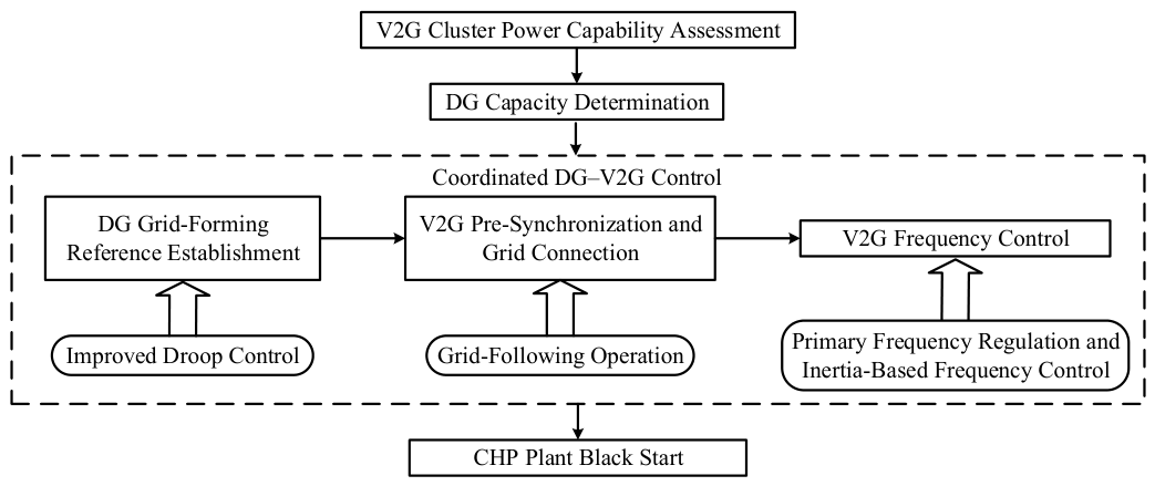
The multi-source coordinated black-start procedure is described as follows.
First, the diesel generator is started to establish the voltage and frequency references of the islanded microgrid through improved droop control. The plant medium-voltage bus and key feeders are then energized sequentially to form the initial power supply network.
Second, after the diesel generator establishes the bus voltage and frequency references, the V2G cluster tracks the voltage phase at the point of common coupling through its local PLL and connects to the system according to the predefined sequence. After grid connection, the V2G cluster enters a grid-connected standby state and gradually increases its base active-power output according to the auxiliary-load restoration plan, serving as the main active-power supply resource during black start.
Third, the plant auxiliary motors are started sequentially according to the cold-start procedure. During auxiliary startup, the diesel generator mainly performs grid-forming and voltage-support functions, while the V2G cluster provides fast active-power compensation according to the frequency deviation and rate of change in frequency. This reduces the impacts of auxiliary startup on the frequency and voltage of the islanded system, completes the initial restoration of the plant auxiliary-power system, and creates the conditions required for subsequent generating-unit startup.
The flowchart of the proposed diesel generator–V2G black-start scheme is shown in Figure 2.

2.2. Coordinated Control Strategy for the Diesel Generator–V2G System

During islanded network reconfiguration, an inappropriate control strategy may cause the transient impact associated with the connection of large-capacity auxiliaries to overload and destabilize the diesel generator, seriously threatening transient stability. Therefore, the conventional control strategies of both the diesel generator and the V2G cluster are improved in this study.

2.2.1. Improved Droop Control of the Diesel Generator

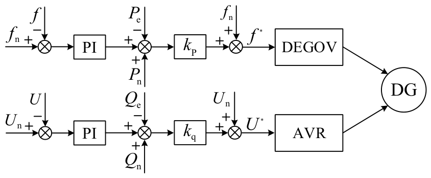
During the initial stage of islanded microgrid black start, the diesel generator serves as the primary grid-forming source and establishes the system voltage and frequency references through droop control. However, conventional droop control inherently introduces steady-state frequency and voltage deviations following load disturbances. To restore the frequency and voltage toward their nominal values after plant auxiliary-motor startup, local PI-based secondary correction loops are incorporated into the active-power–frequency and reactive-power–voltage droop channels. The correction signals are generated from locally measured frequency and voltage deviations, allowing the controller to operate autonomously without relying on a communication network. The resulting active-power–frequency (P–f) and reactive-power–voltage (Q–V) control equations are expressed as:
f n − f k pp + k ip s + P n − P e k p = f * − f n U n − U k pq + k iq s + Q n − Q e k q = U * − U n
where fn and Un are the rated frequency and rated bus voltage of the islanded microgrid, respectively; f and U are the measured system frequency and bus voltage; f* and U* are the frequency and voltage reference values generated by the improved droop controller; Pn and Qn are the base active- and reactive-power references of the diesel generator; Pe and Qe are the actual active- and reactive-power outputs of the diesel generator; kp and kq are the active-power/frequency and reactive-power/voltage droop coefficients; and kpp, kip, kpq, and kiq are the PI parameters for secondary frequency and voltage correction.
The diesel-generator control structure is shown in Figure 3. The diesel generator dynamically generates frequency and voltage references from the power deviations and secondary correction terms, and closed-loop regulation of prime-mover speed and stator-terminal voltage is implemented through the DEGOV governor system and the automatic voltage regulator (AVR), respectively.
During auxiliary startup, the diesel generator can rapidly regulate reactive-power output through the excitation system to suppress the bus-voltage dip caused by motor starting. In the active-power channel, however, the mechanical-power response is affected by the governor actuator and the fuel-supply process and can be approximated as:
P m = K a 1 + T a s e − τ d s Δ ω
where Ka is the actuator gain; Ta is the mechanical time constant; τd is the fuel engine delay time; and Δω is the angular frequency deviation.
According to the rotor-motion equation of the synchronous generator, the frequency variation in the islanded system is mainly determined by mechanical power, electromagnetic power, and rotor inertia, as expressed by:
2 H dg d Δ f d t = P m − P e − D Δ f
where Hdg is the inertia constant of the diesel generator, D is the damping coefficient, and Δf is the frequency deviation. Equations (8) and (9) indicate that during the initial stage of auxiliary startup, the mechanical power cannot immediately track the change in electromagnetic power; the resulting power imbalance directly causes a frequency deviation.

2.2.2. Inertia-Based Frequency Control and Primary Frequency Regulation of V2G

The diesel generator possesses physical rotational inertia and can suppress frequency fluctuations during the initial stage of a disturbance through changes in rotor kinetic energy. However, when subjected to the power impacts of large-capacity mixed auxiliaries, the kinetic-energy reserve of a single diesel generator is limited, which can readily trigger under-frequency load shedding or unit-trip protection. In contrast, the V2G cluster is connected to the AC system through bidirectional converters, and there is no inherent coupling between battery-side energy and system frequency. Therefore, under conventional grid-following control, the V2G cluster cannot spontaneously provide an inertial response. Frequency control must therefore be introduced into the V2G active-power loop so that the cluster can rapidly adjust active-power output according to system-frequency variations.
V2G converters can rapidly regulate active power and provide inertial and frequency support for low-inertia systems [22]. Accordingly, inertia-based frequency control is introduced into the V2G active-power loop. The control uses the real-time bus frequency f extracted by the PLL as the input. Through a nonlinear differentiating element, an additional power command is superimposed on the original V2G active-power reference, thereby producing an inertia-like effect similar to that of conventional grid-forming generating units and improving system-frequency stability in coordination with the diesel generator. The transient output of the inertia-based frequency controller is expressed as:
P f = N 1 d f d t N 2 , d f d t < 0 − N 1 d f d t N 2 , d f d t > 0
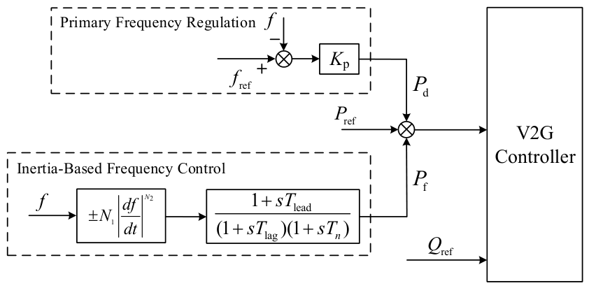
where f is the observed frequency of the islanded system; N1 is the inertia-support coefficient, which determines the response strength of the V2G cluster to the rate of change in frequency, and its value should be determined according to the maximum dispatchable power of V2G and the allowable frequency fluctuation range of the system; and N2 is the nonlinear regulation exponent, which is used to adjust the active-power support strength under disturbances of different magnitudes. To avoid high-frequency fluctuations in V2G output power caused by frequency measurement noise, the additional inertia command is processed by a lead-lag and low-pass composite compensation block before being superimposed on the V2G active-power reference.
Inertia-based frequency control mainly responds to the rate of change in frequency and can improve the frequency variation process at the initial stage of disturbance. To further reduce the frequency deviation, primary frequency regulation is introduced into the V2G control unit [23] so that the V2G clusters can regulate active-power output according to the frequency deviation and assist the diesel generator in completing frequency recovery. The V2G control system structure is shown in Figure 4.
In Figure 4, fref is the rated system frequency; Pref is the base active-power reference of the V2G cluster; Pd and Pf are the additional active-power commands generated by primary frequency regulation and inertia-based frequency control, respectively; Qref is the reactive-power reference; s is the Laplace operator; Tlead and Tlag are the lead and lag time constants, respectively; Tn is the noise-filtering time constant; and Kp is the primary frequency droop coefficient.

3. Simulation Results and Discussion

3.1. Simulation System and Case Setup

To numerically verify the general method presented in Section 2, a diesel generator–V2G coordinated black-start electromagnetic transient model was developed in PSCAD/EMTDC (version 5.0.2, Manitoba Hydro International Ltd., Winnipeg, MB, Canada) based on the actual auxiliary-power system of a biomass CHP plant located in an eastern province of China. The system topology, voltage levels, major equipment ratings, auxiliary-load operating powers, starting modes, and cold-start sequence were determined from plant design documents, equipment records, and actual operating information. The plant identity is not disclosed for confidentiality reasons.
This system was selected as the validation case because its two-level 10 kV/0.4 kV auxiliary network contains both direct-on-line and variable-frequency-driven motor loads, thereby representing the main types of source–load disturbances encountered during staged auxiliary-power restoration. It therefore provides a practical engineering scenario for evaluating the coordinated response of the grid-forming diesel generator and the grid-following V2G cluster during black start.
Although the numerical parameters adopted in this study are specific to the investigated plant, the proposed coordination framework can be extended to other islanded auxiliary-power microgrids with similar grid-forming and grid-following source structures. For systems with different voltage levels, source capacities, network impedances, or load compositions, the capacity configuration and control parameters should be recalculated according to the corresponding engineering conditions.
Full-scale field validation was not conducted because deliberate islanding and staged energization of the actual auxiliary-power system are constrained by plant operational and safety requirements.
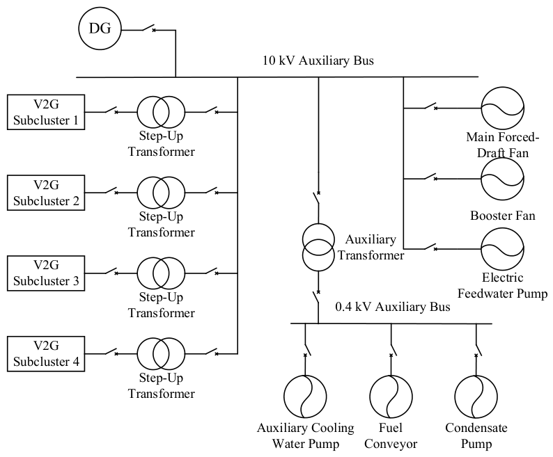
The system includes a diesel generator, a V2G cluster, and the auxiliary loads of a biomass CHP plant. The diesel generator is represented by a classical synchronous-machine model and is equipped with an IEEE Type 1 excitation system and a DEGOV governor. The V2G cluster consists of four independently controlled subclusters, each connected to the 10 kV auxiliary bus through a 0.4 MVA step-up transformer. The main forced-draft fan, booster fan, and electric feedwater pump are connected to the 10 kV auxiliary bus, while the auxiliary cooling-water pump, fuel conveyor, and condensate pump are connected to the 0.4 kV auxiliary bus through a 10/0.4 kV auxiliary transformer. The simulation-system topology is shown in Figure 5.
According to the cold-start process of the biomass CHP plant, the plant auxiliaries are started in the following order: auxiliary cooling-water pump, main forced-draft fan, booster fan, fuel conveyor, condensate pump, and electric feedwater pump. To represent their actual starting characteristics, the auxiliary cooling-water pump and fuel conveyor on the 0.4 kV side are started directly across the line, each with an operating power of 144 kW; their rotor inertia time constants are 1.25 s and 1.00 s, respectively. The main forced-draft fan, booster fan, and electric feedwater pump on the 10 kV side, together with the condensate pump on the 0.4 kV side, are started using variable-frequency soft starting. Their rated powers are 847, 610, 553, and 189 kW, respectively; their operating powers are set to 80, 260, 77, and 16 kW; and their rotor inertia time constants are 3.00, 3.00, 1.50, and 2.00 s, respectively. The equipment ratings, operating-power settings, starting modes, and motor inertia parameters used in the simulation were taken from the corresponding plant equipment data and operating records.
The total simulation duration is 120 s. During the initial stage, the diesel generator establishes the voltage and frequency of the islanded system. To reduce the transient impact caused by simultaneous V2G connections, the four V2G subclusters are connected in two batches: the first batch at 5 s and the second batch at 10 s. After grid connection, the V2G cluster tracks the base active-power command corresponding to each auxiliary-restoration stage and provides primary frequency regulation and inertia-based frequency support during frequency disturbances. Beginning at 15 s, the plant auxiliaries are connected sequentially at 15 s intervals according to the predefined order to simulate staged load restoration during black start.
The 120 s simulation horizon is selected as an electrical-transient observation window rather than the actual duration of the complete plant black-start process. The 15 s interval between successive auxiliary startups is used to separate the individual transient responses and facilitate comparison of the control performance, while the final startup at 90 s is followed by a 30 s observation period to evaluate the post-disturbance recovery of the system.

3.2. Capacity Configuration of the Black-Start Sources

Unless otherwise stated, the plant-side electrical and load parameters are obtained from the actual plant data described in Section 3.1, whereas the V2G available capacity, energy reserve, and diesel-generator capacity are calculated using Equations (1)–(6) based on the specified operating conditions.
For the representative case, the total number of EVs in the considered microgrid area is set to 50. The vehicle plug-in probability at the onset of the outage, the post-outage cumulative disconnection ratio, and the local PLL synchronization success coefficient are set to 0.70, 0.20, and 0.90, respectively. Substitution into Equation (1) gives an expected available fleet size of 25.2 EVs. For the subsequent electromagnetic transient simulation, an integer resource level of 25 EVs is adopted, which is slightly conservative relative to the expected value. Accordingly, the stochastic availability assessment is used to determine the representative V2G resource level, while the subsequent EMT simulation evaluates the dynamic black-start performance under this resource configuration. The rated power of each bidirectional EV converter is 20 kW, and the initial cluster SOC is above the minimum safe discharge limit. Equation (2) therefore gives an available V2G active-power capacity of 0.50 MW. Considering the 0.72 MW steady-state active-power demand of the auxiliary-power system, the V2G cluster is scheduled to supply 0.40 MW in steady state, while the remaining 0.32 MW is supplied by the diesel generator. Accordingly, 0.10 MW of upward regulation margin is reserved for primary frequency regulation and inertia-based frequency control.
The energy capacity of the V2G cluster is verified according to the sustained energy-supply requirement during black-start restoration. The rated battery energy of each EV is 60 kWh; therefore, 25 effective vehicles correspond to a total rated cluster battery energy of 1.50 MWh. The initial equivalent SOC of the cluster is 0.70, and the minimum safe discharge SOC is 0.30, yielding an available discharge energy of 0.60 MWh. Using a continuous V2G supply at 0.40 MW for 1 h as a representative verification case, the required output energy is 0.40 MWh, leaving an energy margin of 0.20 MWh. Therefore, the sustained energy-supply requirement is satisfied.
As the grid-forming source, the diesel generator must satisfy both the steady-state apparent-power demand after all auxiliaries have been connected and the transient voltage-support requirement during the startup of the largest direct-on-line auxiliary. For capacity verification, the steady-state active and reactive loads are taken as 0.72 MW and 0.25 Mvar, respectively. With the V2G cluster supplying 0.40 MW of steady-state active power, the diesel generator supplies 0.32 MW of active power, corresponding to a steady-state apparent-power requirement of 0.406 MVA. The largest direct-on-line auxiliary on the 0.4 kV side has an operating power of 144 kW. According to the starting characteristics of the induction-motor model used in the simulation, its starting current is approximately four times the rated current, corresponding to a transient apparent-power impact of 0.53 MVA. Taking the diesel-generator subtransient reactance as 0.14 p.u., the maximum allowable voltage dip of the 10 kV auxiliary bus as 0.10 p.u., and the pre-start diesel-generator apparent power as 0.31 MVA, Equation (6) gives a minimum required diesel-generator capacity of 1.052 MVA. A 1.4 MVA diesel generator is therefore selected as the grid-forming source, providing a capacity margin of 33.1% above the calculated minimum requirement. The main control parameters of the black-start sources are listed in Table 1.
The control parameters in Table 1 are design and tuning parameters used for the proposed controllers rather than plant equipment ratings; the droop coefficients are determined from the adopted droop characteristics, while the remaining controller parameters are selected through controller tuning under the studied operating conditions.

3.3. Startup Characteristics of Mixed Auxiliary-Motor Loads

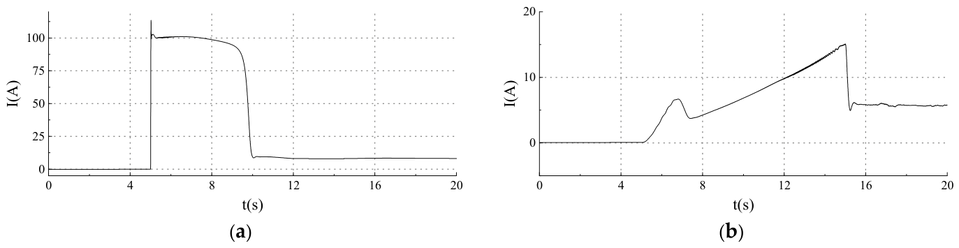
To analyze the influence of different starting methods on the black-start dynamic process, the electric feedwater pump is selected as a representative large-capacity auxiliary, and two comparison cases are established: direct-on-line starting at grid frequency and variable-frequency soft starting. These cases are used only to compare the current characteristics of the two starting methods; in the actual black-start restoration sequence, the electric feedwater pump is started using the variable-frequency method. The stator current responses under the two starting methods are shown in Figure 6.
As shown in Figure 6, during direct-on-line starting, the stator current rises sharply when the motor is connected, with a peak exceeding 100 A, and the high-current interval lasts for about 5 s. In contrast, with variable-frequency soft starting, the converter gradually increases the output voltage and frequency according to the prescribed V/f relationship, limiting the starting-current peak to 15 A and producing a much smoother current response. Compared with direct-on-line starting, variable-frequency soft starting therefore substantially reduces both the magnitude and abruptness of the starting current, thereby mitigating the transient impact of large-capacity auxiliaries on the black-start system.
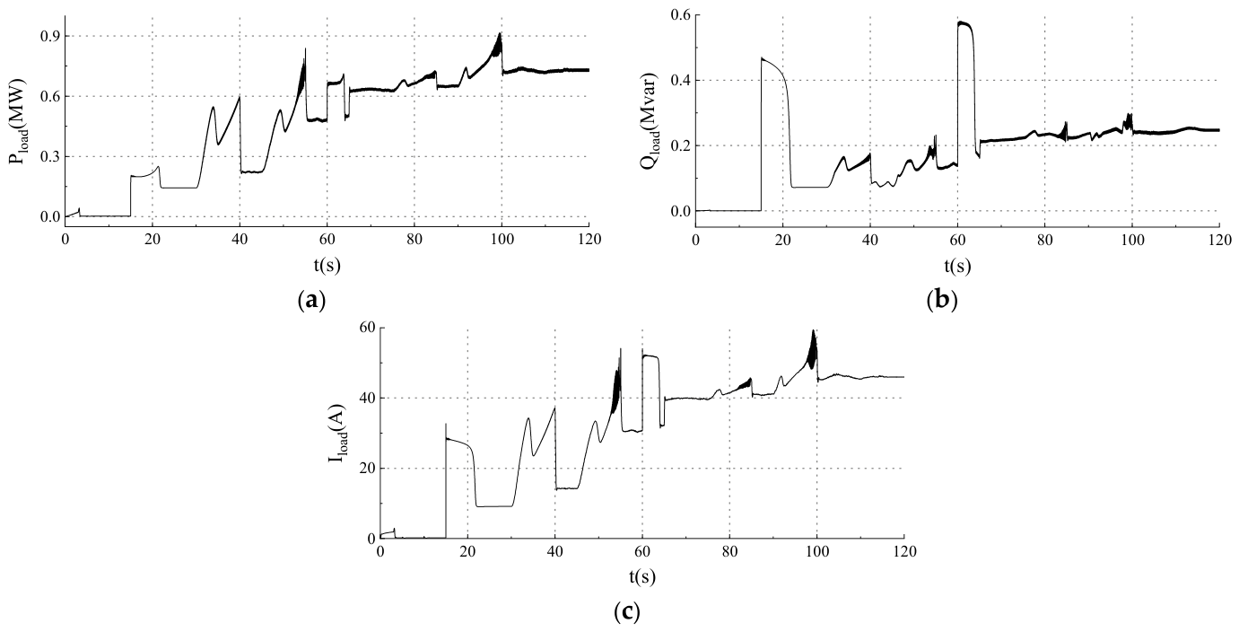
To characterize the normal starting behavior of the plant auxiliaries, Figure 7 shows the active power, reactive power, and total feeder current as the auxiliaries are connected according to the predefined sequence.
As shown in Figure 7, the system active load increases in a stepwise manner as the plant auxiliaries are connected, with short-duration power variations during the acceleration of variable-frequency-started motors. After all auxiliaries are connected, the steady-state active and reactive powers are 0.72 MW and 0.25 Mvar, respectively, and the total feeder current settles at 46 A. The steady-state active power differs from the predefined total operating-power demand of 0.721 MW by less than 1%, indicating good consistency between the specified load demand and the simulated steady-state response. During the two direct-on-line startup events at t = 15 s and t = 60 s, the reactive-power peaks reach 0.47 Mvar and 0.58 Mvar, respectively, while the corresponding feeder currents rise to 29 A and 52 A. In contrast, the variable-frequency-started auxiliaries exhibit smoother reactive-power and current variations during startup. These quantitative results indicate that the two starting modes produce distinctly different transient load characteristics, with direct-on-line starting causing more abrupt reactive-power and current changes and therefore a stronger instantaneous impact on the auxiliary-power system.

3.4. Analysis of Coordinated Diesel Generator–V2G Black-Start Results

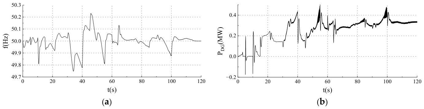
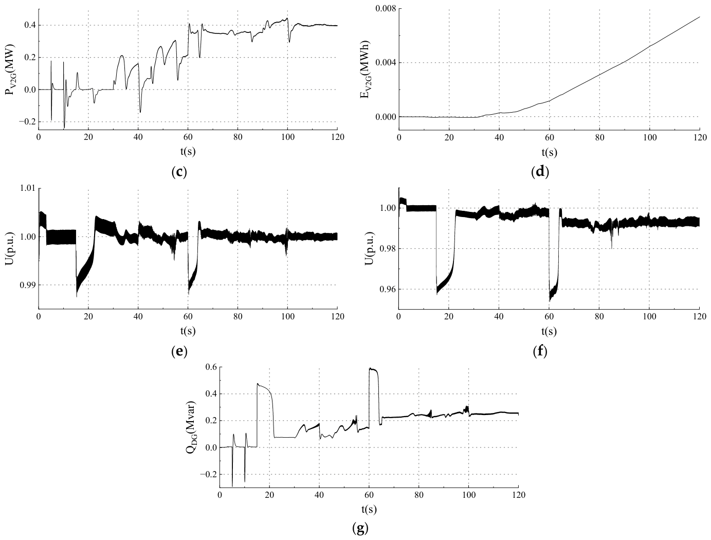
To verify the dynamic support performance of the proposed diesel generator–V2G coordinated control strategy during black start, this section analyzes the system frequency, diesel-generator output power, V2G-cluster output power, and bus-voltage responses. The black-start transient responses are shown in Figure 8.
Figure 8a–d show the system frequency, diesel-generator active power, total V2G-cluster active power, and cumulative V2G output energy, respectively. After an auxiliary is connected, the diesel generator cannot immediately compensate for the active-power deficit during the initial startup period because of delays in the governor and fuel system. The V2G cluster rapidly adjusts its active-power output according to the frequency deviation and the rate of change in frequency, suppressing frequency fluctuations caused by the source–load imbalance. The diesel generator then gradually assumes the newly added load and re-establishes power balance. During the entire restoration process, the minimum and maximum system frequencies are 49.75 Hz and 50.23 Hz, corresponding to deviations of −0.50% and +0.46% from the nominal frequency of 50 Hz, respectively. After all auxiliaries are connected, the active-power outputs of the diesel generator and the V2G cluster stabilize at 0.32 MW and 0.40 MW, respectively, which is consistent with the predefined power allocation. During the 120 s transient restoration process, the cumulative V2G output energy reaches 0.0075 MWh, corresponding to only 1.25% of the available 0.60 MWh, which is consistent with the preceding sustained energy-supply verification.
Figure 8e–g show the 10 kV auxiliary-bus voltage, the 0.4 kV bus voltage, and the diesel-generator reactive-power output, respectively. When the two direct-on-line auxiliaries are connected at t = 15 s and t = 60 s, the reactive-power demand and starting current increase rapidly, causing short-duration voltage dips at both voltage levels. The minimum voltages of the 10 kV and 0.4 kV buses are 0.988 p.u. and 0.955 p.u., corresponding to maximum voltage dips of 1.2% and 4.5% from their nominal values, respectively. Through excitation control and secondary voltage correction, the diesel generator rapidly increases its reactive-power output; the reactive-power peaks during the two direct-on-line startup events reach 0.47 Mvar and 0.58 Mvar, respectively. After the disturbances subside, the voltages at both bus levels recover to values close to their rated levels. These results show that the adopted diesel-generator grid-forming and voltage-regulation strategy can mitigate the voltage impact associated with the transient reactive-power demand of direct-on-line auxiliary startup and support bus-voltage recovery throughout the black-start process.
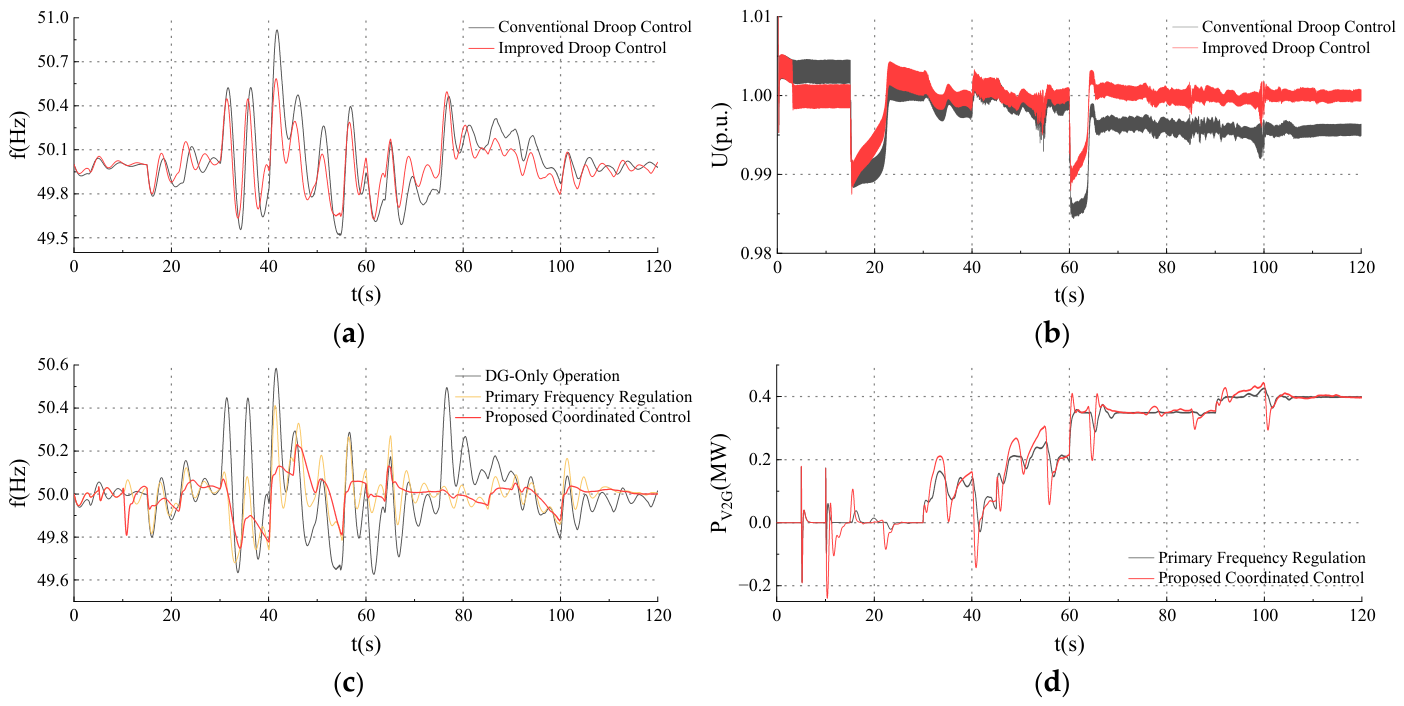
To further quantify the contributions of the individual control components to black-start dynamic performance, three comparison cases are established while keeping the auxiliary startup sequence and system parameters unchanged: (i) diesel-generator-only black start with conventional droop control; (ii) diesel-generator-only black start with the improved droop control proposed in this paper; and (iii) coordinated black start in which the diesel generator uses the proposed control while V2G participates only in primary frequency regulation. Figure 9a,b compare the first two cases to verify the effect of the improved diesel-generator control. Figure 9c,d then compare diesel-generator-only operation, V2G primary frequency regulation, and the complete coordinated control while keeping the diesel-generator control unchanged, thereby evaluating the effects of V2G primary frequency regulation and inertia-based frequency control on the system frequency dynamics.
Figure 9a,b show the system-frequency and 10 kV bus-voltage responses under different diesel-generator control strategies. Under conventional droop control, the system frequency varies between 49.5 and 50.9 Hz, with a peak-to-valley range of 1.40 Hz. With the improved droop control, the frequency variation is reduced to 49.6–50.6 Hz, and the peak-to-valley range calculated from the simulated response decreases to 0.95 Hz, corresponding to a reduction of 32.1%. In addition, the frequency deviation following successive load disturbances is gradually eliminated. For the voltage response, taking the direct-on-line auxiliary startup at t = 60 s as an example, the minimum 10 kV bus voltage increases from 0.985 p.u. under conventional droop control to 0.989 p.u. under the improved control. After the disturbance, the voltage settles at 0.995 p.u. under conventional droop control, whereas the improved control restores it close to the nominal value of 1.0 p.u. This indicates that the secondary frequency and voltage correction not only reduces frequency fluctuations during black start but also substantially mitigates the steady-state frequency and voltage deviations inherent in conventional droop control, thereby improving the restoration performance of the diesel generator during islanded operation.
Figure 9c,d further show the system-frequency and V2G-cluster active-power responses under different V2G support modes. The frequency peak-to-valley ranges under diesel-generator-only operation, V2G primary frequency regulation only, and the complete coordinated control are 0.95 Hz, 0.74 Hz, and 0.48 Hz, respectively. Relative to diesel-generator-only operation, introducing V2G primary frequency regulation reduces the frequency-fluctuation range by 22.1%. Adding inertia-based frequency control further reduces the range by 35.1% relative to primary frequency regulation alone and by 49.5% relative to diesel-generator-only operation. As shown in Figure 9d, during the load disturbances near 35 s and 55 s, the peak transient V2G power increments under the proposed control reach 0.21 MW and 0.30 MW, respectively, which are 0.05 MW and 0.06 MW higher than those obtained with primary frequency regulation alone. These results demonstrate that inertia-based frequency control provides faster active-power support during the initial stage of a disturbance by responding to the rate of change in frequency. Both V2G control modes eventually settle at 0.40 MW, indicating that the inertia-based frequency control primarily improves transient frequency-support capability without altering the steady-state V2G power allocation.


4. Conclusions

To address the limitations of conventional black-start sources associated with geographical conditions and capacity configuration, and considering the restoration of plant auxiliary power for a biomass CHP plant, this paper proposes a coordinated black-start control method for a diesel generator with V2G-assisted frequency support. The main conclusions are as follows:
(1)
An available-capacity assessment model for a V2G cluster is established considering vehicle connection status, SOC, and converter-capacity constraints. The diesel-generator capacity is then verified based on the steady-state auxiliary load and the impact of direct-on-line startup, enabling coordinated configuration of the available V2G resources and diesel-generator capacity and providing a basis for coordinated black-start source configuration.
(2)
A diesel generator–V2G coordinated black-start framework is developed, forming a restoration sequence that includes diesel-generator grid formation, V2G synchronization and grid connection, and sequential restoration of plant auxiliaries. Functional coordination between the two types of sources enables islanded grid formation, steady-state power supply, and transient power support.
(3)
The proposed coordinated control effectively improves the frequency and voltage dynamics during black start. Relative to conventional droop control, the improved diesel-generator control reduces the system frequency peak-to-valley range from 1.40 Hz to 0.95 Hz, corresponding to a reduction of 32.1%, while also improving bus-voltage recovery. With V2G primary frequency regulation, the frequency peak-to-valley range is further reduced to 0.74 Hz. After inertia-based frequency control is added, it decreases to 0.48 Hz, representing an overall reduction of 49.5% relative to diesel-generator-only operation with the improved droop control. These results demonstrate that the improved diesel-generator control and fast V2G active-power support jointly enhance the dynamic restoration performance during successive auxiliary-motor startup.

Author Contributions

Conceptualization, H.Z., J.L. and P.H.; methodology, J.W. and P.H.; validation, J.W. and J.L.; formal analysis, J.W.; investigation, J.W.; resources, H.Z. and J.L.; data curation, J.W.; writing—original draft preparation, J.W.; writing—review and editing, H.Z., J.L. and P.H.; visualization, J.W.; supervision, P.H.; project administration, H.Z. and J.L.; funding acquisition, H.Z. and J.L. All authors have read and agreed to the published version of the manuscript.

Funding

This research was funded by the 2025 Laboratory Open Fund Project of the Beijing Electric Vehicle Charging Engineering Technology Research Center, “Research on Key Technologies for Black-Start Simulation and Verification of Thermal Power Units Coordinated with Electric-Vehicle V2G”, under grant number YD80-25-002.

Data Availability Statement

The original contributions presented in this study are included in the article. Further inquiries can be directed to the corresponding author.

Conflicts of Interest

Authors H.Z. and J.L. were employed by China Electric Power Research Institute Co., Ltd. Authors P.H. and J.W. are affiliated with Hefei University of Technology. All authors declare that the research was conducted in the absence of any commercial or financial relationships that could be construed as a potential conflict of interest.

References

  1. Heidari-Akhijahani, A.; Butler-Purry, K.L. A Review on Black-Start Service Restoration of Active Distribution Systems and Microgrids. Energies 2024, 17, 100. [Google Scholar] [CrossRef] [Scilit]
  2. Pan, Z.; Jenkins, N.; Wu, J. Black Start from Renewable Energy Resources: Review and a Case Study of Great Britain. Renew. Sustain. Energy Rev. 2025, 209, 115143. [Google Scholar] [CrossRef] [Scilit]
  3. Du, Y.; Tu, H.; Lu, X.; Wang, J.; Lukic, S. Black-Start and Service Restoration in Resilient Distribution Systems with Dynamic Microgrids. IEEE J. Emerg. Sel. Top. Power Electron. 2022, 10, 3975–3986. [Google Scholar] [CrossRef] [Scilit]
  4. Maharjan, S.; Cong, B.; Wang, H.; Yao, Y.; Ding, F.; Wang, Z. Distribution System Blackstart and Restoration Using DERs and Dynamically Formed Microgrids. IEEE Trans. Smart Grid 2025, 16, 2100–2114. [Google Scholar] [CrossRef] [Scilit]
  5. Yan, W.; Hong, Q.; Liu, D.; Dyśko, A. Feasibility Studies on Black Start Capability of Distributed Energy Resources. In Proceedings of the 10th Renewable Power Generation Conference (RPG 2021), Online Conference, 14–15 October 2021; pp. 869–875. [Google Scholar] [CrossRef] [Scilit]
  6. Li, Y.; Ren, X.; Ni, Z.; Zhao, T.; Ge, L.; Li, X.; Luo, Y.; Zhao, Y. Shared Energy and Reserve Based Coordinated Operation Between Electric Vehicle Charging Stations and Distribution Power Network. IEEE Trans. Ind. Appl. 2023, 59, 4584–4597. [Google Scholar] [CrossRef] [Scilit]
  7. Corinaldesi, C.; Lettner, G.; Schwabeneder, D.; Ajanovic, A.; Auer, H. Impact of Different Charging Strategies for Electric Vehicles in an Austrian Office Site. Energies 2020, 13, 5858. [Google Scholar] [CrossRef] [Scilit]
  8. Zeng, F.; Wei, Z.; Sun, G.; Wang, M.; Han, H. Frequency Regulation of Electric Vehicle Aggregator Considering User Requirements with Limited Data Collection. Energies 2023, 16, 848. [Google Scholar] [CrossRef] [Scilit]
  9. O’Malley, C.; Badesa, L.; Teng, F.; Strbac, G. Frequency Response from Aggregated V2G Chargers with Uncertain EV Connections. IEEE Trans. Power Syst. 2023, 38, 3543–3556. [Google Scholar] [CrossRef] [Scilit]
  10. Deng, X.; Zhang, Q.; Li, Y.; Sun, T.; Yue, H. Hierarchical Distributed Frequency Regulation Strategy of Electric Vehicle Cluster Considering Demand Charging Load Optimization. IEEE Trans. Ind. Appl. 2022, 58, 720–731. [Google Scholar] [CrossRef] [Scilit]
  11. Yumiki, S.; Susuki, Y.; Oshikubo, Y.; Ota, Y.; Masegi, R.; Kawashima, A.; Ishigame, A.; Inagaki, S.; Suzuki, T. Autonomous Vehicle-to-Grid Design for Provision of Frequency Control Ancillary Service and Distribution Voltage Regulation. Sustain. Energy Grids Netw. 2022, 30, 100664. [Google Scholar] [CrossRef] [Scilit]
  12. Shrivastava, S.; Khalid, S.; Nishad, D.K. Impact of EV Interfacing on Peak-Shelving and Frequency Regulation in a Microgrid. Sci. Rep. 2024, 14, 31514. [Google Scholar] [CrossRef] [Scilit] [PubMed]
  13. Mojumder, M.R.H.; Ahmed Antara, F.; Hasanuzzaman, M.; Alamri, B.; Alsharef, M. Electric Vehicle-to-Grid (V2G) Technologies: Impact on the Power Grid and Battery. Sustainability 2022, 14, 13856. [Google Scholar] [CrossRef] [Scilit]
  14. Wen, M.; Shi, H.; Li, B.; Jiang, Q.; Liu, T.; Ding, C. Research on the Coordinated Recovery Strategy Based on Centralized Electric Vehicle Charging Station. Energies 2023, 16, 5401. [Google Scholar] [CrossRef] [Scilit]
  15. Zhang, L.; Jiang, S.; Zhang, B.; Li, G.; Wang, Z.; Tang, W. Coordinated Optimization of Emergency Power Vehicles and Distribution Network Reconfiguration Considering the Uncertain Restoration Capability of E-Taxis. IEEE Trans. Ind. Appl. 2022, 58, 2707–2717. [Google Scholar] [CrossRef] [Scilit]
  16. Dong, X.; Xiong, X.; Yang, D.; Wang, S.; Zhu, Y. Power Supply Resilience under Typhoon Disasters: A Recovery Strategy Considering the Coordinated Dispatchable Potential of Electric Vehicles and Mobile Energy Storage. Processes 2025, 13, 1638. [Google Scholar] [CrossRef] [Scilit]
  17. Zhang, C.; Dou, X.; Zhao, J.; Hu, Q.; Liu, K.; Lv, Y. Distributed Forced-Boundary-Constrained Secondary Coordination of Islanded Microgrids. IEEE Trans. Ind. Appl. 2025, 61, 5161–5172. [Google Scholar] [CrossRef] [Scilit]
  18. Amrr, S.M.; Zaery, M.; Hussain, S.M.S.; Abido, M.A. Exact Time Convergent Distributed Secondary Frequency and Voltage Control for AC Microgrid. IEEE Trans. Ind. Appl. 2026, 62, 194–206. [Google Scholar] [CrossRef] [Scilit]
  19. Huang, S.; Wang, Q.; Xiong, L.; Zhou, Y.; Gao, F.; Huang, W.; Zhu, L.; Li, Y. Dynamic Event-Triggered-Based Privacy-Preserving Secondary Control for AC Microgrids with Optimal Power Allocation via State Decomposition. IEEE Trans. Ind. Appl. 2026, 62, 3248–3260. [Google Scholar] [CrossRef] [Scilit]
  20. Varetsky, Y.; Gajdzica, M. Power Compatibility of Induction Motors in Industrial Grids Containing Synchronous Generators. Energies 2024, 17, 1066. [Google Scholar] [CrossRef] [Scilit]
  21. Iqbal, S.; Habib, S.; Ali, M.; Shafiq, A.; ur Rehman, A.; Ahmed, E.M.; Khurshaid, T.; Kamel, S. The Impact of V2G Charging/Discharging Strategy on the Microgrid Environment Considering Stochastic Methods. Sustainability 2022, 14, 13211. [Google Scholar] [CrossRef] [Scilit]
  22. Thangavel Sampathkumar, N.; Shanmugam Velu, A.; Rajasekaran, B.; Raguru Pandu, K.D. Virtual Inertia of Electric Vehicle Fast Charging Stations with Dual Droop Control and Augmented Frequency Support. Sustainability 2025, 17, 8997. [Google Scholar] [CrossRef] [Scilit]
  23. Suh, J.; Song, S.; Jang, G. Power Imbalance-Based Droop Control for Vehicle to Grid in Primary Frequency Regulation. IET Gener. Transm. Distrib. 2022, 16, 3374–3383. [Google Scholar] [CrossRef] [Scilit]
Figure 1. General configuration of the proposed diesel generator–V2G black-start system.
Electronics 15 04563 g001
Figure 2. Flowchart of the diesel generator–V2G coordinated black-start scheme.
Electronics 15 04563 g002
Figure 3. Control system block diagram of the diesel generator.
Electronics 15 04563 g003
Figure 4. Control block diagram of the V2G cluster.
Electronics 15 04563 g004
Figure 5. Topology of the simulation system.
Electronics 15 04563 g005
Figure 6. Comparison of stator current responses during electric feedwater pump startup. (a) Direct-on-line startup; (b) variable-frequency startup.
Electronics 15 04563 g006
Figure 7. Power and current responses of auxiliary loads. (a) Active load power; (b) reactive load power; (c) total feeder current.
Electronics 15 04563 g007
Figure 8. Transient response waveforms of diesel generator–V2G coordinated black start. (a) system frequency; (b) diesel-generator active power; (c) total V2G-cluster active power; (d) cumulative V2G output energy; (e) 10 kV bus-voltage magnitude; (f) 0.4 kV bus-voltage magnitude; (g) diesel-generator reactive power.
Electronics 15 04563 g008aElectronics 15 04563 g008b
Figure 9. Black-start dynamic responses under different control strategies. (a) system-frequency response under different diesel-generator controls; (b) 10 kV bus-voltage response under different diesel-generator controls; (c) system frequency under different black-start control modes; (d) V2G-cluster active-power response under different V2G control modes.
Electronics 15 04563 g009
Table 1. Key parameters of the simulation system.
Parameter CategoryParameter/UnitValue
Diesel generatorActive-power droop coefficient kp/(Hz/MW)1.71
Reactive-power droop coefficient kq/(kV/Mvar)0.34
Secondary frequency/voltage proportional gain kpp/kpq10.00
Secondary frequency/voltage integral gain kip/kiq40.00
V2G clusterInertia-support coefficient N1/[ MW / ( Hz / s ) N 2 ]0.35
Nonlinear regulation exponent N20.70
Primary frequency droop coefficient KP/(MW/Hz)0.32
Lead time constant Tlead/(s)0.05
Lag time constant Tlag/(s)0.01
Noise-filtering time constant Tn/(s)0.02
Disclaimer/Publisher’s Note: The statements, opinions and data contained in all publications are solely those of the individual author(s) and contributor(s) and not of MDPI and/or the editor(s). MDPI and/or the editor(s) disclaim responsibility for any injury to people or property resulting from any ideas, methods, instructions or products referred to in the content.