Article

Phase Change Material-Coupled Operation Condition Adaptive Liquid-Cooling Strategy for Energy Storage Battery Thermal Management


1
Inner Mongolia Huadian Hydrogen Energy Technology Co., Ltd., Baotou 014000, China
2
School of Energy Power and Mechanical Engineering, North China Electric Power University, Beijing 102206, China
*
Author to whom correspondence should be addressed.
Electronics 2026, 15(18), 4261; https://doi.org/10.3390/electronics15184261 (registering DOI)
Submission received: 4 July 2026 / Revised: 25 August 2026 / Accepted: 3 September 2026 / Published: 18 September 2026
(This article belongs to the Special Issue Optimization Control of Distributed Renewable Energy Systems)

Abstract

Thermal management is important for ensuring the safety and reliability of energy storage batteries. Conventional single-mode cooling methods fail to maintain efficiency and temperature uniformity under variable operating conditions. This study presents a phase change material (PCM)-coupled liquid-cooling strategy with an operation condition adaptive control scheme for large-capacity energy storage batteries. A battery management system numerical model with paraffin/expanded composite PCM and a parallel-channel liquid cold plate was developed. The thermal management performance of this system was comprehensively validated under different coolant flow rates, inlet temperatures, PCM melting points, and latent heats, followed by a quantitative sensitivity analysis to identify dominant influencing factors. Based on the parametric analysis, an adaptive cooling strategy was proposed: passive PCM cooling is adopted at low charge/discharge rates, while a delayed liquid-cooling activation strategy is implemented at a high rate to fully use PCM latent heat and reduce energy consumption. Results denote that this system reduces the battery surface maximum temperature by 5.1 °C and the maximum temperature difference by 2.62 °C compared with liquid cooling alone. The coolant flow rate exerts the greatest influence on both the temperature difference and the maximum temperature through the sensitivity analysis, followed by the PCM melting point, coolant temperature, and latent heat. Under the delayed cooling strategy, the total liquid-cooling runtime during continuous operation is reduced by 1720 s, with the number of cooling cycles decreasing from eight to three. This work provides an engineering-based, operation-adaptive thermal management solution that significantly enhances the temperature control effectiveness, energy efficiency, and operational safety of energy storage power stations under real-world variable working conditions.

1. Introduction

Large-scale stationary energy storage has become an important means of improving the stability and flexibility of power grids [1,2]. With the rapid expansion of battery energy storage, operational safety has become an increasing concern [3], particularly the prevention of thermal runaway [4] and the maintenance of battery health during long-term operation [5]. Among the available technologies, lithium-ion batteries have become a major option for grid-scale and integrated energy storage applications because of high energy density and technological maturity [6,7,8]. At the broader energy system level, advanced operation and resilient control methods have also been increasingly investigated to improve system flexibility and operational reliability [9,10,11]. However, heat accumulation during charge and discharge may cause non-uniform temperature distribution and excessive temperature rise within the battery module [12]. Prolonged exposure to unsuitable thermal conditions can accelerate performance degradation, making effective thermal management essential for maintaining battery reliability [13,14]. In severe cases, localized overheating may initiate thermal runaway and promote its propagation within the battery system [15]. Hence, developing an efficient and robust battery thermal management system (BTMS) is essential.
Liquid cooling is one of the main active cooling methods used in BTMSs [16]. By circulating coolant through cold plates, it provides an efficient and controllable heat removal path [17,18]. Parallel and serpentine channels are commonly employed to improve coolant distribution. In contrast, PCM cooling utilizes latent heat absorption to buffer battery temperature rise and can be combined with liquid cooling to achieve complementary thermal regulation [19]. Nevertheless, its active nature necessitates continuous pump operation, leading to substantial energy consumption [20,21]. Wu et al. [22] comprehensively reviewed liquid-cooled battery thermal management systems and emphasized that the cold-plate configuration, coolant distribution, and multi-objective optimization are key factors affecting cooling performance and pumping power. Niu et al. [23] optimized serpentine-channel cold plates using an orthogonal experimental design and demonstrated that appropriate channel dimensions and coolant flow rates can improve the cooling performance. Zhang et al. [24] highlighted that liquid cooling, including cold-plate and immersion cooling technologies, has become the mainstream solution for high-energy-density battery systems because of its superior heat transfer capability. Conversely, PCM-based passive cooling leverages latent heat absorption to buffer temperature spikes without energy input, offering an inherently energy-efficient solution [25,26]. However, the application of PCM alone is constrained by its low thermal conductivity and limited heat storage capacity; once fully melted, the PCM loses its temperature regulation capability, causing rapid temperature rise [27,28]. Wang et al. [29] further demonstrated that incorporating MXene and flame-retardant additives into composite PCM can simultaneously improve heat dissipation and fire safety. In addition, Yang et al. [30] reported that expanded graphite/paraffin-composite PCM effectively reduced the peak temperature. More recently, Yuan et al. [31] highlighted that hybrid thermal management systems integrating PCM with liquid cooling or heat pipes have emerged as a promising strategy to overcome the thermal saturation issue of standalone PCM systems while maintaining low energy consumption.
Therefore, hybrid PCM–liquid-cooling systems have drawn much attention, aiming to synergize the high heat transfer capacity of liquid cooling with the passive temperature buffering effect of PCM [32,33,34,35]. Several studies have investigated such coupled systems. For instance, the incorporation of PCM has been shown to reduce the peak temperature rise during high-rate discharge. Furthermore, structural optimizations of cold plates, such as varying channel geometries or adding fins, have been explored for thermal performance. Xu et al. [36] proposed a PCM–liquid hybrid cooling system and reported substantial improvements in maximum temperature control compared with PCM cooling strategies. Balasubramanian et al. [37] further showed that incorporating nano-doped PCM into a liquid-cooled BTMS significantly enhanced heat dissipation and delayed PCM thermal saturation under high-rate operation. In addition, Hyun et al. [38] optimized the cooling channel configuration of a PCM–liquid hybrid system and found that appropriate channel arrangements could effectively improve the temperature distribution throughout the battery pack. More recently, Zhang et al. [39] developed a microchannel liquid-cooling/PCM integrated BTMS and demonstrated superior thermal regulation over a wide operating temperature range through a staged heat transfer mechanism. Ma et al. [40] developed a PCM–liquid hybrid BTMS framework for delayed cooling coordination under representative operating conditions. These studies collectively indicate that hybrid PCM–liquid-cooling systems can effectively mitigate the thermal conductivity limitations of PCM while reducing the cooling demand and pumping power associated with conventional liquid-cooling systems. Except for these advances, existing studies focus primarily on the steady-state cooling performance under fixed operating conditions, with limited attention to the transient interactions between PCM melting dynamics and liquid-cooling start-up. Accordingly, the main distinction of the present work from the above studies lies in the operation rate-dependent coordination of PCM thermal buffering and delayed liquid-cooling activation, rather than in the hybrid PCM–liquid configuration itself. Figure 1 shows the knowledge gap between our methods and the existing hybrid PCM–liquid-cooling studies.
In practical energy storage applications, the battery is rarely operated under constant working conditions. Instead, it frequently experiences varying charge/discharge rates and fluctuating ambient temperatures, resulting in dynamic heat generation characteristics [41,42,43]. Under such circumstances, the single cooling mode may not always provide a balance between energy efficiency and thermal safety. Specifically, continuous liquid cooling can effectively suppress temperature rise but may incur unnecessary auxiliary energy consumption during low charge/discharge rate. In contrast, PCM-based passive cooling offers excellent energy-saving potential, but its thermal regulation capability gradually deteriorates as the latent heat storage capacity is depleted, particularly under a high charge/discharge rate. Consequently, dynamically coordinating passive and active cooling based on the battery operation state represents a promising way for achieving effective temperature control. In addition, the influences of key parameters on the thermal behavior of the system have not yet been fully elucidated. This lack of systematic understanding limits the development of adaptive control strategies and hinders the optimal design of hybrid BTMSs.
Furthermore, although PCM–liquid-cooling thermal management systems have been extensively investigated, existing studies have focused on cooling structure optimization and thermal performance evaluation under fixed operating conditions, while less attention has been paid to the dynamic coordination between PCM phase change heat storage and liquid-cooling activation under different thermal loads. For large-capacity energy storage batteries, systematic investigations are still lacking on how to appropriately switch between active liquid cooling and passive PCM cooling according to the charge/discharge rate while maintaining effective temperature control and reducing unnecessary liquid-cooling operation. In addition, the effects of liquid-cooling operating parameters and PCM thermophysical properties on the thermal performance and control strategy of the coupled system have not been fully clarified. Therefore, it is necessary to investigate a coordinated PCM–liquid-cooling thermal management strategy for different operating conditions.
To address these gaps, this paper presents a PCM-coupled liquid-cooling BTMS with an operation condition adaptive control strategy for large-capacity energy storage batteries. A three-dimensional numerical model of the PCM-coupled liquid-cooling BTMS is established. The cooling performance of the coupled system is systematically compared with that of liquid cooling alone. A comprehensive parametric study is conducted to elucidate the effects of coolant flow rate, coolant inlet temperature, PCM melting point, and PCM latent heat on the battery surface highest temperature and temperature difference, followed by a quantitative sensitivity analysis. Based on the parametric findings, an adaptive cooling strategy is proposed: passive cooling using PCM only for low-rate (0.5C) operation, and delayed liquid-cooling activation (start at 35 °C, stop at 28 °C) for high-rate (0.75C) operation. On this basis, the present study establishes a coordinated relationship among battery thermal load, PCM heat storage behavior, and liquid-cooling activation, enabling the passive and active cooling modes to be adjusted according to different charge/discharge conditions. The main contributions are threefold:
(1) Coupled cooling performance evaluation: The thermal performance of the PCM–liquid-cooling hybrid system is quantified and compared with pure liquid cooling, demonstrating both maximum temperature and temperature difference reductions.
(2) Parameter sensitivity quantification: The effects of four key operating and physical parameters (coolant flow rate, coolant temperature, PCM melting point, PCM latent heat) on two critical thermal metrics are systematically analyzed, and their relative sensitivities are ranked.
(3) Operation condition adaptive strategy design: A simple yet effective rule-based adaptive cooling strategy is developed for different charge/discharge rates, significantly reducing liquid-cooling energy consumption while maintaining safe battery temperatures.

2. Numerical Model

2.1. Geometric Structure and Material Parameter

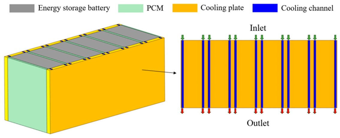
Figure 2 presents the establishment of a PCM-coupled liquid-cooling thermal management system. The battery module consists of six 280 Ah batteries, numbered 1 to 6 from left to right. The dimensions of the parallel-channel liquid cold plate are 15 mm × 204 mm × 456 mm, and the cross-sectional dimensions of a single flow channel are 6 mm × 10 mm. A 4 mm thick layer of PCM is inserted between adjacent batteries, and 2 mm thick PCM layers are added to the left side of Battery 1 and the right side of Battery 6. The PCM volume in the battery module is 0.85 L, corresponding to an added PCM mass of approximately 1.82 kg based on the PCM density listed in Table 1.

2.2. Governing Equation and Boundary Conditions

The governing equations of battery heat generation [44] are expressed as:
ρ b a t c p , b a t T b a t t = k T b a t + Q g e n
k = k i p 0 0 0 k t p 0 0 0 k i p
where Tbat, ρbat, and cp,bat are the temperature, the average density and the specific heat capacity of the battery; Qgen is the battery heat generation rate; and kip and ktp are the thermal conductivities in the in-plane and through-plane directions.
The battery heat generation can be computed by Bernardi’s mode [45]:
Q g e n = I U o U t I T U o T
where Uo and Ut mean the open-circuit voltage and the terminal voltage, and ∂Uo/∂T is the entropy coefficient. In this paper, the empirical equation is provided as follows:
Q g e n = A 1 t 6 + A 2 t 5 + A 3 t 4 + A 4 t 3 + A 5 t 2 + A 6 t + A 7
where A1A7 are polynomial coefficients fitted by the literature [46]. Table 2 lists the empirical constants in different discharge rates.
The governing equations of coolant flow [47] are outlined below:
v = 0
ρ w v t + v v = p + μ w 2 v
ρ w c p , w T w t + v T w = k w 2 T w
where cp,w, kw, ρw, Tw, and μw are the fluid specific heat capacity, thermal conductivity, temperature, density, and dynamic viscosity coefficient; and v is the flow velocity vector.
The convective heat transfer between the battery surface and air is given as follows:
k T b a t = h b a t a T b a t T a
where Ta is the ambient temperature, k is the battery thermal conductivity, T means the temperature gradient, and hbata is the convective heat transfer coefficient.
The heat transfer boundary between the cooling plate and the battery is calculated as follows:
k T b a t p = k p T b a t p
For PCM, the heat capacity cp is calculated as:
c p = 1 ρ k 1 ρ 1 c p , 1 + k 2 ρ 2 c p , 2 + L 1 2 α m T
where subscript 1 and 2 mean the solid and the liquid phases. The latent heat L is adopted as an additional term, assuming that the phase change happens between (TPCM − ΔTPCM/2) and (TPCM + ΔTPCM/2), where TPCM is the melting temperature, and ΔTPCM means the phase transition temperature range. In such a temperature range, the smoothed functions k1 and k2 are utilized to model the material phase. k1 = 1 and k2 = 0 if the temperature is lower than (TPCM − ΔTPCM/2); k1 = 0 and k2 = 1 if the temperature is higher than (TPCM + ΔTPCM/2); and k1 + k2 = 1 in any case, including the case that the temperature is between (TPCM − ΔTPCM/2) and (TPCM + ΔTPCM/2). In the phase change process calculation, k1 and k2 can be defined as:
k 1 = T P C M + Δ T P C M 2 T Δ T P C M
k 2 = T T P C M Δ T P C M 2 Δ T P C M
The mass fraction αPCM is calculated by Equation (12). The value of α is −1/2 before the transition and 1/2 after the transition. After the phase transition, this function becomes a fixed value.
α P C M = 1 2 k 2 ρ 2 k 1 ρ 1 k 1 ρ 1 + k 2 ρ 2
Moreover, the density ρPCM and heat conductivity λPCM are given as:
ρ P C M = k 1 ρ 1 + k 2 ρ 2
λ P C M = k 1 λ 1 + k 2 λ 2
The cooling water inlet is set as a mass-flow inlet, with a total inlet flow rate of 0.63 L/min and an inlet temperature of 25 °C. The cooling water outlet is set as a pressure outlet. The interfaces between different computational domains are set as coupled walls. The remaining surfaces exchange heat with the ambient air via natural convection, with an incoming flow temperature of 25 °C and a convective heat transfer coefficient of 5 W/(m2·K).
Unless otherwise stated, the maximum and minimum battery surface temperatures were extracted from all surfaces of the six battery cells and were defined as the global maximum and minimum values at each time step, respectively. The maximum temperature difference was calculated as the difference between these two values. The PCM liquid fraction was defined as the volume-averaged liquid fraction over all PCM domains. The temperature contours represent the battery surface temperature distributions at the end of the corresponding operating condition.
A three-dimensional transient fluid flow and heat transfer model was established and solved using ANSYS Fluent 2024R1. Pressure–velocity coupling was implemented using the SIMPLE algorithm. The pressure term was discretized using a second-order scheme, while a second-order implicit scheme was employed for temporal discretization. The time step was set to 10 s, and the maximum residual criterion was set to 1 × 10⁻⁴ for all equations. Under the investigated operating conditions, the PCM melting temperature was TPCM = 29.96 °C, while the phase transition temperature range used in the simulation was ΔTPCM = 2 °C.

2.3. Model Independence Verification

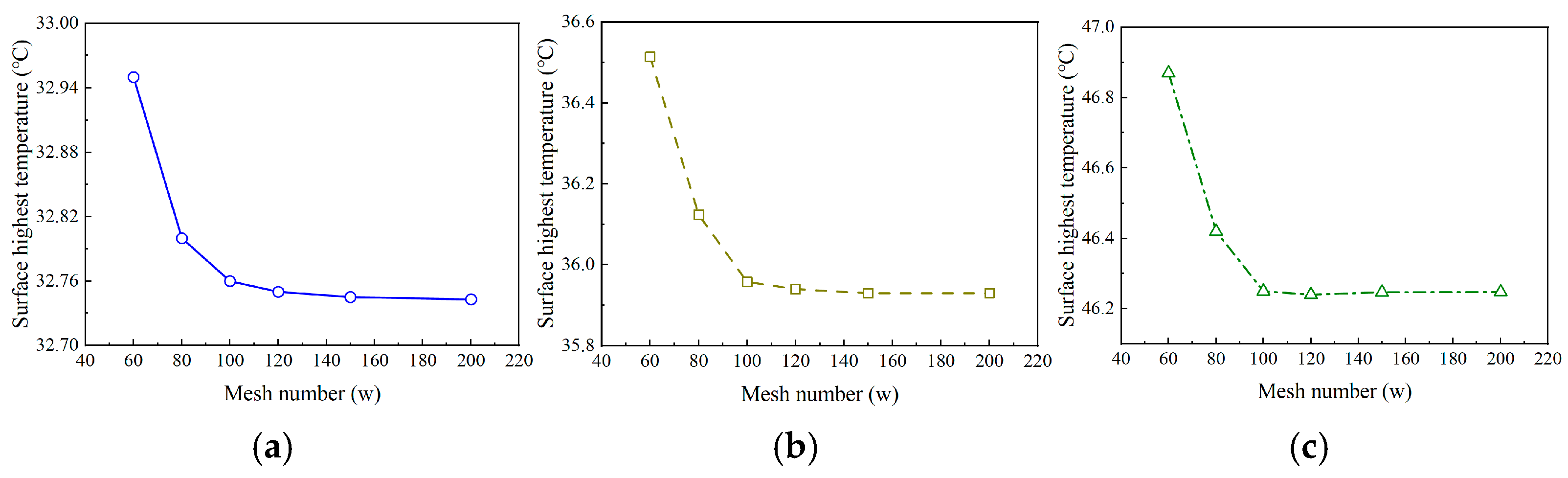
In this section, six different mesh sizes were generated, corresponding to element counts of 600,000, 800,000, 1,000,000, 1,200,000, 1,500,000, and 2,000,000. As illustrated in Figure 3, the simulation results become largely insensitive to the mesh count when the number of elements exceeds 1.2 million. Therefore, to strike a balance between computational accuracy and cost, a mesh containing 1.2 million elements was adopted for all subsequent simulations.

2.4. Model Validation

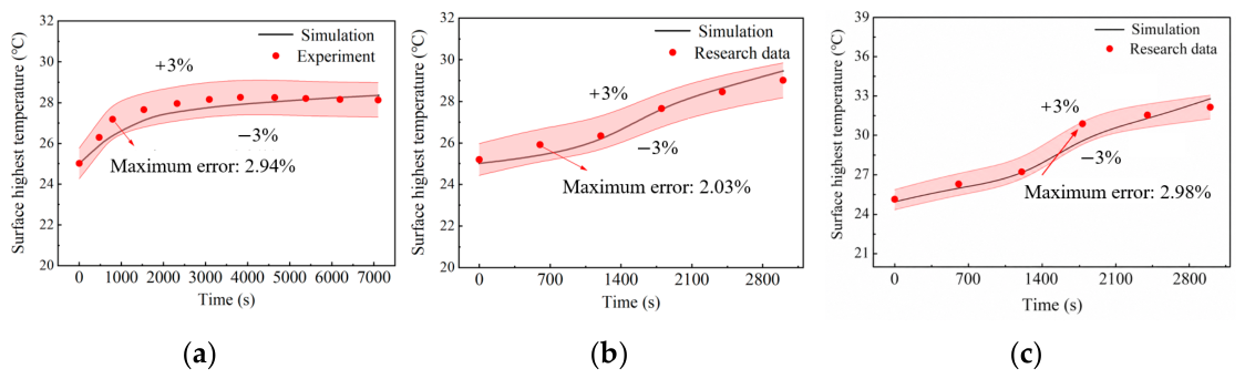
To verify the reliability of the simplified simulation model, a comparison with experimental data is required. Yu et al. [48] investigated a battery module composed of 280 Ah lithium iron phosphate batteries, examining the temperature performance of the battery module under 0.5C charge/discharge conditions through both simulation and experimentation. Moreover, the simulation model under 0.75C and 1C charge/discharge conditions are also compared with the research data [49]. A physical model identical to that used in the experiment was established, and the maximum temperature variation of the battery module was monitored. Figure 4 presents the comparison of the simulated and experimental battery surface highest temperature. The simulation results agree well with the experimental data, with a maximum relative error of less than 3% between the two.
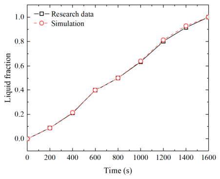
In addition, the PCM melting model is also validated based on the research data [50]. The maximum temperature variation of the battery module was monitored. Figure 5 shows the liquid fraction comparison of the simulated and experimental PCM melting. Similarly, the maximum liquid fraction error is less than 2%, denoting the effectiveness of the proposed PCM melting model.

3. Result and Discussion

3.1. Coupled Cooling Performance Analysis

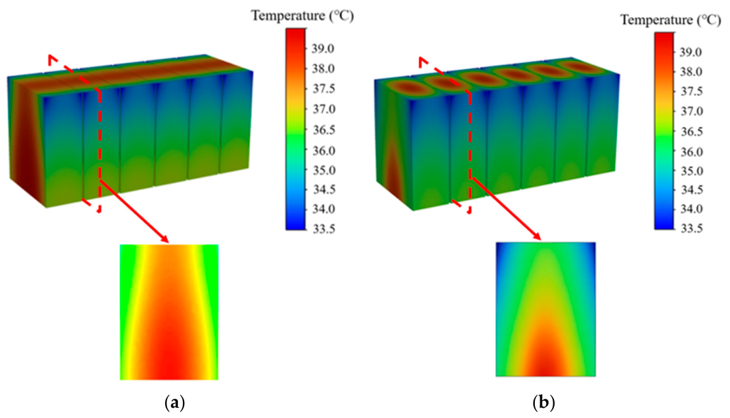
To evaluate the cooling performance of the PCM-coupled liquid-cooling thermal management system, the parallel-channel liquid cold-plate-cooling benchmark case is established for comparison. Figure 6 presents the temperature distribution of the batteries. It can be observed that the cooling effect of the parallel-channel liquid cold-plate-cooling configuration is favorable on the battery sides in direct contact with the cold plates but poor in the central region, resulting in an excessive temperature difference within a single battery. In contrast, for the PCM-coupled liquid-cooling configuration, the addition of PCM on the basis of cold plates placed on both sides improves the heat transfer conditions in the central region of the battery, leading to enhanced temperature uniformity within a single battery. To quantitatively analyze the proportion of high-temperature areas, we set 35 °C as the high-temperature limit. The proportion of high-temperature areas of the parallel-channel liquid cold-plate-cooling strategy and the PCM-coupled liquid-cooling strategy are 0.892 and 0.785. Such reduction indicates that the introduction of PCM can effectively improve the temperature uniformity across the battery surface, as the PCM absorbs a substantial amount of heat generated during the charging/discharging process through its latent heat, thereby mitigating localized hot spots and suppressing excessive temperature rise.
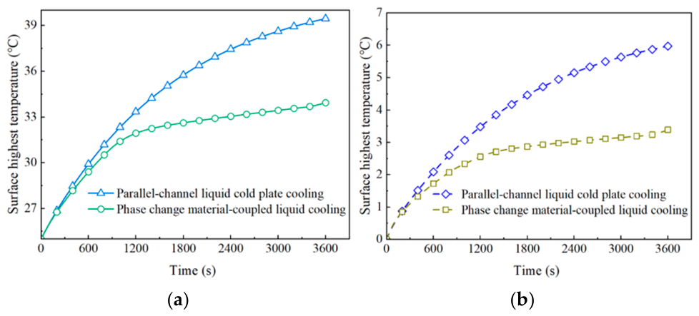
Figure 7a illustrates the variation of the battery surface highest temperature during the 1C discharge process of the battery module. It can be observed that for liquid cold-plate cooling alone, the battery temperature increases almost linearly at the initial stage. After 1200 s, the temperature rise rate gradually slows down, and the battery surface highest temperature reaches 39.4 °C. This is because at the beginning of discharge, the battery temperature is relatively low, resulting in a small temperature difference between the battery and the cold plate and thus a limited heat transfer rate. As the battery temperature rises, the temperature difference increases, leading to enhanced heat transfer and a reduced rate of temperature rise. For the PCM-coupled liquid-cooling thermal management method, the battery temperature rises rapidly. When reaching PCM’s melting point, the rate of temperature increase is suppressed due to the latent heat absorption during PCM melting. At the end of discharge, the battery surface highest temperature reaches 34.3 °C, corresponding to a temperature rise of only 9.3 °C. Compared with the parallel-channel liquid cold-plate cooling, the maximum temperature is reduced by 5.1 °C, demonstrating that the coupled cooling method effectively suppresses the maximum temperature.
Figure 7b presents the maximum temperature difference for the two thermal management systems. For parallel-channel liquid cold-plate cooling, the temperature difference gradually increases as discharge proceeds, reaching a maximum of 6 °C. This is attributed to the fact that the battery surfaces in direct contact with the cold plate maintain relatively low temperatures, whereas the surfaces far from the cold plate cannot be effectively cooled, leading to a large temperature difference that exceeds the allowable maximum temperature difference for energy storage batteries. For the PCM-coupled liquid-cooling method, the temperature difference increases rapidly at the initial stage. As the PCM gradually melts, the rate of temperature difference increases declines, and the maximum temperature difference is 3.38 °C. Compared with parallel-channel liquid cold-plate cooling, the maximum temperature difference is reduced by 2.62 °C, indicating that the addition of PCM can effectively suppress the rise in temperature difference within the battery module.

3.2. Operation and Physical Property Parameters Analysis

3.2.1. The Impact of Cooling Liquid

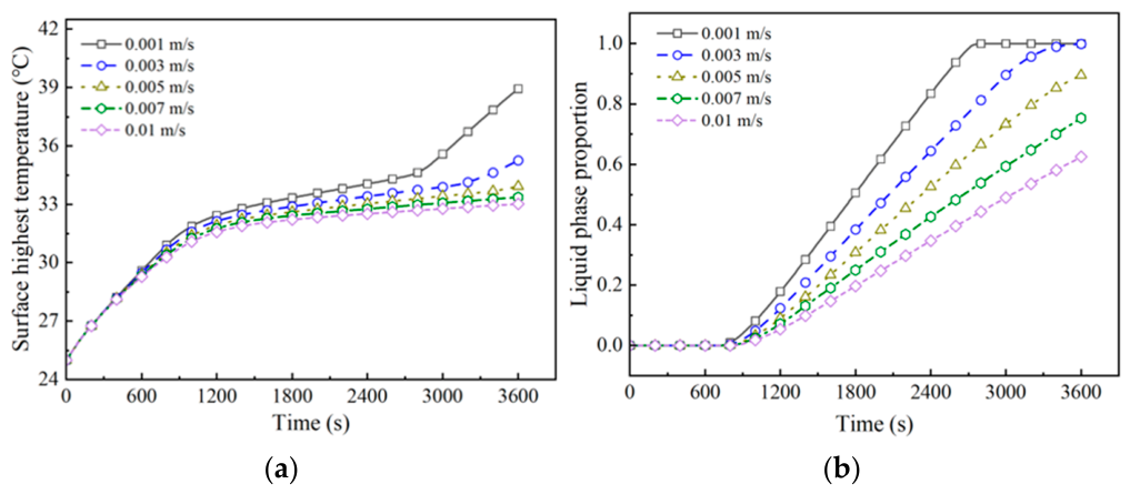
For the PCM-coupled liquid cooling, the cooling liquid inlet velocity not only affects the cooling performance but also plays a crucial role in the latent heat recovery of the PCM. Hence, five different velocities—0.001 m/s, 0.003 m/s, 0.005 m/s, 0.007 m/s, and 0.01 m/s—are selected in this section for impact analysis.
Figure 8a presents the battery surface highest temperature in different cooling liquid inlet velocities. Initially, the battery temperature rises rapidly. When reaching PCM’s melting point, the temperature increasing rate is suppressed, entering a plateau period. At 0.001 m/s and 0.003 m/s inlet velocities, the battery surface highest temperature rises rapidly again after the plateau period. This is attributed to the limited heat dissipation capacity of the cold plate at low inlet velocities, causing the phase change material to completely melt due to excessive heat absorption, leading to a subsequent sharp temperature rise. Correspondingly, Figure 8b shows the PCM’s liquid fraction and indicates that the liquid fraction reaches unity at the moment of sudden temperature increase. The surface highest temperature decreases with increasing inlet velocity, though the reduction diminishes progressively. As the velocity increases from 0.001 m/s to 0.003 m/s, the surface highest temperature decreases by 3.7 °C. As the velocity increases from 0.005 m/s to 0.007 m/s, the surface highest temperature drops by only 0.5 °C. Combined with the PCM liquid fraction variation, it is evident that at a 0.001 m/s inlet velocity, the low flow rate results in insufficient heat exchange. Even complete melting of the PCM fails to absorb the battery heat, leading to heat accumulation and an abnormal temperature rise.
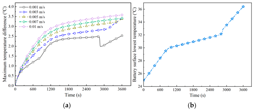
Figure 9a shows the maximum temperature difference. The maximum temperature difference increases as the inlet velocity increases. As presented in Figure 9b, the sudden drop in temperature difference is caused by PCM completely melting, which leads to a sudden increase in the minimum surface temperature of the battery and a sharp decrease in the temperature difference, followed by a trend toward dynamic equilibrium after a certain period. The subsequent sudden rise in temperature difference is attributed to the complete melting of the PCM, where the rapid increase in battery temperature results in an enlarged temperature difference.
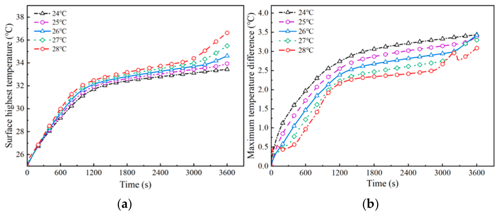
The cooling water inlet temperature also has impacts on the heat dissipation performance. Therefore, this section investigates the effects of five different cooling liquid inlet temperatures—24 °C, 25 °C, 26 °C, 27 °C, and 28 °C—on the battery surface highest temperature and maximum temperature difference. Figure 10a shows the variation of the battery surface highest temperature with different cooling liquid inlet temperatures; the surface highest temperature at the end of discharge continuously rises. When the inlet temperature increases from 24 °C to 28 °C, the surface highest temperature increases from 33.44 °C to 36.63 °C. If the cooling water inlet temperature exceeds 25 °C, the temperature rise rate increases again after the plateau period. Figure 10b presents the maximum temperature difference of the battery in different cooling liquid inlet temperatures. Higher inlet temperatures result in a smaller temperature difference before 3000 s. However, the battery temperature difference exhibits anomalous sudden increases and decreases after 3000 s. This is because the maximum temperature difference is jointly maintained by the cold plate and the PCM before 3000 s. A lower cooling water inlet temperature leads to a larger heat transfer rate between the cold plate and the battery, exerting a greater influence of the cold plate on the battery’s temperature field and thus leading to poorer temperature uniformity. After 3000 s, the complete melting of the PCM causes these anomalous variations in the temperature difference.

3.2.2. The Impact of PCM Thermophysical Properties

Aside from the operation parameters, PCM thermophysical property parameters, melting point and latent heat, also exert significant influence on the thermal management performance of PCM-coupled liquid cooling.
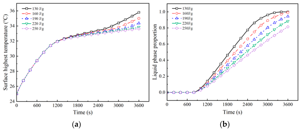
The latent heat of PCM is an important indicator of the temperature control capability of the thermal management system. Five different latent heat values—130 J/g, 160 J/g, 190 J/g, 220 J/g, and 250 J/g—are selected to investigate the effects of PCM latent heat on the battery thermal management performance.
Figure 11a presents the battery surface highest temperature at different PCM latent heat levels. It can be found that during the initial stage of discharge, the battery temperature rises rapidly. When the battery temperature reaches the PCM melting point, the temperature increasing rate decreases significantly, and the battery surface highest temperature decreases with PCM latent heat increasing. When the latent heat is below 220 J/g, the rate of temperature increase rises again after the temperature plateau period. As shown in Figure 11b, this phenomenon is attributed to the fact that as the PCM liquid fraction reaches 0.9, most of the PCM has completed the phase change, resulting in diminished heat storage capacity and consequently causing a rebound in battery temperature.
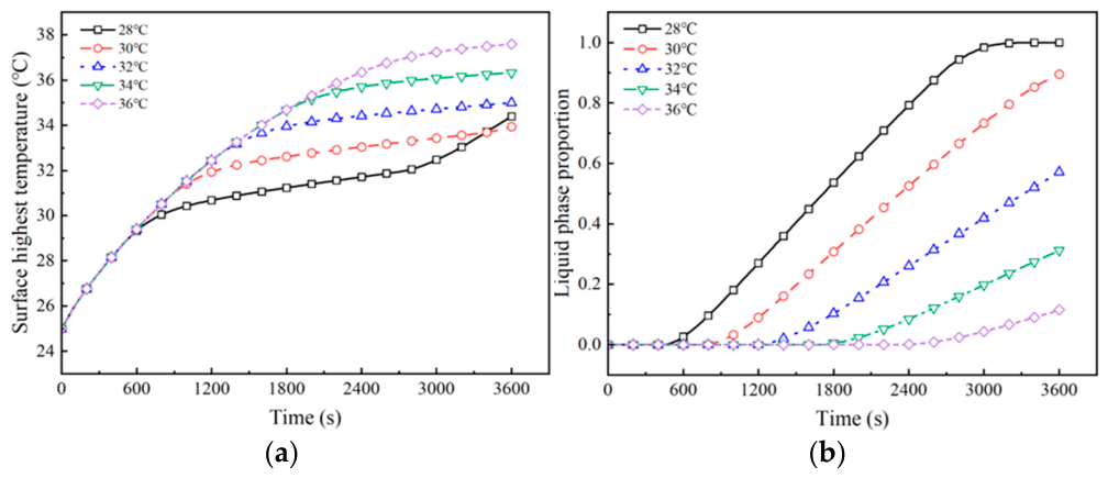
In addition to latent heat, the PCM melting point also plays an important role in battery management performance. Figure 12a presents the battery surface highest temperature at different melting points; the temperature rise nearly overlaps before 600 s. As the temperature increases, the temperature rise rate begins to decrease once the battery temperature reaches the PCM melting point after 600 s. The lower the melting point, the earlier the battery enters the slow temperature rise stage, thus achieving the lower the maximum battery temperature. However, as presented in Figure 12b, an excessively low melting point also causes the PCM to melt too early, leading to a rapid temperature increase during the later stage of discharge due to complete PCM melting. Therefore, the PCM melting point must be carefully selected; an inappropriate melting point can lead to an undesirable battery temperature rise.

3.2.3. Sensitivity Quantitative Analysis of Influencing Factors

To quantitatively evaluate the influence of these parameters on the thermal management system, a sensitivity analysis is performed. The sensitivity calculation of the above parameters is given as follows:
S A i = f max x i f min x i j = 1 n f max x j f min x j × 100
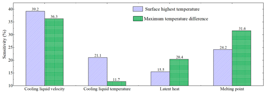
where xi and xj represent the key parameters, and n is the number of variables. The target variables are the battery surface highest temperature and the maximum temperature difference. fmax(xi) and fmin(xi) denote the maximum and minimum values of the relevant target variable, respectively. It should be noted that mean-variance normalization removes differences in units and numerical scales, while the sensitivity index in Equation (16) remains dependent on the selected parameter ranges. The adopted ranges represent the engineering conditions considered in this study, including a coolant velocity of 0.001–0.01 m/s and an inlet temperature of 24–28 °C. Accordingly, the sensitivity ranking in Figure 13 reflects the relative influence within these investigated ranges.
Figure 13 presents the sensitivity calculation results of the above four parameters with respect to the two target variables. Regarding the maximum temperature, the descending order of influence among the four parameters is: cooling liquid velocity (39.2%), melting point, cooling liquid temperature, and latent heat. For the maximum temperature difference, the ranking is: cooling liquid velocity (36.3%), melting point, latent heat, and cooling liquid temperature. Within the investigated parameter ranges, cooling liquid velocity exhibits the greatest relative influence on the two target variables. Therefore, increasing the cooling water velocity can effectively improve the cooling performance of the proposed battery thermal management system. Regarding the thermophysical properties of the PCM, the melting point exerts the largest influence, followed by the latent heat.

3.3. Operation Condition Adaptive Cooling Strategy Design Analysis

Considering that energy storage batteries do not operate at a fixed charge/discharge rate in practice, adaptive cooling strategies should be adopted for varying charge/discharge rates to minimize energy consumption while satisfying the thermal management demands of the battery. To comprehensively evaluate the cooling performance under different operating scenarios, the conventional liquid cold plate without PCM is employed as a benchmark and designated as the reference group in this section.

3.3.1. Low Charge/Discharge Rate Passive Cooling

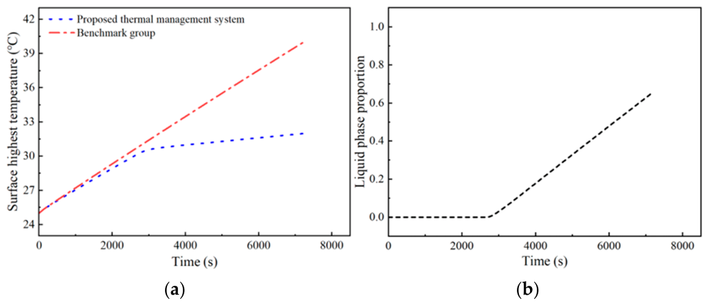
When the battery operates at a low rate (0.5C), liquid cooling is not activated, and only the PCM is used for passive system cooling. Figure 14a shows the battery surface highest temperature of the proposed thermal management system and the benchmark group during 0.5C discharge. Initially, the temperature rise rates of both groups are comparable. As the surface highest temperature reaches 30.1 °C, the PCM in the proposed thermal management system begins to melt and absorb heat, suppressing the temperature rise rate. At the end of discharge, the surface highest temperature of the proposed thermal management system is 31.98 °C, while that of the benchmark group is 39.95 °C, representing a difference of 7.97 °C. Figure 14b presents the PCM liquid fraction in the proposed thermal management system. The PCM starts melting at 2670 s, and the liquid fraction reaches 0.66, denoting that part of the latent heat remains unused.
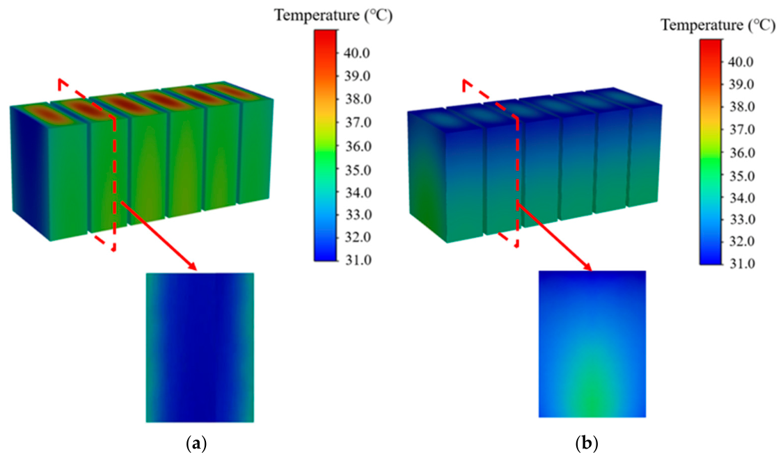
Figure 15 presents the temperature distribution of the benchmark group and the proposed thermal management system. For the benchmark group, the battery surface highest temperature distribution is 39.95 °C. Owing to natural convection cooling at the top of the battery, the minimum surface temperature appears at the top, while the maximum temperature appears at the bottom adiabatic surface. For the coupled thermal management system, the battery surface highest temperature is 31.98 °C. This indicates that utilizing only the latent heat of the PCM is sufficient to achieve effective battery cooling under low charge/discharge rates.

3.3.2. High Charge/Discharge Rate Delayed Cooling

When the battery operates continuously at a medium rate (0.75C), passive cooling leads to excessive battery temperature rise in the later stage due to complete PCM melting. Conversely, adopting liquid cooling in advance will result in inefficient utilization of PCM latent heat, thus increasing the system energy consumption. Therefore, this section proposes a delayed cooling strategy, in which liquid cooling is activated when the maximum battery temperature reaches 35 °C and deactivated when the battery temperature drops to 28 °C. These thresholds are engineering-based rather than formally optimized and are selected with reference to the recommended operating temperature range in Ref. [42], which identifies 25–40 °C as the optimal operating temperature range for a lithium-ion battery. Therefore, the activation at 35 °C reserves a 5 °C margin below the upper limit to account for thermal inertia and prevent the battery from exceeding 40 °C, while the deactivation at 28 °C provides a 3 °C hysteresis above the lower limit to avoid frequent on–off cycling and ensure system stability. This approach satisfies the battery cooling requirements while improving the utilization of PCM latent heat while reducing the system energy consumption.
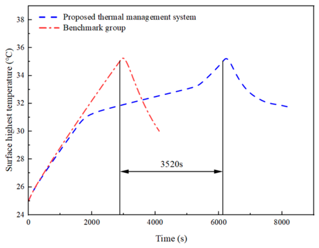
This study focuses on the overall thermal response of the thermal management system under continuous cyclic operation. To emphasize the heat accumulation and cooling response during the cycling process, the effects of SOC variation and transient differences in heat generation between the charging and discharging stages are neglected. The charging and discharging processes are therefore represented as periodic constant thermal loads, with the same equivalent heat generation rate applied throughout the entire cycle [51,52]. Figure 16 shows the maximum battery temperature of the coupled thermal management system and the benchmark group during 0.75C discharge. As discharge proceeds, the maximum temperature continuously rises. When the maximum temperature reaches 31 °C, the PCM melting in the coupled thermal management system slows down the temperature rise rate. The time for the benchmark group to reach 35 °C is 2870 s, while that for the coupled thermal management system is 6390 s, representing a delay of 3520 s. Liquid cooling is activated when the maximum temperature reaches 35 °C, with a cooling water inlet velocity of 0.01 m/s and an inlet temperature of 20 °C. It should be underscored that the benchmark group also adopts the same liquid-cooling setting, for fair comparison. In the present analysis, the coolant inlet temperature of 20 °C is prescribed as a boundary condition and is assumed to be supplied by an external temperature-controlled loop; therefore, the refrigeration energy required for coolant conditioning is outside the system boundary considered in this study. Owing to thermal inertia, the maximum battery temperature does not decrease immediately upon the introduction of cooling water but instead continues to rise slightly to 35.2 °C.
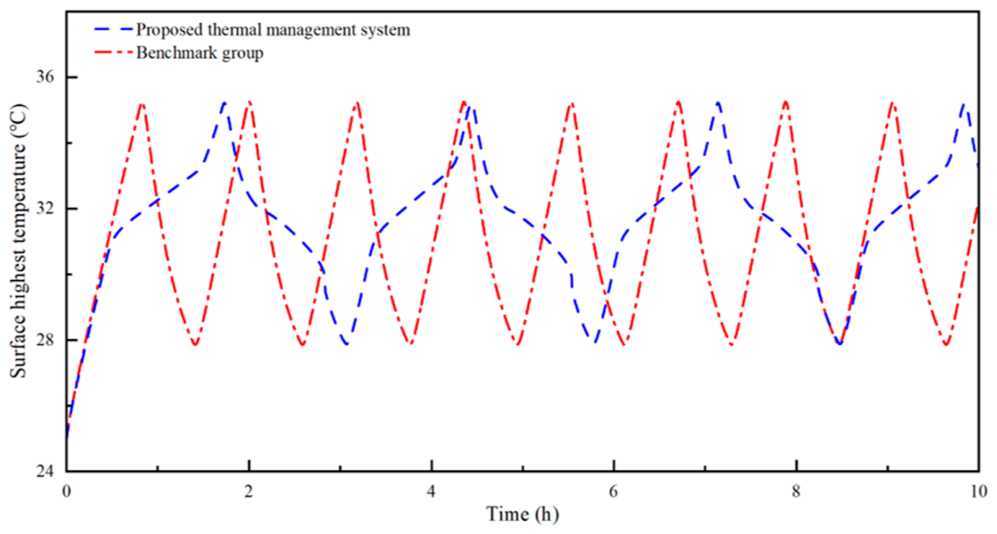
To further investigate the impact of the delayed cooling strategy on the system energy consumption, the liquid-cooling operation times of the coupled thermal management system and the benchmark group during 10 h of continuous battery operation are compared. Figure 17 shows the maximum temperature for both configurations. To maintain the battery temperature between 28 °C and 35 °C, the liquid-cooling system undergoes repeated start-up and shutdown cycles over the 10 h period. The benchmark group requires eight cooling cycles during the 10 h operation, while the coupled thermal management system requires only three cooling cycles. Since liquid cooling simultaneously cools both the battery and the PCM, the cooling cycle of the coupled thermal management system is longer than that of the benchmark group: the cooling cycle of the benchmark group is 1630 s, whereas that of the coupled thermal management system is 4800 s. However, the total liquid-cooling runtime of the coupled thermal management system is shorter than that of the benchmark group. The coupled thermal management system has a total liquid-cooling time of 15,000 s, while that of the benchmark group is 16,720 s. During 10 h of continuous battery operation, the coupled thermal management system reduces the liquid-cooling runtime by a total of 1720 s. To provide a quantitative estimate of the pump energy savings, given a typical pump configuration with a flow velocity of 0.01 m/s, the hydraulic power is approximately 5.0 W. Assume the pump efficiency is 85%; the corresponding electrical power consumption is approximately 5.88 W. The proposed strategy reduces the pump runtime by 1720 s compared with the baseline. Accordingly, the estimated pump electrical energy saving is approximately 2.8 Wh compared with the benchmark group.

4. Conclusions

This paper presents a PCM-coupled liquid-cooling thermal management system with an operation condition adaptive control strategy for energy storage batteries. The coupled cooling performance, the effects of operating parameters and PCM thermophysical properties, and the adaptive cooling strategy under different charge/discharge rates are systematically investigated. The conclusions are as follows:
(1) PCM and liquid cooling provide complementary thermal regulation functions. PCM buffers transient battery thermal loads, while liquid cooling removes the accumulated heat. Their coordinated use improves temperature uniformity, demonstrating the engineering benefit of combining passive thermal buffering with active heat removal.
(2) The thermal performance of the coupled system is jointly governed by coolant operating parameters and PCM thermophysical properties. Effective system design therefore requires appropriate matching of coolant conditions and PCM properties to the battery thermal load, thereby coordinating the heat dissipation and heat storage capacities.
(3) The operation rate-dependent coordinated strategy switches between passive PCM cooling and delayed active liquid cooling according to the battery thermal demand. This reduces unnecessary liquid-cooling operation while maintaining effective temperature control, indicating its practical potential for improving energy efficiency and adaptability under variable operating conditions.
It should be noted that this study was conducted under a constant ambient temperature, stable coolant inlet conditions, uniform volumetric heat generation, equivalent charging/discharging thermal loads, and constant PCM thermophysical properties. Variations in actual operating boundaries, differences in heat generation among cells, transient heat generation characteristics, and long-term PCM degradation were not considered. These factors may affect the battery temperature distribution, PCM phase transition process, and liquid-cooling activation behavior. Therefore, the present results mainly reflect the relative performance of different thermal management schemes under the specified conditions. Future research will incorporate realistic operating boundaries and non-uniform transient heat generation models, conduct long-term PCM cycling experiments, and introduce the resulting property evolution behavior into the numerical model to further evaluate the engineering applicability and long-term reliability of the system.

Author Contributions

Conceptualization, X.W. and G.L.; methodology, F.Q. and L.G.; software, Q.C. and Y.L.; validation, W.Y.; formal analysis, W.Y. and L.G.; investigation, Y.L. and F.Q.; resources, X.W. and G.L.; data curation, F.Q., L.G. and W.Y.; writing—original draft preparation, X.W. and Y.L.; writing—review and editing, G.L.; visualization, Y.L. and Q.C.; supervision, G.L.; project administration, W.Y.; funding acquisition, G.L. All authors have read and agreed to the published version of the manuscript.

Funding

This research was funded by the Fundamental Research Funds for the Central Universities (No. 202JC005).

Data Availability Statement

Data is contained within the article.

Conflicts of Interest

Authors Xinyu Wang, Fang Qi, Wei Yue, Lei Gao were employed by the company Inner Mongolia Huadian Hydrogen Energy Technology Co., Ltd. The remaining authors declare that the research was conducted in the absence of any commercial or financial relationships that could be construed as a potential conflict of interest.

Abbreviations

The following abbreviations and symbols are used in this manuscript:
cp,batBattery-specific heat capacity
TbatBattery temperature
ρbatBattery average density
QgenBattery volumetric heat generation rate
kThermal conductivity matrix
ktpThermal conductivity in the through-plane direction
kipThermal conductivity in the in-plane direction
UtTerminal voltage
UoOpen-circuit voltage
kwWater thermal conductivity
cp,wSpecific heat capacity of water
TwWater temperature
vWater flow velocity vector
TaAmbient temperature
TTemperature gradient
∂Uo/∂TEntropy coefficient
A1A7Polynomial coefficients
ρwWater density
μwWater dynamic viscosity coefficient
TPCMPhase transition temperature
ΔTPCMPhase transition temperature range
cp,iSpecific heat

References

  1. Pokhriyal, A.; Rueda-García, D.; Gómez-Romero, P. To flow or not to flow. A perspective on large-scale stationary electrochemical energy storage. Sustain. Energy Fuels 2023, 7, 5473–5482. [Google Scholar] [CrossRef] [Scilit]
  2. Deguenon, L.; Yamegueu, D.; Gomna, A. Overcoming the challenges of integrating variable renewable energy to the grid: A comprehensive review of electrochemical battery storage systems. J. Power Sources 2023, 580, 233343. [Google Scholar] [CrossRef] [Scilit]
  3. Wang, J.; Zhang, Y.; Li, X.; Liu, H.; Zhao, Q. Review on influence factors and prevention control technologies of lithium-ion battery energy storage safety. J. Energy Storage 2023, 72, 108389. [Google Scholar] [CrossRef] [Scilit]
  4. Feng, X.; Ouyang, M.; Liu, X.; Lu, L.; Xia, Y.; He, X. Thermal runaway mechanism and prevention strategies of lithium-ion batteries: Recent advances and future perspectives. eTransportation 2024, 19, 100319. [Google Scholar]
  5. Nuroldayeva, G.; Serik, Y.; Adair, D. State of health estimation methods for lithium-ion batteries. Int. J. Energy Res. 2023, 2023, 4297545. [Google Scholar] [CrossRef] [Scilit]
  6. Jiang, T.; Shen, D.; Zhang, Z.; Liu, H.; Zhao, G.; Wang, Y.; Tan, S.; Luo, R.; Chen, W. Battery technologies for grid-scale energy storage. Nat. Rev. Clean Technol. 2025, 1, 474–492. [Google Scholar] [CrossRef] [Scilit]
  7. Khan, M.; Rahman, S.; Ahmed, T.; Alotaibi, M.A. Integrated energy storage systems for enhanced grid efficiency: A comprehensive review of technologies and applications. Energies 2025, 18, 1848. [Google Scholar] [CrossRef] [Scilit]
  8. Zhang, H.; Li, Y.; Wang, X.; Chen, Z. Electrochemical storage systems for renewable energy integration: A comprehensive review of battery technologies and grid-scale applications. J. Power Sources 2025, 641, 236832. [Google Scholar] [CrossRef] [Scilit]
  9. Liu, Y.; Chen, J.; Zhao, H.; Wang, P. Data-driven optimization of lithium battery energy storage for grid stability and renewable energy integration. Int. J. Hydrogen Energy 2025, 127, 646–654. [Google Scholar] [CrossRef] [Scilit]
  10. Yang, Z.; Kong, D.; Chen, Z.; Zhang, Z.; Du, D.; Zhu, Z. A data-driven battery energy storage regulation approach integrating machine learning forecasting models for enhancing building energy flexibility-A case study of a net-zero carbon building in China. Buildings 2025, 15, 3611. [Google Scholar] [CrossRef] [Scilit]
  11. Lin, H.; Yan, Z.; Meng, X.; Xie, D. Detection-free neural DC-link voltage correction for cyber-resilient solid-state transformers: A dual-stream denoising scheme. IEEE Trans. Power Electron. 2026. early access. [Google Scholar] [CrossRef] [Scilit]
  12. Mallick, S.; Gayen, D. Thermal behaviour and thermal runaway propagation in lithium-ion battery systems—A critical review. J. Energy Storage 2023, 62, 106894. [Google Scholar] [CrossRef] [Scilit]
  13. Xu, L.; Wang, S.; Xi, L.; Li, Y.; Gao, J. A review of thermal management and heat transfer of lithium-ion batteries. Energies 2024, 17, 3873. [Google Scholar] [CrossRef] [Scilit]
  14. Wang, Y.; Wang, Q.; Zhao, J.; Li, H. Recent progress in battery thermal management technologies for lithium-ion batteries. Energy Storage Mater. 2024, 67, 103302. [Google Scholar]
  15. Li, Y.; Zhang, X.; Wang, J.; Zhao, H. A comprehensive review on thermal runaway model of a lithium-ion battery: Mechanism, thermal, mechanical, propagation, gas venting and combustion. Renew. Energy 2024, 229, 120762. [Google Scholar] [CrossRef] [Scilit]
  16. Zhang, Y.; Wang, C.; Chen, M.; Li, J. A systematic review and comparison of liquid-based cooling system for lithium-ion batteries. Energy Rep. 2023, 17, 100242. [Google Scholar] [CrossRef] [Scilit]
  17. Liu, Z.; Yang, S.; He, F.; Zhang, T. Advances in liquid-cooled battery thermal management systems: Design strategies and performance evaluation. Appl. Therm. Eng. 2025, 269, 125938. [Google Scholar]
  18. Chen, J.; Li, X.; Wang, H.; Zhao, Y. Numerical and experimental investigations of liquid cooling technologies for lithium-ion battery thermal management: A review. Renew. Sustain. Energy Rev. 2025, 201, 115102. [Google Scholar]
  19. Xu, Z.; Li, J.; Wang, P.; Chen, H. A review of battery thermal management systems using liquid cooling and PCM. J. Energy Storage 2024, 76, 109836. [Google Scholar] [CrossRef] [Scilit]
  20. Choi, H.; Lee, H.; Han, U.; Jung, J.; Kim, J. Comparative evaluation of liquid cooling-based battery thermal management systems: Fin cooling, PCM cooling, and intercell cooling. Int. J. Energy Res. 2024, 2024, 5395508. [Google Scholar] [CrossRef] [Scilit]
  21. Li, H.; Chen, L.; Zuo, H.; Zhang, B.; Jia, G. Performance enhancement of a battery thermal management system using novel liquid cold plates with micro-channel featuring pin fins. Energy 2024, 301, 132763. [Google Scholar] [CrossRef] [Scilit]
  22. Wu, C.; Sun, Y.; Tang, H.; Zhang, S.; Yuan, W.; Liu, W.; Zhu, L.; Tang, Y. A review on the liquid cooling thermal management system of lithium-ion batteries. Appl. Energy 2024, 375, 124173. [Google Scholar] [CrossRef] [Scilit]
  23. Niu, Z.H.; Pang, K.G.; Pang, B.B.; Wang, S. Orthogonal experimental-based thermal management design and simulation optimization of a liquid-cooled battery module. Sci. Rep. 2025, 15, 33442. [Google Scholar] [CrossRef] [Scilit]
  24. Zhang, X.; Li, Y.; Wang, H. A state-of-the-art review on numerical investigations of liquid-cooled battery thermal management systems for lithium-ion batteries of electric vehicles. J. Energy Storage 2024, 101, 113844. [Google Scholar] [CrossRef] [Scilit]
  25. Ortiz, Y.; Arévalo, P.; Peña, D.; Jurado, F. Recent advances in thermal management strategies for lithium-ion batteries: A comprehensive review. Batteries 2024, 10, 83. [Google Scholar] [CrossRef] [Scilit]
  26. Shi, H.; Cheng, M.; Feng, Y.; Qiu, C.; Song, C.; Yuan, N.; Kang, C.; Yang, K.; Yuan, J.; Li, Y. Thermal management techniques for lithium-ion batteries based on phase change materials: A systematic review and prospective recommendations. Energies 2023, 16, 876. [Google Scholar] [CrossRef] [Scilit]
  27. Zhang, Y.; Wang, J.; Liu, H.; Zhao, X. Progress of research on phase change energy storage materials in their thermal conductivity. J. Energy Storage 2023, 61, 106772. [Google Scholar] [CrossRef] [Scilit]
  28. Mousavi, S.; Al-Hallaj, S.; Jaguemont, J.; Dubé, Y. Phase change materials for lithium-ion battery thermal management systems: A review. J. Energy Storage 2024, 80, 110259. [Google Scholar] [CrossRef] [Scilit]
  29. Wang, Y.; Zhao, L.; Zhan, W.; Chen, Y.; Chen, M. Flame retardant composite phase change materials with MXene for lithium-ion battery thermal management systems. J. Energy Storage 2024, 86, 111293. [Google Scholar] [CrossRef] [Scilit]
  30. Dong, Y.; Ma, X.; Wang, C.; Xu, Y. Research on experimental and simulated temperature control performance of power batteries based on composite phase change materials. World Electr. Veh. J. 2024, 15, 302. [Google Scholar] [CrossRef] [Scilit]
  31. Yuan, X.; Zhang, Y.; Wang, H.; Li, Z.; Zhao, J. Hybrid battery thermal management systems based on phase transition processes: A comprehensive review. J. Energy Storage 2024, 86, 111227. [Google Scholar] [CrossRef] [Scilit]
  32. Sen, S.; Mahdi, J.M.; Talebizadehsardari, P.; La Rocca, A.; Cairns, A. Enhanced thermal management of lithium-ion pouch cells via hybrid approach of phase change material-liquid cooling. Int. Commun. Heat Mass Transf. 2025, 170, 108997. [Google Scholar] [CrossRef] [Scilit]
  33. Kang, Z.; Wang, X.; Yin, R.; Xu, L.; Wu, J.; Wang, S.; Peng, Q. Optimizing of coupled phase change materials and liquid cooling thermal management for Li-ion battery pack. Appl. Therm. Eng. 2025, 273, 126508. [Google Scholar] [CrossRef] [Scilit]
  34. Kim, Y.J.; Lee, D.H.; Park, S.H. Thermal performance enhancement of hybrid liquid cooling and phase change material systems for lithium-ion battery packs. Appl. Therm. Eng. 2025, 271, 126171. [Google Scholar] [CrossRef] [Scilit]
  35. Kumar, A.; Dewangan, A.K.; Yadav, A.K. A state-of-the-art review on modelling and simulation of battery thermal management system using phase change material and liquid cooling: Enhancing performance, sustainability, and future research needs. J. Energy Storage 2025, 133, 117978. [Google Scholar] [CrossRef] [Scilit]
  36. Xu, Q.; Xie, Y.; Huang, H.; Lin, X.M.; Li, L.; Wang, X.; Zheng, K. Parametric studies and design recommendations for a novel hybrid battery thermal management system with ultrathin PCM layers between liquid cooling channels and batteries. Energy 2025, 337, 137159. [Google Scholar] [CrossRef] [Scilit]
  37. Balasubramanian, D.; Venugopal, I.P.; Subramanian, M.; Raja, V.; Kale, U.; Matijošius, J. Study on the battery thermal management system for cylindrical lithium-ion battery with nano-doped phase change material and liquid cooling. Sci. Rep. 2025, 15, 24053. [Google Scholar] [CrossRef] [Scilit] [PubMed]
  38. Hyun, S.W.; Kim, J.H.; Shin, D.H. Hybrid PCM–Liquid cooling system with optimized channel design for enhanced thermal management of lithium-ion batteries. Energies 2025, 18, 4996. [Google Scholar] [CrossRef] [Scilit]
  39. Xiao, J.; Min, H.; Jiang, H.; Zhang, Z.; Sun, W.; Cao, Q. A novel hybrid battery thermal management integrating phase change material and micro-channel liquid cooling. Appl. Therm. Eng. 2025, 274, 126721. [Google Scholar] [CrossRef] [Scilit]
  40. Ma, C.; Deng, Y.; Lu, Y.; Zhang, Y.; Wu, X. Dimensionless-index framework for delayed cooling coordination in PCM–liquid hybrid battery thermal management over wide ambient temperatures. Energy 2026, 355, 141187. [Google Scholar] [CrossRef] [Scilit]
  41. He, T.; Mi, H.; Wang, W.; He, Y.; Zhi, M.; Lyu, Y.; Cai, Q. A systematic investigation of thermal and electrochemical behaviour of a cylindrical lithium-ion battery during charge and discharge processes. Energy 2025, 334, 137014. [Google Scholar] [CrossRef] [Scilit]
  42. Ferreira, P.; Tang, S.X. Investigating thermal dynamics in cylindrical Li-ion batteries across varied temperatures based on electrochemical principles. Sci. Rep. 2025, 15, 30830. [Google Scholar] [CrossRef] [Scilit] [PubMed]
  43. Zhou, Y.; Li, M.; Wang, K.; Xu, C. Heat generation characteristics of lithium-ion batteries under dynamic operating conditions: A review. J. Energy Storage 2025, 118, 115947. [Google Scholar]
  44. Lyu, C.; Song, Y.K.; Yang, D.Z.; Wang, W.T.; Ge, Y.M.; Wang, L.X. Online prediction for heat generation rate and temperature of lithium-ion battery using multi-step-ahead extended Kalman filtering. Appl. Therm. Eng. 2023, 231, 120890. [Google Scholar] [CrossRef] [Scilit]
  45. Powar, K.P.; Patil, S.D. Analysis of discharge behaviour and heat generation at in the 18650 lithium ion battery cell. Jordan J. Mech. Ind. Eng. 2025, 19, 500. [Google Scholar] [CrossRef] [Scilit] [PubMed]
  46. Zhao, Y.; Gao, W.; Mao, C.; Yi, Z.; Qian, Y.; Wang, Q.; Zhang, X. Numerical Investigation of Cooling Liquid Effects on Thermal Performance and Uniformity of an Immersion-Cooled Lithium-Ion Battery Module. Appl. Sci. 2026, 16, 3478. [Google Scholar] [CrossRef] [Scilit]
  47. Meng, J.H.; Ma, C.Y.; Liu, Y.; Wang, L.; Xu, C.; Lu, G. Artificial neural network (ANN) based prediction and optimization of battery thermal management for non-uniform flow channel design. J. Energy Storage 2025, 111, 115404. [Google Scholar] [CrossRef] [Scilit]
  48. Yu, L.Y.; Li, Z.X.; Dong, S.Q.; Li, J.J.; Li, P.H. Analysis of heat dissipation performance of battery pack based on CFD simulation. New Technol. New Process 2024, 54–61. [Google Scholar] [CrossRef]
  49. Wang, X.X.; Zhang, Y.J.; Deng, Y.L.; Yuan, Y.N.; Zhang, F.B.; Lv, S.S.; Zhu, Y.; Ni, H.J. Effects of Different Charging Currents and Temperatures on the Voltage Plateau Behavior of Li-Ion Batteries. Batteries 2023, 9, 42. [Google Scholar] [CrossRef] [Scilit]
  50. Abdellatif, H.E.; Belaadi, A.; Arshad, A.; Chai, B.X.; Alshaikh, I.M.H.; Ghernaout, D. Advancing Thermal Energy Storage: Unravelling the Optimal Orientation of Annular Phase Change Material Containers within the Tank. Case Stud. Therm. Eng. 2025, 68, 105931. [Google Scholar] [CrossRef] [Scilit]
  51. Kim, T.J.; Youn, B.D.; Kim, H.J. Battery Pack Temperature Estimation Model for EVs and Its Semi-transient Case Study. Chem. Eng. Trans. 2013, 33, 955–960. [Google Scholar]
  52. Martellucci, L.; Capata, R. Optimization of an Innovative Cooling System for Motorsport Application. Int. J. Thermofluids 2024, 24, 100944. [Google Scholar] [CrossRef] [Scilit]
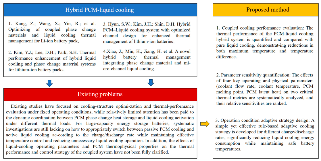
Figure 1. The knowledge gap between the proposed method and existing studies [33,35,38,39].
Electronics 15 04261 g001
Figure 2. The geometry structure of PCM-coupled liquid-cooling thermal management system.
Electronics 15 04261 g002
Figure 3. Grid independence verification result: (a) 0.5C; (b) 0.75C; (c) 1C.
Electronics 15 04261 g003
Figure 4. Battery model validation result: (a) 0.5C; (b) 0.75C; (c) 1C.
Electronics 15 04261 g004
Figure 5. PCM melting model validation.
Electronics 15 04261 g005
Figure 6. Temperature distribution of two cooling configurations: (a) parallel-channel liquid cold-plate cooling; (b) phase change material-coupled liquid cooling.
Electronics 15 04261 g006
Figure 7. Cooling performance of two cooling configuration: (a) surface highest temperature; (b) maximum temperature difference.
Electronics 15 04261 g007
Figure 8. (a) Battery surface highest temperature; (b) Liquid phase proportion in different cooling liquid inlet velocities.
Electronics 15 04261 g008
Figure 9. (a) Maximum temperature difference; (b) Battery surface lowest temperature in different cooling liquid inlet velocities.
Electronics 15 04261 g009
Figure 10. (a) Battery surface highest temperature; (b) Maximum temperature difference in different cooling liquid inlet temperatures.
Electronics 15 04261 g010
Figure 11. (a) Battery surface highest temperature; (b) Liquid phase proportion in different PCM latent heat.
Electronics 15 04261 g011
Figure 12. (a) Battery surface highest temperature; (b) Liquid phase proportion in different PCM melting point.
Electronics 15 04261 g012
Figure 13. Sensitivity quantitative analysis results.
Electronics 15 04261 g013
Figure 14. Passive cooling result: (a) Surface highest temperature comparison; (b) Liquid phase proportion.
Electronics 15 04261 g014
Figure 15. Temperature distribution of (a) benchmark group and (b) proposed thermal management system at the end of 0.5C discharge.
Electronics 15 04261 g015
Figure 16. Battery surface highest temperature comparison.
Electronics 15 04261 g016
Figure 17. Variation of maximum temperature comparison during 10 h operation.
Electronics 15 04261 g017
Table 1. Material physical properties.
Specific Heat Capacity
(J/(kg K))
Density
(kg/m3)
Thermal Conductivity
(W/(m K))
Melting Point (°C)Phase Change Latent Heat (J/g)
Cooling plate9712719202.4//
Battery8712062kY = kZ = 22, kX = 4//
Coolant4182998.20.6//
Paraffin/expanded PCM309021402.5229.96214.5
Table 2. Heat generation coefficients at different C-rates.
Discharge RateA1A2A3A4A5A6A7
0.5C6.607 × 10−18−1.438 × 10−131.160 × 10⁻⁹−4.143 × 10−65.861 × 10−3−8.664 × 10−11.589 × 103
0.75C1.310 × 10−16−1.856 × 10−128.963 × 10⁻⁹−1.252 × 10⁻⁵−2.369 × 10−26.588 × 1010
1C9.126 × 10−16−9.992 × 10−124.076 × 10⁻⁸−7.463 × 10−55.749 × 10−2−1.175 × 1011.651 × 104
Disclaimer/Publisher’s Note: The statements, opinions and data contained in all publications are solely those of the individual author(s) and contributor(s) and not of MDPI and/or the editor(s). MDPI and/or the editor(s) disclaim responsibility for any injury to people or property resulting from any ideas, methods, instructions or products referred to in the content.