1. Introduction
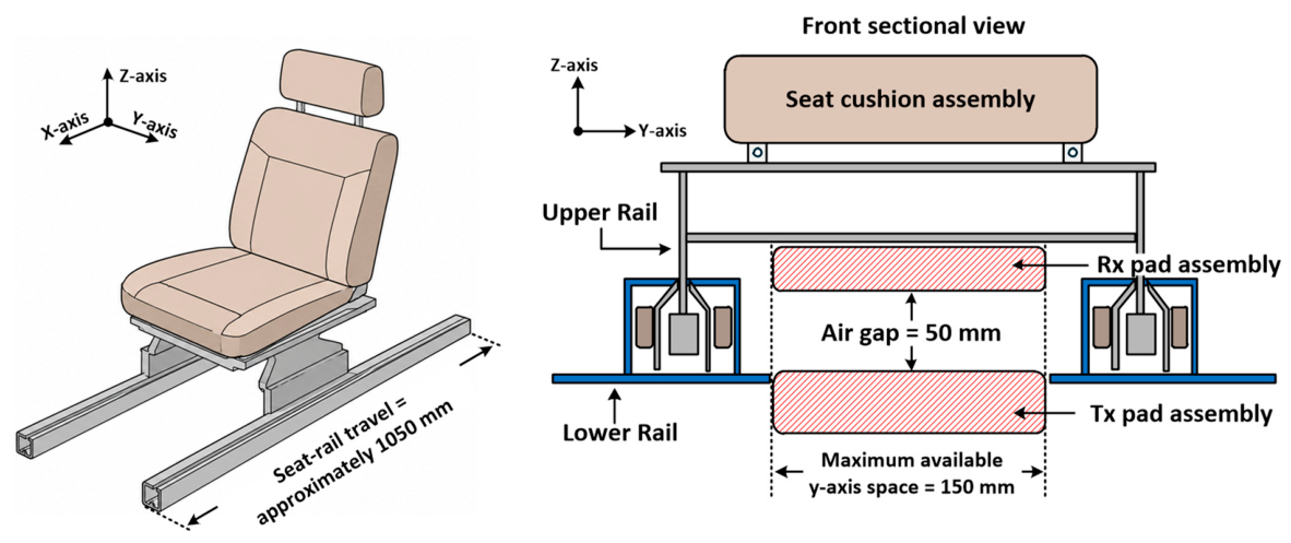
As vehicle electrification and autonomous-driving technologies advance, automotive seats are increasingly required to accommodate electrical loads such as heating, ventilation, and massage systems in addition to conventional position-adjustment actuators. These loads are typically supplied through wiring harnesses connected to the vehicle power source. However, repeated forward–backward movement and rotation of the seat subject the wiring to continuous bending and friction. This can cause insulation abrasion, mechanical fatigue, and conductor failure over long-term operation. Wiring harnesses also restrict the available range of seat motion, complicate mechanical design, and require dedicated routing space.
Wireless power transfer (WPT) provides an alternative means of supplying power between a stationary vehicle structure and a movable seat assembly without direct electrical contact. Recent reviews have summarized EV-oriented WPT technologies, including inductive couplers, compensation networks, misalignment, control, and safety considerations [
1,
2]. Capacitive WPT has also been reviewed as a complementary approach with distinct coupler, electric-field, and compensation-network requirements [
3,
4]. The present study focuses on magnetically coupled inductive power transfer (IPT) for an automotive power seat.
An early vehicle-seat-related study transferred power through a military vehicle seat to electronic equipment carried by the occupant, demonstrating the feasibility of WPT around a vehicle seat [
5]. However, that system was intended for power transfer through a stationary seat and did not address the wide rail-direction displacement required for a movable automotive power seat. More recently, an automotive power-seat WPT system was proposed in which the transmitter and receiver coils were embedded within the seat rail and the magnetic-core structure was optimized to reduce leakage magnetic fields [
6]. Because the magnetic coupler was installed inside the rail, that approach requires a rail structure capable of accommodating the coils and magnetic cores. In contrast, the present study considers repeated transmitter segments installed alongside the rail without requiring modification of the internal rail structure.
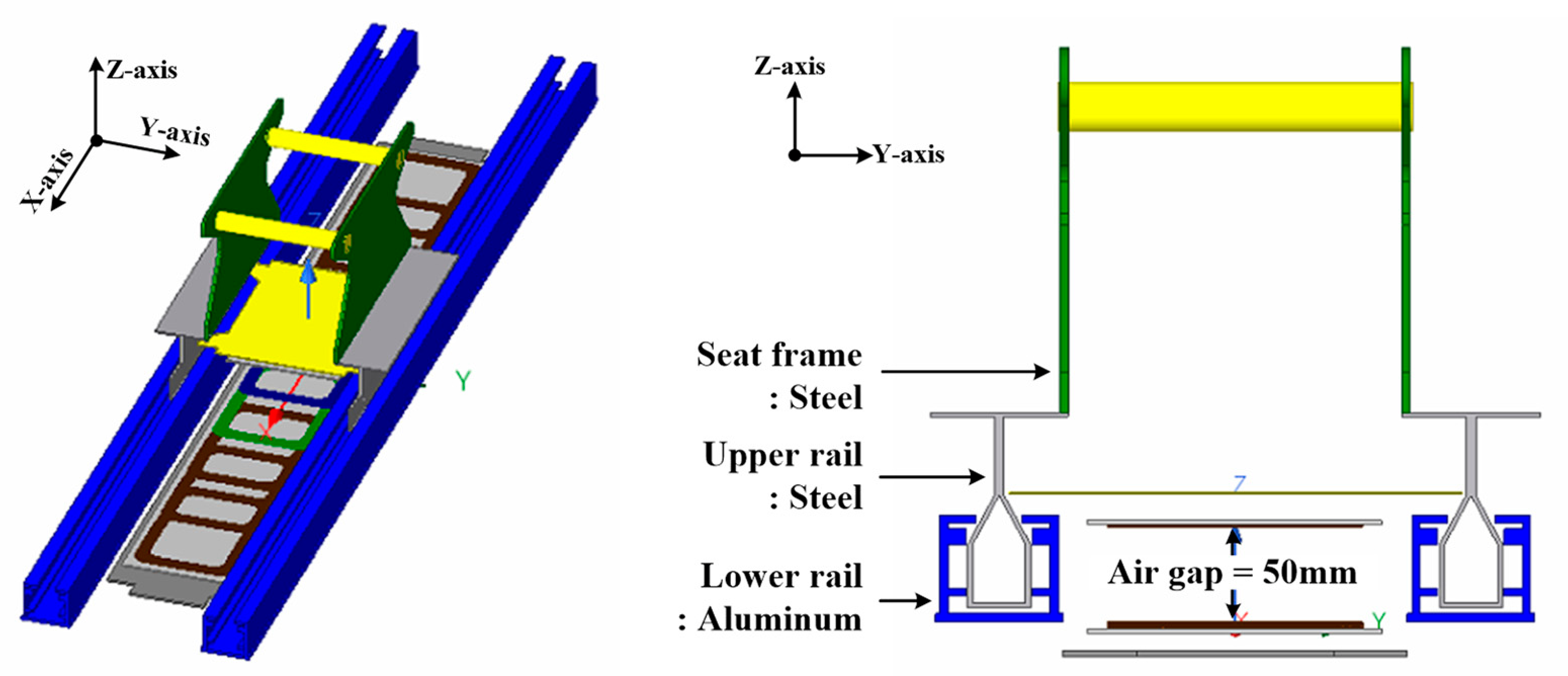
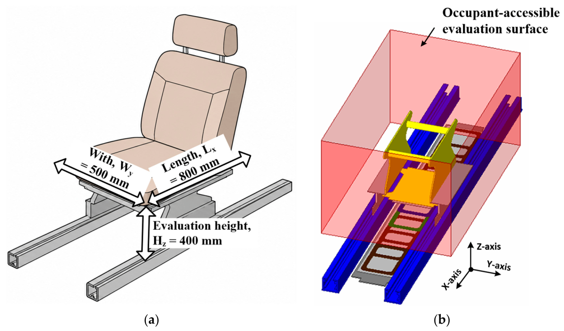
Automotive power-seat WPT systems are subject to design constraints that differ from those of conventional stationary charging systems. The receiver pad must fit within the limited space among the seat frame, actuator motors, rails, and brackets. In addition, the transmitter and receiver are positioned close to aluminum and steel structures. These structures alter the magnetic-flux distribution, inductance, ac resistance, and electromagnetic loss. Because the receiver travels along a rail that is considerably longer than the pad dimensions, a single fixed transmitter cannot readily maintain favorable coupling over the entire travel range. Furthermore, because the magnetic coupler is located directly beneath the seat, the stray magnetic field toward the occupant-side region is also an important design consideration. Consequently, the magnetic-coupler geometry, surrounding metallic structures, transmitter segmentation, position-dependent operating condition, and occupant-side field distribution should be considered within an integrated design procedure.
Various magnetic couplers, including circular pads (CPs), double-D pads (DDPs), and bipolar pads (BPPs), have been investigated to improve coupling and misalignment tolerance. A CP has a simple geometry and provides strong coupling under aligned conditions, but its coupling decreases considerably with horizontal misalignment [
7]. A DDP produces a directional bipolar magnetic field and can provide improved lateral tolerance when paired with a compatible polarized receiver [
8]. In the present application, however, the receiver is constrained to a compact, non-polarized CP because of the limited installation space beneath the seat. Accordingly, adjacent D-shaped transmitter coils are considered only as a comparison configuration for evaluating their interaction with the selected CP receiver.
A commonly reported BPP configuration employs multiple constituent coils whose current magnitudes and relative phases can be controlled to synthesize different magnetic-field distributions [
1,
9,
10]. The transmitter investigated in this study differs from such conventional BPP couplers. Rather than employing a physically separate bipolar pad, it is constructed from repeated CP segments with intentional partial overlap. The electromagnetic interaction between adjacent segments is therefore explicitly considered as part of the transmitter design.
Segmented transmitter tracks and selectively energized transmitter arrays provide another approach for supplying power over a long travel path. Segmented IPT tracks have been investigated for continuous power delivery to moving loads [
11], while selective activation of multiple transmitter coils according to receiver position has been proposed to reduce unnecessary excitation and leakage magnetic fields [
12]. The spacing between adjacent transmitters is an important design parameter because it affects both intersegment interaction and magnetic-field coverage [
1]. Overlapping transmitter arrays have also been investigated to increase magnetic-field coverage and reduce weak-field regions for moving receivers [
13]. Pahlavan et al. used overlapped resonators to improve field uniformity and reduce blank spots for a freely moving receiver [
13]. They subsequently proposed star-shaped overlapping transmitter coils to improve receiver-rotation tolerance [
14]. These studies primarily addressed planar free motion or receiver rotation rather than the one-dimensional transition of a compact CP receiver between repeated transmitter segments in a metallic automotive seat environment.
Table 1 summarizes the quantitative scope of the most directly related seat, segmented-transmitter, selective-activation, and overlapped-array studies. The comparison distinguishes their reported objectives from the rail-adjacent, metallic-seat, and predefined two-state evaluation considered here.
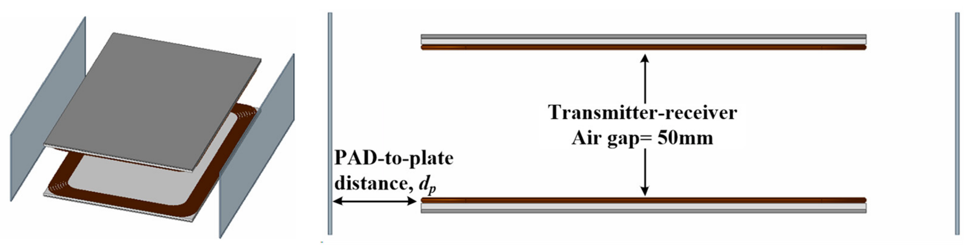
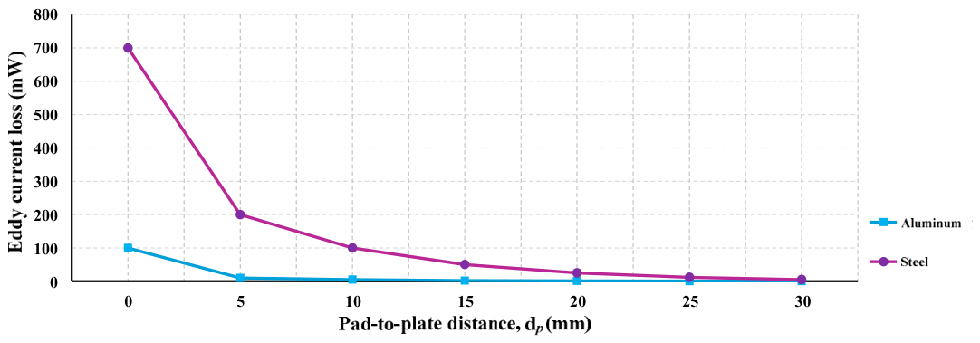
Surrounding metallic structures further complicate the design of such a segmented transmitter. Eddy currents induced in conductive vehicle structures generate additional loss and alter the leakage-field distribution. Their magnitude depends on material properties, geometry, pad-to-structure distance, operating frequency, and coil-current condition [
15]. The transmitter geometry therefore cannot be selected solely from the coupling coefficient of an isolated magnetic coupler. Moreover, receiver displacement changes the transmitter–receiver mutual inductance and consequently the coil-current condition. Winding loss, ferrite-core loss, and structural eddy-current loss can therefore exhibit different position dependencies for different excitation states. A position-dependent electromagnetic-loss assessment provides an important design basis for comparing single- and dual-segment excitation as the receiver moves along the rail.
The electrical operating condition also changes when the number of active transmitter segments is altered. Variations in mutual inductance modify the receiver-reflected impedance. Simultaneous excitation of two adjacent segments additionally introduces intersegment coupling and changes the equivalent transmitter inductance. The power-transfer capability, reflected impedance, and zero-phase-angle characteristics of IPT compensation networks have been extensively investigated [
16]. Switched-capacitor techniques have also been proposed to adapt compensation parameters when coupling or coil configurations vary [
17]. In the present work, reconfigurable compensation is therefore used as an enabling technique rather than as the primary contribution. Two predetermined transmitter-side capacitance states are employed for the evaluated single- and dual-segment excitation conditions.
Despite these advances, several issues remain insufficiently addressed for automotive power-seat WPT. First, conventional segmented-transmitter studies establish the usefulness of selective transmitter activation. However, they do not directly address the transition between intentionally partially overlapped segments under the restricted installation constraints of a power-seat rail. Second, conventional BPP and overlapping-array studies demonstrate multi-coil field shaping and improved spatial coverage. Their magnetic structures and operating objectives differ from those of repeated CP segments coupled to a compact non-polarized CP receiver. Third, a segmented transmitter installed close to aluminum and steel seat structures requires simultaneous consideration of coupling transition, branch-current distribution, position-dependent electromagnetic loss, compensation condition, and occupant-side stray magnetic field. These coupled design aspects motivate a structure- and position-aware design procedure, rather than independent consideration of the magnetic coupler and resonant circuit.
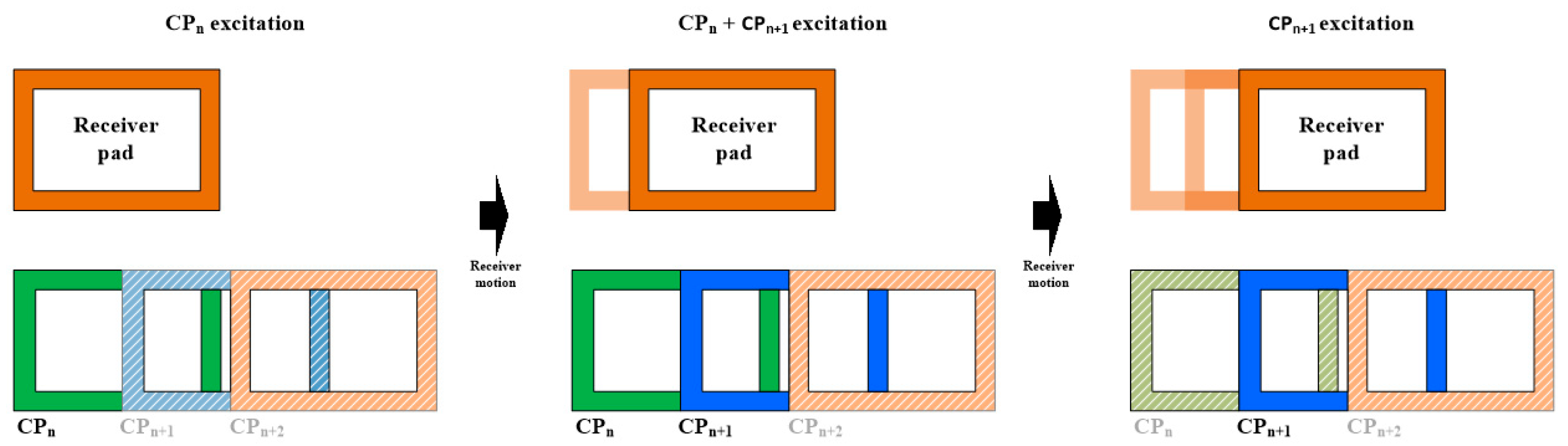
Accordingly, this study investigates a partially overlapped segmented transmitter composed of repeated CP segments. Near the center of a reference segment, only that segment is energized, which is referred to as single-segment excitation. In the transition region, the adjacent segment is simultaneously energized, which is referred to as dual-segment excitation. The dual-segment state modifies the magnetic-field distribution through the simultaneous excitation of two adjacent CP segments while remaining an operating state of the same segmented transmitter. The two adjacent transmitter segments considered in the quantitative analysis are denoted CP1 and CP2. The comparison therefore focuses on CP1-only and CP1 + CP2 excitation as the receiver moves from the CP1 center toward CP2. The position-dependent strategy is analyzed theoretically and through FEM, while representative excitation and compensation states are experimentally evaluated. The prototype evaluates predefined excitation and compensation states; real-time position-based switching and continuous-transition testing are outside the present scope.
The main contributions of this study are summarized as follows:
Candidate transmitter structures are evaluated under the constrained CP-receiver condition, and a partially overlapped architecture is established for the local intersegment transition representative of repeated rail-direction coverage; the effects of segment dimensions and partial overlap are considered in establishing the transmitter geometry;
A structure-aware three-dimensional finite element method (FEM) model incorporating the aluminum lower rail, steel upper rail, and steel seat frame is used to assess magnetic coupling, winding loss, ferrite-core loss, structural eddy-current loss, and occupant-side stray magnetic-field characteristics;
Under a common electrical reference condition, position-dependent coupling, fundamental coil currents, and electromagnetic-loss characteristics of the single- and dual-segment states are evaluated, and a three-coil equivalent-circuit model is used to characterize the branch-current distribution during dual-segment excitation; and
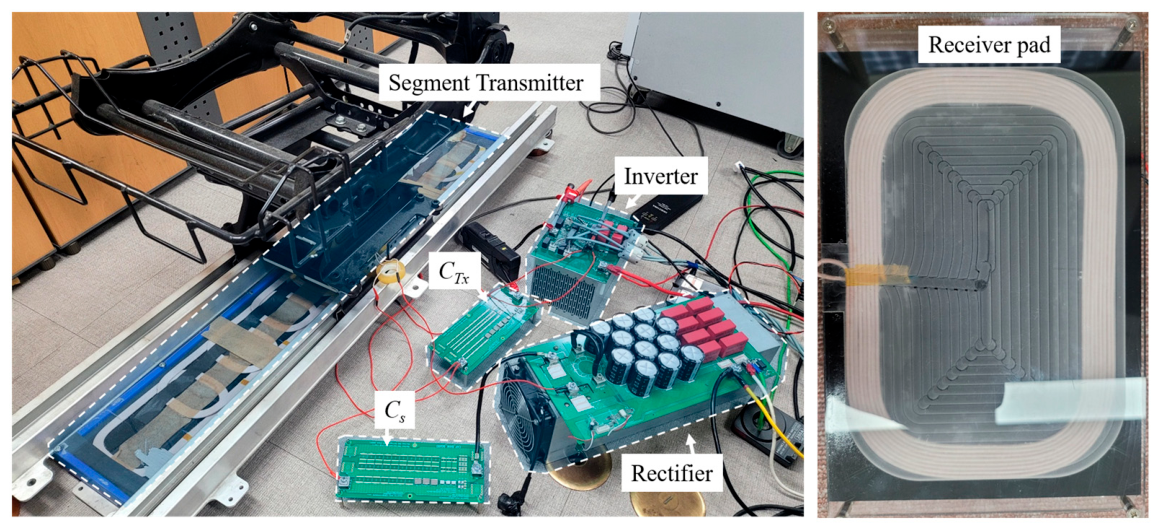
A two-state transmitter-side compensation network accommodates the different equivalent transmitter conditions, and representative operating states are experimentally evaluated using a 100 W, 110 kHz prototype.
This paper substantially extends the authors’ previous conference study [
18], which focused primarily on magnetic-parameter variations and structural eddy-current losses using simplified aluminum and steel plate models. The present study further considers the segmented-transmitter architecture, seat-structure-based geometry design, partial-overlap characteristics, position-dependent single- and dual-segment excitation, coupled branch-current behavior, reconfigurable compensation, and representative prototype validation.
3. Comparison of Candidate Transmitter Structures and Selection of the Segmented Architecture
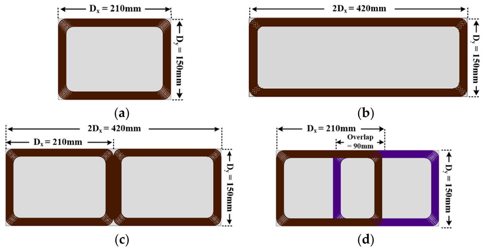
The initial topology screening was performed using a reference single-pad design area with x- and y-axis dimensions of 210 and 150 mm, respectively. Each component winding has eight turns and uses the same 1.6 mm diameter litz wire. The same receiver, transmitter-to-receiver air gap, operating frequency, and winding specification were maintained throughout the comparison. The extended-CP configurations intentionally exceed the reference x-axis dimension to investigate whether the required rail-direction coverage can be achieved by extending a single continuous transmitter winding.
Figure 2 shows the four transmitter configurations considered in the initial topology screening: a single circular pad (CP), a continuous extended CP, two adjacent D-shaped windings under same-polarity excitation, and partially overlapped CP windings.
Figure 2b presents the representative 2
Dx = 420 mm extended configuration, while both the 2
Dx = 420 mm and 3
Dx = 630 mm configurations are included in
Figure 3. For the partially overlapped configuration, an overlap length of 90 mm is used as a representative baseline. The influence of the overlap length is evaluated separately in
Section 3.6 using the selected segmented configuration with a fixed 190 mm segment length within the common maximum design envelope.
For the candidate configurations composed of two windings, the winding connection and polarity assigned in the FEM model were maintained throughout the position sweep. At this topology-screening stage, these windings are treated as components of each candidate pad configuration rather than as independently selectable CP1 and CP2 segments.
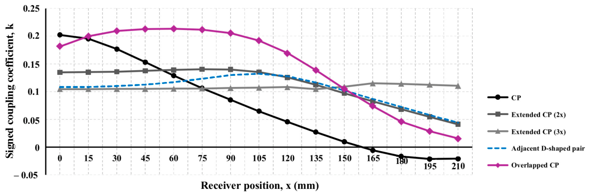
Figure 3 compares the signed coupling coefficients obtained directly from the FEM models. The sign follows the fixed winding-polarity and reference-direction conventions used for each configuration. Accordingly, a negative coupling coefficient indicates a reversal in the direction of the mutual flux linkage, rather than a negative coupling magnitude. The coupling coefficient is used only as an initial magnetic-topology screening index. A higher coupling coefficient does not necessarily correspond to higher output power or efficiency because the candidate structures have different self-inductances, conductor lengths, winding arrangements, and electromagnetic-loss characteristics. The subsequent design stages therefore consider mutual inductance, winding loss, structural eddy-current loss, circuit operating conditions, and leakage-field distribution in addition to the initial coupling trend.
3.1. Single Circular Pad
The single CP provides strong coupling near the aligned position because its magnetic flux is concentrated around the compact receiver. However, as shown in
Figure 3, the coupling coefficient decreases rapidly as the receiver moves away from the transmitter center and approaches zero at large rail-direction displacement. The coupling direction is subsequently reversed according to the fixed winding-reference convention.
This strong position dependence indicates that maintaining the required operating condition over a wide displacement range would require a substantial variation in the transmitter current or circuit operating point. Therefore, a single fixed CP does not provide a sufficiently broad coupling region for the wide seat-travel range considered in this application.
3.2. Extended Circular Pad
To examine whether the wide rail-direction displacement can be accommodated by simply extending a continuous transmitter, extended-CP configurations with x-axis lengths of 2
Dx = 420 mm and 3
Dx = 630 mm were evaluated. As shown in
Figure 3, increasing the transmitter length broadens the region over which the coupling coefficient remains relatively stable compared with that of the single CP.
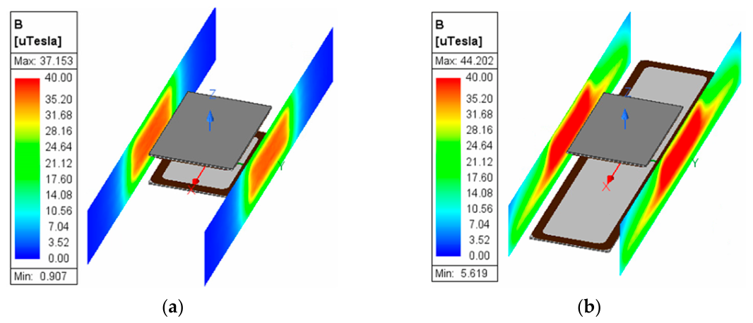
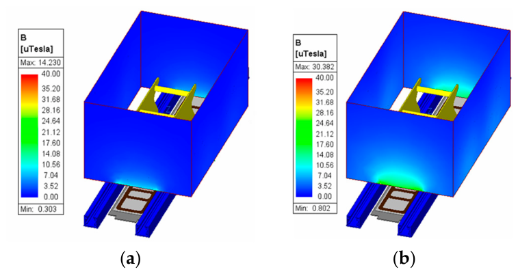
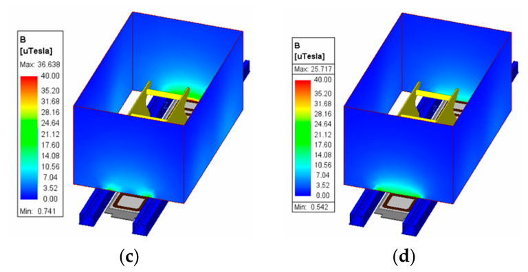
Figure 4 compares the leakage magnetic-flux-density distributions of the single and extended CPs under identical excitation conditions. A common display range of 0–40 µT is used for both configurations to emphasize the spatial extent of the high-flux-density regions. Values above the upper display limit are represented by the saturated red region. The common scale is used solely for cross-structure comparison of the leakage-field distribution.
The extended CP produces a wider high-flux-density region along the rail direction than the single CP. Increasing the winding length also increases conductor usage and winding resistance and enlarges the region in which the generated field can interact with nearby metallic seat structures. Therefore, although a continuous extended CP broadens the coupling region, extending a single transmitter winding over the rail direction is not selected as the preferred architecture for the present application.
3.3. Adjacent D-Shaped Windings Under Same-Polarity Excitation
Two adjacent D-shaped transmitter windings are included as a comparison configuration. Because the selected receiver is a compact non-polarized CP, the two D-shaped windings are assigned the same excitation polarity to investigate whether simple adjacent placement can establish a continuous coupling region with the selected receiver.
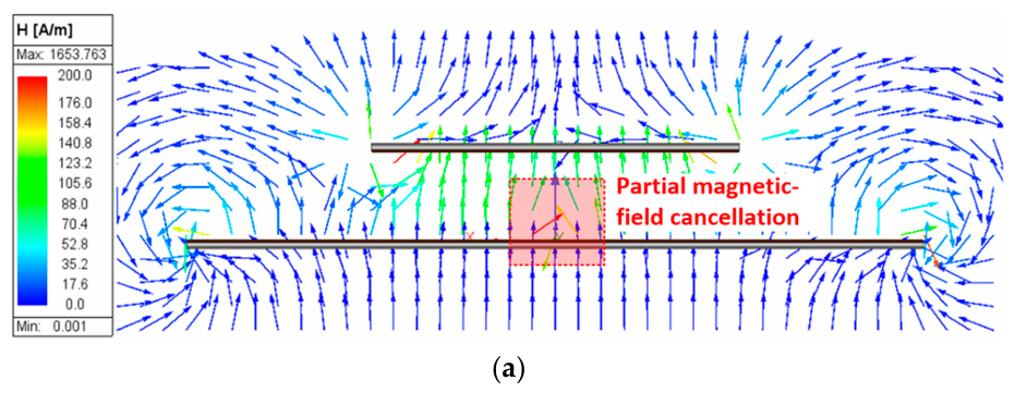
Figure 5a shows the magnetic-field-strength H vector distribution for the adjacent D-shaped winding configuration. Under the same-polarity excitation condition, the interaction between the two windings produces a local magnetic-field-cancelation region near their common boundary. This local field cancelation weakens the magnetic-field contribution toward the receiver around the inter-winding region.
The coupling-coefficient trend in
Figure 3 also shows that the adjacent D-shaped winding configuration provides a lower coupling coefficient than the partially overlapped CP-winding configuration within the representative receiver-position range used in the subsequent detailed analysis. Therefore, simple adjacent placement is not selected for the compact CP receiver considered in this study. This result is specific to the same-polarity excitation and compact non-polarized receiver condition and should not be generalized to D-shaped couplers designed for operation with a compatible polarized receiver.
3.4. Partially Overlapped CP Windings
The partially overlapped configuration is formed by arranging two CP-shaped windings with an intentional overlap along the rail direction. Unlike simple adjacent placement, the overlap changes the spatial relationship between the winding boundaries and modifies the magnetic-field superposition in the intermediate region.
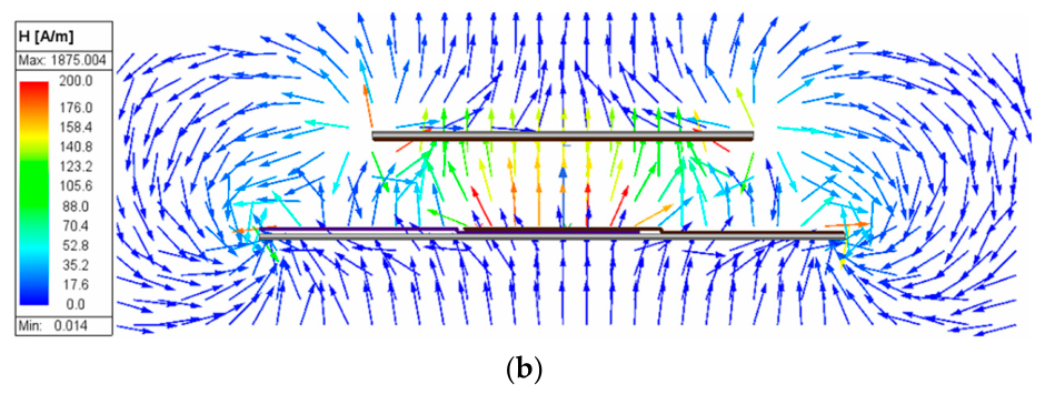
Figure 5b shows the magnetic-field-strength H vector distribution of the partially overlapped CP-winding configuration. Compared with the adjacent D-shaped winding configuration shown in
Figure 5a, the partially overlapped geometry produces a more continuous magnetic-field distribution toward the compact CP receiver across the intermediate region. The corresponding coupling-coefficient trend in
Figure 3 maintains a comparatively high coupling level near the reference winding and throughout the inter-winding transition region.
At this topology-screening stage, the partially overlapped winding arrangement is evaluated within the same maximum design envelope used for the other candidate configurations. The influence of the overlap length is examined separately in
Section 3.6 before the selected geometry is applied to the seat-structure-based analysis in
Section 4.
3.5. Selection of the Segmented Transmitter Architecture
The single CP provides strong coupling near alignment but exhibits rapid coupling degradation with rail-direction displacement. Extending a continuous CP broadens the coupling region but increases the winding length and the spatial extent of the high-flux-density region. The adjacent D-shaped windings under same-polarity excitation exhibit local magnetic-field cancelation near their common boundary under the selected compact CP-receiver condition.
In comparison, the partially overlapped CP-winding configuration produces a more continuous magnetic-field distribution across the intermediate region and maintains a relatively high coupling coefficient over the receiver-position range considered in the subsequent detailed analysis. In addition, its repeated winding geometry can be implemented as independently selectable transmitter segments without requiring one continuous winding to extend over the entire rail length.
Based on this topology-level comparison, the partially overlapped segmented transmitter is selected for the subsequent design stages. This selection establishes the transmitter architecture but does not yet determine the overlap length or the final segment dimensions. The influence of the overlap length is evaluated in
Section 3.6 using the selected 190 mm segment geometry within the common maximum design envelope, after which the selected overlap is applied to the structure-aware segment-dimension study in
Section 4.
3.6. Influence of Overlap Length on Segment Coupling Characteristics
The 210 mm x-axis dimension used in
Section 3.1,
Section 3.2,
Section 3.3,
Section 3.4 and
Section 3.5 represents the common maximum design envelope for topology-level screening. Following selection of the partially overlapped architecture, the x-axis outer length of each transmitter segment is set to
Dx = 190 mm. Relative to the common envelope, this retains a total of 20 mm geometric clearance for the winding bends and separation from the ferrite-sheet boundary.
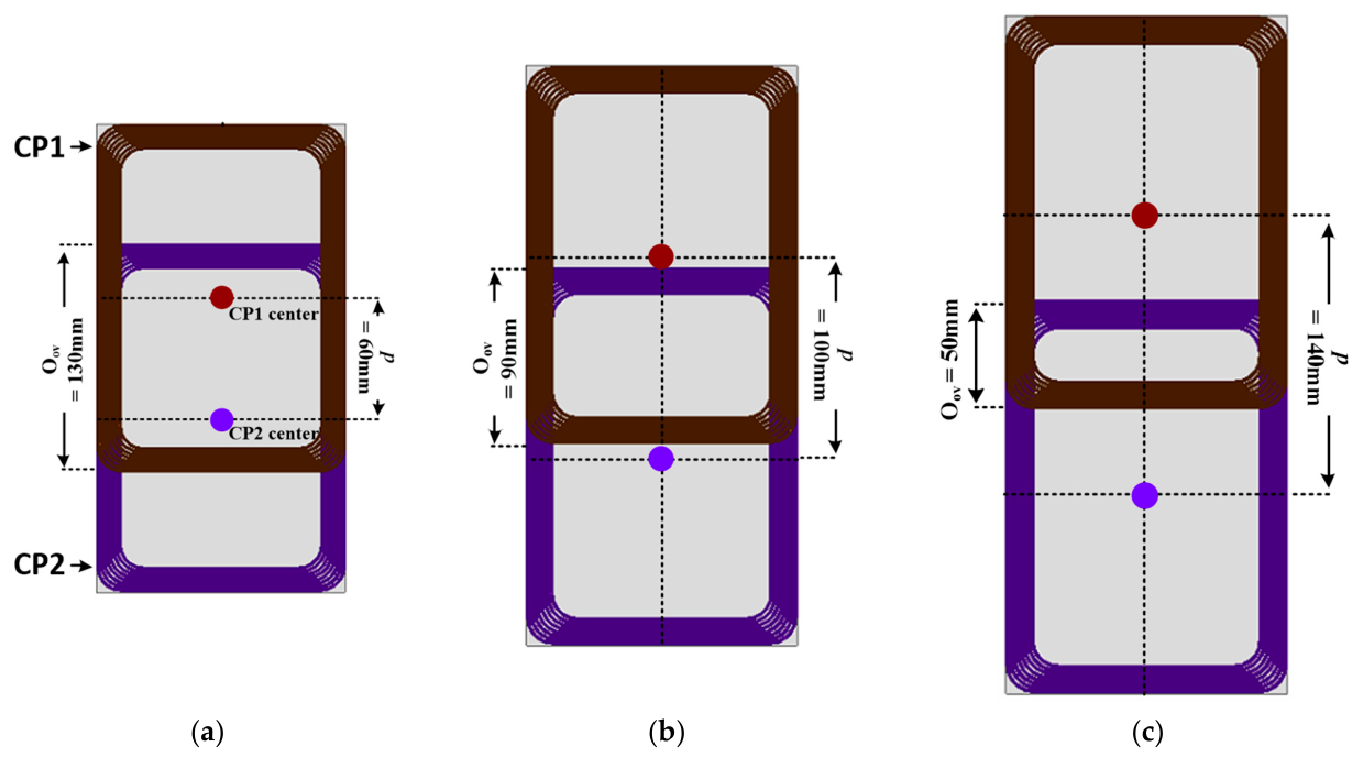
Figure 6 defines the overlap length
Oov and center-to-center pitch p =
Dx −
Oov. Overlap lengths of 50, 70, 90, 110, and 130 mm are evaluated, corresponding to pitches of 140, 120, 100, 80, and 60 mm, respectively. The receiver geometry, air gap, operating frequency, and winding specifications are maintained throughout the comparison.
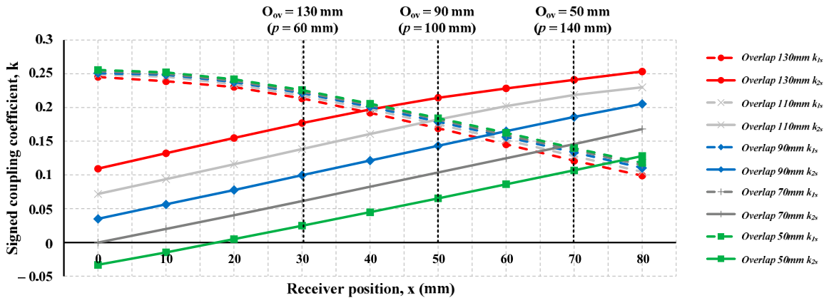
Figure 7 shows the signed coupling coefficients
k1s and
k2s between the receiver and CP1 and CP2, respectively. As the receiver moves from the CP1 center along the positive x-direction,
k1s decreases while
k2s increases. A larger overlap reduces the segment pitch and causes the CP2 coupling contribution to become significant at an earlier receiver position. At
x = 0 mm,
k1s changes only slightly among the evaluated overlap lengths because the receiver remains aligned with the CP1 center. In contrast,
k2s changes from negative to positive coupling and increases substantially as the overlap length increases. The extent of this overlap-dependent variation is comparable to the position-dependent variation in
k1s over the evaluated receiver-position range, demonstrating that the overlap length materially affects the coupling transition between adjacent segments.
The vertical lines in
Figure 7 indicate the geometric midpoint (
x = p/2) for the representative configurations shown in
Figure 6. The common
x = 0–80 mm range is used to compare all overlap configurations over the same physical receiver displacement from the CP1 center. The vertical markers at
x = p/2 identify the geometry-dependent midpoint between adjacent segment centers; data beyond each marker are retained for the common-position comparison and are not interpreted as a normalized transition interval. These locations do not necessarily correspond to identical
k1s and
k2s values or predetermined excitation-switching boundaries. Increasing the overlap from 50 to 130 mm also reduces the pitch from 140 to 60 mm, increasing the nominal segment density required per unit rail length by a factor of (140/60 = 2.33). Thus, a larger overlap promotes an earlier contribution from the adjacent segment but reduces the rail length covered by each repeated segment interval and increases the potential implementation complexity.
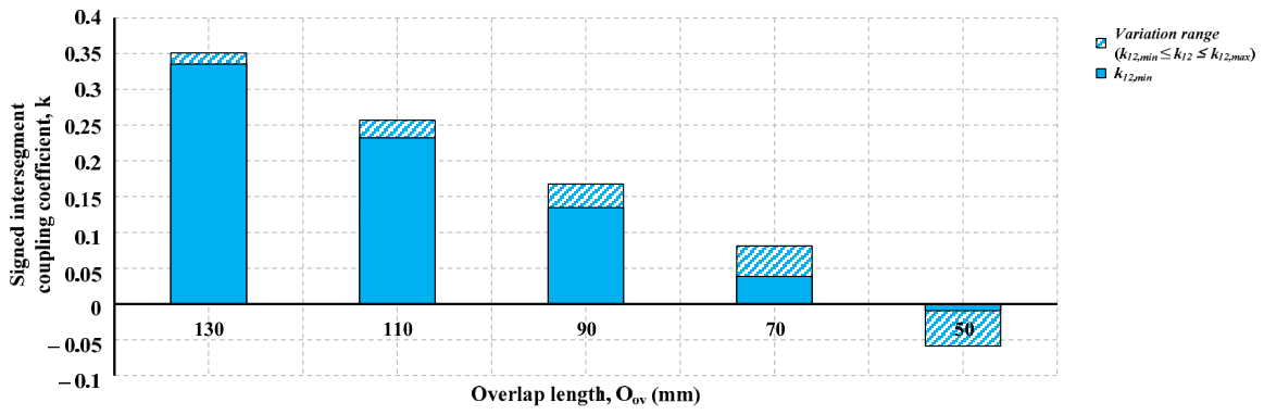
Figure 8 compares the minimum and maximum signed intersegment coupling coefficients k
12 obtained over the evaluated receiver-position range for each overlap length. Although k
12 varies with receiver position, the variation within each overlap configuration is smaller than the change produced by varying the overlap length. The 50 mm overlap maintains negative k
12 values over the evaluated positions, whereas the 70 mm overlap produces a small positive coupling range. Increasing the overlap to 90, 110, and 130 mm results in progressively stronger positive intersegment coupling. These results confirm that the overlap length is a dominant geometric factor governing the direct magnetic interaction between adjacent transmitter segments. Nevertheless, the sign and magnitude of k
12 alone do not determine branch-current division or circuit performance, which are examined later using the three-coil equivalent-circuit model.
The 90 mm overlap provides an intermediate 100 mm pitch, for which
x = 50 mm corresponds to the geometric midpoint between the segment centers. Around this representative intermediate position, both k
1s and k
2s remain positive and appreciable, while k
12 remains at a moderate positive level relative to the larger-overlap configurations. The 90 mm overlap also avoids the high segment density and strong intersegment interaction associated with the 110 and 130 mm overlaps, as well as the near-decoupled or reversed mutual-flux-linkage conditions associated with the smaller overlaps. These geometry-level trends identify the 90 mm overlap as a balanced design point for the coupling transition, intersegment interaction, segment pitch, and nominal segment density. This geometry is used in the structure-aware segment-dimension and electromagnetic-loss analyses of
Section 4.
6. Equivalent-Circuit Analysis and Reconfigurable Compensation
6.1. Single-Segment Excitation
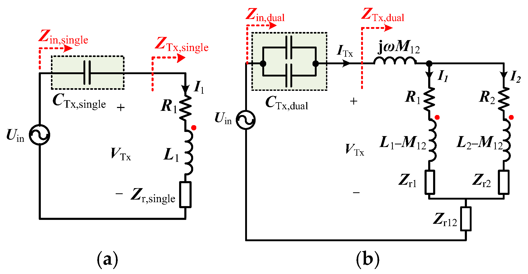
Figure 21a shows the FHA equivalent circuit under single-segment excitation. In the single-segment state, the segment-selection circuit disconnects CP2 from both the inverter and the transmitter-side compensation network. CP2 therefore forms an open loop, so no branch current flows and no receiver-reflected impedance appears through CP2 in
Figure 21a. The geometric coupling
M12 and the corresponding open-circuit induced voltage remain, whereas switch off-state parasitics are outside the scope of this idealized model. One transmitter segment and the receiver form a two-coil series–series compensated circuit. In
Figure 21,
Uin denotes the rms fundamental inverter-output voltage applied to the compensation network, whereas
VTx denotes the rms fundamental voltage across the coupled transmitter-coil network after the common transmitter-side series compensation capacitor. The inverter dc-link voltage used in the experiment is denoted separately by
VDC. In the phasor-domain FHA model,
j represents a 90° phase shift, and
ω denotes the angular operating frequency.
The active transmitter-coil impedance and the compensated receiver-side impedance are defined as
Here,
R1 and
Rs are the equivalent ac resistances of the active transmitter segment and receiver coil, respectively;
L1 and
Ls are their self-inductances;
Cs is the receiver-side series compensation capacitance; and
RL is the FHA-equivalent ac load resistance referred to the receiver-coil terminals. The receiver-reflected impedance and the equivalent impedance of the coupled transmitter network under single-segment excitation are
Including the common transmitter-side series compensation capacitor, the inverter-side input impedance is
The implemented value of
CTx,single is introduced with the reconfigurable compensation network in
Section 6.4. As the receiver moves away from the CP1 center,
M1s and the corresponding reflected impedance vary, thereby changing both the magnitude and phase of
Zin,single.
6.2. Simultaneous Dual-Segment Excitation and Reflected-Impedance Decomposition
Figure 21b shows the simultaneous dual-segment excitation circuit. CP1 and CP2 form parallel transmitter branches after the common transmitter-side series compensation capacitor and therefore share the same network voltage
VTx. Together with the receiver, the two transmitter segments form a three-coil system. Based on the current directions and dot convention shown in
Figure 21b, the KVL equations are
Here, Z2 = R2 + jωL2, and I1, I2, and Is are the complex rms current phasors of CP1, CP2, and the receiver, respectively. M12 is the direct mutual inductance between CP1 and CP2, whereas M1s and M2s are the mutual inductances between each transmitter segment and the receiver. The negative transmitter–receiver coupling terms follow the selected current references and dot convention. The 3 × 3 impedance matrix remains symmetric, consistent with electromagnetic reciprocity, and the receiver-loop equation represents the condition that the induced electromotive forces and receiver-side impedance voltage sum to zero.
Defining the total transmitter current as
ITx =
I1 +
I2, the KVL equations can be reorganized into one reflected-impedance term common to the transmitter port and two branch-differential reflected-impedance terms. These components are defined as
The term Zr12 is the receiver-mediated reflected impedance common to both transmitter branches. In contrast, Zr1 and Zr2 are differential reflected impedances arising from the difference between M1s and M2s. These terms are an algebraic decomposition of the coupled three-coil impedance rather than three independent physical loads. When M1s = M2s, Zr1 and Zr2 become zero, and the receiver-reflected contribution is represented only by the common term Zr12. In this notation, the subscript r denotes a reflected-impedance component, whereas s denotes the secondary receiver side.
The equivalent impedance of the coupled transmitter-coil network excluding the common series compensation capacitor is therefore
Equation (7) separates the common port component, j
ωM12 +
Zr12, from the parallel combination of the two differential branch impedances. Including the common transmitter-side series compensation capacitor, the inverter-side input impedance under simultaneous dual-segment excitation is
The implemented value of
CTx,dual is presented in
Section 6.4. Equations (6)–(8) provide a circuit-level interpretation of the simultaneous dual-segment input impedance without requiring the intermediate KVL solution to be expanded in the main text.
6.3. Branch-Current Distribution Under Simultaneous Dual-Segment Excitation
The common port component j
ωM12 +
Zr12 affects the total simultaneous dual-segment input impedance but is identical for the two transmitter branches and therefore does not directly determine their current division. Removing this common voltage component from the two branch equations gives the branch-current ratio
Because CP1 and CP2 have the same geometry, number of turns, conductor specification, and nominal compensation condition, their coil impedances can be approximated as
Z1 ≈
Z2 ≡
Z0. Defining the mutual-inductance difference as Δ
M =
M1s −
M2s, Equation (9) can be written as
Equation (10) shows that the branch-current ratio is not governed by ΔM alone. The difference between M1s and M2s enters through the differential reflected terms ω2M1sΔM/Zs and −ω2M2sΔM/Zs. Their influence is determined relative to the common branch term Z0 − jωM12, which appears in both the numerator and denominator. Therefore, even when M1s and M2s differ, the current ratio remains close to unity when the differential reflected terms are small compared with the common branch term.
The branch-current imbalance ratio is defined as
At x = 50 mm, the calculated rms branch-current magnitudes are 2.28 A for CP1 and 2.37 A for CP2, corresponding to an imbalance ratio of 3.87%. Thus, under the investigated transition-region condition, the unequal transmitter-to-receiver mutual inductances produce only a limited branch-current imbalance. This result applies only to the analyzed geometry and compensation condition and does not imply balanced branch currents at all receiver positions or under all parameter tolerances.
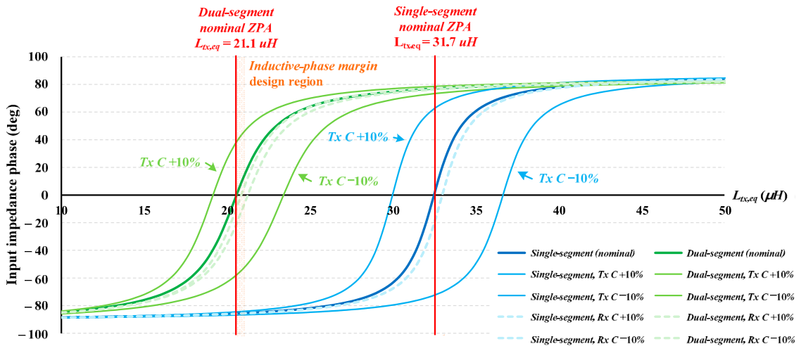
6.4. Reconfigurable Compensation and Inductive Input-Impedance Region
Single- and dual-segment excitation produce different equivalent transmitter impedances because the active-segment count and contribution of M12 differ. A single fixed transmitter-side compensation capacitance cannot therefore maintain the intended input-impedance phase under both excitation states.
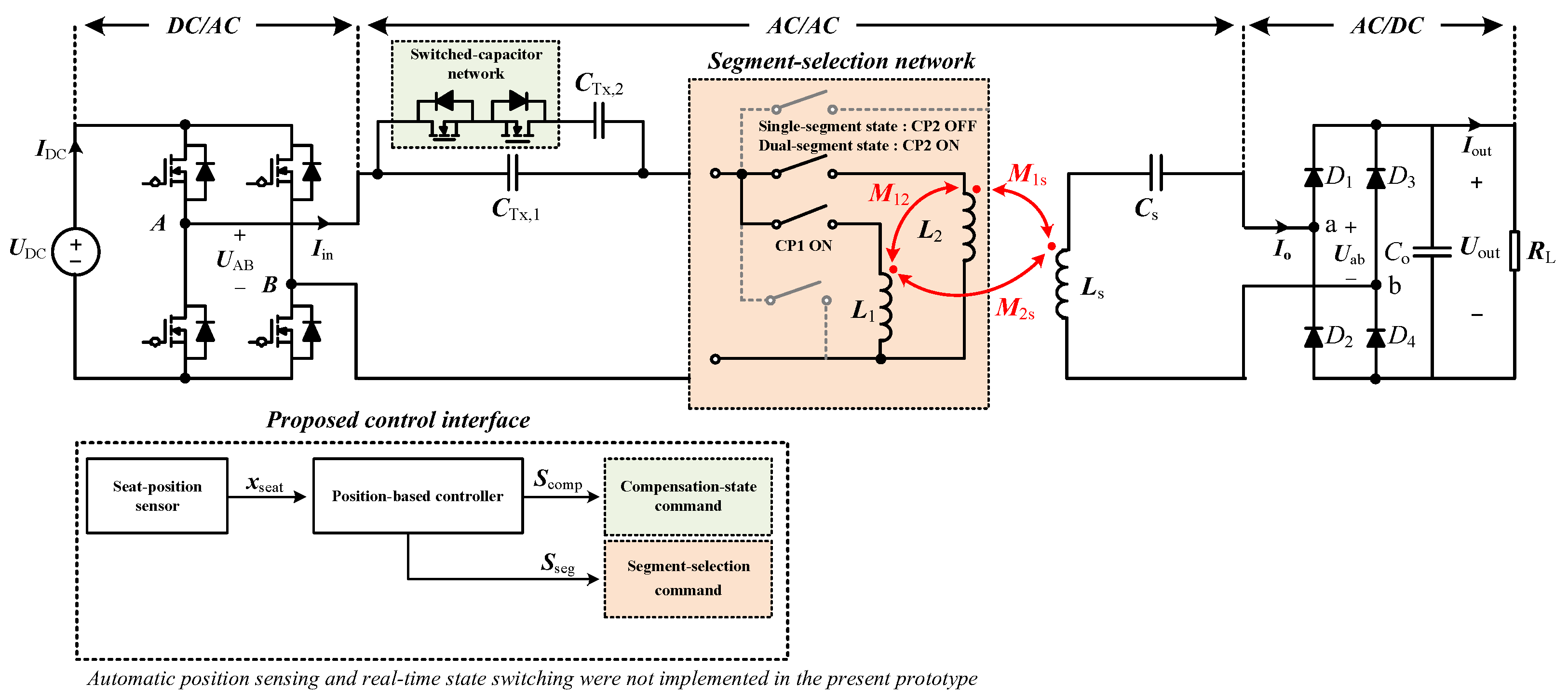
The two-state network in
Figure 22 uses a 66 nF base transmitter capacitor under single-segment excitation. Under simultaneous dual-segment excitation, an additional 33 nF capacitor is connected in parallel, increasing the effective transmitter-side capacitance to 99 nF. The receiver-side series compensation capacitance
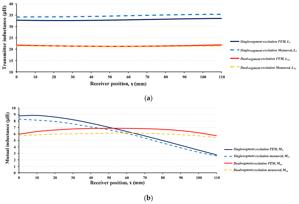
Cs is fixed at 56 nF. The representative equivalent transmitter inductances used in the compensation analysis are 33.2 μH under single-segment excitation and 21.3 μH under simultaneous dual-segment excitation.
To assess the first-order sensitivity of the compensation network, the effective transmitter-side capacitance CTx and receiver-side capacitance Cs were independently varied by ±10%, while the remaining circuit parameters were fixed at their nominal values. For the dual-segment state, the ±10% variation was applied to the effective total transmitter capacitance of 99 nF, representing the same-direction worst-case deviation of the 66 and 33 nF capacitor banks.
Figure 23 shows nominal ZPA points of 31.7 and 21.1 μH for the single- and simultaneous dual-segment compensation states, respectively. Variation in
CTx produces a larger shift in the ZPA point than the corresponding variation in
Cs. At representative equivalent transmitter inductances of 33.2 and 21.3 μH, the nominal input-impedance phases are 9.32° and 7.22°, respectively. These positive phase angles indicate nominal inductive operation but do not guarantee ZVS. Under adverse capacitor-tolerance combinations, the ZPA point may shift beyond the representative operating inductance and cause capacitive operation. Tight-tolerance capacitors or post-assembly compensation adjustment may therefore be required.
8. Discussion
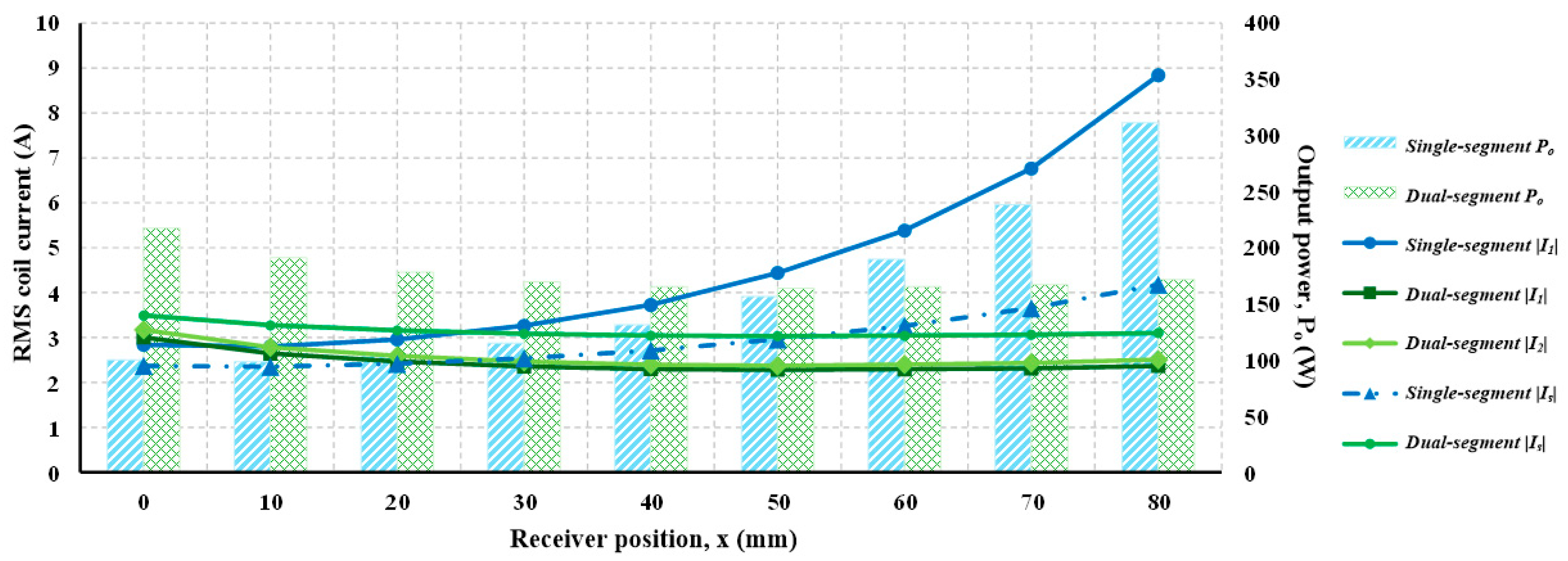
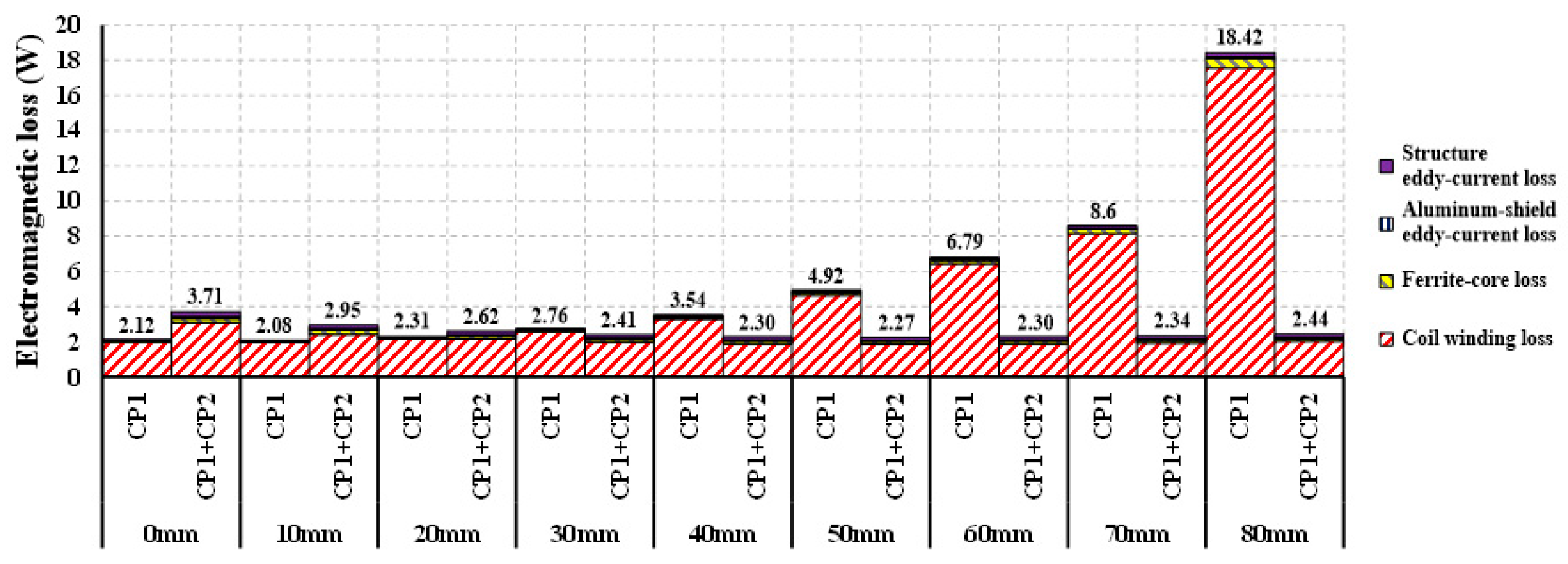
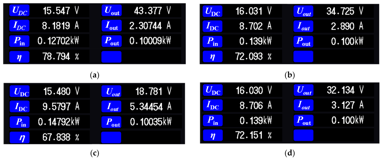
The results show that excitation-state selection should not be based on coupling coefficient alone. At x = 0 mm, near the CP1 center, CP1 excitation provides sufficient coupling and lower total electromagnetic loss. As the receiver moves away from CP1, maintaining CP1 excitation requires a rapid increase in |I1|. This raises the CP1 winding loss and may produce an output voltage below the specified range, even when an approximately 100 W operating point is established by adjusting the electronic dc load.
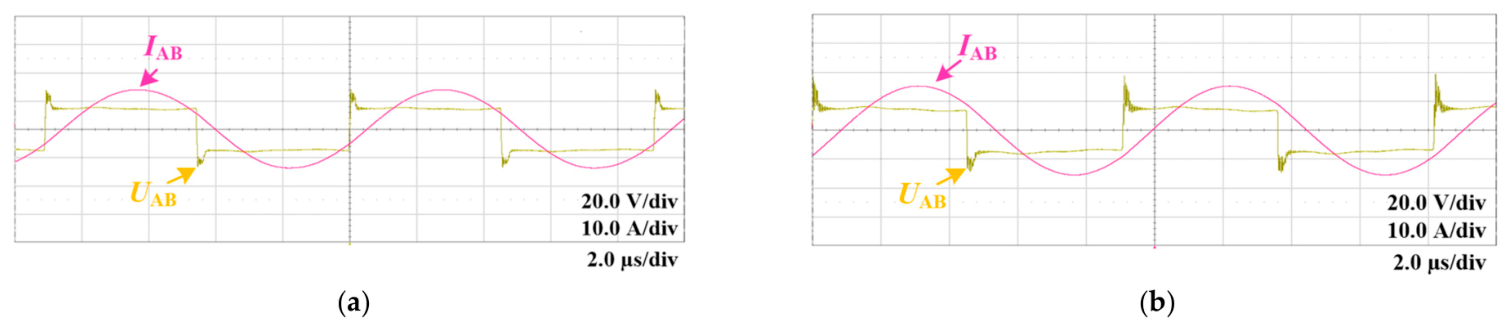
At x = 50 mm, CP1 + CP2 excitation reduces the absolute modeled electromagnetic loss by 53.9% relative to CP1 excitation at their respective calculated operating points under the common fixed-source and fixed-load condition. This percentage is not an equal-output efficiency improvement. At x = 80 mm, the separately adjusted approximately 100 W prototype test shows that CP1 + CP2 excitation establishes an output voltage above the 30 V minimum and improves the measured dc-to-dc efficiency relative to continued CP1 excitation.
The first-order geometric screening index
Msum is useful for selecting the transmitter-segment width but does not represent the complete performance under simultaneous dual-segment excitation because it excludes
M12, the transmitter branch impedances, and the complex current distribution. The three-coil analysis decomposes the receiver-reflected impedance into the common term
Zr12 and the branch-differential terms
Zr1 and
Zr2. The common port component jω
M12 +
Zr12 affects the total input impedance but does not directly determine current division. Instead, the branch-current ratio is governed by the two differential branch impedances. Under the investigated transition-region condition, these differential reflected terms remain small relative to the common branch term, resulting in a calculated current imbalance of 3.87% at
x = 50 mm. Similarly, the losses calculated under the common 1 A rms condition in
Section 4 are comparative design indicators, whereas the position-dependent total electromagnetic losses in
Section 5 use the calculated operating-current phasors.
The calculated total electromagnetic loss includes the transmitter and receiver winding losses, ferrite-core loss, aluminum-shield eddy-current loss, and eddy-current losses in the surrounding seat structures. The measured dc-to-dc loss additionally includes the inverter, compensation capacitors, segment-selection devices, wiring, rectifier, and output stage. The FEM results should therefore be interpreted as magnetic-coupler design indicators rather than direct predictions of total system efficiency.
The two-state reconfigurable transmitter-side compensation network uses discrete single- and dual-segment compensation states rather than continuous online tuning. The input-impedance phase analysis establishes inductive operating regions, but actual ZVS also depends on current magnitude, switch output charge, dc-link voltage, and dead time. The measured switching waveforms verify ZVS only for the tested operating points. The first-order capacitor-tolerance analysis does not constitute a complete position–load input-phase map and does not include the on-resistance of the segment-selection switches or layout parasitics.
The present FEM study is limited to rail-direction receiver displacement under nominal geometry and material properties. Manufacturing tolerances, transverse or rotational misalignment, and temperature-dependent material and winding parameters were not evaluated. Long-term coil aging and the resulting drift in winding resistance and inductance were not separately evaluated and should be included in future robustness testing. Experimental validation was limited to static endpoint operation; the full load range and quantitative ZVS-current limits also remain to be established. Future work will address sensitivity to position uncertainty, hysteresis-band design, and dynamic state transitions. Circuit-level overlap optimization, detailed converter-loss separation, system-level thermal behavior, and battery-load validation also remain for future study.
9. Conclusions
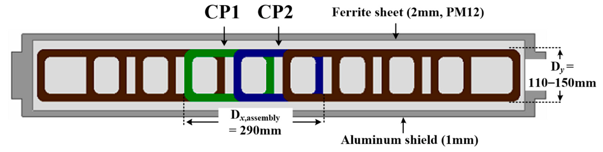
This paper proposed a structure-aware, partially overlapped segmented transmitter with a position-dependent single- and simultaneous dual-segment excitation strategy for automotive power-seat WPT. Candidate magnetic couplers were compared under a compact CP-receiver condition, and a seat-structure FEM model incorporating the aluminum lower rail, steel upper rail, and steel seat frame was used to select 190 × 130 mm transmitter segments. The final overlap length, center-to-center pitch, and overall two-segment transmitter-assembly length are 90, 100, and 290 mm, respectively.
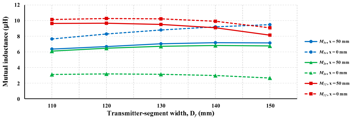
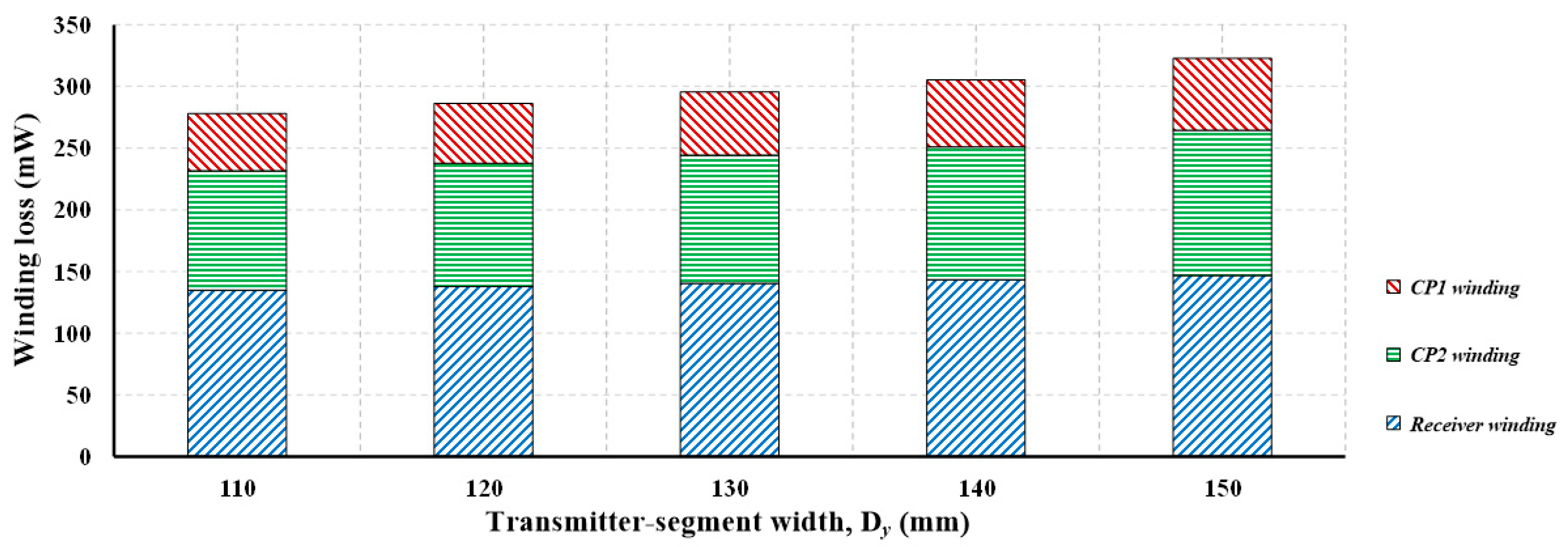
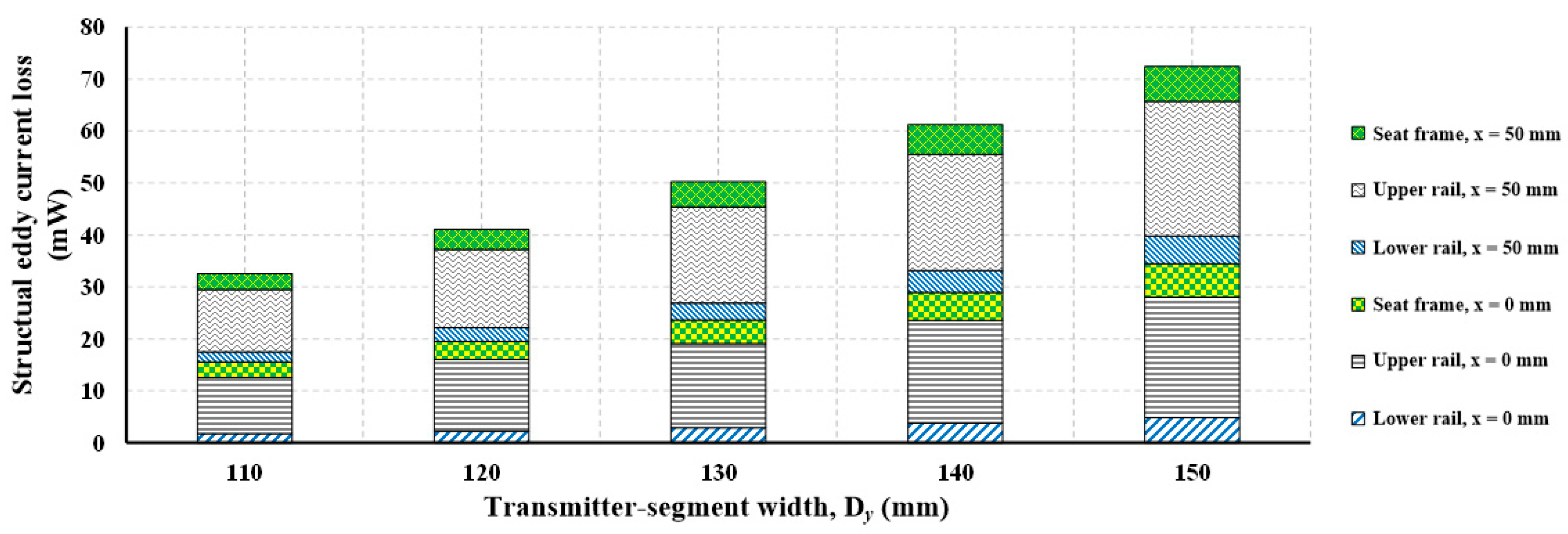
The common 1 A rms FEM simulations showed that increasing Dy beyond 130 mm provides limited mutual-inductance benefit while increasing total winding loss and structural eddy-current loss. Under the common fixed-source and fixed-load condition, CP1 excitation produced lower total electromagnetic loss at x = 0 mm, whereas CP1 + CP2 excitation produced lower loss at x = 50 and 80 mm. The three-coil equivalent-circuit analysis decomposed the dual-segment receiver-reflected impedance into Zr12, Zr1, and Zr2 and showed that current division is governed by the differential branch impedances rather than by M1s and M2s alone. At x = 50 mm, the calculated branch-current imbalance was 3.87%.
The two-state compensation network provides effective transmitter capacitances of 66 nF under single-segment excitation and 99 nF under simultaneous dual-segment excitation, while the receiver-side capacitance remains 56 nF. At x = 0 mm, CP1 excitation achieved a dc-to-dc efficiency of 78.79%, 6.70 percentage points higher than CP1 + CP2 excitation. At x = 80 mm, CP1 + CP2 excitation established the approximately 100 W operating point at a dc output voltage of 32.13 V and a dc-to-dc efficiency of 72.15%, compared with 18.78 V and 67.84% under CP1 excitation. ZVS was verified using the measured drain–source voltage, gate–source voltage, and inverter-current waveforms.
The results support the offline design rationale for changing from CP1 to CP1 + CP2 excitation as the receiver moves away from the CP1 center. Future work will implement position sensing with hysteretic state selection and validate dynamic transitions during continuous seat movement, followed by thermal and battery-load evaluations.