1. Introduction
The global transition toward electrified transportation has accelerated significantly during the past decade, driven by decarbonization initiatives, advances in energy-storage technologies, and increasing governmental support for sustainable mobility [
1,
2]. Electric vehicles (EVs) have evolved from niche transportation products into a major component of modern transportation infrastructure, with global EV sales continuing to grow despite fluctuations in regional economic conditions [
3,
4]. Global electric vehicle landscape based on data reported in the IEA Global EV Outlook 2026, presents the continued acceleration of transportation electrification worldwide [
5]. This rapid expansion has intensified demand for rechargeable battery systems, placing lithium-ion batteries (LIBs) at the center of contemporary energy-storage research due to their high energy density, long cycle life, and favorable power characteristics [
6,
7].
As battery packs increase in capacity and complexity, battery management systems (BMSs) have become essential for ensuring operational safety, reliability, and performance [
8,
9]. A typical EV battery pack consists of numerous individual cells connected in series and parallel configurations to achieve the required voltage and energy capacity [
10]. Manufacturing tolerances, aging mechanisms, temperature gradients, and operating conditions inevitably introduce variations among cells, resulting in state-of-charge (SoC), capacity, and internal resistance imbalances [
11]. If left unmanaged, these imbalances can reduce usable pack capacity, accelerate degradation, increase thermal stress, and shorten battery service life [
12,
13,
14].
Cell-balancing is therefore recognized as one of the most critical functions of a modern BMS [
15]. Existing balancing approaches are commonly classified as passive or active methods [
10]. Passive balancing dissipates excess energy through resistive elements and offers simplicity and low cost but suffers from energy losses and thermal inefficiencies [
16]. Active balancing techniques improve energy utilization by transferring charge among cells through capacitive, inductive, transformer-based, or converter-assisted topologies [
17,
18,
19,
20]. Although active methods can achieve superior balancing performance, they often introduce additional hardware complexity, increased component count, higher cost, and more challenging control requirements [
21,
22]. These trade-offs become increasingly significant when balancing large battery packs intended for commercial transportation applications.
To address these limitations, numerous researchers have investigated reconfigurable battery architectures capable of dynamically altering electrical interconnections among cells [
23,
24]. Such approaches aim to improve balancing effectiveness while reducing reliance on dedicated energy-transfer circuits. Among these emerging strategies, an adaptive cell recombination approach was previously proposed by the authors, in which battery cells are dynamically reconfigured through a relay-based architecture to promote natural charge redistribution under charging, discharging, and resting conditions [
25]. The original study demonstrated the theoretical feasibility of the concept through simulation-based investigations and reported promising balancing performance across multiple operating scenarios.
Despite the encouraging simulation results reported in the previous work, a significant research gap remains between theoretical validation and practical implementation. Simulation environments typically assume ideal switching behavior, negligible wiring losses, perfect measurements, and uniform cell characteristics. In contrast, real battery systems are affected by relay switching delays, sensor uncertainty, contact resistance, voltage relaxation effects, cell aging, and numerous non-ideal phenomena that can substantially influence balancing performance. Consequently, simulation results alone are insufficient to establish the practical feasibility of a balancing strategy intended for real-world deployment.
A review of the available literature reveals that experimental validation studies focusing on adaptive reconfigurable balancing architectures remain comparatively limited. While many publications present simulation-based analyses, relatively few demonstrate complete hardware implementation and experimental verification under realistic operating conditions. This lack of practical validation restricts the ability to assess scalability, implementation challenges, control behavior, and real-world balancing effectiveness.
The present study addresses this gap by experimentally validating the previously published adaptive cell recombination balancing model using a custom-developed hardware prototype. The prototype was constructed using commercially available components and second-life Panasonic NCR18650PF lithium-ion cells representative of cells commonly deployed in e-mobility applications. Experimental investigations were conducted under resting, charging, and discharging conditions using multiple balancing scenarios to evaluate the effectiveness of the proposed architecture. The experimentally observed balancing behavior is subsequently compared with previously published simulation results to assess the degree of agreement between theoretical predictions and physical implementation.
The primary contribution of this work is the successful transition of the adaptive cell recombination balancing concept from simulation to hardware realization. Beyond validating the balancing strategy itself, the study provides practical insights into prototype development, switching implementation, measurement considerations, operational limitations, and the use of second-life lithium-ion cells for sustainable battery research. The findings contribute to the growing body of knowledge on reconfigurable battery management architectures and provide a foundation for future investigations involving larger battery systems, advanced control strategies, and real-world EV applications.
2. Background and Motivation
The development of modern electric vehicles has been closely linked to advances in battery technology [
26,
27]. Early electrified transportation systems relied primarily on lead–acid and nickel-based batteries [
28], which were limited by low energy density and relatively short cycle life [
29,
30,
31,
32]. The commercialization of lithium-ion batteries transformed the EV industry by enabling substantially higher energy density, improved power capability, longer service life, and reduced weight, thereby supporting the large-scale deployment of modern electric vehicles [
33,
34,
35,
36].
Among contemporary battery technologies, lithium-ion batteries remain the dominant energy-storage solution for EV applications due to their favorable balance of energy density, efficiency, cycle life, and technological maturity [
7,
37]. Various lithium-ion chemistries, including lithium nickel manganese cobalt oxide (NMC), lithium nickel cobalt aluminum oxide (NCA), lithium iron phosphate (LFP), and lithium manganese oxide (LMO), are currently employed across different vehicle segments depending on performance, cost, and safety requirements [
38,
39,
40,
41,
42]. Commercial EV batteries are commonly manufactured in cylindrical, prismatic, and pouch-cell formats, each offering distinct advantages in packaging flexibility, thermal management, and manufacturing scalability [
40,
43]. The Panasonic NCR18650PF cells utilized in this study represent a widely adopted cylindrical lithium-ion format that has been extensively deployed in practical e-mobility applications.
Recent battery pack development trends have increasingly emphasized Cell-to-Pack (CTP) and Cell-to-Chassis (CTC) integration strategies, which reduce structural overhead and improve volumetric energy density by minimizing intermediate module components [
44,
45,
46,
47]. Simultaneously, the continuous increase in battery pack capacity and cell count has significantly elevated the complexity of battery management functions [
48,
49]. Modern EV battery systems therefore rely on sophisticated BMS to monitor cell voltages, currents, temperatures, and state variables while ensuring safe and efficient operation [
50,
51]. The evolution of battery technologies, cell formats, and pack architectures has progressively increased the importance of advanced battery management functions, particularly cell-balancing strategies, which are essential for maximizing energy utilization, maintaining safety, and extending battery service life [
20,
37,
52].
Tesla and Rivian predominantly employ cylindrical cell designs to achieve high energy density, scalability, and effective thermal management [
53,
54], whereas BYD utilizes its Blade battery architecture to enhance safety and structural integration through LFP chemistry [
55]. Porsche adopts pouch cells to support high-performance and fast-charging applications [
56], while CATL’s Cell-to-Pack (CTP) architecture improves packaging efficiency by reducing module-level components [
45,
57]. Similarly, Lucid employs high energy density cylindrical cells to maximize vehicle range and overall energy efficiency [
58].
2.1. Lithium-Ion Cell-Balancing in EV Battery Packs
The rapid global adoption of EVs has significantly increased the demand for high-capacity lithium-ion battery systems [
59]. Modern EV battery packs typically consist of hundreds to thousands of individual cells connected in series and parallel configurations to achieve the voltage and energy requirements necessary for vehicle propulsion [
60]. The performance, safety, and service life of these battery packs depend not only on the characteristics of individual cells but also on the ability of the BMS to maintain uniform operating conditions across all cells [
61,
62,
63].
Despite advances in cell manufacturing, battery cells inevitably exhibit variations in capacity, internal resistance, self-discharge rate, and thermal characteristics [
64]. These differences originate from manufacturing tolerances and become increasingly pronounced during long-term operation due to uneven aging, temperature gradients, and cycling history [
65,
66]. Consequently, cells within the same battery pack gradually diverge in SoC, resulting in cell imbalance [
67,
68].
Cell imbalance directly affects battery pack utilization because the weakest cell determines the allowable charging and discharging limits of the entire pack [
10]. During charging, cells with higher SoC may reach their upper voltage limit earlier than others, forcing charge termination before the remaining cells become fully charged [
69,
70,
71,
72,
73,
74,
75]. Similarly, during discharge, weaker cells may reach their lower-voltage threshold prematurely, reducing the usable energy available from the pack [
75,
76,
77,
78]. Persistent imbalance may also accelerate degradation mechanisms, increase thermal stress, and adversely affect battery safety and reliability [
79,
80,
81,
82].
To address these challenges, cell-balancing functions are integrated into modern BMS architectures. The primary objective of cell-balancing is to minimize SoC differences among cells, thereby maximizing usable capacity, improving energy utilization, extending battery lifetime, and enhancing operational safety [
67]. As EV battery systems continue to increase in capacity and complexity, efficient balancing strategies have become an increasingly important research topic.
2.2. Existing Cell-Balancing Technologies
A wide range of battery-balancing methods have been proposed in the literature. These techniques are generally categorized into passive balancing and active balancing approaches [
10]. Passive balancing dissipates excess energy from higher-voltage cells through resistive elements until lower-voltage cells reach similar charge levels. Owing to its simplicity, low cost, and ease of implementation, passive balancing remains widely used in commercial battery systems. However, the approach inherently wastes energy as heat and becomes increasingly inefficient for large-capacity battery packs [
16,
17].
Active balancing methods seek to redistribute energy among cells rather than dissipating it. Various active balancing architectures have been reported, including switched-capacitor, inductor-based, transformer-based, and converter-based topologies [
17]. These methods generally achieve higher balancing efficiency and improved energy utilization compared with passive balancing. Nevertheless, such improvements are often accompanied by increased hardware complexity, higher component count, sophisticated control requirements, and additional implementation cost [
10,
83,
84,
85,
86].
As battery pack size increases, scalability becomes a critical consideration. The requirement for multiple energy-transfer components, gate drivers, magnetic elements, and sensing circuits may significantly increase system complexity, particularly in high-cell-count battery packs [
85]. Consequently, balancing architectures that can achieve effective charge redistribution while minimizing hardware requirements has attracted increasing research attention.
Table 1 summarizes the major characteristics of commonly reported balancing approaches. Recent research trends have therefore shifted toward reconfigurable battery architectures, where balancing is achieved through dynamic modification of cell interconnections rather than relying solely on dedicated energy-transfer circuitry [
15,
17,
83,
86].
2.3. Need for Hardware-Light Balancing Architectures
The increasing size and complexity of EV battery packs have intensified the need for balancing strategies that can achieve high effectiveness without imposing substantial hardware overhead [
15,
87,
88]. While many active balancing approaches demonstrate promising performance under simulation conditions, practical implementation often requires numerous power electronic components, sensing channels, and control circuits. Such requirements increase system cost, assembly complexity, maintenance burden, and potential failure points [
17,
89].
Reconfigurable battery architectures have emerged as a promising alternative because balancing can be accomplished through controlled reconfiguration of electrical connections among cells. Instead of continuously transferring energy through dedicated converters or magnetic elements, these architectures utilize switching networks to dynamically modify series and parallel relationships between cells. This approach potentially reduces the number of power-conversion stages while maintaining balancing capability [
23,
24,
90,
91,
92,
93].
Among these approaches, adaptive recombination-based balancing strategies have demonstrated particular promise. By selectively reconfiguring cell interconnections according to the instantaneous SoC distribution, balancing energy can be exchanged directly among cells through controlled topology changes. Such architectures offer the possibility of reducing hardware complexity while simultaneously improving balancing effectiveness [
25,
83,
94,
95].
The adaptive recombination strategy investigated in this study belongs to this class of reconfigurable balancing methods and was previously introduced through simulation-based analysis. However, the practical feasibility of implementing the concept using real battery cells and commercially available hardware remained unverified.
2.4. Second-Life EV Cells and Experimental Research Constraints
The growing deployment of EVs has also generated increasing interest in second-life battery utilization [
96,
97,
98]. Battery packs removed from automotive service typically retain a significant proportion of their original capacity, commonly ranging between 70% and 80% state-of-health (SoH) [
99,
100,
101]. Although such batteries may no longer satisfy the stringent performance requirements of automotive applications, they remain suitable for numerous secondary applications and research activities [
102,
103,
104,
105].
Second-life lithium-ion cells provide a realistic platform for investigating battery management strategies because they inherently exhibit non-uniform aging characteristics, capacity variation, and internal resistance differences [
83,
106]. These characteristics closely resemble practical operating conditions encountered in real-world battery systems. Consequently, experimental validation using second-life cells can provide more representative results than investigations performed exclusively using idealized or newly manufactured cells.
At the same time, the use of second-life cells introduces several experimental challenges. Cell-to-cell variability increases uncertainty in balancing behavior, state estimation becomes more difficult, and degradation-related effects may influence energy redistribution mechanisms. Additional practical considerations include measurement accuracy, voltage relaxation phenomena, switching delays, wiring resistance, contact resistance, and environmental influences. These factors are frequently neglected in simulation environments but may significantly affect real-world balancing performance.
To provide a realistic assessment of practical implementation feasibility, this study employs second-life Panasonic NCR18650PF lithium-ion cells retired from previous EV applications. The selected cells represent commercially relevant EV-grade battery technology while simultaneously introducing realistic variability conditions that are valuable for experimental validation.
2.5. Research Gap and Study Motivation
Although extensive research has been conducted on lithium-ion battery cell-balancing techniques, a substantial portion of the literature remains limited to simulation-based validation. Simulation studies are useful for developing control logic, comparing theoretical balancing behavior, and evaluating different circuit topologies under controlled assumptions. However, simulation models often assume ideal switching behavior, negligible wiring and contact resistance, accurate cell-state information, uniform cell characteristics, and simplified protection constraints. These assumptions are necessary during early model development, but they do not fully represent the practical conditions encountered during hardware implementation. Therefore, experimental validation remains an important intermediate step for determining whether a proposed balancing strategy can physically operate using real cells, switching devices, sensing circuits, interconnections, and control hardware. To clarify the position of the present work within the existing hardware-validated literature,
Table 2 provides a quantitative comparison with representative cell-balancing studies that included hardware implementation. The comparison considers hardware validation scale, switching-device requirement, power-converter requirement, supporting circuitry, operating-condition coverage, validation scope, excluded scope, and direct EV deployment readiness.
As shown in
Table 2, hardware validation of cell-balancing concepts is commonly performed using small or medium scale battery modules rather than full-scale EV battery packs. Several representative studies validated their proposed approaches using 4-cell [
112,
113], 6-cell [
107,
108], 7-cell [
110], 10-cell [
72], or 12-cell [
109] models. Therefore, laboratory-scale validation is a common and accepted proof-of-concept stage in cell-balancing research. The purpose of such prototypes is generally to verify whether the proposed balancing principle can reduce cell imbalance under controlled experimental conditions, not to demonstrate a complete production-ready EV battery system. In this context, the 5-cell prototype used in the present study is consistent with the scale commonly adopted for first-stage hardware validation of balancing architectures.
Table 2 also shows that direct EV deployment readiness is uncommon among hardware-validated balancing studies. Most of the compared works were laboratory prototypes or proof-of-concept platforms whose main validation scope was the balancing capability of the proposed model. Among the reviewed studies, the active bypass study [
24] represents the most deployment-mature example because it was validated using a 324-cell NMC battery pack with advanced cell-profile monitoring, safety components, system commissioning, and safety testing. Although not production ready, the dynamic bypass study [
111] also approached EV traction relevance through a 120-cell NMC battery pack and inclusion of safety elements. However, the remaining studies were not presented as EV-ready systems. This indicates that full automotive deployment requires an additional system-integration stage beyond initial balancing validation, including automotive-grade switching, safety-rated PCB design, protection coordination, thermal design, communication architecture, and pack-level qualification.
The comparison further indicates that operating-condition coverage differs substantially among existing hardware-validated studies. Several studies validated balancing under only one operating mode, such as discharging [
107,
113], resting [
108], or charging [
24,
72,
114]. Only three of the compared studies [
109,
110,
112], reported hardware validation under all three operating conditions of charging, discharging, and resting. The present work also evaluates the proposed balancing architecture under all three operating conditions. This is important because balancing behavior can change significantly depending on whether external energy is being supplied to the pack, drained from the pack, or absent. Therefore, validation under all three operating modes provides a broader assessment of the balancing mechanism than single-mode validation.
From a hardware complexity perspective, the proposed architecture also differs from many previously validated approaches. Several active balancing methods require power converters, transformers, flyback converters, Cuk converters, cell-level charging circuits, inductive elements, or high-frequency switching circuitry as presented in
Table 2. These additional energy-transfer components can improve controllability and balancing performance, but they also increase component count, control complexity, cost, and implementation burden. In contrast, the proposed adaptive recombination architecture performs balancing by directly reconfiguring the series-parallel relationship among cells. The recombination network requires 2N − 2 switching elements and does not require dedicated balancing converters, inductors, transformers, switched-capacitor transfer circuits, or high-frequency power-conversion stages. The bidirectional Cuk converter approach [
110] in
Table 2 also uses 2N − 2 switching elements, but it additionally requires N − 1 power converters and associated high-frequency switching circuitry. By comparison, the proposed architecture uses the lowest switching-network category while eliminating the dedicated converter stage. It is acknowledged that passive circuit components, switch drivers, measuring circuits, wiring/contacts, and auxiliary power consumption, are required at the system level in all the representative studies of
Table 2 depending on the number of cells (N). However, such supporting elements are also necessary in practical implementations of other balancing architectures. Therefore, the 2N − 2 expression interprets specifically as the switching-network requirement of the recombination topology, not as the complete component count of a deployable automotive BMS.
The role of cell-state measurement also interprets according to the scope of balancing-validation studies. In most hardware-validated balancing prototypes, voltage or SoC information is used as an input to the balancing controller, while formal validation of measurement accuracy is not the main research objective, as presented in
Table 2. This is because accurate SoC estimation is itself a broad and independent research area involving OCV-based estimation, coulomb counting, Kalman-filter-based observers, electrochemical models, data-driven estimation, and hybrid SoC/SoH methods [
115,
116,
117,
118,
119,
120,
121,
122,
123,
124,
125]. Similarly, most proof-of-concept balancing studies use controlled laboratory conditions and basic safety precautions to evaluate the balancing mechanism, while full automotive-grade protection is considered a later system-design requirement unless the study specifically targets EV traction or production-level implementation. This is because safety strategies, fault diagnosis, thermal runaway, etc., each are separate and wide research areas for ensuring automotive grade safety [
126,
127,
128,
129,
130]. The present study follows this established proof-of-concept validation approach: the objective is to evaluate whether the proposed adaptive recombination model can equalize cells when cell-state information is available to the controller, not to propose a new SoC-estimation method or a complete EV-ready safety architecture.
The present study is therefore motivated by a specific gap in the literature. The adaptive recombination strategy was previously evaluated through MATLAB/Simulink (version R2024b) simulation [
25], where it demonstrated promising balancing behavior using a low-complexity 2N − 2 switching network. However, the previous study did not verify whether the same recombination behavior could be reproduced using physical lithium-ion cells, real switching devices, isolated voltage monitoring, wiring interconnections, contact resistance, voltage relaxation, and cell-to-cell variability. The present work addresses this gap by developing a five-cell hardware prototype using second-life Panasonic NCR18650PF lithium-ion cells and experimentally evaluating sequential and simultaneous recombination under resting, charging, and discharging conditions.
Accordingly, the novelty of this work is not the development of an EV-ready battery pack, nor the proposal of a new SoC-estimation or protection system. Rather, the novelty lies in the first-stage hardware validation of an adaptive series-parallel recombination balancing architecture that combines low switching-network complexity, converter-free energy redistribution, and three-mode experimental evaluation. The study demonstrates that the recombination principle can physically achieve cell convergence under controlled laboratory conditions while also revealing practical implementation effects that were not captured in the earlier simulation work. These findings provide a foundation for future development involving real-time SoC estimation, current-aware recombination control, solid-state switching, integrated protection circuitry, safety-rated PCB design, and larger-scale battery pack validation.
3. Hardware Prototyping
3.1. Overview of the Adaptive Recombination Model and Previous Simulation Study
The experimental prototype presented in this study is based on an adaptive cell-balancing strategy previously developed and evaluated through MATLAB/Simulink modeling [
25]. The original work proposed a control-driven battery management approach that dynamically reconfigures the electrical relationships among individual cells according to their instantaneous SoC conditions and operating mode. Rather than transferring energy through dedicated balancing circuits, the method achieves charge equalization by selectively recombining cells in series, parallel, or isolated configurations.
The balancing concept is implemented through a hardware-efficient switching architecture consisting of Single Pole Double Throw (SPDT) switches arranged between adjacent cells. For a battery string containing N cells, the topology requires only 2N − 2 switches while maintaining full accessibility to every cell within the pack. This architecture enables dynamic series-parallel recombination without the use of DC-DC converters, transformers, inductors, capacitors, or other intermediate energy-transfer components that are commonly employed in conventional active balancing systems.
In the original simulation study, a five-cell lithium-ion battery pack was modeled under resting, charging, and discharging conditions. The control algorithm continuously evaluated cell SoC distribution and selected the most appropriate recombination topology to accelerate convergence toward pack equilibrium. Two balancing approaches were investigated: sequential recombination of individual cells and simultaneous recombination involving multiple cells. Across all operating conditions, the simultaneous strategy consistently achieved faster convergence. The largest improvement was observed under severe imbalance conditions, where balancing time was reduced by approximately 80% compared with the sequential approach while maintaining equivalent balancing accuracy. Validation using Panasonic NCR18650PF cell parameters further demonstrated that the control strategy remained effective when realistic cell characteristics were introduced into the simulation environment.
Despite these promising results, the previous investigation remained entirely simulation-based. The model assumed ideal switching behavior and did not account for practical implementation constraints such as relay actuation delays, wiring resistance, contact losses, measurement uncertainty, voltage relaxation effects, second-life cell degradation, or hardware-induced disturbances. Furthermore, the balancing performance was evaluated using virtual battery models rather than physical cells operating under real charging, discharging, and resting conditions. Consequently, the practical feasibility of the adaptive recombination strategy, together with its implementation challenges and real-world balancing behavior, remained unverified. These limitations motivated the present study, which develops a physical prototype using second-life Panasonic NCR18650PF cells and experimentally evaluates the adaptive recombination strategy under realistic operating conditions. The objective is to bridge the gap between simulation and hardware implementation while assessing the practicality, effectiveness, and scalability of the proposed balancing concept.
3.2. Prototype Architecture
To experimentally validate the adaptive recombination balancing strategy under practical operating conditions, a five-cell hardware prototype was developed based on the architecture described in the previous simulation study. The prototype was designed to reproduce the adaptive series-parallel recombination mechanism while incorporating realistic switching behavior, measurement constraints, electrical losses, and control–system interactions that are not represented in an ideal simulation environment.
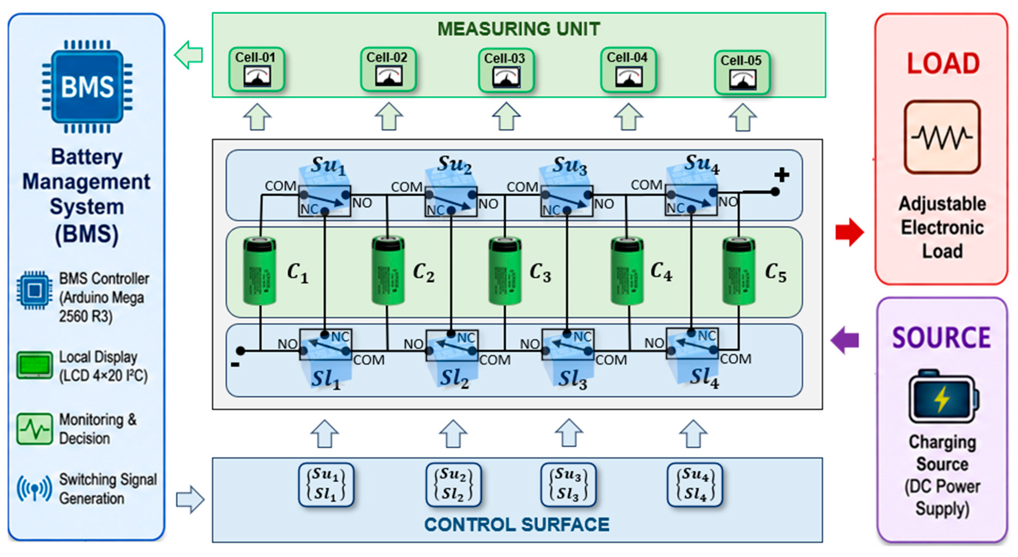
Figure 1 presents the conceptual architecture of the proposed five-cell implementation, while
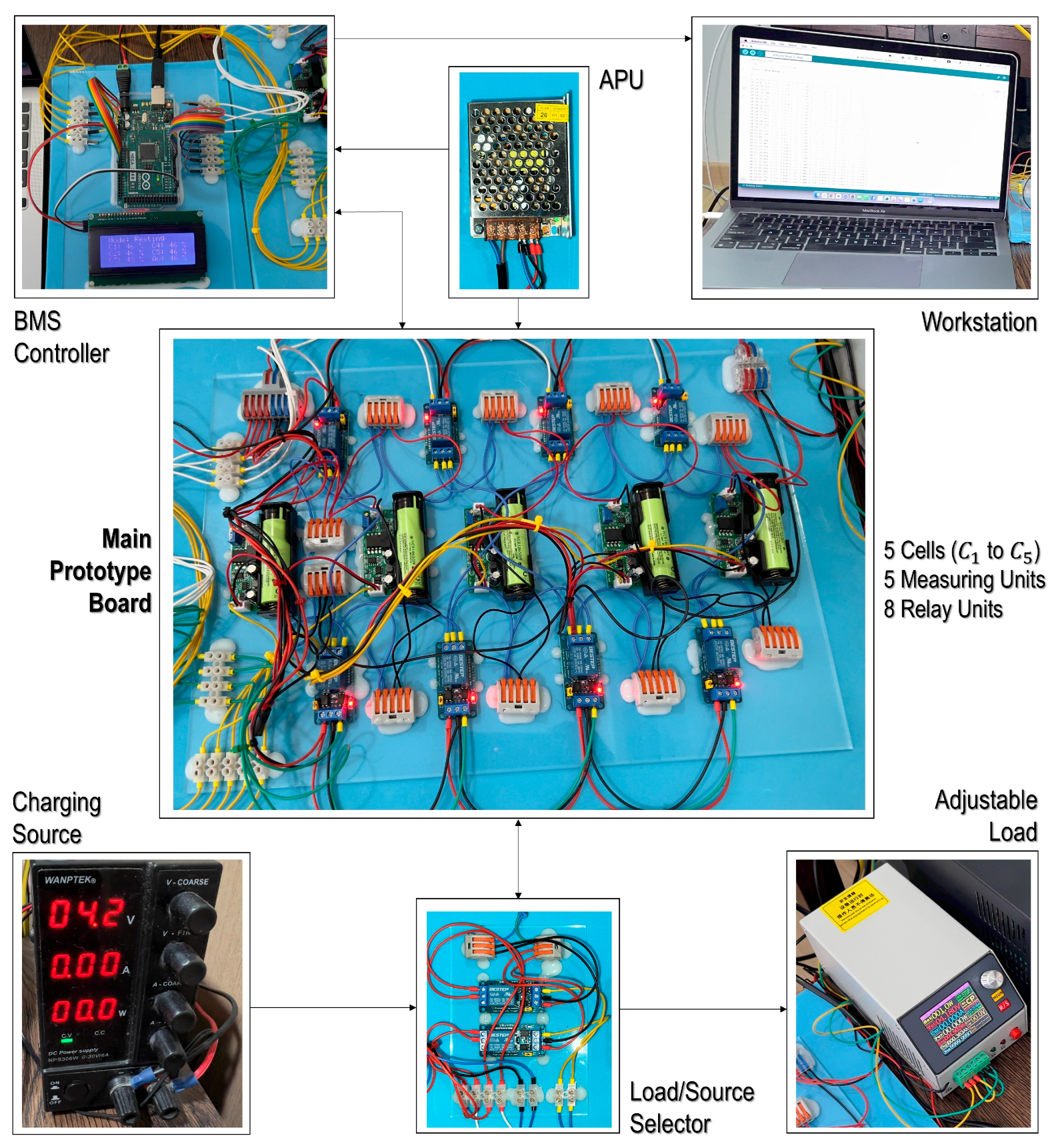
Figure 2 shows the assembled laboratory prototype.
The prototype consists of five Panasonic NCR18650PF lithium-ion cells interconnected through a relay-based switching matrix that enables dynamic modification of the electrical relationships among neighboring cells. In
Figure 1, those five cells are presented as C
1 (Cell-01) to C
5 (Cell-05). The switching network is formed using eight SPDT relays arranged between adjacent cells. Each intermediate cell is connected to one upper switch (Su) and one lower switch (Sl), allowing the battery pack topology to be reconfigured between series, parallel, and isolated operating states. The terminal cells require only single-sided switching connections due to their boundary positions within the battery string. This configuration preserves the hardware-efficient topology proposed in the simulation study while enabling practical implementation using commercially available components. As illustrated in
Figure 1, the control surface acts as the central decision-making unit responsible for determining and applying the switching configuration required by the balancing algorithm. Based on the measured condition of each cell, the controller generates relay actuation signals that establish the desired electrical interconnection pattern. Through controlled topology reconfiguration, the architecture promotes charge redistribution among cells without requiring dedicated balancing resistors, inductors, transformers, capacitors, or DC–DC converter stages.
The complete laboratory implementation shown in
Figure 2 comprises four principal subsystems: the battery management controller, the relay-based switching network, the voltage measurement subsystem, and the external charging and loading interfaces. The battery management controller is responsible for relay actuation, voltage acquisition, balancing logic execution, and data communication. The switching network performs the adaptive cell recombination process, while the measurement subsystem continuously monitors individual cell voltages throughout the experiments. Adjustable charging and loading equipment provide controlled operating conditions for evaluating balancing behavior during charging, discharging, and resting modes.
Since development of a novel state-of-charge estimation algorithm is outside the scope of this research, cell condition monitoring was performed using an open-circuit voltage (OCV)-based approach. Individual cell voltages were measured independently and subsequently converted into approximate SoC values using the manufacturer-provided characteristics of the Panasonic NCR18650PF cells. To prevent electrical interaction between the measurement circuitry and the battery pack, Broadcom HCNR201 linear analog optocoupler modules were employed for signal isolation. Electrical isolation was particularly important because the battery topology changes continuously during recombination operation, making conventional common-ground voltage measurement approaches unsuitable. The isolated measurement architecture additionally prevented unintended balancing currents from flowing through the sensing circuitry and improved measurement stability during relay transitions.
A dedicated auxiliary power unit (APU) was incorporated to supply power to the controller, relay modules, sensing circuits, and local display independently of the experimental battery pack. Separating the auxiliary electronics from the test cells ensured that all observed energy redistribution originated solely from the adaptive recombination process rather than auxiliary system power consumption. This arrangement also improved repeatability by eliminating parasitic loading effects from the balancing analysis.
The hardware components used in the prototype are summarized in
Table 3, all of which were sourced from Kuala Lumpur, Malaysia. Panasonic NCR18650PF lithium-ion cells were selected because they were also employed during the preceding simulation study, enabling direct comparison between simulated and experimental results. Furthermore, the cells possess well-documented electrical characteristics and extensive deployment history in e-mobility applications [
131,
132,
133]. The electrical characteristics used during prototype development were verified against the manufacturer datasheet to maintain consistency between the modeling and experimental phases.
The switching network was implemented using Bestep JQC3F optocoupler-isolated SPDT relay modules. Relay-based switching was selected primarily because it provided a practical and economically accessible method of implementing repeated topology reconfiguration during prototype development. Although solid-state switching technologies could offer faster operation and improved scalability, electromechanical relays provided clear switching states, straightforward implementation, and sufficient performance for proof-of-concept validation [
134,
135,
136].
The balancing controller was implemented using an Arduino Mega 2560 R3 microcontroller. The platform provides 54 digital input/output channels, 16 analog input channels, and 256 kB of flash memory, which exceeded the requirements of the experimental system. The available digital outputs enabled simultaneous control of all relay channels, while the analog inputs supported acquisition of multiple isolated voltage measurements. The controller additionally facilitated serial communication with the workstation computer and I2C communication with the local display module.
A 6 V switching power supply was used as the auxiliary power unit (APU). Charging experiments were performed using a Wanptek NPS306W programmable DC power supply, whereas discharging experiments utilized an MDL150 programmable electronic load. The electronic load supports constant-current (CC), constant-resistance (CR), and constant-power (CP) operating modes, enabling controlled evaluation of battery behavior under different operating conditions. Adjustable protection limits incorporated within the load also provided an additional safety layer during extended experimental operation.
Although the adaptive recombination topology requires only 2N − 2 SPDT switching elements for an N-cell battery string, this expression refers only to the core recombination switching network. It does not represent the complete hardware requirement of a deployable BMS. A practical implementation also requires switch-driving circuitry, cell-measurement channels, controller input/output resources, auxiliary power, wiring and interconnects, and protection circuitry. Therefore,
Table 4 summarizes the system-level hardware complexity of the present prototype and distinguishes the core switching-network requirement from the supporting hardware required for laboratory operation and future scalable implementation.
As shown in
Table 4, the 2N − 2 term corresponds to eight SPDT relay channels and eight driver channels in the present five-cell prototype. The controller also required N analog input channels per cell-profile measurement data acquisition and 2N − 2 digital output channels for relay actuation. In addition, isolated measurement units, auxiliary power, wiring, and interconnection hardware were required for prototype operation. These supporting elements are not unique to the proposed architecture, since practical balancing systems also require sensing, driver, controller, and interconnection hardware. Therefore, the 2N − 2 expression interprets as the switching-network requirement only, not as the complete system-level hardware requirement of an automotive BMS. The main hardware advantage of the proposed architecture is therefore that the balancing recombination network avoids dedicated balancing converters, inductors, transformers, and switched-capacitor energy-transfer stages while maintaining a low switching-network count. Future practical implementation scope will require embedded BMS electronics, solid-state switching devices, integrated protection circuitry, safety-rated PCB design, and pack-level auxiliary power.
Overall, the developed prototype successfully translated the previously simulated adaptive recombination architecture into a functional hardware platform. The resulting system provided a flexible experimental environment for investigating balancing behavior under realistic operating conditions while preserving the fundamental hardware-light philosophy of the proposed balancing strategy.
3.3. Cell Selection and Screening
The selection and characterization of experimental cells represent a critical stage in battery-balancing research because cell condition directly influences balancing dynamics, voltage equalization behavior, and energy redistribution characteristics. Variations in capacity, internal resistance, self-discharge rate, and degradation state can significantly affect balancing performance, potentially obscuring the true behavior of the balancing architecture under investigation [
15,
137,
138,
139,
140,
141,
142,
143]. Consequently, a systematic screening process was conducted prior to prototype implementation to ensure that the selected cells exhibited closely matched electrical characteristics while maintaining consistency with the cell model used in the previous simulation study.
Panasonic NCR18650PF lithium-ion cells were selected for this research because the same cell model was employed during the MATLAB/Simulink investigation reported in the authors’ previous work. Utilizing the same cell type enabled direct comparison between simulation and hardware validation results while maintaining consistency in cell chemistry, nominal capacity, voltage characteristics, and operating limits. The NCR18650PF is a commercially established cylindrical 18650-format lithium-ion cell with a nominal voltage of 3.6 V and rated capacity of 2700 mAh. Owing to its favorable balance between energy density, power capability, and cycle life, the cell has been widely deployed in e-mobility and energy-storage applications [
144,
145]. Furthermore, the availability of comprehensive manufacturer performance data [
131,
132,
133] facilitated development of the simulation model and subsequent experimental verification.
The use of second-life Panasonic NCR18650PF lithium-ion cells introduces an acknowledged limitation because their electrochemical behavior may differ from that of pristine cells due to aging-related changes in capacity, internal resistance, and degradation mechanisms. Therefore, the experimental results obtained in this study have been interpreted as validation of the adaptive recombination architecture using aged NCR18650PF cells rather than as a direct representation of pristine-cell behavior. Nevertheless, extensive screening and matching procedures were performed to minimize uncontrolled variability among the selected cells and to establish a stable experimental platform for hardware validation.
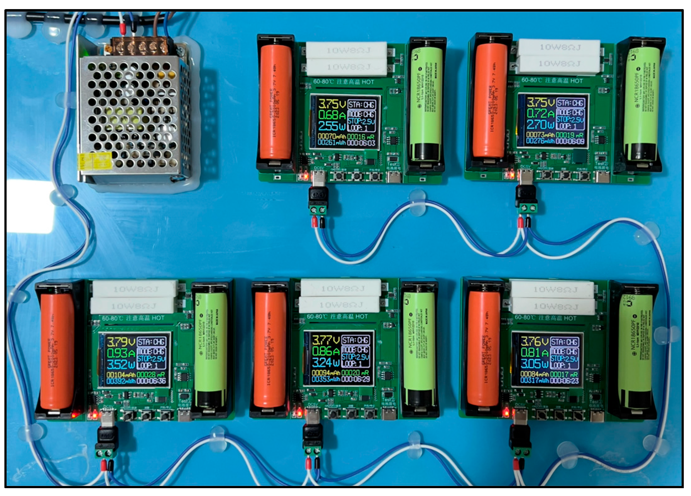
A dedicated battery analyzer was employed to characterize and compare fifty candidate cells, as shown in
Figure 3. The analyzer provided charge–discharge functionality together with measurements of internal resistance, accumulated discharge capacity, and accumulated discharge energy. Since the analyzer was a commercially available laboratory tool rather than a calibrated industrial battery characterization system, it was used primarily for comparative screening and relative cell matching rather than absolute electrochemical certification. This approach is commonly adopted in prototype-scale battery research where the objective is identification of closely matched cells rather than formal certification of battery performance parameters.
To ensure consistency, all characterization activities were performed at an ambient temperature of approximately 20 °C. Temperature control was considered important because lithium-ion battery performance parameters, particularly internal resistance and discharge capacity, are strongly influenced by operating temperature [
146,
147,
148]. Maintaining a stable testing environment therefore improved the repeatability and comparability of the screening results.
Each candidate cell was first charged to full capacity using the analyzer. Following completion of charging, direct-current internal resistance was measured. Internal resistance was selected as one of the primary screening parameters because it strongly influences voltage drop, current distribution, thermal behavior, and balancing current magnitude [
149,
150]. Cells exhibiting elevated resistance typically experience larger voltage deviations during operation and may introduce additional variability into balancing experiments [
151]. Consequently, close matching of internal resistance was considered essential for isolating the effects of the balancing architecture itself.
After resistance measurement, each cell underwent controlled discharge to a lower cut-off voltage of 2.5 V. During discharge, the analyzer recorded accumulated capacity and accumulated energy delivered by the cell. Capacity provides an indication of the charge-storage capability of the cell, whereas energy incorporates the influence of the voltage profile throughout the discharge process and therefore provides a more comprehensive representation of usable battery performance. The measured discharge capacity was subsequently compared with the manufacturer-rated capacity to estimate SoH for each candidate cell [
7,
152,
153].
Following completion of the characterization campaign, the five cells exhibiting the closest electrical characteristics were selected for integration into the prototype battery pack. The final selection criteria prioritized similarity in internal resistance, state-of-health, discharge capacity, and discharge energy. The characteristics of the selected cells are summarized in
Table 5.
As shown in
Table 5, the selected cells exhibited highly consistent characteristics, with measured internal resistance values of approximately 22 mΩ and state-of-health values ranging between 88% and 90%, which were the best similar health found among all fifty candidate cells. Accumulated discharge capacities varied from 2365 mAh to 2420 mAh, while measured discharge energies ranged from 8391 mWh to 8598 mWh. The relatively small variation among these parameters indicates successful matching of the selected cells despite their prior service history.
The screening process therefore established a controlled and repeatable experimental platform for subsequent hardware validation. Although the selected cells were not pristine, their closely matched electrical characteristics minimized uncontrolled variability and ensured that the observed balancing behavior was primarily attributable to the adaptive recombination architecture rather than significant differences in cell condition. The resulting cell set provided a suitable basis for evaluating the practical feasibility of the proposed balancing strategy under real hardware operating conditions.
3.4. SoC Monitoring Strategy
State-of-charge (SoC) estimation is one of the fundamental functions of a battery management systems (BMS) because it provides an indication of the remaining usable charge available within a battery cell relative to its maximum capacity [
154]. Accurate SoC information is important for balancing control, charge management, range prediction, and battery health assessment [
155,
156]. Although development of a novel SoC estimation methodology is beyond the scope of this research, reliable monitoring of individual cell conditions was necessary to support implementation and evaluation of the adaptive recombination balancing architecture.
During the simulation phase, cell SoC values were directly available from the battery models implemented within the MATLAB/Simulink environment [
25]. In the hardware prototype, however, SoC values had to be estimated from measured cell parameters. Several commonly adopted approaches were therefore evaluated during prototype development, including OCV estimation, coulomb counting, and hybrid estimation methods.
OCV-based estimation is among the most widely used approaches for lithium-ion batteries due to its simplicity and relatively good steady-state accuracy. In this method, the terminal voltage of a battery cell is measured after the cell has been electrically isolated and allowed to reach a sufficiently relaxed condition. The measured OCV is then mapped to a corresponding SoC value using manufacturer-provided or experimentally derived voltage-to-SoC characteristics [
157,
158]. For the Panasonic NCR18650PF cells used in this study, the manufacturer discharge characteristics were utilized to establish the voltage-to-SoC relationship. The general relationship can be expressed as Equation (1).
Here, represents the voltage-to-SoC mapping obtained from the manufacturer’s cell characteristics data.
The primary advantage of OCV-based estimation is that it does not require continuous current measurement or prior knowledge of the battery operating history. However, reliable OCV measurement requires sufficient voltage relaxation time following charging or discharging. Immediately after current flow ceases, lithium-ion cells exhibit transient voltage recovery caused by electrochemical polarization and surface charge effects. Consequently, direct voltage measurements obtained during active operation do not accurately represent the equilibrium state of the cell and may introduce significant SoC estimation errors [
154,
159,
160,
161,
162].
An alternative approach is coulomb counting, which estimates SoC by integrating battery current over time. Unlike OCV-based methods, coulomb counting enables continuous monitoring during charging and discharging operation [
154,
163,
164,
165]. The fundamental coulomb-counting relationship is given by Equation (2).
Here, denotes the initial state of charge, is the nominal cell capacity, and represents the cell current as a function of time.
Although coulomb counting provides continuous real-time SoC tracking, its accuracy depends heavily on the accuracy of the initial SoC value and the current measurement system. Small errors in current measurement, sensor drift, and uncertainty in battery capacity accumulate over time, causing increasing estimation error during prolonged operation. Consequently, coulomb counting is commonly combined with periodic OCV-based correction in practical battery management systems [
166,
167,
168,
169].
A hybrid OCV-coulomb-counting approach was initially considered during prototype development because it combines the steady-state accuracy of OCV estimation with the dynamic tracking capability of coulomb counting. Under such an approach, the initial SoC would be established from a relaxed OCV measurement and subsequently updated through current integration during operation. From a theoretical perspective, this methodology offers superior estimation performance compared with either method alone.
However, several practical limitations emerged during implementation. The experimental methodology required repeated creation of intentionally unbalanced cell conditions prior to each test case. As a result, the initial SoC distribution of the cells changed frequently throughout the experimental campaign. Implementing a hybrid approach would therefore require repeated reinitialization of the coulomb-counting system before each experiment, increasing both operational complexity and potential sources of error. Furthermore, accurate current monitoring of every dynamically reconfigured cell path would require additional sensing hardware that was not essential to the primary objective of the study, namely validation of the adaptive recombination balancing architecture.
Consequently, an OCV-based monitoring strategy was adopted for the prototype implementation. This decision was further supported by a unique characteristic of the proposed balancing architecture. Through the relay-based switching matrix, individual cells can be temporarily isolated from the remainder of the battery pack at any point during operation. This capability enabled controlled voltage-relaxation intervals followed by direct OCV measurement of each cell. After the predefined relaxation period, the measured OCV values were converted into the nearest SoC values using the Panasonic NCR18650PF voltage characteristics.
Although this approach increased the overall duration of the experiments because periodic relaxation intervals were required, it provided a practical and repeatable method of monitoring cell conditions without introducing cumulative integration errors. Since each measurement cycle was independently referenced to a fresh OCV observation, long-term drift associated with coulomb counting was eliminated. The resulting monitoring strategy therefore represented a suitable compromise between implementation simplicity, measurement reliability, and experimental repeatability.
Accordingly, OCV-based SoC monitoring was selected for all experimental investigations presented in this study. The approach provided sufficiently accurate cell-condition information for balancing control and performance evaluation while maintaining consistency with the practical constraints of the prototype platform.
3.5. Balancing Control Process
The adaptive recombination balancing architecture was implemented through a centralized control framework responsible for coordinating relay switching, cell-condition monitoring, and balancing-state updates throughout experimental operation. The control logic was designed to execute the balancing methodology [
25] described in
Section 3.1 while accommodating the practical constraints associated with a relay-based hardware implementation. Particular attention was given to switching synchronization, voltage measurement stability, and repeatable execution of the balancing process under charging, discharging, and resting conditions.
Unlike simulation environments, where switching actions occur instantaneously and measurements are assumed to be ideal, practical battery systems are subject to relay actuation delays, contact stabilization periods, voltage relaxation effects, and measurement uncertainty. Consequently, the control strategy incorporated dedicated timing intervals to ensure stable operation and reliable data acquisition during each balancing cycle.
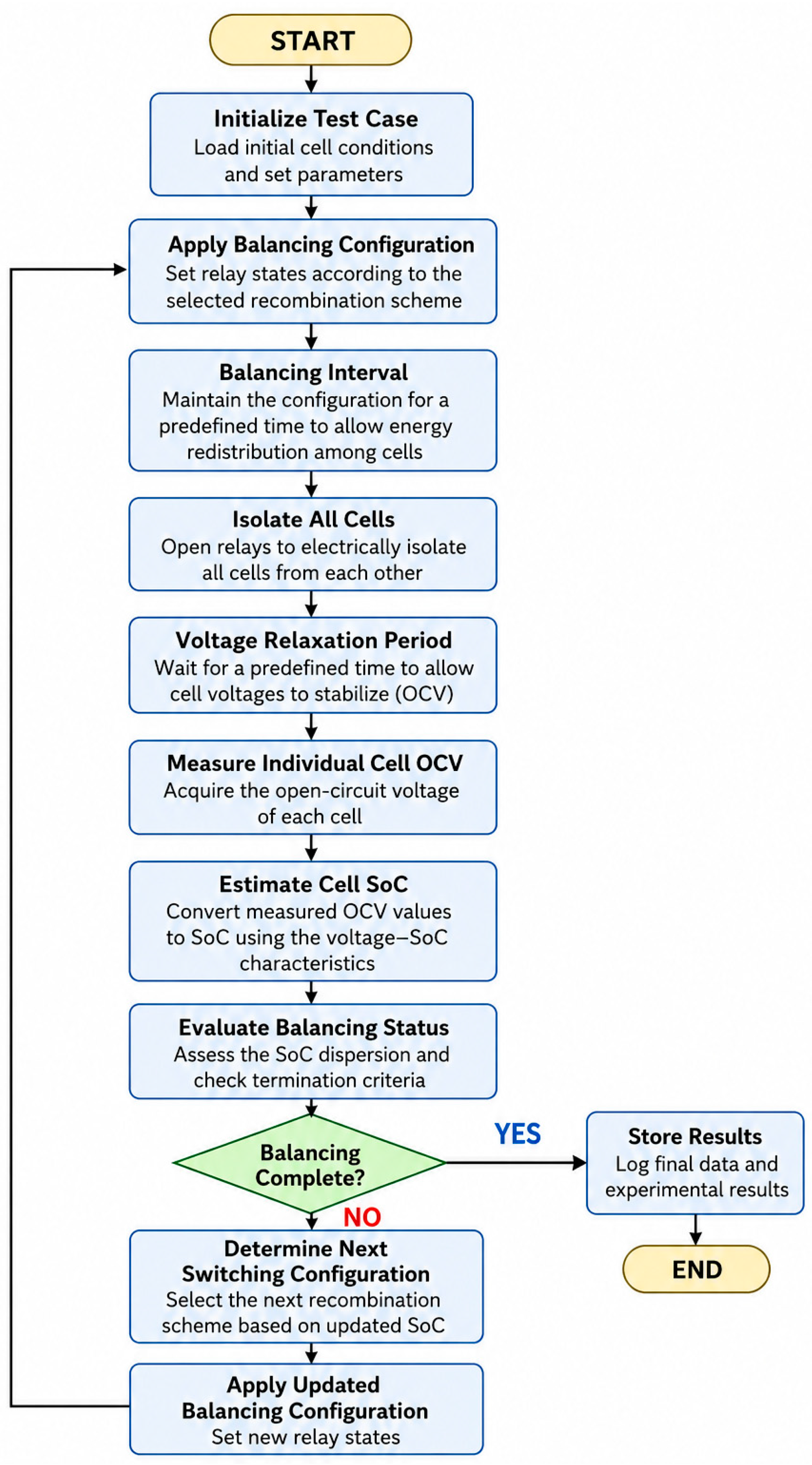
Figure 4 illustrates the operational sequence implemented within the prototype. At the beginning of an experiment, the balancing algorithm determines the appropriate switching configuration based on the initial cell conditions and immediately applies the corresponding relay states. The selected configuration remains active for a predefined balancing interval, allowing energy redistribution to occur through the established recombination pathways. Upon completion of the interval, all cells are temporarily isolated from one another through the switching matrix to eliminate transient current flow and prepare the system for voltage measurement.
Following isolation, the cells are allowed to remain in an open-circuit state for a predefined relaxation period. This stage is particularly important because lithium-ion cells exhibit temporary voltage recovery following charging or discharging due to electrochemical polarization effects. Allowing sufficient relaxation time improves the accuracy of OCV measurements and reduces uncertainty in the subsequent SoC estimation process. After the relaxation interval, the voltage measurement subsystem acquires the OCV of each cell individually. The measured voltages are then converted into approximate SoC values using the methodology described in
Section 3.4.
Once the updated cell conditions have been obtained, the controller evaluates the balancing status of the battery pack and determines whether the existing switching configuration should be maintained or replaced by a new recombination arrangement. The selected configuration is subsequently applied, and the balancing cycle is repeated until the termination criteria are satisfied. This periodic sequence of balancing, isolation, measurement, and decision-making forms the basis of the adaptive recombination control strategy implemented throughout the experimental campaign.
The balancing decision logic itself follows the adaptive recombination methodology established in the previous simulation study [
25]. Therefore, the detailed balancing algorithm, switching-state selection procedure, and recombination criteria are not repeated here to avoid redundancy. In general, the controller continuously evaluates the relative condition of all cells and dynamically selects electrical interconnection states that promote convergence toward equilibrium. The relay-based switching matrix enables these topology transitions without requiring dedicated energy-transfer converters or dissipative balancing circuits.
The control framework was implemented using an Arduino Mega 2560 R3 controller. The controller generated actuation signals for all eight SPDT relay channels while simultaneously acquiring voltage measurements from the isolated sensing modules. Measurement interval selection also played an important role in balancing performance evaluation. Excessively short intervals can capture transient voltage behavior rather than near-equilibrium conditions, whereas excessively long intervals increase experimental duration without providing significant advantages for data accuracy. In the present work, voltage measurements were intentionally performed only after completion of the predefined relaxation period to ensure that OCV values closely represented the electrochemical state of the cells. The ability of the adaptive recombination architecture to temporarily isolate individual cells significantly simplified this measurement process and enabled repeated acquisition of stable OCV measurements throughout all operating modes.
All cell voltages were measured through isolated HCNR201-based sensing modules. Prior to experimentation, each sensing channel was calibrated against a Sanwa CD800a digital multimeter to minimize offset and scaling errors. Electrical isolation was particularly important because the continuously changing battery topology prevented the use of conventional common-ground measurement techniques. The isolated measurement architecture additionally eliminated potential current leakage paths through the sensing circuitry and improved measurement stability during relay switching operations.
The primary objective of the prototype was to evaluate the intrinsic balancing behavior of the adaptive recombination architecture under controlled environment. Therefore, no dedicated protection circuitry was integrated directly into the prototype, thereby avoiding unintended interactions between protective functions and the balancing process. Nevertheless, several external safety mechanisms were incorporated within the experimental equipment. The programmable electronic load included configurable over-voltage, over-current, and over-power protection functions, while the programmable charging supply incorporated built-in current-limiting capability. Prior to experimental use, both instruments were calibrated against the reference multimeter to improve measurement consistency and operational reliability.
The implemented control framework therefore provided a stable and repeatable platform for experimental validation of the adaptive recombination balancing strategy. By combining synchronized relay operation, periodic cell isolation, OCV-based condition monitoring, and adaptive topology selection, the system enabled practical evaluation of the balancing architecture under realistic charging, discharging, and resting conditions while preserving consistency with the previously published simulation methodology.
3.6. Practical Implementation Considerations
The transition from simulation-based validation to physical hardware implementation revealed several practical considerations that are difficult to capture within an idealized modeling environment. While the adaptive recombination architecture demonstrated stable operation during simulation, development of the experimental prototype required addressing numerous challenges associated with cell procurement, measurement reliability, switching hardware, sensing architecture, and operational safety. These observations provide valuable insight into the practical realities of implementing reconfigurable battery-balancing systems and highlight considerations relevant to future large-scale deployment.
One of the most significant challenges encountered during prototype development was the procurement of suitable lithium-ion cells. Initially, the experimental validation was intended to be conducted using pristine Panasonic NCR18650PF cells to maintain close alignment with the simulation model and minimize variability associated with aging. However, obtaining genuine factory-grade cells in small research quantities proved impractical. During the procurement process, it was observed that Panasonic cylindrical lithium-ion cells are primarily distributed through industrial supply chains serving battery manufacturers, pack integrators, and commercial customers. Direct procurement for independent laboratory-scale research was generally unavailable through conventional channels. Although several alternative sourcing approaches were investigated, including acquisition through third-party suppliers and extraction from commercial battery products, obtaining verified pristine NCR18650PF cells in suitable quantities was not feasible. Consequently, second-life NCR18650PF cells were selected as the most practical alternative and subsequently subjected to extensive screening and matching procedures before integration into the prototype.
Another important consideration involved selection of a suitable SoC monitoring approach. From a theoretical perspective, hybrid OCV-coulomb-counting techniques offer superior estimation accuracy by combining voltage-based initialization with continuous current integration. During prototype development, several commercially available coulomb-counting solutions were evaluated for potential integration. However, practical implementation challenges emerged due to hardware compatibility limitations, proprietary interfaces, operating-voltage constraints, and difficulties associated with monitoring dynamically changing current paths within the reconfigurable battery architecture. Furthermore, repeated creation of intentionally unbalanced cell conditions throughout the experimental campaign would have required frequent reinitialization of the coulomb-counting system, significantly increasing operational complexity. As a result, OCV-based monitoring was ultimately adopted as the most practical and reliable solution for the prototype implementation.
Selection of the switching technology also required careful consideration. Solid-state switching devices offer advantages in switching speed, durability, and scalability; however, suitable devices capable of supporting the intended experimental configuration were not readily available within the practical constraints of the project. Consequently, electromechanical SPDT relays were selected for implementation of the switching matrix. Although relay-based switching introduces finite actuation delays, contact resistance variation, and mechanical wear, it provided a straightforward and reliable means of implementing repeated topology reconfiguration during proof-of-concept validation. The electromechanical SPDT relays used in this prototype were selected only for proof-of-concept validation because they allowed the recombination states to be implemented and observed using commercially available hardware. They are not proposed as the final switching technology for EV-grade implementation. Automotive-scale realization would require solid-state switching devices with controlled dead time, short-circuit prevention, thermal management, vibration tolerance, and verified switching-loss performance.
Voltage measurement presented another practical challenge due to the continuously changing electrical topology of the battery pack. Conventional voltage sensing approaches typically rely on a common electrical reference, which becomes problematic when cell interconnections are repeatedly modified during operation. Several sensing approaches were evaluated before the HCNR201-based isolated analog measurement architecture was selected. The use of isolated sensing modules eliminated grounding conflicts, reduced measurement interference, and prevented unintended current leakage through the measurement circuitry. This isolation capability proved particularly valuable because individual cells continuously changed their electrical reference positions as the balancing algorithm altered the pack topology.
Voltage relaxation behavior emerged as one of the most influential practical factors affecting measurement reliability. Experimental observations confirmed that immediately measured terminal voltages often differed significantly from the stabilized open-circuit voltages required for reliable SoC estimation. Following charging or discharging, the cells exhibited measurable voltage recovery caused by electrochemical polarization and surface charge effects. Several relaxation intervals were evaluated during preliminary testing, and it was observed that the selected cells exhibited relatively small voltage differences between measurements obtained after approximately 3 h and substantially longer relaxation periods. Consequently, a 3 h relaxation interval was adopted as a practical compromise between measurement accuracy and experimental duration. This observation further reinforced the importance of incorporating dedicated relaxation intervals into the control framework described in
Section 3.5. Although a 3 h relaxation interval was adopted in this prototype to obtain stable OCV-based reference values, this procedure is not intended for real-time EV BMS implementation. The relaxation-based measurement strategy was used only as a laboratory method to reduce uncertainty during proof-of-concept validation of the recombination mechanism. In a deployable BMS, the proposed balancing architecture would require real-time SoC estimation through current sensing, coulomb-counting, voltage correction, observer-based estimation, or hybrid SoC/SoH algorithms. Therefore, the present study validates only the physical balancing behavior of the adaptive recombination architecture, while real-time SoC estimation remains outside of scope as mentioned in
Table 2, which is a required future-development scope for automotive implementation.
The prototype development process also highlighted several practical considerations associated with human errors. During early experimentation, an accidental reverse-polarity installation occurred while configuring an all-parallel cell arrangement. Because the prototype intentionally excluded embedded protection circuitry to allow direct observation of balancing behavior, a large equalization current immediately developed between the cells, resulting in localized overheating and damage to several prototype components before manual intervention could occur. Although the affected components were subsequently replaced, the incident demonstrated the importance of fault protection, polarity verification, and current-limiting mechanisms in future implementations. It also provided a practical reminder that reconfigurable battery systems can generate substantial transient currents when significant voltage differences exist between interconnected cells. In another pre-experimental incident, it has been observed that over discharging a cell for longer time can cause health degradation in short-term operation which led to permanent damage of the cell in long-term over discharging, resulting in the cell to be unable to re-increase the SoC anymore.
The reverse-polarity and over-discharge incidents were observed during early prototype testing, before the formal experimental campaign began. These observations motivated the implementation of several safety measures, including break-before-make switching control, over-voltage and under-voltage cut-off conditions, and fault-status logic to prevent recombination under unsafe cell conditions or reverse-polarity conditions. In addition, over-current protection limits were configured in both the source and load settings, and basic laboratory safety precautions were maintained throughout the experiments. As a result, no safety-related incidents occurred during the formal experimental test cases. Although these measures were sufficient for controlled laboratory operation, the present prototype still requires further hardware-level safety enhancement, including cell-level fusing, individual cell-current monitoring, temperature monitoring, and dedicated protection circuitry, which are within the future scope of this research. Automotive-grade safety design and validation remain outside the scope of this first-stage proof-of-concept prototype, but will be required for actual EV deployment.
Determination of reliable charging and discharging termination conditions represented another important engineering consideration. Experimental observations indicated that the most consistent method of identifying full-charge conditions was to follow the manufacturer-recommended constant-current constant-voltage (CC-CV) charging profile and monitor current tapering behavior during the constant-voltage stage. For the Panasonic NCR18650PF cells used in this study, charging was considered complete when the charging current naturally decreased to approximately 0.05 C, corresponding to approximately 135 mA. Similarly, discharge termination was performed in accordance with the manufacturer-specified lower-voltage limit of 2.5 V to avoid excessive degradation and potential cell damage.
Several additional practical factors influenced prototype operation, including voltage measurement noise, minor thermal fluctuations, and transient voltage disturbances immediately following topology transitions. While these effects were absent from the simulation environment, they are representative of conditions encountered in real battery systems and therefore constitute an important aspect of the hardware validation process. Despite these non-idealities, the prototype consistently demonstrated stable operation throughout the experimental campaign and successfully validated the practical feasibility of the adaptive recombination balancing architecture.
Overall, the implementation considerations identified during prototype development emphasize the challenges associated with translating a balancing concept from simulation into physical hardware. At the same time, they provide valuable engineering insight for future development of larger-scale adaptive recombination systems employing higher-current operation, advanced sensing architectures, automated state estimation, solid-state switching technologies, and enhanced safety mechanisms with dedicated components instead of relying on commercially available ones.
For practical deployment, the recombination architecture must incorporate protection functions that were not integrated into the present proof-of-concept prototype. These include cell-level fusing, pre-charge or soft-start circuitry, current limiting, polarity detection, over-voltage and under-voltage protection, over-current protection, thermal monitoring, transient-current suppression, and break-before-make switching logic. These protection functions are essential because the transient current during recombination depends on the voltage difference between interconnected cells and the total resistance of the current path.
4. Experimental Methodology
4.1. Experimental Framework
The experimental methodology was developed to validate the adaptive recombination-based cell-balancing architecture under practical operating conditions using a physical hardware prototype. Unlike the previously published simulation study, the present investigation incorporates real lithium-ion cells, electromechanical switching devices, measurement circuitry, wiring losses, voltage relaxation effects, and other non-ideal characteristics inherent to physical battery systems. The objective was to evaluate whether the balancing behavior predicted by simulation could be reproduced experimentally while identifying implementation-specific phenomena that influence balancing performance.
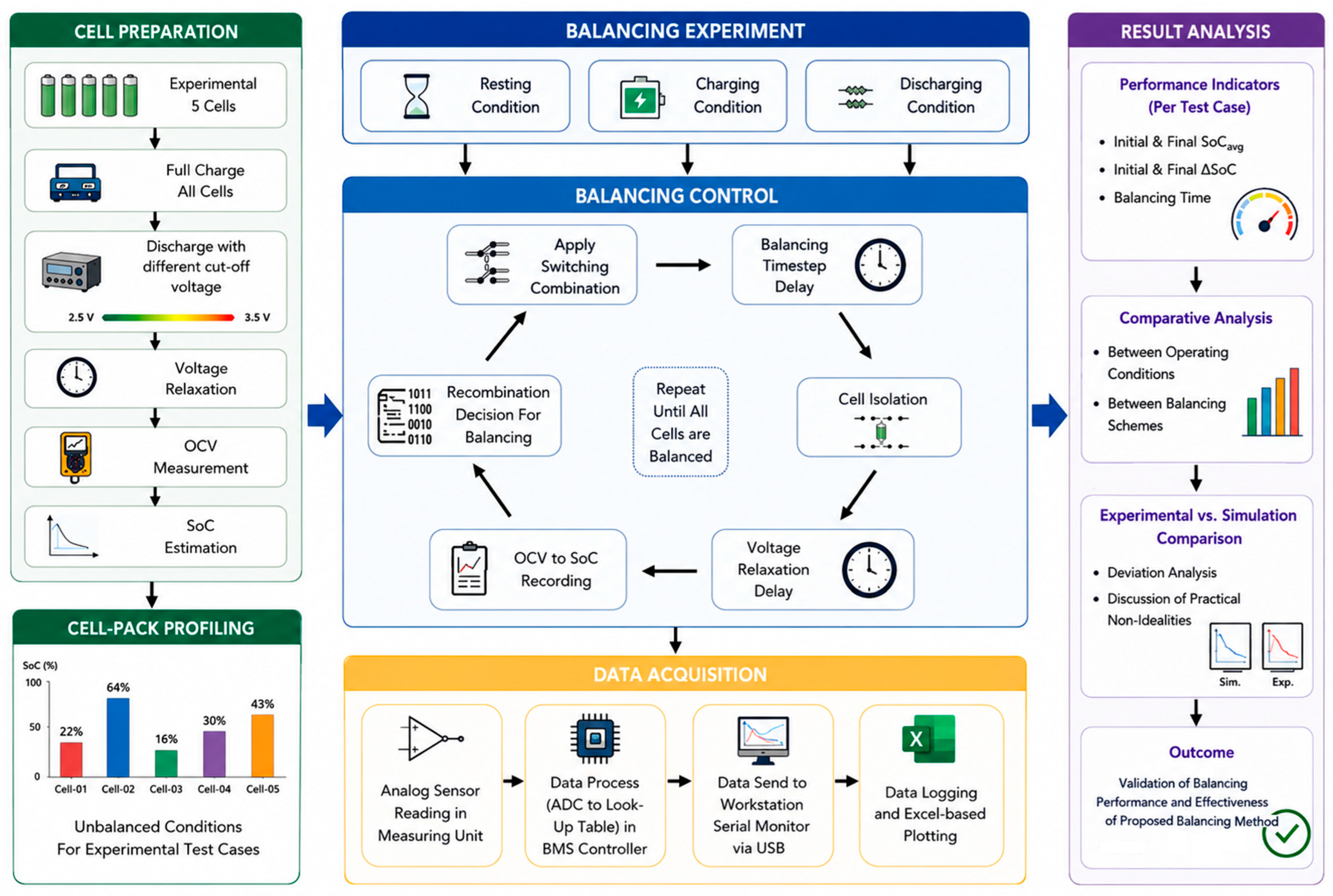
The overall experimental workflow is illustrated in
Figure 5. The methodology consisted of three sequential stages: (i) preparation of intentionally imbalanced cell conditions and cell-pack profiling with unbalanced cells; (ii) execution of balancing experiments and data collection; (iii) analysis and evaluation of all experimental results. To ensure consistency across all investigations, the same hardware platform, balancing control logic, switching sequence, voltage measurement architecture, and SoC estimation approach were maintained throughout the experimental campaign. Experimental validation was performed under three operating modes representing practical battery usage conditions: resting, charging, and discharging. Within each operating mode, two balancing schemes were evaluated to compare their balancing effectiveness and convergence behavior, resulting in a total of six different experimental test cases in this study.
4.2. Experimental Cell Conditioning
Prior to each experiment, the selected Panasonic NCR18650PF lithium-ion cells were conditioned to establish controlled and repeatable initial imbalance conditions. The technical specifications of the Panasonic NCR18650PF cells used throughout the investigation as well as the experimental setup configurations for the cell in all experimental test cases are summarized in
Table 6.
The charging and discharging configurations presented in
Table 6 was selected to provide controlled laboratory operating conditions for evaluating the balancing behavior of the prototype. The DC power supply used in the experiment has a maximum output capability of 30 V and 6 A, as listed in
Table 3; however, it was configured with a voltage setpoint of 4.2 V and a current-limit ceiling of 2.5 A during the charging-condition tests. The 4.2 V value represents the external source voltage limit, whereas the prototype controller used the Load/Source Selector shown in
Figure 2 to disconnect the charging source when the monitored cell voltage reached the configured prototype charging cut-off voltage of 4.08 V. Therefore, the 4.08 V value in
Table 5 represents the cut-off threshold applied by the prototype controller during this proof-of-concept experiment, while the 4.2 V value represents the source voltage setpoint required to maintain a voltage-limited charging condition.
The charging source was operated as a CC-CV capable laboratory power supply with a voltage setpoint and a current-limit ceiling. Under this operating principle, if the current demand of the connected cell network exceeds the configured 2.5 A current limit, the source automatically reduces its output voltage to maintain the current limit and enters current-limiting CC operation. When the current demand falls below the configured limit, the source returns to voltage-regulated CV operation by raising the output voltage back toward the configured voltage setpoint.
During the experimental test cases, the current demand did not exceed the 2.5 A limit; therefore, the source remained in voltage-regulated operation and a CV-only charging behavior was observed in all test cases. The 2.5 A setting was used as an upper current-limit ceiling for safe laboratory operation of the prototype wiring and relay network, rather than as a commanded constant charging current.
Similarly, the prototype discharging cut-off voltage was set to 2.5 V in accordance with the lower-voltage limit used for the experimental cells. During discharging tests, the programmable load was operated in constant-power mode at 1 W, with its built-in over-current protection set to 2.5 A to interrupt the discharge process if the current exceeded the configured safety limit. This over-current condition was also not observed during the experiments. These voltage and current settings were used as laboratory protection limits for the proof-of-concept prototype and should not be interpreted as an optimized automotive charging or discharging strategy.
Cell conditioning was performed using the battery analyzer discussed in
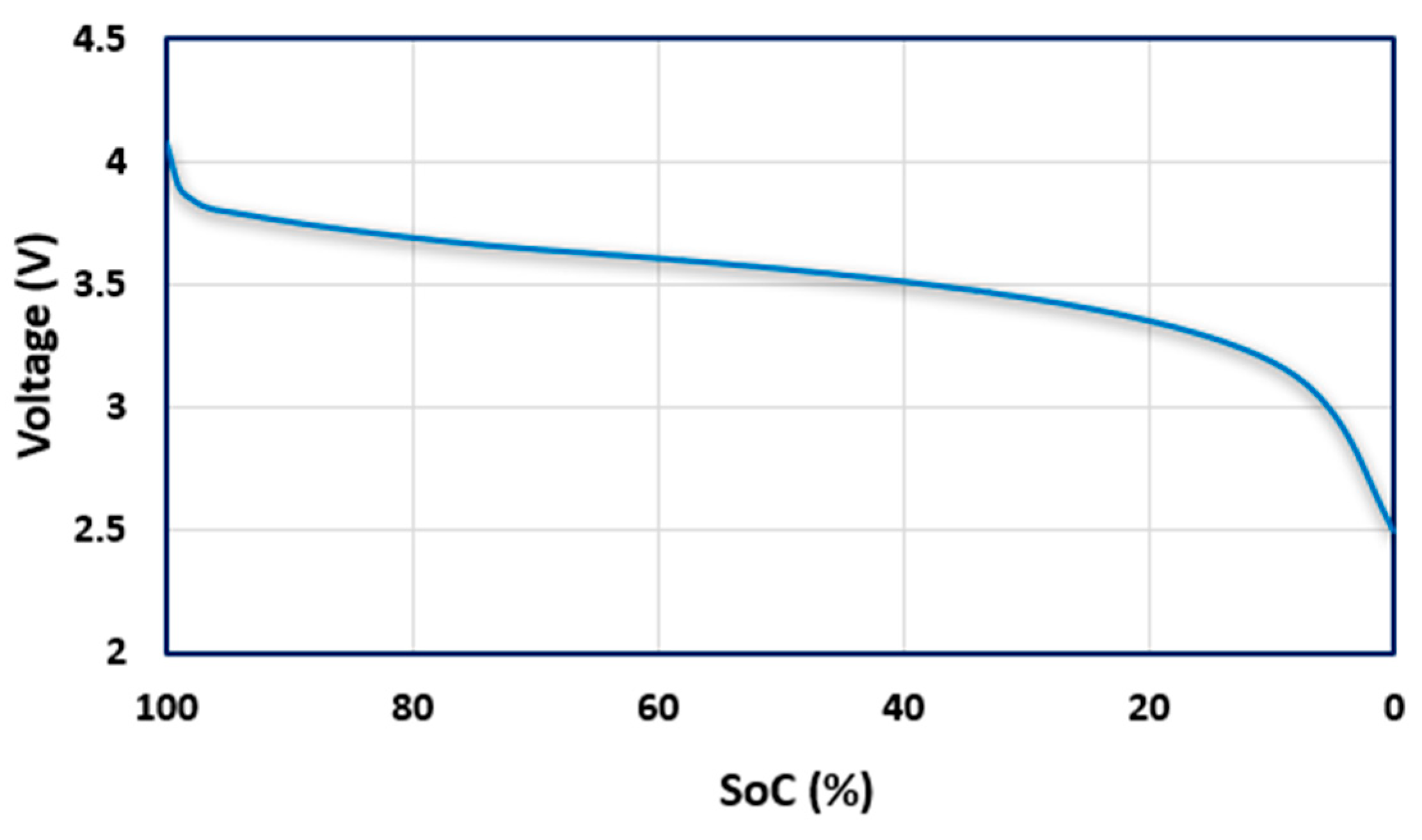
Section 3.3. Initially, all cells were charged to full capacity. Controlled discharge procedures were then applied individually to each cell to create the desired SoC distribution required for a particular test case. Following discharge, the cells were allowed to remain in an open-circuit condition for approximately three hours to permit voltage relaxation and stabilization. The stabilized open-circuit voltage (OCV) of each cell was subsequently measured using a calibrated digital multimeter and converted into corresponding SoC values using the manufacturer-derived OCV-SoC relationship data. The use of relaxed OCV measurements improved repeatability by minimizing transient polarization effects associated with recent charging or discharging activity. The resulting SoC values were used as the initial conditions for all balancing experiments.
Figure 6 presents the voltage-versus-SoC characteristic utilized during OCV-based SoC estimation. The nonlinear relationship shown in
Figure 6 highlights the importance of stabilized OCV measurements when estimating SoC. This characteristic was incorporated into the monitoring methodology described previously in
Section 3.4 and was consistently applied throughout all experiments.
4.3. Test Matrix Design
A structured experimental test matrix was developed to evaluate the balancing performance of the proposed architecture under different operating conditions and balancing strategies. Six experimental test cases were designed, comprising two balancing schemes evaluated under three operating modes. The complete test matrix is summarized in
Table 7. The three operating modes were selected to represent practical battery usage scenarios: (i) resting condition, where balancing occurs solely through electrochemical equalization; (ii) charging condition, where balancing occurs simultaneously with external energy injection; (iii) discharging condition, where balancing occurs while energy is extracted from the battery pack.
For each operating mode, two balancing schemes were investigated: scheme A and scheme B. Scheme A represents sequential balancing, which follows the original priority-based balancing approach proposed in the simulation study. The controller identifies the highest-priority imbalance and performs balancing sequentially until the deviation falls within the predefined tolerance before proceeding to the next priority condition. And, scheme B represents simultaneous balancing, which permits all participating cells to engage in the balancing process simultaneously through collective recombination pathways. This arrangement promotes concurrent charge redistribution throughout the balancing operation.
The initial SoC distributions used for each test case are presented in
Table 8. The Initial SoC imbalance ranges from 45% to 55% due to the technical capability limitation of the cell-analyzer hardware of
Figure 3, which has been used to set initial SoCs of each cell for all test cases, as presented in the cell preparation process in
Figure 5. Although every effort was made to establish nearly identical initial imbalance conditions between corresponding Scheme A and Scheme B test cases, exact initial SoC replication could not be achieved because of cell relaxation, OCV hysteresis, conditioning variability, and second-life cell behavior.
As shown in
Table 8, the paired initial ΔSoC differences between Scheme A and Scheme B were 3% under resting conditions, 1% under charging conditions, and 3% under discharging conditions. These differences indicate that the initial imbalance levels were sufficiently similar for proof-of-concept comparison, particularly when interpreted together with the normalized time per 1% SoC deviation reduction. The six experiments were conducted sequentially to verify measurement-channel stability, controller functionality, and consistent prototype operation throughout the study. However, owing to the long balancing duration of several test cases, full experimental replication was not performed. Therefore, the results should be interpreted as proof-of-concept evidence rather than as a statistically replicated performance benchmark. Future work will include repeated experiments with tighter initial-condition control and statistical error analysis.
4.4. Experimental Configuration, Data Acquisition, and Performance Evaluation
The resting-condition experiments (Test Cases 01 and 02) were conducted without any external charging source or discharge load. Charging experiments (Test Cases 03 and 04) were performed using the programmable DC power supply. As presented in
Table 6, the charger operated in constant-voltage mode using the manufacturer-recommended charging voltage corresponding to 4.2 V per cell for a relatively low-charging current. The charging current was intentionally maintained at a low value to remain within the safe operating limits of the prototype wiring and relay network. Discharging experiments (Test Cases 05 and 06) were conducted using the programmable electronic load operating in constant-power mode. A low discharge power of 1 W was also selected to ensure safe operation while maintaining measurable balancing activity throughout the experiments. Under these conditions, energy redistribution occurred solely through the adaptive recombination pathways established by the balancing controller with negligible amount of heat losses due to wire resistance. All experiments were performed under 20 °C of room temperature. The same switching sequence, measurement procedure, and balancing control methodology were maintained across all operating modes to ensure consistency of the experimental results.
Throughout each experiment, individual cell voltages were continuously acquired through the isolated measurement subsystem described in
Section 3.2. The measured voltages were converted into corresponding SoC values using the OCV-based methodology described in
Section 3.4. The controller transmitted measurement data to a workstation computer through serial communication, where the information was logged continuously for subsequent analysis. The recorded datasets were subsequently processed using spreadsheet software to generate balancing profiles and performance comparisons. Balancing performance was evaluated using five primary metrics: (i) Average SoC; (ii) SoC deviation; (iii) Balancing Time; (iv) Time Per Deviation; and (v) Balancing Speed-Up Ratio. The average pack SoC for N number of cells (
) was calculated with Equation (3). SoC deviation is the difference between initial and final balancing errors (
) as defined by Equation (4), where the initial and final ΔSoC represent the highest (
) and lowest (
) cell SoC values in the pack as defined by Equation (5).
The initial imbalance condition before balancing process starts, is quantified as the initial ΔSoC (), and the final balancing error after completing the balancing process is quantified as final ΔSoC (). The SoC deviation () is the difference between the initial and final ΔSoCs, which quantify how much balancing error has been reduced by the cell-balancing model prototype during the balancing process. Balancing time () was defined as the elapsed duration required for all cells to satisfy the balancing termination criterion implemented by the controller. Time Per Deviation () is the amount of time taken by the prototype for each 1% SoC balancing error reduction, as defined by Equation (6). And the balancing speed-up ratio () refers to how fast the simultaneous balancing schemes () was in compared to the sequential balancing schemes () in each experimental test cases, as defined by Equation (7). These metrics were subsequently used to compare balancing performance across operating modes, evaluate the relative effectiveness of the two balancing schemes, and assess agreement between experimental and simulation results.
To assess measurement reliability, the voltage acquisition system was calibrated prior to experimentation using a Sanwa CD800a digital multimeter as the reference instrument. Following calibration, the residual measurement deviation of the HCNR201-based sensing channels remained within approximately ±0.01 V across the operating voltage range of the experimental cells. The manufacturer-specified accuracy of the reference multimeter is approximately ±0.7% in the relevant DC voltage range. Additional uncertainty originates from the OCV-to-SoC conversion process because the Panasonic NCR18650PF voltage–SoC characteristic exhibits nonlinear behavior, particularly within the relatively flat mid-SoC region. Based on the resolution of the adopted OCV–SoC relationship and the observed voltage stability after the relaxation period, the resulting SoC estimation uncertainty was estimated to be within approximately ±1–2% SoC. Since the primary objective of this study was cell-balancing behavior evaluation rather than absolute determination of SoCs, these uncertainty levels were considered acceptable and did not materially affect interpretation of the experimental results.
4.5. Experimental Assumptions and Limitations
Several assumptions were maintained throughout the experimental campaign. First, the investigation was conducted using screened and matched second-life Panasonic NCR18650PF cells rather than pristine cells. Second, SoC estimation was based on OCV measurements rather than advanced model-based estimation techniques. Third, balancing was implemented using electromechanical SPDT relays, which may result in minor switching delays or contact arcing that are absent in ideal simulation environments. Fourth, all experiments were performed under ambient room conditions without active thermal control. Fifth, all SoC measurements were in 0 decimal points due to measuring hardware limitations, unlike the simulation environment where it was in two-decimal-point reading. Finally, relatively low charging and discharging currents were employed to remain within the safe operating limits of the prototype hardware. These constraints define the scope of the present experimental validation and will be considered when interpreting the experimental results.
5. Results and Analysis
The experimental balancing performance of the adaptive recombination prototype was evaluated under resting, charging, and discharging conditions using six test cases. The resulting balancing characteristics are summarized in
Table 9. Complete equalization was achieved in all experimental cases within the measurement resolution of the prototype, rather than as an absolute zero-error condition. Although balancing time varied significantly between operating modes and balancing schemes, the overall balancing tendencies remained consistent with those predicted by the previously published simulation results.
Table 9 summarizes the principal performance metrics obtained from all experimental investigations. Initial SoC imbalance ranged from 45% to 55%, representing substantially unbalanced battery conditions. Following execution of the adaptive recombination algorithm, all test cases converged to a fully balanced state. The balancing time varied considerably depending on operating condition and switching scheme, indicating that both external operating mode and recombination strategy strongly influence balancing effectiveness.
The results indicate that the relative performance of the balancing schemes depends on operating condition. Simultaneous balancing (Scheme-B) provided the fastest balancing under resting and discharging conditions, whereas sequential balancing (Scheme-A) produced superior performance during charging operation. These observations are analyzed in the following sections.
5.1. Balancing Performance Under Resting Conditions
The balancing results obtained under resting conditions are presented in
Figure 7 and
Figure 8 for Scheme-A and Scheme-B, respectively. In both cases, no external charging source or discharge load was connected and balancing occurred exclusively through adaptive the cell recombination model charge redistribution capability.
The sequential balancing (Scheme-A) of resting condition in Test Case-01 as presented in
Figure 7, the cells initially exhibited SoC values between 16% and 64%, corresponding to an initial imbalance of 48%. The balancing process gradually redistributed energy among the cells until the cell SoC values converged within the measurement resolution of the prototype at approximately 34% average SoC after 2400 min. The result confirms that the adaptive recombination architecture can achieve full balancing solely through controlled cell interconnection.
In Test Case-02, which is the simultaneous balancing (Scheme-B) of resting condition as presented in
Figure 8, the initial SoC imbalance was 45%, and convergence within the measurement resolution of the prototype was achieved after 330 min. Compared with Scheme-A, Scheme-B reduced balancing time by approximately 86.3%, corresponding to a reduction from 50.0 min/%ΔSoC to 7.3 min/%ΔSoC.
The results demonstrate a substantial advantage of simultaneous balancing under resting conditions. Allowing multiple cells to participate concurrently in the redistribution process increased the effective balancing current and accelerated convergence toward equilibrium. Although the absolute balancing times differed from the previously reported simulation results, the experimentally observed trend remained consistent, with Scheme-B outperforming Scheme-A.
5.2. Balancing Performance Under Charging Conditions
The balancing results obtained during charging operation are presented in
Figure 9 and
Figure 10. In Test Case-03, the initial SoC imbalance was 47%. During charging, lower-SoC cells gradually converged toward the highest initial SoC level, and the cells reached a balanced condition within the measurement resolution of the prototype after 68 min, with a final average SoC of approximately 62%. The result closely follows the balancing behavior predicted by the simulation model. Under charging conditions, the adaptive recombination strategy preferentially increases the SoC of lower-energy cells while maintaining continuous charging of the battery pack.
In Test Case-04, the balancing process occurred while all cells simultaneously participated in charge redistribution. The cell-current () of the highest-SoC cell, which is Cell-02 in this test case, may be expressed as Equation (8), where the balancing current () is the net amount of current Cell-02 is feeding to rest of the cells as all of those are in lower potential than Cell-02 as expressed by Equation (9), while receiving charging current () at the same time.
Similarly, the current relationship of the lowest-SoC cell, which is Cell-03 in this test case, can be represented by Equation (10), where the cell-current (I
C3) of Cell-03 is receiving charging current (
) as well as balancing current (
) from all other cells as it is the lowest-SoC cell, which has been expressed as Equation (11). Following the same principle, the balancing current relationship for any middle-SoC cell (
) can be expressed by Equation (12). Such a cell simultaneously receives balancing current from cells having a higher SoC and supplies balancing current to cells having a lower SoC. Therefore, the net cell current (
) of any cell (
) from Cell-01 (
) to Cell-05 (
) will be equal to its charging current plus the total incoming balancing current minus the total outgoing balancing current expressed by Equation (13).
Unlike the simulation results, the highest-SoC cell did not exhibit an initial decrease in SoC. Instead, its SoC increased continuously throughout the balancing process, indicating that the balancing current remained lower than the charging current supplied by the external source. A balanced condition within the measurement resolution of the prototype was achieved after 120 min, which was slower than the 68 min required by Scheme-A. Consequently, Scheme-B underperformed Scheme-A during charging operation, representing the only operating condition where the experimental results differed from the performance ranking predicted by simulation. This observation suggests that simultaneous balancing under charging conditions is more sensitive to practical current-sharing behavior and non-ideal cell characteristics.
5.3. Balancing Performance Under Discharging Conditions
The balancing results obtained under discharging conditions are presented in
Figure 11 and
Figure 12. In Test Case-05, the cells initially exhibited a 55% SoC imbalance. The adaptive recombination strategy progressively reduced the energy of higher-SoC cells until the cell SoC values converged within the measurement resolution of the prototype near the lowest initial SoC level. The balancing process required 262 min. The observed behavior closely matched the simulation predictions, confirming that the balancing strategy remains effective during active discharge operation. Following the same principle described for Equation (12) in charging operation cell-balancing, the balancing current relationship (
) of any cell (
) from Cell-01 (
) to Cell-05 (
) in discharging condition, will be equal to its total incoming balancing current minus the total outgoing balancing current minus its discharging current to the connected load (
) as expressed by Equation (14).
As a result, for the lowest potential cell, which was Cell-01 in this experiment, the net current leaving the cell load () will be the discharging current drained by the connected load () minus the balancing current load () coming from all other cells which are in higher potential than Cell-01, as represented in Equation (15). And for the highest potential cell, which was Cell-02 in this experiment, net current leaving the cell () will be the discharging current drained by the connected load () plus the balancing current () which Cell-02 is giving to all other cells which are in lower potential than Cell-02, as represented in Equation (16).
A notable observation was the temporary increase in SoC of the lowest-energy cell during the initial balancing stage. This behavior occurred because the balancing current received from neighboring cells exceeded the current drawn by the external load. As balancing progressed, the redistribution current gradually decreased and the discharge current became dominant, causing the SoC trajectory to decline.
This transient behavior was observed in both simulation and experimental results and therefore provides strong validation of the adaptive recombination balancing mechanism. Convergence within the measurement resolution of the prototype was achieved after 180 min, representing a 31.3% reduction in balancing time compared with Scheme-A. Overall, the discharging-condition experiments exhibited the strongest agreement between simulation and hardware implementation.
5.4. Comparative Evaluation
A comparison between the previously published MATLAB/Simulink simulation results and the experimentally obtained hardware prototype results is presented in
Table 10. Several important observations can be drawn from
Table 10. First, both simulation and hardware investigations achieved cell convergence within their respective balancing criteria across all operating conditions, demonstrating consistency in the fundamental balancing mechanism. Second, the experimentally observed balancing trajectories generally reproduced the same convergence tendencies predicted by simulation. In particular, the superiority of Scheme-B under resting and discharging conditions, as well as the transient SoC behavior observed during discharging operation, were successfully replicated experimentally.
However, quantitative differences in balancing time were observed. These differences are attributable to practical implementation factors absent from the simulation environment, including cell aging, relay actuation delays, contact resistance, wiring losses, voltage-relaxation effects, and measurement uncertainty. Their influence was most evident under resting conditions, where balancing depended exclusively on passive electrochemical redistribution. Conversely, the strongest agreement was observed under discharging conditions, where higher-current flow reduced the relative influence of parasitic effects.
The most significant behavioral deviation occurred during charging operation, where Scheme A outperformed Scheme B experimentally despite the opposite trend predicted by simulation. This result indicates that the simultaneous recombination strategy is more sensitive to practical current-sharing dynamics than assumed in the simulation model. In particular, externally supplied charging current, second-life cell impedance variation, relay contact resistance, wiring resistance, and measurement uncertainty may reduce the expected advantage of simultaneous recombination under charging conditions.
Therefore, the experimental results should not be interpreted as demonstrating universal superiority of simultaneous balancing. Instead, they show that the preferred recombination strategy depends on operating condition and hardware implementation. This finding is an important outcome of the hardware validation because it identifies a control limitation that was not observable in the original simulation study. Future implementations should therefore incorporate current-aware recombination logic, where the controller selects sequential or simultaneous balancing based on SoC deviation, branch-current behavior, and current-path impedance.
Despite these quantitative and behavioral differences, the prototype reproduced the fundamental balancing mechanism of adaptive recombination under all tested operating modes and achieved convergence within the measurement resolution of the experimental platform. The study therefore provides proof-of-concept hardware evidence for the recombination principle, while also identifying the practical corrections required before scalable EV-grade implementation.
6. Discussion
6.1. Validation of the Adaptive Recombination Concept
The primary objective of this study was to determine whether the adaptive recombination balancing strategy, previously evaluated through simulation, could be physically implemented and experimentally observed using real lithium-ion cells. The results demonstrate that the prototype achieved cell convergence in all six test cases within the measurement resolution of the experimental platform. This confirms that controlled series-parallel recombination can physically redistribute energy among cells without using dedicated balancing converters, inductors, transformers, or switched-capacitor energy-transfer circuits.
The hardware experiments also confirmed several qualitative behaviors predicted by the simulation model. In particular, energy redistribution from higher-SoC cells toward lower-SoC cells were observed, and the temporary increase in the lowest-SoC cell during discharge operation closely matched the previously predicted transient behavior. These observations support the physical feasibility of the adaptive recombination principle.
However, the results also show that hardware implementation introduces effects that were not fully represented in the simulation environment. These include relay actuation behavior, contact resistance, wiring losses, voltage relaxation, measurement uncertainty, and second-life cell variability. Therefore, the contribution of this study is not limited to confirming the simulation results. It also identifies practical implementation constraints that must be addressed before the architecture can be advanced toward real-time, scalable, and safety-rated BMS applications.
6.2. Influence of Operating Conditions on Balancing Performance
The experimental results demonstrated that balancing performance was strongly influenced by operating condition. Under resting conditions, balancing depended entirely on natural electrochemical equalization among cells. Consequently, balancing currents were relatively small and the process required substantially longer durations. This effect was particularly evident for sequential balancing, where complete equalization required 2400 min.
In contrast, charging and discharging conditions introduced external current flow into the battery network. The presence of charging or load current increased the effective energy redistribution rate and significantly accelerated balancing. As a result, balancing times under charging and discharging operation were considerably shorter than those observed during resting operation.
The results therefore indicate that adaptive recombination balancing benefits from operating environments where external current flow already exists. This characteristic may be advantageous for practical EV applications because balancing frequently occurs while the battery is being charged or actively supplying energy.
6.3. Sequential Versus Simultaneous Balancing
The comparison between sequential and simultaneous recombination demonstrates that balancing performance is strongly dependent on operating condition. Under resting conditions, Scheme B substantially reduced balancing time compared with Scheme A, indicating that simultaneous participation of multiple cells can increase the effective redistribution pathway when no external current is applied. A similar advantage was observed under discharging conditions, where Scheme B achieved faster convergence and reproduced the characteristic transient SoC behavior predicted by the simulation model.
However, the charging-condition experiment produced the opposite performance ranking. Scheme B required a longer balancing time than Scheme A during charging, contrary to the trend predicted by the previous simulation study. This result indicates that simultaneous recombination is not universally superior under all operating modes. In the present prototype, the externally supplied charging current appears to have dominated the balancing current, while second-life cell impedance variation, relay contact resistance, wiring resistance, and other current-path non-idealities further affected current distribution among cells. These practical effects were not fully represented in the idealized simulation model and therefore became visible only after hardware implementation.
This deviation is an important outcome of the experimental validation rather than merely a negative result. It shows that the optimal recombination strategy cannot be selected from SoC deviation alone. A practical controller should also consider operating mode, branch-current behavior, current-path impedance, switching-device characteristics, and cell-to-cell impedance variation. Therefore, future implementations should incorporate current-aware recombination logic, in which the controller dynamically selects sequential or simultaneous balancing based on both SoC distribution and measured or estimated current-sharing behavior. This refinement is necessary before the architecture can be extended to larger, higher-current, or automotive-grade battery systems.
6.4. Hardware Complexity and Practical Feasibility
One of the principal motivations behind the adaptive recombination approach is reduction of balancing hardware complexity. Conventional active balancing systems frequently rely on inductors, transformers, switched-capacitor networks, or bidirectional DC-DC converters. While these approaches can achieve high balancing efficiency, they often require significant component count, complex control circuitry, additional PCB area, and increased manufacturing cost.
The proposed architecture achieves balancing through controlled modification of cell interconnections rather than dedicated energy-transfer hardware. For an N-cell battery string, the architecture requires only 2N − 2 SPDT switching devices while maintaining accessibility to every cell within the pack. Consequently, balancing functionality is achieved without inductors, transformers, capacitors, or converter stages. The successful operation of the prototype demonstrates that meaningful balancing performance can be achieved using a comparatively simple hardware structure.
6.5. Implications for Second-Life Battery Applications
An important aspect of this study is the use of second-life Panasonic NCR18650PF cells. While the original intention was to validate the prototype using pristine cells, practical procurement limitations necessitated the use of carefully screened second-life cells. Although second-life cells introduce greater variability in capacity, internal resistance, and degradation history, they also represent conditions increasingly encountered in battery-repurposing applications. Consequently, the experimental environment may be considered more representative of practical battery systems than an idealized pack composed of perfectly matched cells.
The successful balancing of cells with state-of-health values between 88% and 90% demonstrates that the adaptive recombination methodology remains effective despite moderate aging-related variability. This observation is particularly relevant to second-life energy-storage systems, where cell inconsistency remains one of the primary technical challenges. The findings therefore support the potential applicability of adaptive recombination balancing within emerging circular-economy frameworks and second-life battery ecosystems.
6.6. Experimental Limitations and Future Development Needs
Several limitations are considered when interpreting the present results. First, the prototype consisted of only five cells, whereas practical EV battery packs may contain hundreds or thousands of cells. Additional research is therefore required to evaluate scalability under larger pack configurations.
Second, the experimental platform employed electromechanical relays. Although suitable for proof-of-concept validation, relay-based implementations introduce switching delays, contact resistance variation, and long-term wear concerns. Future implementations based on solid-state switching technologies may improve response speed, reliability, and scalability.
Third, the experiments were performed under laboratory ambient conditions without active thermal control. Since temperature significantly influences lithium-ion battery behavior, future investigations may incorporate thermal characterization and temperature-aware balancing analysis.
Finally, OCV-based SoC estimation was adopted to maintain implementation simplicity and experimental repeatability. While adequate for prototype validation, future systems may benefit from hybrid estimation approaches combining OCV measurements, coulomb-counting, and model-based state estimation techniques.
In addition, the present prototype was not designed as a safety-rated automotive BMS platform. Protection functions required for practical deployment, including cell-level fusing, pre-charge or soft-start circuitry, polarity verification, over-current protection, over-voltage and under-voltage protection, thermal monitoring, transient-current limitation, and verified break-before-make switching logic, were not fully integrated into this first-stage laboratory implementation. This limitation does not affect the proof-of-concept objective of validating recombination-driven balancing under controlled experimental conditions, but it defines a critical boundary between laboratory validation and automotive or commercial deployment. Future development must therefore incorporate safety-rated PCB design, automotive-compatible switching devices, dedicated protection circuitry, fault-detection logic, and protection-validation testing under representative electrical, thermal, and fault conditions.
The present results should therefore be interpreted as proof-of-concept hardware validation rather than as a complete demonstration of an automotive-ready BMS. The five-cell scale, relay-based switching, OCV-relaxation measurement protocol, lack of integrated protection circuitry, and absence of replicated statistical testing limit the direct generalization of the results to commercial EV battery packs. Nevertheless, these limitations also define the next development steps clearly. Future work must combine real-time SoC estimation, current-aware recombination control, solid-state switching, safety-rated PCB design, integrated protection circuits, repeated experimental validation, and larger pack-level testing to determine whether the architecture can be translated into practical high-power battery systems. Despite these limitations, the experimental results provide strong evidence supporting the technical feasibility of adaptive recombination balancing and establish a foundation for future large-scale development and industrial evaluation.
7. Conclusions and Future Work
This study experimentally validated a previously published adaptive recombination-based cell-balancing strategy through the development and evaluation of a hardware prototype employing second-life Panasonic NCR18650PF lithium-ion cells. The primary objective was to bridge the gap between simulation-based validation and practical implementation by assessing whether the proposed balancing concept could operate effectively under real-world conditions involving non-ideal switching behavior, measurement uncertainty, voltage relaxation effects, wiring losses, and cell-to-cell variability.
The experimental results demonstrated that the adaptive recombination architecture achieved cell convergence within the measurement resolution of the prototype in all six test cases conducted under resting, charging, and discharging operating conditions. The prototype reproduced the fundamental balancing mechanisms predicted by the original MATLAB/Simulink model, confirming that adaptive series-parallel recombination can effectively redistribute energy among cells without the use of dedicated balancing converters, inductors, transformers, or capacitor-based energy-transfer circuits. A particularly important outcome was the strong qualitative agreement observed between simulation and experimental behavior, especially under discharge operation, where characteristic-balancing dynamics predicted by the model were successfully replicated in hardware.
The investigation further revealed that balancing performance is highly dependent on both operating condition and recombination strategy. Simultaneous balancing demonstrated substantial advantages under resting and discharging conditions, reducing balancing time by up to 86.3% and 31.3%, respectively, compared with sequential balancing. However, charging-condition experiments showed that practical balancing behavior may differ from simulation predictions, highlighting the importance of experimental validation when assessing battery-balancing architectures intended for real-world deployment.
Beyond validating the balancing concept itself, the study provided valuable engineering insight into practical implementation considerations. The use of second-life cells, relay-based switching, isolated voltage sensing, and OCV-based SoC estimation exposed several real-world factors that are often neglected in simulation environments but can significantly influence balancing performance. Consequently, the work contributes not only experimental verification of the adaptive recombination strategy but also a clearer understanding of the challenges associated with translating balancing algorithms into functioning hardware systems.
From a broader perspective, the proposed architecture offers a potentially attractive alternative to conventional active balancing approaches by achieving charge redistribution through controlled topology reconfiguration rather than dedicated energy-transfer hardware. This characteristic may support future development of lower-complexity battery-management architectures for electric vehicles, stationary energy-storage systems, and second-life battery applications. The successful use of second-life lithium-ion cells further highlights the potential relevance of the proposed methodology within circular-economy and battery-repurposing initiatives.
Although the results provide useful proof-of-concept evidence, several development steps remain before the architecture can be considered suitable for automotive or commercial battery systems. Future work should evaluate the strategy using larger battery packs with substantially higher cell counts to assess scalability, switching coordination, and current-path losses under conditions more representative of practical EV systems. Higher-current experimental platforms are also required to investigate fast charging, regenerative-braking conditions, high-power discharge, and transient current behavior during recombination.
Further development should replace the electromechanical relay network with automotive-compatible solid-state switching technologies, such as MOSFET, GaN, or Si-based implementations. Future prototypes should also integrate real-time current monitoring, hybrid SoC estimation, SoH-aware control, thermal characterization, safety-rated PCB design, cell-level protection, pre-charge or soft-start circuitry, over-voltage and under-voltage protection, over-current protection, polarity detection, and verified break-before-make switching. These improvements are essential for evaluating the architecture under realistic electrical, thermal, and fault conditions.
Overall, this study provides first-stage hardware validation of adaptive recombination-based lithium-ion battery balancing using second-life Panasonic NCR18650PF cells. The findings show that the recombination principle can be physically implemented and can achieve cell convergence under controlled laboratory conditions. At the same time, the observed charging-condition deviation, measurement-delay limitation, and safety-protection requirements demonstrate that further control, sensing, switching, and protection development is necessary before practical deployment. Accordingly, the study contributes both experimental evidence and implementation guidance for the future development of scalable, hardware-efficient, and sustainability-oriented battery management systems. This research contributes to Sustainable Development Goal 7 (SDG 7), Affordable and Clean Energy, by supporting improved lithium-ion battery utilization, energy efficiency, and lower-complexity energy-storage development for sustainable electric mobility.