
Article

A Polynomial-Structured Encoding Method for High-Density QC-LDPC Codes

School of Integrated Circuits, Beijing University of Posts and Telecommunications, Beijing 100876, China
*
Author to whom correspondence should be addressed.
Electronics 2026, 15(11), 2429; https://doi.org/10.3390/electronics15112429
Submission received: 4 May 2026 / Revised: 29 May 2026 / Accepted: 31 May 2026 / Published: 2 June 2026

Abstract

High-density (HD) quasi-cyclic low-density parity-check (QC-LDPC) codes are widely adopted in high-speed, high-reliability optical communication systems. However, the high density of the quasi-cyclic parity-check matrix prevents the direct derivation of a corresponding quasi-cyclic generator matrix, leading to computationally prohibitive encoding complexity. To address this limitation, based on the established polynomial-ring representation of QC-LDPC codes, this paper develops a structure-preserving polynomial-domain transformation for the high-density 50G-PON QC-LDPC parity-check matrix. The proposed method transforms the dense quasi-cyclic parity-check matrix into a compact systematic encoding form over R = F 2 [ x ] / ( x 256 1 ) . As a result, parity generation is reduced to the inversion of a small 3 × 3 polynomial submatrix and a sequence of cyclic-shift-and-XOR operations. Based on this construction, an optimized HD-QC-LDPC encoding algorithm and its corresponding FPGA architecture are developed. The resulting hardware encoder achieves a throughput of 58.9 Gbps at a 200 MHz clock frequency on a Xilinx Kintex-7 FPGA, satisfying the throughput and latency requirements of 50G-PON systems.

1. Introduction

Low-density parity-check (LDPC) codes [1] are widely deployed in modern communication systems owing to their near-Shannon-limit error-correcting performance. Their defining characteristic and primary enabler of efficient iterative decoding is the sparse structure of the parity-check matrix H. However, specialized applications such as a rigorous analysis of performance limits in the waterfall region or the design of application-specific code architectures have motivated the development of higher-density variants. While increased density can improve decoding convergence and error-floor behavior, it introduces critical implementation trade-offs: encoder construction becomes nontrivial, algorithmic optimization is constrained, hardware realization grows more complex, and the overall system efficiency declines [2].
High-density quasi-cyclic LDPC (HD-QC-LDPC) codes, leveraging their superior throughput-area efficiency, have been standardized for forward error correction (FEC) in the 50G passive optical network (PON) system [3,4]. They enable reliable, high-speed broadband transmission with low signal loss and minimal latency [5]. Notably, LDPC codes have formally replaced Reed–Solomon (RS) codes in the 50G-PON standard, marking a paradigm shift in optical FEC design driven by their demonstrable capacity gains. FEC remains indispensable for maintaining link integrity in high-speed PON deployments; although RS codes pioneered FEC in optical communications [6], the 50G-PON standard mandates HD-QC-LDPC-based FEC. Given their favorable throughput-to-area ratio, LDPC decoders constitute a foundational component for next-generation optical systems [7]. Nevertheless, hardware implementation—particularly for large-scale, high-density parity-check matrices and the multi-rate operation required in 50G-PON—presents persistent challenges [8]. Consequently, the design of low-latency, low-complexity LDPC encoders has emerged as a central research objective [9,10,11,12].
To meet the stringent algorithmic and hardware acceleration requirements of LDPC encoders, computational efficiency hinges critically on structural simplification. The core arithmetic operations consist of sparse and dense matrix-vector multiplications followed by bitwise addition operations common across most encoder architectures. Consequently, encoder optimization research has traditionally prioritized improvements in matrix multiplication. For instance, Li et al. proposed a Single-Serial Shift Register Accumulator (SRAA) tailored for dense matrix multiplication [13]. An SRAA unit implements accumulation using minimal logic resources—primarily XOR gates and shift registers. In QC-LDPC encoding, which relies on the generator matrix G, SRAA-based implementations may adopt serial, parallel, or two-stage configurations. A serial SRAA processes one bit per clock cycle, resulting in latency proportional to the information length—thus limiting throughput. A parallel SRAA achieves higher throughput but demands significantly greater hardware area and requires full input availability prior to computation. A two-stage SRAA partitions the computation to reduce logic depth; however, its inherent sequential dependency between stages precludes pipelining. To enhance throughput–area trade-offs, Zhang et al. introduced four Rotate-Left-Accumulator (RLA) units dedicated to dense matrix multiplication [14]. Lin et al. designed a flexible Benes-network architecture that reduced the hardware footprint for WiMAX LDPC encoders [15]. Lam et al. proposed a segmented, reconfigurable cyclic shifter supporting independent bit-widths and shift values—effectively addressing mismatches between required shift widths and circuit-imposed constraints [16].
Beyond arithmetic units, numerous works exploit structural properties of the parity-check matrix H to enable efficient encoding without explicit G construction. Li et al. introduced direct and partitioned-H encoding methods for LDPC codes whose right submatrix of H is invertible and full-rank [17]; however, these approaches incur substantial memory overhead due to the explicit storage of large intermediate matrices. Prior efforts have leveraged diverse matrix decomposition techniques including direct encoding [1], partitioned-H encoding [18], LU decomposition [19], recursive upper-triangular (RU) encoding [20], and Gaussian elimination—to reduce computational delay and hardware resource consumption. Mahdi et al. evaluated 12 QC-LDPC codes from the IEEE 802.11 standard [21] and proposed a two-step encoder that shares intermediate computations, exploits quasi-cyclic structure, and achieves 1.62 Tbps throughput under stringent area constraints [22,23,24,25,26].
The polynomial representation of QC-LDPC codes over R = F 2 [ x ] / ( x z 1 ) is a standard algebraic tool derived from the isomorphism between binary circulant matrices and polynomial residue classes. This representation has been widely used for QC-LDPC code construction and efficient encoding [27,28,29]. However, for the high-density QC-LDPC code used in 50G-PON, the main challenge is not the polynomial representation itself but how to transform a dense parity-check matrix into a compact systematic encoding form without destroying the quasi-cyclic structure or storing the fully expanded dense generator matrix [30]. Motivated by this observation, this paper develops an HD-QC-LDPC-oriented polynomial-domain transformation and hardware encoding framework.
Despite these advances, existing encoding methods are still not well suited to HD-QC-LDPC codes. The increased density of the parity-check matrix weakens the sparsity assumptions used by conventional sparse-matrix encoding techniques. Moreover, applying Gaussian elimination directly to the expanded binary matrix leads to high preprocessing complexity and may destroy the quasi-cyclic structure that is essential for efficient hardware implementation. Against this backdrop, we propose a memory-efficient, structure-aware encoding algorithm and its corresponding hardware implementation specifically optimized for HD-QC-LDPC codes.
The key contributions of this paper directly address the core hardware challenges in HD-QC-LDPC encoding.
(1)
Building on the standard polynomial-ring representation of QC-LDPC codes, we develop a structure-preserving polynomial-domain transformation for the high-density 50G-PON QC-LDPC parity-check matrix. The proposed transformation converts the dense parity-check structure into a compact systematic form while preserving the underlying circulant structure;
(2)
We propose an efficient encoding algorithm in which only a small 3 × 3 polynomial submatrix D needs to be inverted over R = F 2 [ x ] / ( x 256 1 ) . This avoids direct inversion of the full expanded parity submatrix and eliminates the need to store the fully expanded dense generator matrix;
(3)
We design a parallel FPGA encoder architecture that maps the resulting polynomial generator structure to cyclic shifts and XOR accumulations. The implemented encoder achieves a deterministic latency of 60 cycles and a throughput of 58.9 Gbps at 200 MHz on a xc7vx FPGA, satisfying the latency and throughput requirements specified in the 50G-PON standard.
The remainder of this paper is organized as follows: Section 2 reviews the structural properties and design challenges of high-density QC-LDPC codes; Section 3 presents our polynomial-based reconstruction method for the high-density quasi-cyclic generator matrix; Section 4 details the proposed low-complexity, high-speed encoding algorithm; Section 5 describes the hardware architecture and reports FPGA synthesis and timing results; Section 6 concludes the work and outlines future directions.

2. High-Density QC-LDPC Codes

In HD-QC-LDPC codes, “high density” refers to a base matrix with a relatively large proportion of nonzero entries compared with conventional sparse QC-LDPC base matrices. For the 50G-PON code considered in this paper, the base-matrix density is approximately 33%, as shown in Table 1. The primary encoding challenge stems not merely from the matrix size but also from the computational and storage overhead associated with constructing, representing, and manipulating the parity-check matrix H. As illustrated in Figure 1, the parity-check matrix of HD-QC-LDPC codes exhibits both enlarged dimensions and increased per-column/row weight, resulting in substantially higher density than standard LDPC constructions. Consequently, efficient HD-QC-LDPC encoding algorithms must explicitly exploit structural properties of H; conventional fast-encoding techniques designed for sparse, low-density matrices fail to scale and are therefore inapplicable. These codes commonly feature codeword lengths exceeding 10,000 bits (e.g., 17,664 bits in the 50G-PON standard), leading to parity-check matrices with dimensions reaching tens of thousands of rows and columns. Even when stored in compressed sparse row (CSR) or similar formats, the explicit representation of nonzero positions and cyclic-shift values consumes considerable on-chip memory and logic resources, imposing stringent hardware constraints.
Moreover, multi-scenario applications including 5G multi-rate systems and optical access networks with heterogeneous reach requirements demand a dynamic reconfiguration of code rate or block length. However, in HD-QC-LDPC codes, the tight coupling between the base matrix and the lifting factor z means that any change in code parameters necessitates full reconstruction of the expanded parity-check matrix and its associated parity relationships. This severely limits encoder adaptability and precludes low-latency, real-time code rate switching. Additionally, certain variable nodes have degrees that are much higher than the ensemble average. These high-degree variable nodes are introduced as a deliberate design choice to trade local structural regularity for improved global error-correction performance in the waterfall and error-floor regions. Nevertheless, block diagonalization remains a critical structural optimization strategy: it reduces effective nonzero density, enables parallelizable submatrix processing, and directly improves encoder throughput and resource efficiency [4].
An HD-QC-LDPC code is adopted in the 50G-PON standard [3]. It is defined by a protograph-based base matrix—a compact 12 × 69 matrix that fully specifies the structural topology of the expanded LDPC parity-check matrix—with a lifting factor z = 256 (i.e., each entry in the base matrix is replaced by a z × z circulant matrix or a zero matrix). Let s denote an information block of length K = ( 69 12 ) × 256 = 14,592 bits, comprising the original payload data and any required zero-padding bits. The parity vector p has length M = 12 × 256 = 3072 bits. The resulting systematic codeword is c = [ s | p ] with a total length of N = K + M = 17,664 bits, which is the exact codeword length specified in the 50G-PON standard [3].
For HD-QC-LDPC codes, both the number and precise placement of nonzero entries in the base matrix are critical design parameters directly governing encoding complexity, hardware resource requirements, and error-correction performance across the waterfall and error-floor regions. The density of the 50G-PON base matrix H base is quantitatively characterized in Table 1, confirming that the 50G-PON code belongs to the class of high-density QC-LDPC codes.

3. Polynomial-Based Construction of the High-Density Quasi-Cyclic Generator Matrix

The HD-QC-LDPC parity-check matrix has a large lifted dimension and a dense base-matrix structure. Direct encoding based on the expanded binary matrix is therefore computationally expensive and memory-intensive. Although the quasi-cyclic structure provides regular circulant sub-blocks, the large number of nonzero sub-blocks makes direct hardware implementation inefficient. Moreover, the parity part of the original matrix does not naturally exhibit a lower-triangular or near-lower-triangular form suitable for recursive encoding. Therefore, the key problem is to transform the parity-check matrix into a hardware-friendly systematic form while preserving the original QC structure.
The polynomial representation adopted in this section is based on the standard isomorphism between z × z binary circulant matrices and the quotient ring R = F 2 [ x ] / ( x z 1 ) . Under this representation, a cyclic shift by a positions is represented by the monomial x a , and the addition and multiplication of circulant blocks correspond to polynomial addition and multiplication modulo x z 1 .
This algebraic representation itself is not new and has been widely used in QC-LDPC code construction and encoding. The novelty of this paper lies in how this representation is used for the high-density 50G-PON QC-LDPC parity-check matrix: we perform a structure-preserving polynomial-domain transformation to obtain a compact systematic encoding form, reduce the required inversion to a 3 × 3 polynomial submatrix, and map the resulting generator structure to a high-throughput FPGA architecture.

3.1. Polynomial-Transformation-Based Construction

This section presents the polynomial-domain transformation of the 50G-PON HD-QC-LDPC parity-check matrix. The objective is to reduce encoding complexity by transforming the original dense QC structure into an approximately lower-triangular systematic form while preserving the circulant structure. Specifically, we formulate a systematic procedure for constructing an approximately lower-triangular representation of the parity-check matrix, which is summarized in the following steps:
(1)
Polynomial Representation of the Parity-Check Matrix
The parity-check matrix of the 50G-PON HD-QC-LDPC code is derived from a 12 × 69 protograph with lifting factor z = 256. To exploit its quasi-cyclic structure, we represent the lifted parity-check matrix in polynomial form over the quotient ring
R = F 2 [ x ] / ( x z 1 )
where z = 256 in the 50G-PON case. Each nonzero entry in the base matrix H base is mapped to a monomial x shift , where shift denotes the corresponding cyclic-shift coefficient. Entries equal to 1 are mapped to the zero polynomial.
H x ( i , j ) = 0 , H base ( i , j ) = 1 , x H base ( i , j ) , H base ( i , j ) 0 .
The resulting matrix preserves the full quasi-cyclic structure of the original parity-check matrix in symbolic form. For the 50G-PON HD-QC-LDPC code, H x admits a block-partitioned form H x = [ H s | H p ] , where H s R 12 × 57 corresponds to the information block columns and H p R 12 × 12 corresponds to the parity block columns. Although high-degree monomials x k frequently appear in H x due to accumulated shifts during elimination, they do not inherently support fast encoding—unlike low-degree or structured patterns (e.g., diagonal or banded forms).
H x = [ H s | H p ] = x 80 0 0 x 60 x 27 0 1 1 0 0 x 53 0 x 93 0 x 88
(2)
Row Rearrangement for Diagonal Monomial Dominance
To obtain a form suitable for low-complexity encoding, we apply a structured row-and-column permutation to the polynomial matrix H x such that the leading diagonal entries of its parity submatrix H p are all nonzero monomials—i.e., elements of the form x k , where k 0 .
H y = Π 1 H x .
where Π 1 denotes the row-permutation matrix and H y denotes the rearranged polynomial matrix. The permutation sequence is selected through search-based simulation with the objective of reducing post-elimination fill-in and preserving the circulant structure. The resulting H y retains full quasi-cyclic equivalence to H x while enabling efficient triangularization.
H y = 0 x 91 0 1 0 x 42 x 105 0 0 0 x 171 x 234 x 53 0 x 93 0 0 x 88 .
The purpose of this rearrangement is to bring the parity part into a structure that is more amenable to polynomial elimination and subsequent block partitioning. In particular, the permutation is chosen such that the diagonal entries in the target parity region are nonzero monomials whenever possible, thereby facilitating pivot normalization and elimination.
(3)
Polynomial Elimination over the Quotient Ring
After the permutation step, structured Gaussian elimination is carried out over the quotient ring R = F 2 [ x ] / ( x z 1 ) . Since R is a commutative ring rather than a field, all row operations are understood as polynomial row operations followed by modular reduction. We then perform structured Gaussian elimination over the polynomial ring to transform H y into an approximately lower-triangular form with an identity-structured parity submatrix. Here, H y corresponds to the expanded M × N parity-check matrix, where M = 3072 and N = 17,664 for the 50G-PON code. The elimination is performed over the block indices i = 1 , , 12 and j = 1 , , 69 in the polynomial-domain representation. The resulting matrix exhibits a near-lower-triangular structure in its systematic portion and an identity (or quasi-identity) form in H p —directly enabling low-complexity, parallelizable encoding without explicit generator matrix storage. This process consists of two steps:
(a)
Row normalization
Each pivot row is scaled by the multiplicative inverse of its leading monomial coefficient—ensuring unit-leading-term pivots and avoiding division-by-zero in the polynomial ring. Let H p ( i , i ) denote the pivot polynomial at the i-th elimination step. If H p ( i , i ) is a unit in R, the pivot row is normalized as
H y ( i , : ) = H p ( i , i ) 1 H y ( i , : ) .
Here, H y ( i , : ) denotes the i-th row of H y , and H p ( i , i ) 1 is the multiplicative inverse of the pivot polynomial in R.
(b)
Gaussian elimination
After normalization, the entries below the pivot are eliminated using the standard row-update rule. For each row j > i , the entry below the pivot is eliminated by the following row update:
H y ( j , : ) = H y ( j , : ) + H p ( j , i ) H y ( i , : ) ( mod x z 1 ) .
Here, H y ( j , : ) and H y ( i , : ) are row vectors over R, while H p ( j , i ) R is the polynomial entry to be eliminated. Since the coefficients are in F 2 , subtraction and addition are identical.
After polynomial elimination, the intermediate matrix H z has the following illustrative form:
H z = 1 0 x 319 + x 207 + x 236 0 1 .
Here, H z denotes the matrix before final modular degree reduction.
(4)
Polynomial Degree Reduction via Modular Reduction
After each row update, every polynomial entry is reduced modulo ( x z 1 ) so that the result remains in the valid lifted QC domain. Specifically, for any integer exponent k Z , the corresponding monomial is reduced according to
x k x k mod z ( mod x z 1 )
where k mod z { 0 , 1 , , z 1 } .
Thus, the reduced exponent always belongs to { 0 , 1 , , z 1 } . For the 50G-PON case with z = 256 , the maximum exponent in the canonical representative is therefore z 1 = 255 .
The symbolic polynomial matrix H y is reduced modulo ( x z 1 ) , where z = 256 , yielding a degree-bounded binary polynomial matrix H z . After modular reduction, each polynomial entry is represented by its canonical representative in R whose degree is strictly smaller than z. Therefore, each nonzero polynomial entry satisfies deg p ( x ) z 1 . For the 50G-PON case with z = 256 , this gives deg p ( x ) 255 . Equivalently, every exponent is mapped to the valid circulant-shift index set { 0 , 1 , , 255 } .
Accordingly, each entry of the structured matrix after elimination is obtained as
H sys ( i , j ) ( x ) = H z ( i , j ) ( x ) mod ( x z 1 ) .
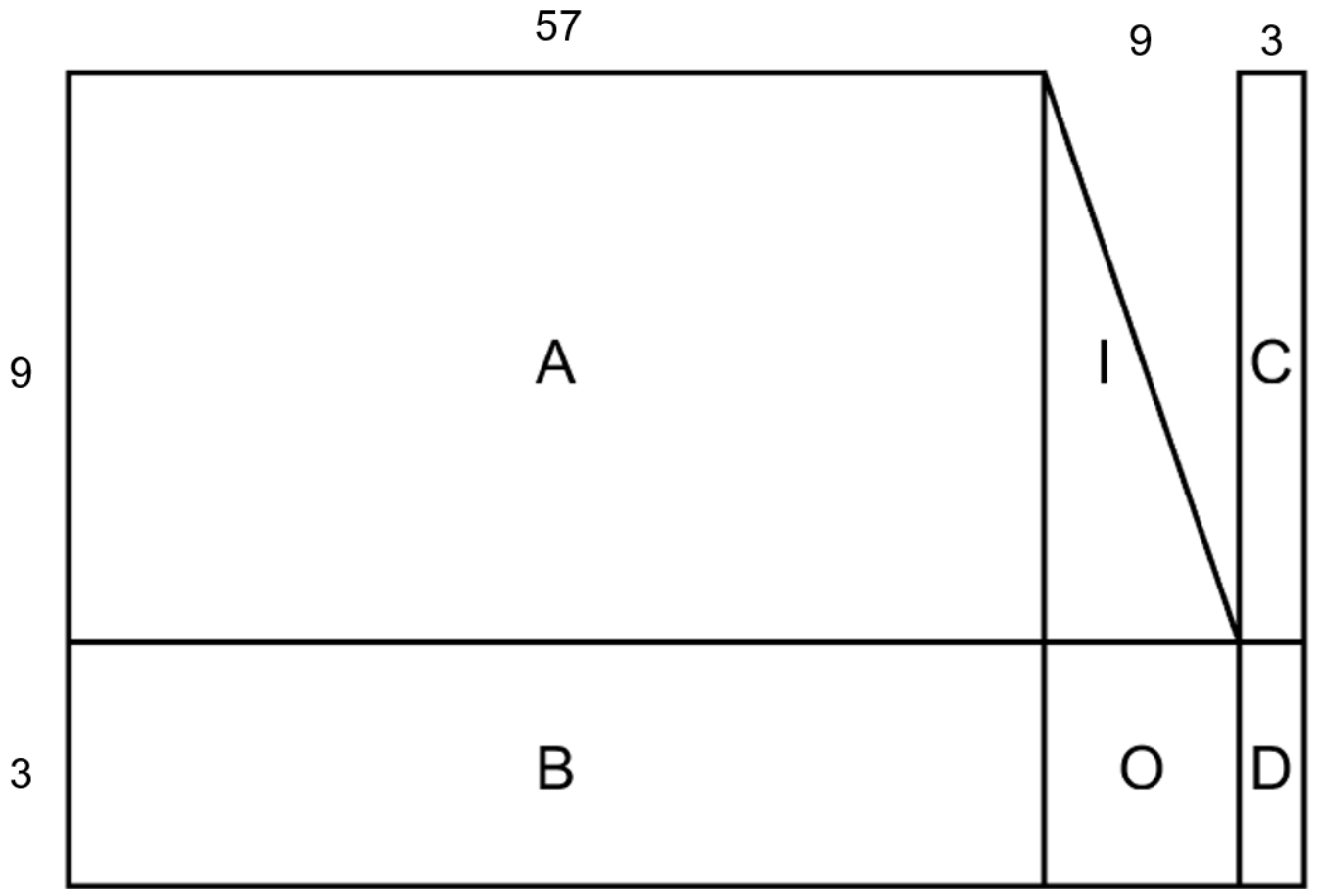
Following degree reduction, H z is partitioned into a structured systematic form: H s y s = [ A | I | C ; B | 0 | D ] , as illustrated in Figure 2. Here, A R 9 × 57 , B R 3 × 57 , I R 9 × 9 , O R 3 × 9 , C R 9 × 3 , and D R 3 × 3 . The matrix I is a 9 × 9 block identity matrix, and O is a 3 × 9 zero polynomial matrix. This partitioning arises directly from the row/column reordering and elimination steps applied to H z and preserves full rank over the polynomial ring.
H s y s = A I C B 0 D
The resulting H sys satisfies two essential encoding requirements: full rank and preservation of the quasi-cyclic structure. These properties are verified analytically and further confirmed by simulation. This structured form enables highly efficient, fully parallelizable encoding—eliminating the need for explicit generator matrix storage while ensuring deterministic latency and minimal logic resource utilization—thereby meeting stringent hardware implementation requirements for 50G-PON systems.
Table 2 presents quantitative statistics on the structural density of the reconstructed systematic parity-check matrix H s y s . Specifically, we measure the total number of nonzero entries within H s y s . As shown in Table 2, the reconstructed base-matrix density is more than 73%. These results confirm that the proposed polynomial-aware reconstruction framework achieves a high-density quasi-cyclic encoding method, enabling low-complexity, fully parallelizable HD-QC-LDPC encoding without compromising error-correction performance.

3.2. The Proposed Efficient Encoding Algorithm

The proposed encoding method involves a specific sequence of steps: Firstly, the transformed check matrix is represented as H s y s . Subsequently, a linear transformation is applied via left multiplication on H s y s .
Furthermore, it is essential to consider the fundamental verification equation H s y s · [ s p ] T = 0 .
A I C B 0 D s p = 0
Upon partitioning the parity bits in codeword c into two segments c = [ s | p a p b ] , expanding Equation (11) gives the block equations for computing the parity vectors p a and p b , as shown in Equation (12), where s R 57 , p a R 9 , p b R 3 .
The proposed encoding method follows a rigorously defined algebraic sequence. First, the systematically transformed parity-check matrix is denoted H s y s . Second, a linear transformation is applied to H s y s .
Crucially, this transformation preserves the fundamental parity-check equation:
H s y s · c T = H s y s · [ s | p ] T = 0 . From this constraint, the parity bits p are uniquely determined by solving H s y s · [ s | p ] T = 0 . The parity vector is partitioned as p = [ p a , p b ] , where dim ( p a ) = 9 z and dim ( p b ) = 3 z . All additions and multiplications in the following equations are performed over R. The block equations are
A s + C p b = p a B s + D p b = 0
Since addition and subtraction are identical over F 2 , and if D is invertible over R, the parity blocks are computed as
p a = ( A + C D 1 B ) s p b = D 1 B s
Under the invertibility condition of D, the parity vector P = [ p a | p b ] becomes a linear function of the information vector s. The generator submatrices are defined as
G a = A + C D 1 B ( mod x 256 1 ) ,
and
G b = D 1 B ( mod x 256 1 ) .
Here, G a R 9 × 57 and G b R 3 × 57 .
The systematic generator matrix is then written as
G = I 57 G a T G b T = I 57 Q ,
where I 57 R 57 × 57 is the block identity matrix and Q = [ G a T G b T ] R 57 × 12 .
The 3 × 3 polynomial matrix D is represented as
D = D 11 D 12 D 13 D 21 D 22 D 23 D 31 D 32 D 33
Thus, D 1 can be computed as the adjugate matrix of D multiplied by det ( D ) 1 over R.
D 1 = inv D 11 inv D 21 inv D 31 inv D 12 inv D 22 inv D 32 inv D 13 inv D 23 inv D 33 · 1 det ( D )
where inv D i j denotes the cofactor term associated with D i j , and the matrix composed of these terms is the adjugate matrix adj ( D ) . The factor 1 det ( D ) denotes the multiplicative inverse of det ( D ) in R. Since the coefficients are in F 2 , subtraction and addition are identical. Therefore, the determinant of D is evaluated as
det ( D ) = D 11 D 22 D 33 + D 12 D 23 D 31 + D 13 D 21 D 32 + D 13 D 22 D 31 + D 12 D 21 D 33 + D 11 D 23 D 32 ,
i n v D 11 = D 22 D 33 D 23 D 32 i n v D 12 = D 21 D 33 D 23 D 31 i n v D 13 = D 21 D 32 D 22 D 31 i n v D 21 = D 12 D 33 D 13 D 32 i n v D 22 = D 11 D 33 D 13 D 31 i n v D 23 = D 11 D 32 D 12 D 31 i n v D 31 = D 12 D 23 D 13 D 22 i n v D 32 = D 11 D 23 D 13 D 21 i n v D 33 = D 11 D 22 D 12 D 21
After computing det ( D ) over F 2 [ x ] , the polynomial is reduced modulo ( x 256 1 ). Its inverse is obtained using the extended Euclidean algorithm. Since gcd ( det ( D ) , x 256 1 ) = 1 , there exist u ( x ) , v ( x ) F 2 [ x ] such that
u ( x ) det ( D ) + v ( x ) ( x 256 1 ) = 1
Therefore,
u ( x ) det ( D ) 1 ( mod x 256 1 )
and hence
1 det ( D ) = det ( D ) 1 u ( x ) ( mod x 256 1 )
The polynomial u ( x ) is finally reduced to a degree less than 256 and used as the scalar multiplier of adj ( D ) in Equation (19).
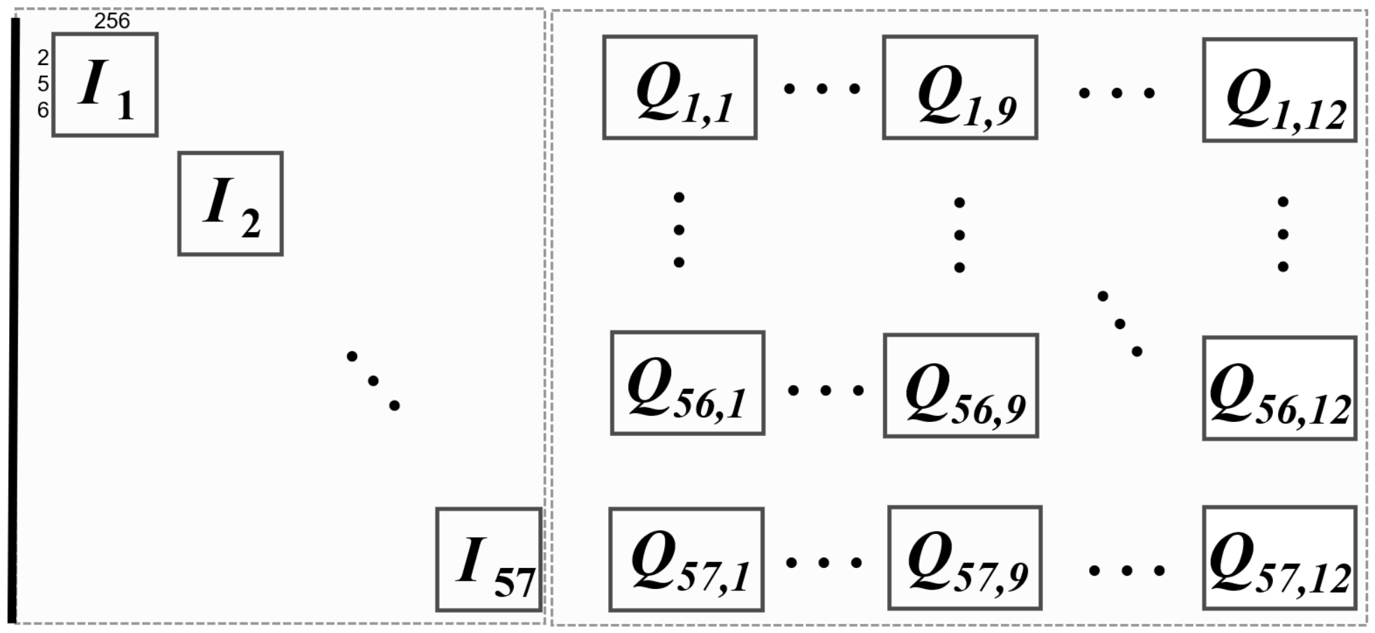
Using D 1 , the generator submatrices G a and G b are computed through polynomial multiplication and modular reduction. These submatrices form Q = [ G a T G b T ] , and the systematic generator matrix is G = [ I 57 Q ] . This representation enables a direct, non-iterative generation of the parity bits. The structure of the final generator matrix is shown in Figure 3.
As shown in Equations (12)–(24), the dominant computational bottleneck in conventional HD-QC-LDPC encoding stems from inverting the full M × M parity submatrix, which requires O ( M 3 ) finite-field operations. In contrast, the proposed algorithm restricts the required inversion to the compact polynomial submatrix D R 3 × 3 , corresponding to a 3 z × 3 z circulant-expanded submatrix. The resulting inverse D 1 is then used to compute the quasi-cyclic generator submatrices G a and G b —thereby constructing the implicit quasi-cyclic generator matrix without an explicit storage of G. This structural transformation enables direct, memory-efficient encoding while ensuring strict compliance with 50G-PON hardware constraints—including deterministic latency and bounded logic depth.
Table 3 reports quantitative statistics on the sparsity profile of the reconstructed generator matrix G. Specifically, we measure the total number of nonzero entries. As shown, G achieves an overall base-matrix density of 97.66%. These results confirm that the proposed polynomial-structured reconstruction delivers provably quasi-cyclic, hardware-adapted encoding for HD-QC-LDPC codes.
In high-throughput 50G-PON operation, the LDPC encoder must generate each codeword—defined as the fundamental unit of encoded data—within a fixed, non-negotiable transmission time slot. No additional cycle budget is allocated for internal computation; thus, end-to-end encoding latency is strictly bounded by the physical layer frame duration. Consequently, encoder design is critically sensitive to computational latency: even sub-cycle delays propagate directly into throughput degradation or packet loss. This paper therefore prioritizes a quasi-cyclic, hardware-friendly structured encoding framework for HD-QC-LDPC codes.
Based on the polynomial-aware reconstruction pipeline detailed in Section 2, Section 3 and Section 4, the complete encoding procedure is formalized in Algorithm 1. The algorithm integrates block-wise Gaussian elimination, circulant-aware row normalization, and modular polynomial arithmetic to transform the original quasi-cyclic parity-check matrix into a systematic form G = [ I | Q ] —enabling direct, parallelizable quasi-cyclic parity-bit generation.
Algorithm 1 Proposed polynomial-domain generator construction algorithm
  1:
Input: Base matrix H base
  2:
Output: Implicit systematic generator structure G = [ I 57 Q ]
  3:
Construct the polynomial matrix H x from H base
  4:
Partition H x into H s and H p
  5:
Rearrange the rows of H x to obtain H y
  6:
Perform polynomial elimination and modular reduction over R
  7:
Decompose the processed matrix H sys into A, I, C, B, 0, and D
  8:
Verify the invertibility of D and compute D 1
  9:
Compute G a = A + C D 1 B
10:
Compute G b = D 1 B
11:
Form Q = [ G a T G b T ] and obtain G = [ I 57 Q ]
In Algorithm 1, all row operations are performed over the quotient ring
R = F 2 [ x ] / ( x z 1 )
with z = 256 for the 50G-PON code. After each row update, every polynomial entry is reduced modulo ( x z 1 ) so that monomials with a degree greater than or equal to z are folded back into the valid circulant range. This guarantees that each nonzero polynomial entry always corresponds to a valid z × z circulant shift block in the lifted QC-LDPC structure. H base denotes the 12 × 69 base matrix, H x denotes its polynomial representation over R, H s and H p denote the information and parity submatrices, respectively, and H sys denotes the transformed systematic parity-check matrix. The matrices G a , G b , and Q are the generator submatrices used for parity generation.

4. High-Throughput High-Density QC-LDPC Encoding

4.1. The Proposed Efficient Encoding Structure

According to Table 3, the generator submatrix Q contains 668 nonzero 256 × 256 circulant sub-blocks. The encoder receives and processes data with a block parallelism of z = 256 bits. Therefore, each block-level operation corresponds to one 256-bit circulant vector operation.
For a target throughput of 50 Gbps at a clock frequency of f clk = 200 MHz, the encoder must output, on average, 50 × 10 9 200 × 10 6 = 250 coded bits per clock cycle. Since one complete codeword contains N = 69 × 256 = 17,664 coded bits, the maximum allowable number of clock cycles per codeword is
N cyc , max = N 250 = 17,664 250 70.66
Thus, the encoding latency must be no more than 70 clock cycles in order to sustain 50 Gbps throughput at 200 MHz.
In the proposed architecture, the 57 information block columns are processed according to a block-level scheduling scheme. Let P g = 12 denote the number of information block columns that can be processed in one scheduling group. The number of scheduling groups required to cover the 57 information block columns is
N g = 57 P g = 57 12 = 5
For each parity block row, one scheduling group is processed in one clock cycle. Therefore, computing one parity block row requires N g = 5 clock cycles.
According to the block partitioning of H sys , the parity vector is divided into p a R 9 and p b R 3 . Thus, the computation of p a contains nine parity block rows, while the computation of p b contains three parity block rows. The latency for computing p a is
N p a = 9 N g = 9 × 5 = 45
Similarly, the latency for computing p b is
N p b = 3 N g = 3 × 5 = 15
Therefore, the total encoding latency is
N cyc = N p a + N p b = ( 9 + 3 ) N g = ( 9 + 3 ) × 5 = 60
This latency model is consistent with Table 4.
It should be noted that the factor 12 represents the block-level hardware parallelism used to form one scheduling group. It is not an additional serial latency factor. Instead, this 12-way parallelism reduces the 57 information block columns to five scheduling groups. The final 60-cycle latency is therefore determined by the number of parity block rows and the number of scheduling groups.
Therefore, the sustained throughput of the proposed encoder is
T = N f clk N cyc = ( 69 × 256 ) × 200 × 10 6 ( 9 + 3 ) × 5 58.9 × 10 9 bps
That is, the proposed encoder achieves a throughput of approximately 58.9 Gbps, which satisfies the 50G-PON throughput requirement.
The overall HD-QC-LDPC encoding process consists of three main operations under modulo-2 arithmetic: addition, dense multiplication, and sparse multiplication. Modulo-2 addition is used in both dense and sparse matrix-vector multiplication and in the recursive computations involving D. In VLSI implementation, each modulo-2 addition can be realized using a single XOR gate. Dense multiplication requires more binary operations than sparse multiplication. Optimizing units for dense multiplication is a key part of encoder architecture design.
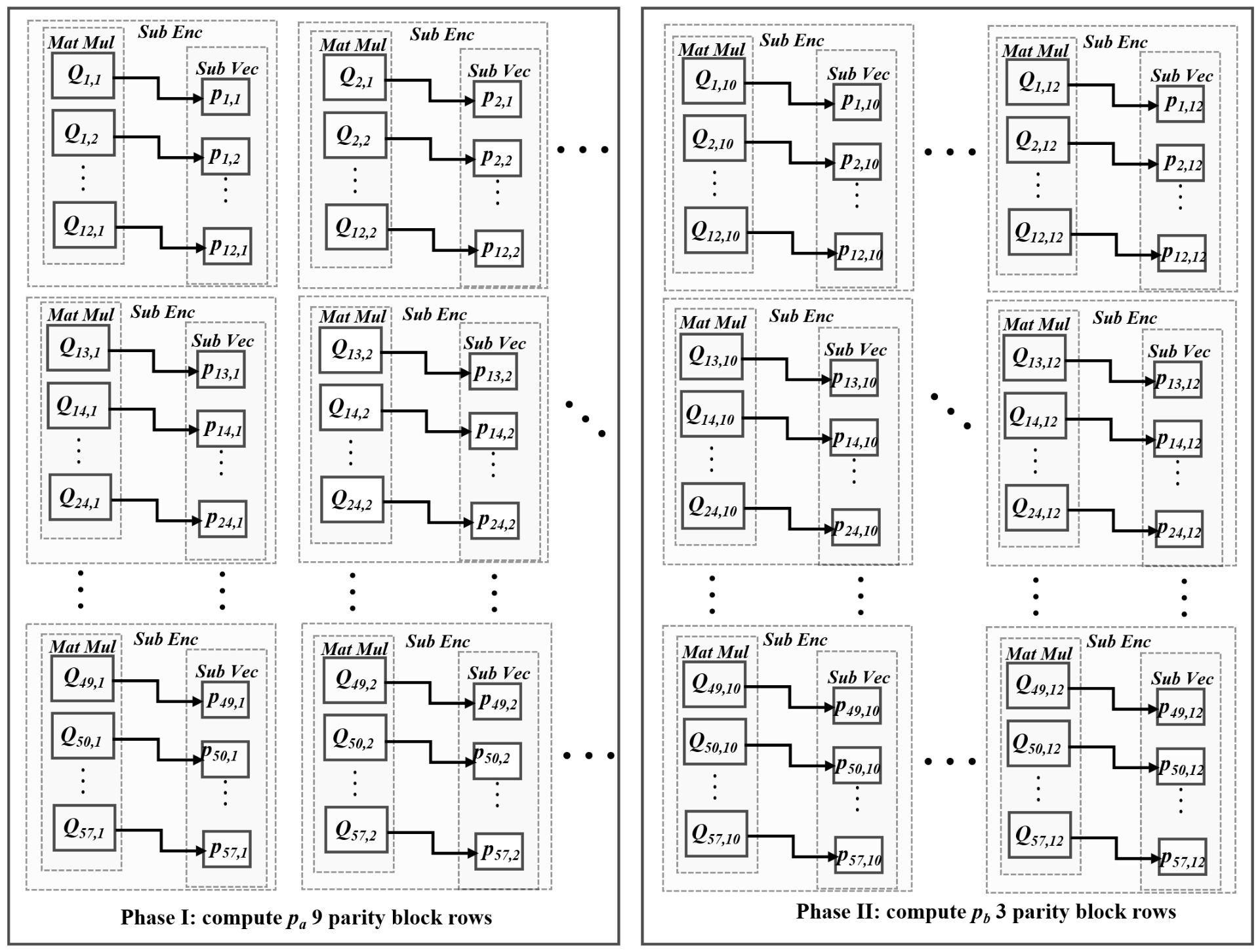
To achieve our objective, we developed a high-speed encoder architecture, which is shown in Figure 4. The generator submatrix Q R 57 × 12 is scheduled row-wise according to the 57 information block columns. The hardware supports P g = 12 parallel block-level circulant operations in one clock cycle. Therefore, the 57 information block columns are divided into N g = 57 / 12 = 5 scheduling groups. For each parity block row, the five groups are processed sequentially, while the 12 entries within each group are processed in parallel. Each horizontal group of 12 submatrices undergoes matrix multiplication to generate the corresponding subblock vectors, which are subsequently combined through an XOR operation.
The proposed HD-QC-LDPC encoding process is performed in two phases. The submodules for computing p a and p b mainly consist of matrix-vector multiplication units and cyclic-shift units. These operations are implemented using hard-wired AND and XOR logic. Each sub-encoding unit performs the cyclic-shift and XOR operations required by the parity-generation equations. The vector p a is computed first using the corresponding rows of Q. The same sub-encoding units are then reused to compute p b in the second phase. The dense multiplication associated with p b starts only after all components of p a have been computed. At the onset of the parity-check bit calculation process, the transmission of information bits commences with corresponding indication signals provided. Upon completion of the check bit calculation, all information bits will have been transmitted. The output control module then transmits the parity bits according to the predefined column order in the next clock cycle. Once transmission is finalized, an end-of-indication signal is issued, and the subsequent data in the current data encoding process are input to the encoder for encoding. Benefiting from the proposed low-complexity polynomial-domain encoding structure, the overall HD-QC-LDPC encoding process requires 60 clock cycles.
The encoder functions with an input data stream parallelism of 256. After receiving all information bits, the p a calculation module generates the first 2304 parity bits. The p b calculation module then generates the remaining 768 parity bits. To minimize resource utilization and improve pipeline execution, the calculation module applies matrix-vector multiplication with cyclic-shift operations using a barrel shifter. In every clock cycle, the product of several submatrices from a column of the base matrix and the incoming 256-bit information bits is determined. Consequently, the result register undergoes a single update. The multiplication operation’s outcome is available concurrently with the reception of information bits, eliminating the requirement for a fixed delay. Because the operation depends mainly on the stored shift values and block schedule, the architecture can be adapted to different code configurations.

4.2. Architecture of the High-Density Unit-Matrix Computation

This section describes the computational architecture of the sub-encoding unit used for high-density matrix-vector multiplication. This unit is used to implement the cyclic-shift-and-XOR operations required by the polynomial-domain parity-generation equations.
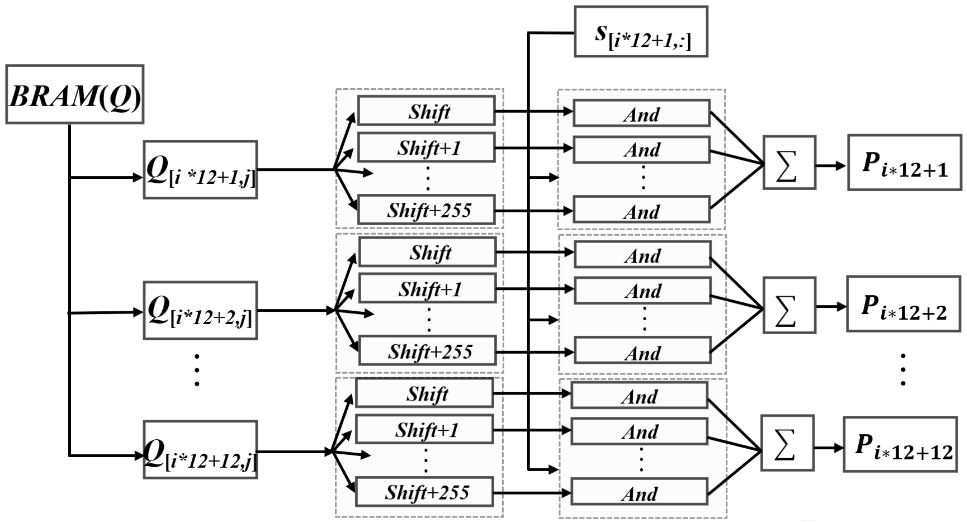
The encoder uses one barrel shifter and one BRAM. The generator submatrix Q is stored in the BRAM and read when required for encoding. Figure 5 shows the architecture of the high-density unit-matrix computation, which performs the multiplication between the input vector and the dense submatrix. A dense multiplication is decomposed into z repeated operations, each consisting of a multiplication, an XOR accumulation, and a cyclic left shift. The cyclic shift network at the end cyclically shifts the outputs of z XOR gates left by one bit as the output of the current level. Each clock cycle contains a cyclic shift operation and an XOR operation. With the barrel shifter and the proposed high-density unit-matrix computation unit, the architecture achieves a better balance between hardware overhead and encoding performance.

5. Implementation Results

The proposed encoding method and hardware architecture target applications requiring scalability, high throughput, and low area complexity. The implemented algorithm exploits significant degrees of freedom within the 50G-PON framework, while subexpression sharing techniques ensure an area-efficient implementation. To evaluate the effectiveness and performance of the proposed encoder, we implemented the design on an FPGA platform and compared the generated codewords with MATLAB 2018 reference results.

5.1. Throughput Analysis

The encoder receives the information sequence and performs encoding. In this case, the frame length is 17,664 and the code rate is 0.83. The information sequence length is 14,592 bits, and the generated codeword length is 17,664 bits. The generated parity bits were compared with the MATLAB reference results, confirming the functional correctness of the encoder. The encoder outputs codewords continuously without idle cycles. The interval between the input-valid signal and the corresponding output-valid signal is 60 clock cycles, which is less than the 256-cycle budget reserved by the downstream module. Table 4 describes the encoding cycles of the proposed architecture. We separately count the number of encoding cycles consumed by p a and p b , as shown in Table 4.
The 60-cycle encoding latency is obtained from the proposed block-level scheduling strategy. The computation of p a involves 9 parity block rows, and each block row is completed in N g = 5 cycles, resulting in 9 × 5 = 45 cycles. Similarly, the computation of p b involves 3 parity block rows, resulting in 3 × 5 = 15 cycles. Therefore, the total encoding latency is N cyc = 45 + 15 = ( 9 + 3 ) × 5 = 60 . This corresponds to the 12 parity block-rows of the 50G-PON parity part, where each parity block-row has a length of z = 256 bits.

5.2. Hardware Resources

As indicated in [23], the throughput performance of the encoder is determined by two key factors: the number of clock cycles required for a single encoding process and its operating clock frequency. To provide a more meaningful comparison, we compare the proposed encoder with both classical FPGA LDPC encoder implementations and recent LDPC/QC-LDPC hardware studies. It should be emphasized that a strictly parameter-identical comparison is difficult because the reported designs target different code families, code lengths, code rates, FPGA devices, and levels of parallelism. Therefore, throughput alone cannot fully reflect the hardware efficiency of an encoder.
The purpose of this comparison is twofold. First, the FPGA results show whether the proposed architecture can achieve the throughput required by 50G-PON. Second, the normalized metrics indicate whether the high throughput is obtained at a reasonable hardware cost. In addition, since recent public FPGA results for 50G-PON HD-QC-LDPC encoders with exactly the same code parameters are still limited, we further provide an algorithm-level comparison with representative dense or near-dense QC-LDPC encoding methods.
It should be noted that the FPGA implementations listed in Table 5 are not strictly parameter-identical designs. They target different code families, code lengths, code rates, FPGA devices, and parallel processing granularities. Therefore, the comparison should not be interpreted as a direct one-to-one ranking based only on absolute throughput. Instead, absolute throughput is used to evaluate whether the encoder satisfies the target system requirement, while resource-normalized metrics are used to indicate hardware efficiency under different implementation constraints.
According to the FPGA resource report, the proposed encoder uses 21,911 flip-flops. The timing report confirms that the design can operate at 200 MHz, thereby satisfying the throughput requirement of 50G-PON. The proposed method reduces the number of dependent computation stages by separating parity generation into two scheduled phases for p a and p b .
The throughput-to-resource overhead ratio (TROR) is first used to evaluate resource-normalized throughput efficiency [32]. It is defined as
TROR = T N LUT + N FF
where T denotes the achieved throughput, N LUT denotes the number of lookup tables, and N FF denotes the number of flip-flops used in the FPGA implementation.
However, TROR alone does not account for differences in codeword length. As the codeword length increases, the hardware resources required for LDPC encoding generally increase because a longer code usually involves a larger generator or parity-check matrix and more block-level operations. Therefore, to reduce the comparison bias caused by different codeword lengths, we further introduce a code-length-normalized TROR, denoted as NTROR:
NTROR = TROR × N N ref
where N denotes the codeword length of the compared design, and N ref = 17,644 denotes the reference codeword length of the proposed 50G-PON encoder. For designs with N < N ref , the factor N / N ref is less than one, which avoids overestimating the resource efficiency of short-codeword encoders when they are compared with the 50G-PON long-codeword encoder. It should be noted that NTROR normalizes the codeword length difference only; differences in code rate, FPGA technology, memory organization, and parallelism level still remain and are discussed qualitatively.
As shown in Table 5, the proposed encoder achieves a TROR of 2.72 and an NTROR of 2.7200. In terms of NTROR, the proposed encoder performs better than [22,23,24] but lower than [31]. The highest NTROR value of 8.0540 is achieved by [31], which is mainly because it uses a much smaller FPGA resource footprint for the shorter Code ( 8176 , 7154 ) .
Although the proposed encoder does not achieve the highest NTROR, it targets the longer 50G-PON Code (17,664,14,592) and achieves the highest absolute throughput of 58.9 Gbps with deterministic 60-cycle latency. Therefore, the proposed design provides a favorable trade-off between normalized resource efficiency and high-throughput long-frame 50G-PON HD-QC-LDPC encoding.
In Table 6, K denotes the information length, M denotes the parity length, z denotes the lifting factor, and N Q denotes the number of nonzero polynomial sub-blocks in the generator submatrix Q. For the proposed 50G-PON HD-QC-LDPC encoder, K = 14,592, M = 3072 , z = 256 , and N Q = 668 . This comparison is necessary because the reported FPGA implementations in the literature usually target different code families, code lengths, code rates, FPGA devices, and degrees of parallelism. Therefore, throughput alone cannot fully reflect the effectiveness of an encoding method for high-density QC-LDPC codes.
Table 6 compares representative LDPC/QC-LDPC encoding methods in terms of their main idea, online encoding complexity, applicability to dense or near-dense QC-LDPC parity-check matrices, and major limitations. The comparison shows that conventional methods either require storing a dense generator matrix, rely on a pre-existing triangular parity structure, or mainly optimize the arithmetic unit without addressing the structural construction problem. In contrast, the proposed method performs a polynomial-domain transformation at the base-matrix level and maps the resulting compact generator structure to cyclic-shift and XOR-based FPGA operations.
As shown in Table 6, the proposed method differs from conventional encoding schemes in both the transformation domain and the target matrix structure. Instead of directly constructing and storing the fully expanded generator matrix, the proposed method preserves the quasi-cyclic structure by operating over R = F 2 [ x ] / ( x z 1 ) . After the offline transformation, the online encoding process only requires cyclic shifts and XOR accumulations associated with the nonzero polynomial sub-blocks of Q. For the 50G-PON HD-QC-LDPC code, N Q = 668 and z = 256 , and the operations are scheduled with block-level parallelism to achieve a deterministic 60-cycle latency. Therefore, the advantage of the proposed method lies not only in the measured throughput but also in its ability to convert a high-density QC-LDPC parity-check matrix into a compact hardware-friendly encoding form.
These results indicate that the proposed encoder architecture is particularly suitable for long-frame, high-throughput HD-QC-LDPC applications such as 50G-PON.

6. Conclusions

This paper presents a polynomial-structured, hardware-oriented encoding algorithm and its implementation for HD-QC-LDPC codes compliant with the 50G-PON standard. By applying modular reduction and circulant-aware Gaussian elimination to the symbolic polynomial parity-check matrix, we derive a systematic quasi-cyclic generator matrix. This architecture achieves deterministic 60-cycle encoding latency independent of frame length, thereby guaranteeing sustained throughput for 50G-PON payloads. The FPGA implementation results demonstrate that the proposed architecture achieves the required 50G-PON throughput with deterministic latency and feasible resource consumption.

Author Contributions

Methodology, Z.L.; Software, X.Z.; Resources, W.G.; Project administration, P.F.; Funding acquisition, L.L. All authors have read and agreed to the published version of the manuscript.

Funding

This paper was supported by the National Natural Science Foundation of China (Grant No. 62271069).

Data Availability Statement

The original contributions presented in this study are included in the article. Further inquiries can be directed to the corresponding author.

Conflicts of Interest

The authors declare no conflicts of interest. The funders had no role in the design of the study; in the collection, analyses, or interpretation of data; in the writing of the manuscript; or in the decision to publish the results.

References

  1. Gallager, R. Low-Density Parity-Check Codes. IRE Trans. Inf. Theory 1962, 8, 21–28. [Google Scholar] [CrossRef]
  2. Mansour, M.M.; Shanbhag, N.R. High-throughput LDPC decoders. IEEE Trans. Very Large Scale Integr. VLSI Syst. 2004, 11, 976–996. [Google Scholar] [CrossRef]
  3. G.9804.3; 50-Gigabit-Capable Passive Optical Networks (50G-PON): Physical Media Dependent (PMD) Layer Specification. International Telecommunication Union-Telecommunication Standardization Sector: Geneva, Switzerland, 2021. Available online: https://www.itu.int/rec/T-REC-G.9804.3 (accessed on 3 May 2026).
  4. Kwon, K.-W.; Kim, K.; Doo, K.; Chung, H.; Lee, J.W. Low-Complexity Architecture for High-Speed 50G-PON LDPC Decoder. IEEE Access 2025, 13, 28751–28765. [Google Scholar] [CrossRef]
  5. Yang, M.; Li, L.; Liu, X.; Djordjevic, I.B. FPGA-based real-time soft-decision LDPC performance verification for 50G-PON. In 2019 Optical Fiber Communications Conference and Exhibition (OFC); IEEE: Piscataway, NJ, USA, 2019. [Google Scholar]
  6. Schmalen, L.; van Wijngaarden, A.J.; Ten Brink, S. Forward Error Correction in Optical Core and Optical Access Networks. Bell Labs Tech. J. 2013, 18, 39–66. [Google Scholar] [CrossRef]
  7. Mahadevan, A.; Lefevre, Y.; Harstead, E.; van Hoof, W.; van Veen, D.; Houtsma, V. Flexible upstream FEC for higher throughput, efficiency, and robustness for 50G PON. In Optical Fiber Communication Conference; Optica Publishing Group: Washington, DC, USA, 2022; p. M3G.5. [Google Scholar]
  8. Mahadevan, A.; van Veen, D.; Kaneda, N.; Duque, A.; van Wijngaarden, A.d.L.; Houtsma, V. 50G PON FEC evaluation with error models for advanced equalization. In 2020 Optical Fiber Communications Conference and Exhibition (OFC); IEEE: Piscataway, NJ, USA, 2020; pp. 1–3. [Google Scholar]
  9. Jiang, Q.; Zhang, P.; Du, S.; Liu, C. Fast encoding of quasi-cyclic low-density parity-check codes in IEEE 802.15.3c. Electron. Lett. 2015, 51, 1713–1715. [Google Scholar]
  10. Tseng, C.F.; Tarng, J.H. Low-complexity and piecewise systematic encoding of non-full-rank qc-ldpc codes. IEEE Commun. Lett. 2015, 19, 897–900. [Google Scholar] [CrossRef]
  11. Chen, W.; Han, C.; Yang, J. Low-complexity encoder for ldpc codes in space applications. Electron. Lett. 2019, 55, 1241–1243. [Google Scholar] [CrossRef]
  12. Zhang, P.; Yu, S.; Liu, C.; Jiang, L. Efficient encoding of qc-ldpc codes with multiple-diagonal parity-check structure. Electron. Lett. 2014, 50, 320–321. [Google Scholar] [CrossRef]
  13. Li, Z.; Chen, L.; Zeng, L.; Lin, S.; Fong, W. Efficient encoding of quasi-cyclic low-density parity-check codes. IEEE Trans. Commun. 2006, 54, 71–81. [Google Scholar] [CrossRef]
  14. Zhang, P.; Liu, C.; Jiang, L. Efficient encoding of qc-ldpc codes based on rotate-left-accumulator circuits. Electron. Lett. 2013, 49, 810–812. [Google Scholar] [CrossRef]
  15. Lin, J.; Wang, Z.; Li, L.; Sha, J.; Gao, M. Efficient shuffle network architecture and application for WIMAX ldpc decoders. IEEE Trans. Circuits Syst. II Express Briefs 2009, 56, 215–219. [Google Scholar] [CrossRef]
  16. Lam, H.M.; Lu, S.; Qiu, H.; Zhang, M.; Jiao, H.; Zhang, S. A high-efficiency segmented reconfigurable cyclic shifter for 5G qc-ldpe decoder. IEEE Trans. Circuits Syst. I Regul. Pap. 2021, 69, 401–414. [Google Scholar] [CrossRef]
  17. Su, J.; Jiang, Z.; Liu, K.; Zeng, X.; Min, H. An efficient low complexity LDPC encoder based on LU factorization with pivoting. In 2005 6th International Conference on ASIC; IEEE: Piscataway, NJ, USA, 2005; Volume 1, pp. 107–110. [Google Scholar]
  18. Mahdi, A.; Paliouras, V. A low complexity-high throughput qc-ldpe encoder. IEEE Trans. Signal Process. 2014, 62, 2696–2708. [Google Scholar] [CrossRef]
  19. Wang, X.; Ge, T.; Li, J.; Su, C.; Hong, F. Efficient multi-rate encoder of qc-ldpc codes based on FPGA for WIMAX standard. Chin. J. Electron. 2017, 26, 250–255. [Google Scholar] [CrossRef]
  20. Richardson, T.J.; Urbanke, R.L. Efficient Encoding of Low-Density Parity-Check Codes. IEEE Trans. Inf. Theory 2001, 47, 638–656. [Google Scholar] [CrossRef]
  21. Mahdi, A.; Kanistras, N.; Paliouras, V. A multirate fully parallel ldpc encoder for the IEEE 802.11n/ac/ax qc-ldpc codes based on reduced complexity xor trees. IEEE Trans. Very Large Scale Integr. VLSI Syst. 2020, 29, 51–64. [Google Scholar] [CrossRef]
  22. Wang, Z.; Hao, X.; Lin, C.; Wu, Q. An efficient hardware LDPC encoder based on partial parallel structure for CCSDS. In 2018 IEEE 18th International Conference on Communication Technology (ICCT); IEEE: Piscataway, NJ, USA, 2018; p. 136. [Google Scholar] [CrossRef]
  23. Ren, W.; Liu, H. The design and implementation of highspeed codec based on FPGA. In 2018 10th International Conference on Communication Software and Networks (ICCSN); IEEE: Piscataway, NJ, USA, 2018; p. 427. [Google Scholar] [CrossRef]
  24. Theodoropoulos, D.; Kranitis, N.; Paschalis, A. An efficient LDPC encoder architecture for space applications. In 2016 IEEE 22nd International Symposium on On-Line Testing and Robust System Design (IOLTS); IEEE: Piscataway, NJ, USA, 2016; p. 149. [Google Scholar] [CrossRef]
  25. Guan, W.; Liang, L. Check-belief propagation decoding of LDPC codes. IEEE Trans. Commun. 2023, 71, 6849–6858. [Google Scholar] [CrossRef]
  26. Liu, Z.; Guan, W.; Yan, Z.; Liang, L. Reliability-List-based Check-Belief Propagation Decoding of LDPC Codes. IEICE Trans. Fundam. Electron. Commun. Comput. Sci. 2024, E108-A, 878–882. [Google Scholar] [CrossRef]
  27. Tanner, R.M.; Sridhara, D.; Sridharan, A.; Fuja, T.E.; Costello, D.J. LDPC block and convolutional codes based on circulant matrices. IEEE Trans. Inf. Theory 2004, 50, 2966–2984. [Google Scholar] [CrossRef]
  28. Milenkovic, O.; Kashyap, N.; Leyba, D. Shortened array codes of large girth. IEEE Trans. Inf. Theory 2006, 52, 3707–3722. [Google Scholar] [CrossRef]
  29. Matsui, H. On generator and parity-check polynomial matrices of generalized quasi-cyclic codes. Finite Fields Their Appl. 2015, 34, 280–304. [Google Scholar] [CrossRef]
  30. Alphiya, A.; Latha, T. An Efficient QC-LDPC channel encoder/decoder architecture with parallel vector-matrix computations for 5G wireless networks on FPGA. Comput. Netw. 2025, 264, 111229. [Google Scholar] [CrossRef]
  31. Liu, J.; Feng, Q. A miniaturized LDPC encoder: Twolayer architecture for CCSDS near-earth standard. IEEE Trans. Circuits Syst. II Exp. Briefs 2021, 68, 2384. [Google Scholar] [CrossRef]
  32. Bao, B.; Guan, W.; Liang, L.; Qiu, X. An efficient GC-LDPC encoder architecture for high-speed NAND flash applications. IEICE Electron. Express 2024, 21, 20230477. [Google Scholar] [CrossRef]
Figure 1. Base matrix H base of the 50G-PON HD-QC-LDPC code.
Electronics 15 02429 g001
Figure 2. The approximate lower triangular form of the parity-check matrix after transformation for HD-QC-LDPC.
Electronics 15 02429 g002
Figure 3. The structure of the final generator matrix.
Electronics 15 02429 g003
Figure 4. Proposed HD-QC-LDPC encoder architecture with 12-way block-level parallelism and five scheduling groups.
Electronics 15 02429 g004
Figure 5. Proposed sub-encoding unit architecture for HD-QC-LDPC encoding.
Electronics 15 02429 g005
Table 1. Density statistics of H base for the 50G-PON HD-QC-LDPC code.
HbaseTotalNumber of Nonzero BlocksAverage Density
MaxMinAverage
Row12232222.9233.21%
Column691233.9933.25%
Table 2. Density of the transformed systematic parity-check matrix H sys .
UnitSizeNumber of Nonzero BlocksDensity
A 9 × 57 37973.88%
B 3 × 57 16697.08%
C 9 × 3 2592.59%
D 3 × 3 9100%
Table 3. Density of the generator matrix G.
UnitSizeNumber of Nonzero BlocksDensity
Q 57 × 12 66897.66%
Table 4. Encoding latency of the proposed architecture.
Total Cyclespa Cyclespb Cycles
604515
Table 5. Hardware comparison with LDPC/QC-LDPC encoder implementations under different code parameters.
WorksRateCode (N, K)FPGAResourcesClockThroughputTRORNTROR
TechnologyLUTsFlip-Flops(MHz)(Gbps)
[22]0.8Code (5120, 4096)Virtex-7101,173141,41120080.330.0957
[23]0.875Code (8176, 7154)Kintex-754,74792,2332972.970.20.0926
[24]0.875Code (8176, 7154)Virtex-5912811562003.123.031.4025
[31]0.875Code (8176, 7154)Virtex-5165810383354.6917.48.054
Proposed0.826Code (17,664, 14,592)Kintex-7194,27121,91120058.92.722.72
Table 6. Compact algorithm-level comparison with representative LDPC/QC-LDPC encoding methods.
MethodMain IdeaComplexity/Hardware ImplicationApplicability and Limitation
Direct G-matrix encodingConstruct and store G, then compute c = s G .About O ( K M ) online operations; large storage for dense G.General but inefficient for long and dense HD-QC-LDPC codes.
Gaussian eliminationConvert H into systematic form over F 2 .About O ( M 3 ) preprocessing on the expanded matrix.General but may destroy the QC structure and hardware regularity.
RU/triangular encodingUse a lower-triangular or near-triangular parity submatrix.Low online complexity if the required structure exists.Efficient for sparse structured LDPC codes, not directly applicable to the dense 50G-PON parity-check matrix.
Partitioned-H encodingPartition H and solve parity bits using smaller submatrices.Depends on the selected submatrix and its density.Requires a compact full-rank parity part; dense intermediate matrices may appear.
Proposed methodUse polynomial-domain transformation over R = F 2 [ x ] / ( x z 1 ) ; compute parity using D 1 , cyclic shifts, and XORs.Online complexity is about O ( N Q z ) , with N Q = 668 , z = 256 ; 60-cycle latency in FPGA.Specifically designed for 50G-PON HD-QC-LDPC; preserves QC structure and avoids full dense G storage.
Disclaimer/Publisher’s Note: The statements, opinions and data contained in all publications are solely those of the individual author(s) and contributor(s) and not of MDPI and/or the editor(s). MDPI and/or the editor(s) disclaim responsibility for any injury to people or property resulting from any ideas, methods, instructions or products referred to in the content.