Article

Seamless Switching Strategy for Grid-Following and Grid-Forming Control of Grid-Connected Energy Storage Systems


School of Automation, Chongqing University, Chongqing 401331, China
*
Author to whom correspondence should be addressed.
Electronics 2026, 15(11), 2315; https://doi.org/10.3390/electronics15112315
Submission received: 27 April 2026 / Revised: 20 May 2026 / Accepted: 25 May 2026 / Published: 27 May 2026

Abstract

To supply indispensable transient inertia and damping support for power systems, particularly weak grid scenarios, grid-forming (GFM) generation exhibits superior performance compared with traditional grid-following (GFL) interfaces. Nevertheless, conventional GFL/GFM mode transition schemes suffer from abrupt switching behaviors or slow dynamic responses, which easily induce relay maloperation and even large-scale system instability. To tackle these drawbacks, this paper presents a seamless operating mode switching strategy for inverter-based power generation units. By coordinately optimizing the output states of phase-locked loop (PLL) and multi-loop current controllers, severe transient voltage and current surges during mode transition are effectively suppressed. A 2 MW grid-connected energy storage system is developed to validate the proposed control algorithm. The results demonstrate the feasibility and effectiveness of the proposed seamless switching strategy under grid-connected energy storage system scenarios.

1. Introduction

Driven by escalating environmental pressures and the imperative for decarbonization, the global energy landscape is undergoing a paradigm shift from fossil fuels to renewable sources such as wind and solar [1]. This transition has been accelerated by significant technological maturation and cost reductions in power electronics, leading to an unprecedented penetration of inverter-based resources (IBRs) into modern power grids [2]. While this evolution promises a sustainable energy future, the sheer scale of integration is fundamentally reshaping grid dynamics, transforming traditional power systems into complex, power-electronics-dominated networks and introducing new challenges to operational stability that were negligible in conventional synchronous-dominated systems [3,4].
Unlike conventional synchronous generators with substantial rotating mass providing inherent inertia, IBRs exhibit low inertia and fast-response characteristics due to their control-dependent nature [5,6]. This shift results in diminished system damping and heightened sensitivity to disturbances, rendering the grid increasingly vulnerable to transient instability and voltage/frequency fluctuations [7]. Furthermore, as renewable capacity expands, power grids are trending towards weak grid conditions characterized by low short-circuit ratios (SCR) [8]. Under these conditions, the dynamic interactions between the converter control systems and the grid impedance become highly complex and strongly coupled. The multi-time-scale interactions, nonlinearities, and control intricacies of IBRs under weak grid conditions obscure the mechanisms of instability, rendering conventional control paradigms inadequate [9].
Current grid-connected renewable energy systems are predominantly categorized into Grid-Following (GFL) and Grid-Forming (GFM) architectures based on their synchronization mechanisms. While GFL inverters, which rely on Phase-Locked Loops (PLLs) to synchronize with the grid voltage, constitute most of the installed capacity due to their mature technology and lower cost, they function merely as current sources [10]. This dependence renders them critically vulnerable during grid faults or under weak grid conditions; specifically, GFL units lack the intrinsic voltage source behavior required to provide inertial support or stabilize frequency and voltage during emergencies [11]. Consequently, although GFL systems dominate the current landscape, their inability to actively support the grid during disturbances poses a significant risk to the overall resilience of modern power systems [12].
In contrast, GFM technology emulates synchronous generator behavior, offering independent voltage and frequency regulation indispensable for islanded operations and weak grids [13,14]. However, its higher complexity limits widespread adoption compared to GFL. While both topologies are applicable to renewable generation, the unique operational flexibility required by energy storage systems—specifically the need for rapid bidirectional power adjustment and instantaneous grid support during contingencies—necessitates a hybrid approach. To bridge this gap, this paper develops a novel seamless switching logic specifically tailored for grid-connected energy storage systems, enabling the system to maintain grid-following operation under normal conditions while instantly switching to grid-forming support during contingencies.
Although various seamless transition schemes have been reported, a critical review reveals that most contemporary approaches essentially rely on hard-switching mechanisms [15]. This inherent rigidity often results in a sluggish dynamic response, where the abrupt alteration of control structures introduces significant transient impulses [16]. Consequently, the lack of smooth trajectory tracking during mode transfer frequently excites system oscillations, undermining the stability and reliability of the power electronics interface. This prevalent limitation underscores the necessity for a more refined control architecture capable of mitigating transient shocks while ensuring rapid mode adaptability.
Despite growing research efforts addressing the seamless transition between GFL and GFM control, existing methodologies still exhibit significant limitations in computational efficiency and dynamic performance. For instance, while Gao et al. proposed a smooth switching strategy, it overlooks the disturbance of grid transients on Phase-Locked Loop (PLL) tracking dynamics, risking synchronization instability during startup [17]. Similarly, Zhou et al. introduced a dual-loop cooperative scheme using S-shaped weighting functions; however, its requirement for two parallel control paths leads to excessive computational overhead and hardware costs, hindering millisecond-level bidirectional switching [18]. Furthermore, Sadeque et al. presented a semi-parallel transition method, yet it is restricted to unidirectional GFL-to-GFM switching and lacks active rate-limiting constraints, resulting in limited transient impulse suppression [19]. Collectively, these studies reveal a critical trade-off: strategies ensuring smooth transitions often suffer from structural redundancy and high complexity, failing to achieve a balance between low-cost implementation and robust performance under diverse grid disturbances [20]. These prevailing trade-offs underscore the necessity for a more integrated approach. Table 1 provides a comparative overview, highlighting how the proposed dual-soft switching mechanism addresses these specific limitations.
The principal contributions of this work are summarized as follows:
  • A Unified Dual-Soft Switching Mechanism: We propose a novel seamless transition strategy that fundamentally resolves the trade-off between structural complexity and transient performance. By integrating PLL input blocking with bidirectional rate limiting, the architecture eliminates the abrupt reference steps that cause system oscillations. Crucially, a rigorous parameter sensitivity analysis is provided, deriving theoretical bounds to ensure both surge suppression and PLL synchronization stability.
  • Hardware-in-the-Loop (HIL) Validation: Moving beyond pure software simulation, this work establishes a Typhoon HIL602-based real-time experimental platform (Typhoon HIL, Inc., Somerville, MA, USA) with a 2 MW grid-connected energy storage system. Comparative results demonstrate that the proposed scheme outperforms conventional methods by suppressing active power overshoot by 51.8% and achieving zero distorted cycles across a wide SCR range (1.5 to 4).
  • Engineering-Oriented Implementation: The study provides a practical pathway for renewable energy integration. Unlike theoretical models, the proposed strategy considers real-world constraints such as filter resistance and controller delays, bridging the gap between academic innovation and industrial deployment.

2. Unified Architecture Based on GFL and GFM Control

2.1. Grid-Connected Converter Topology with Energy Storage Constraints

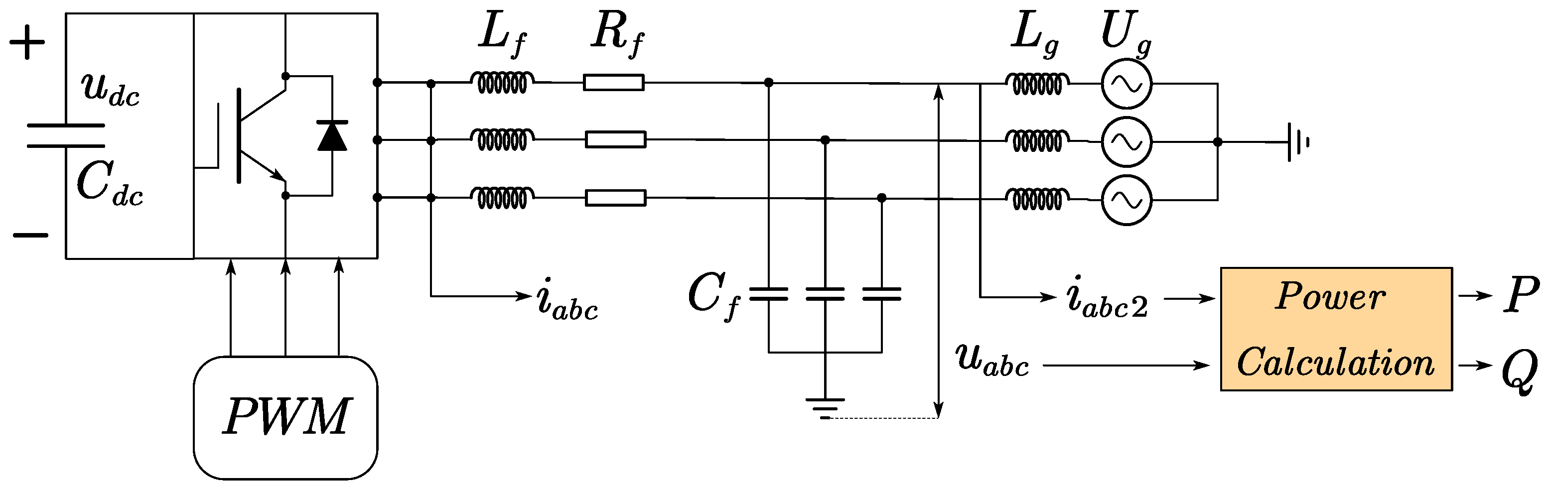
To address current quality and voltage support demands in renewable energy systems, this study investigates the dynamic interactions between GFL and GFM control using a three-phase LCL-type grid-connected converter, as shown in Figure 1 [21]. The topology consists of a DC-side equivalent power source u d c , a DC-link capacitor C d c , converter bridge arms, an LCL output filter, and an AC grid equivalent voltage source U g . Specifically, the LCL filter comprises the converter-side inductor L f , the filter capacitor C f , and the grid-side inductor L g .
As the core component for energy storage and buffering, the DC-link capacitor C d c not only electrically decouples the renewable energy source (e.g., wind turbine) from the grid side but also effectively mitigates DC-side power fluctuations and stabilizes the bus voltage [22,23]. Given the stability risks posed by the inherent resonant characteristics of the LCL filter, a parasitic resistor R f on the converter-side inductor is introduced into the model to implement passive damping control [24,25].
To accurately emulate the physical constraints of a grid-connected energy storage system while maintaining focus on the control strategy, the DC-side model incorporates a simplified representation of the battery dynamics and operational limits. Instead of an ideal voltage source, the DC-link voltage is regulated by a voltage regulation loop to reflect the charging and discharging characteristics of energy storage [26]. The State-of-Charge (SOC) is calculated in real-time based on the power balance: S O C ( t ) = S O C 0 1 E r a t e d P d c ( t ) d t , where P d c ( t ) is the DC-side power and E r a t e d is the total capacity, maintained within the operational range of 10–90%. Furthermore, a hard current limit of 1.2 p.u. is imposed on the battery side to emulate the over-current protection mechanism of practical Battery Management Systems (BMS) [27], ensuring the feasibility of the proposed switching strategy under physical constraints.
To achieve control over key electrical quantities in the power system for the main power circuit, it is first necessary to acquire three types of signals in the three-phase stationary reference frame across the LCL filter: the converter-side inductor currents i a b c (transformed into i d , i q ), the filtered voltage signals u a b c (transformed into u d , u q ), and the filtered grid-side current signals i a b c 2 (transformed into i o d , i o q ).
The power calculation principle is based on the decoupled electrical quantities obtained via coordinate transformation, enabling precise characterization of active and reactive power by quantifying the interaction between voltage and current components. Since instantaneous power calculation requires extracting the fundamental components to reflect real energy exchange, the processed voltage signals u a b c and current signals i a b c 2 from the LCL filter are used. The transformed values u d , u q , i o d , i o q are then employed to compute the active power P and reactive power Q . This approach prevents deviations caused by distorted signals and ensures that and represent only the fundamental active and reactive components. The core calculation formulas are presented below:
P = 3 2 u d i o d + u q i o q Q = 3 2 u q i o d u d i o q
In summary, this subsection establishes a detailed mathematical model for the three-phase LCL-type grid-connected converter, tailored for renewable energy and energy storage units. The modeling work fully accounts for the system’s high-frequency characteristics and damping constraints, laying a solid hardware and theoretical foundation for the unified design of grid-following and grid-forming control strategies, as well as the seamless transition mechanism to be developed in subsequent sections.

2.2. GFL Control Architecture

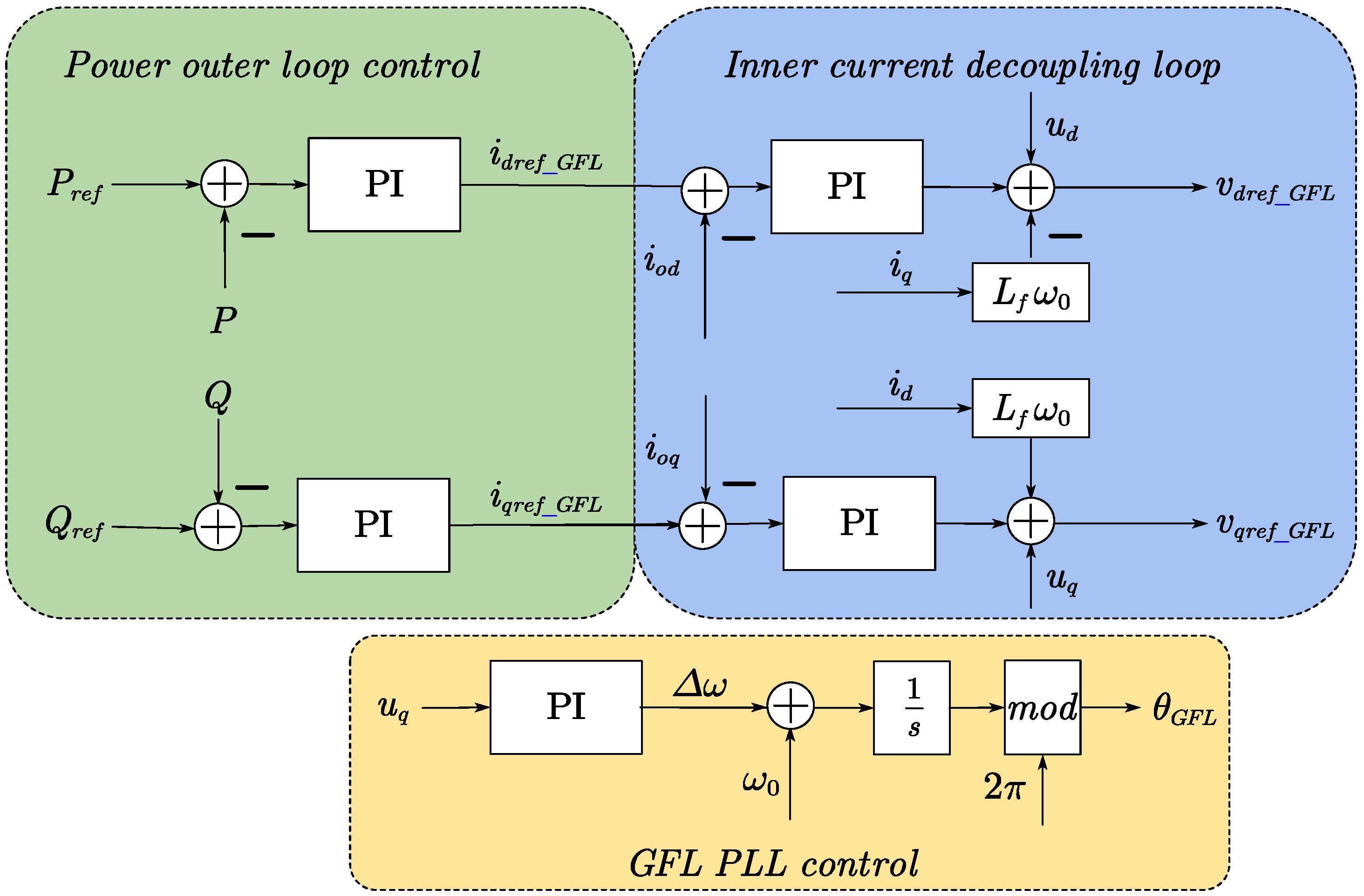
Based on the mathematical model of the main power circuit topology, this section elaborates on the fundamental principles of grid-following control. The grid-following control architecture is illustrated in Figure 2. Grid-following control is essentially a current-source control strategy based on a Phase-Locked Loop (PLL). Its core logic lies in utilizing the PLL to track the phase and frequency of the grid voltage in real time, which serves as the reference for the internal control coordinate system [28]. In this mode, the converter behaves as a controlled current source, precisely regulating the active and reactive power injected into the grid by adjusting the amplitude and phase of the output current.
When the system operates in Grid-Following (GFL) mode, the generation of its phase angle θ G F L is entirely governed by the Phase-Locked Loop (PLL). The system samples the filtered three-phase grid voltages u a b c and extracts their q-axis component u q , comparing it with the reference value u q * = 0 . The error signal is fed into a PI controller for closed-loop regulation. The output of the PLL’s PI controller generates the frequency deviation signal ω , which is then added to the nominal angular frequency ω 0 and integrated to produce the phase angle that is strictly synchronized with the grid. The core mechanism of the PLL leverages the integral action of the PI controller to eliminate steady-state error. Through negative feedback, it continuously adjusts the frequency, forcing u q to converge to zero, thereby achieving real-time, zero-error tracking of the grid voltage phase. The generated phase angle is subjected to a modulo operation to limit its range from 0   t o   2 π , yielding θ G F L and ensuring the periodicity of the phase angle.
θ G F L = u q K p , P L L + K i , P L L s + ω 0 s
where K p , P L L and K i , P L L are proportional and integral coefficients of PLL, respectively. When the system operates in Grid-Following (GFL) mode, the outer loop employs closed-loop power control as its core to achieve tracking and regulation of active and reactive power. The system acquires active power reference P r e f and the actual output active power P to obtain deviation, as well as the reactive power reference Q r e f and the actual output reactive power Q to obtain deviation. These two sets of error signals are fed into independent active and reactive power PI controllers, respectively. The outputs of these PI controllers directly generate the d-axis and q-axis current references and in the synchronous rotating reference frame, providing precise reference benchmarks i d r e f _ G F L , i q r e f _ G F L for the subsequent current inner loop decoupling.
i d r e f _ G F L = ( P P r e f ) K p , P + K i , P s i q r e f _ G F L = ( Q Q r e f ) K p , P + K i , P s
where K p , P and K i , P are proportional and integral coefficients of PI controller in power outer loop respectively. It is worth noting that during simulations focusing on current-loop dynamics or transient switching scenarios, the power outer loop is often omitted, and the current references are set as constant values directly. This is because when the system operates in steady state with fixed reference power, the integral action of the PI controllers drives the deviations P and Q to zero, causing the output current references to remain constant. In the synchronous rotating reference frame, once the PLL is fully locked to the grid voltage U g , the grid voltage vector aligns perfectly with the d-axis. Consequently, the q-axis component of the grid voltage becomes u q = 0 , and the d-axis component becomes u d = U g . Based on this premise, specific formulas for calculating the current references can be derived by transforming the instantaneous active and reactive power calculation formulas, as follows:
i d r e f _ G F L 2 3 P r e f U g i q r e f _ G F L 2 3 Q r e f U g
The outer-loop power compensation control calculates the current component references i d r e f _ G F L and i q r e f _ G F L , enabling the inner loop to perform precise regulation and decoupling actions around these references. The inner-loop current decoupling control constitutes the core mechanism for achieving accurate current regulation and decoupling in power electronic systems [29]. It is constructed based on the dq-axis decoupling network and separates the d-axis and q-axis current control loops through the synergistic effect of PI controllers and cross-coupling term compensation. The core formula for this control stage is presented as follows:
v d r e f _ G F L = ( i d r e f _ G F L i o d ) K p , I + K i , I s i q L f ω 0 + u d v q r e f _ G F L = ( i q r e f _ G F L i o q ) K p , I + K i , I s + i d L f ω 0 + u q
where K p , I and K i , I are proportional and integral coefficients of PI controller in inner-loop current decoupling control respectively. The final outputs, v d r e f _ G F L and v q r e f _ G F L , are the reference voltage components prior to the coordinate transformation feeding into the Pulse Width Modulation (PWM) stage. They provide precise voltage commands for the subsequent PWM module, thereby guaranteeing the current control dynamic performance and stability of the system across multiple operating modes [30,31].
The PWM stage acts as the critical interface that converts electrical signals into gate drive pulses for the inverter [32]. This process relies on two key inputs: the dq-axis reference voltages v d r e f _ G F L and v q r e f _ G F L generated by the inner-loop current decoupling control, and the grid phase angle θ G F L provided by the Phase-Locked Loop (PLL). Based on these inputs, the PWM module first transforms the voltage quantities from the synchronous rotating (dq) reference frame to the stationary (abc) reference frame, yielding the phase-specific voltage components corresponding to the inverter legs. Subsequently, the PWM module generates pulse sequences with precise duty cycles and frequencies based on the amplitude and phase characteristics of these three-phase voltages. These pulses are then sent to the inverter power switches, regulating the inverter output voltage by strictly controlling the turn-on and turn-off instants of the switching devices.
This GFL mode is widely adopted in grid-tied wind power converters and grid-side energy storage systems due to its straightforward control structure and high current tracking accuracy. However, its dependence on the grid voltage phase and its inability to autonomously establish voltage magnitude limit its operational capability in weak grids or islanded environments.

2.3. GFM Control Architecture

Based on the mathematical model of the main power circuit topology, this section systematically elaborates on the fundamental principles of grid-forming (GFM) control. The grid-forming control architecture is illustrated in Figure 3. Grid-forming control is essentially a voltage-source control strategy characterized by droop characteristics. Its core logic lies in emulating the physical properties of primary frequency and voltage regulation in synchronous generators. Unlike grid-following mode, it does not require a Phase-Locked Loop (PLL) to track the grid phase. Instead, it autonomously establishes and maintains the amplitude and frequency of the output voltage by utilizing the droop control laws of active power–frequency P f and reactive power–voltage Q V . In this mode, the converter exhibits the characteristics of a controlled voltage source, directly regulating the active and reactive power injected into the grid by adjusting the amplitude and phase of its output voltage [33].
When the system operates in Grid-Forming (GFM) mode, the generation of its phase angle θ G F M is entirely governed by the active power–frequency P f droop control, eliminating the need to rely on a Phase-Locked Loop (PLL) to track the grid phase. The system acquires the actual output active power P of the converter and compares it with the active power reference P r e f to obtain the active power deviation Δ P = P r e f P . This error signal is fed into the droop control block, where the frequency deviation is calculated Δ ω = K p Δ P using the droop coefficient K p . Subsequently, Δ ω is added to the nominal angular frequency ω 0 and integrated to autonomously generate the phase angle θ that matches the system’s power balance. The core mechanism of droop control utilizes a power synchronization mechanism [34]. By emulating the primary frequency regulation characteristics of synchronous generators, it autonomously adjusts the output frequency and phase based on the system’s active power supply-demand relationship. This enables the system to provide active support to the grid frequency and achieve non-deviation synchronization. The generated phase angle is subjected to a modulo operation to limit its range from 0 to 2 π , yielding θ G F M . This ensures the periodicity of the phase angle and provides the reference for the synchronous rotating coordinate system required for the subsequent inner-loop voltage control.
θ G F M = K p P r e f P + ω 0 s
The generation of the d-axis reference voltage for the system’s voltage outer loop is implemented based on the reactive power–voltage Q V droop control. First, the actual output reactive power of the converter Q is sampled and compared with the given reactive power reference Q r e f to obtain the reactive power deviation Δ Q = Q r e f Q . This deviation signal is fed into the droop control block, where the voltage deviation is calculated Δ U = K q Δ Q using the droop coefficient K q . Subsequently, Δ U is superimposed with the no-load voltage U 0 representing the system’s rated operating condition, together forming the d-axis reference voltage for the voltage outer loop. Setting the q-axis reference voltage to zero is intended to achieve decoupled control of active and reactive power in the synchronous rotating (dq) reference frame. This assigns the d-axis specifically to regulate active power and voltage magnitude, thereby simplifying the control algorithm and enabling independent, precise adjustment of the system’s power [35].
The system’s voltage outer loop regulates the error between the voltage reference and feedback via PI controllers, incorporating cross-coupling compensation and current feedback to generate the current references i d r e f _ G F M and i q r e f _ G F M for the inner current loop, thereby providing precise reference benchmarks. Mathematically, this process is implemented through the following equations:
i d r e f _ G F M = ( K q ( Q r e f Q ) u d ) K p , U + K i , U s u q C f ω 0 + i d i q r e f _ G F M = ( 0 u q ) K p , U + K i , U s + u d C f ω 0 + i q
where K p , U and K i , U are proportional and integral coefficients of PI controller in voltage outer loop respectively. In the equation, i d r e f _ G F M and i q r e f _ G F M are the current component references for the inner current loop control; u d and u q are the actual feedback voltages on the d- and q-axes. The voltage outer-loop PI controller eliminates steady-state errors in voltage control through proportional-integral operations on the error signals. Since the capacitor voltage exhibits cross-coupling dynamic characteristics characterized by C f ω 0 , the cross-coupling compensation terms in the formulas are designed to counteract the voltage coupling interference between the d- and q-axes, thereby preserving the decoupling property of the control. The currents i d and i q represent the actual current components fed back from the inner loop; their inclusion enhances the system’s tracking response to current commands and its disturbance rejection capability. Ultimately, the generated i d r e f _ G F M and i q r e f _ G F M serve as the reference inputs for the inner-loop decoupling control, enabling precise current regulation and decoupling actions centered around the reference values. This ensures dynamic performance and stable operation of the entire power electronic system under diverse operating conditions.
The outer-loop voltage control calculates the current component references i d r e f _ G F M and i d r e f _ G F M , enabling the inner current loop to perform precise regulation and decoupling actions around these references. The principles of the inner-loop current decoupling control and the subsequent PWM stage are consistent with those described in Section 2.2 for the grid-following control architecture: based on the generated dq-axis reference voltages v d r e f _ G F M and v q r e f _ G F M , combined with the grid phase angle θ G F M autonomously established by the droop control, an inverse transformation is performed to obtain the voltage components in the stationary abc reference frame, which correspond directly to the inverter’s three-phase legs. These components are then fed into the PWM module to regulate the inverter’s output voltage.
This grid-forming (GFM) mode exhibits the capability to autonomously establish voltage magnitude and frequency by emulating the primary frequency and voltage regulation characteristics of synchronous generators, significantly enhancing weak-grid adaptability and islanded operation stability. However, its control structure is relatively complex, imposing higher requirements for parameter tuning and dynamic coordination. Particularly during grid-connected or islanded mode transitions, it is prone to inducing power oscillations, which also poses greater challenges to the stability design concerning multi-time-scale dynamic interactions [36].

2.4. Establishment of the Unified Control Framework

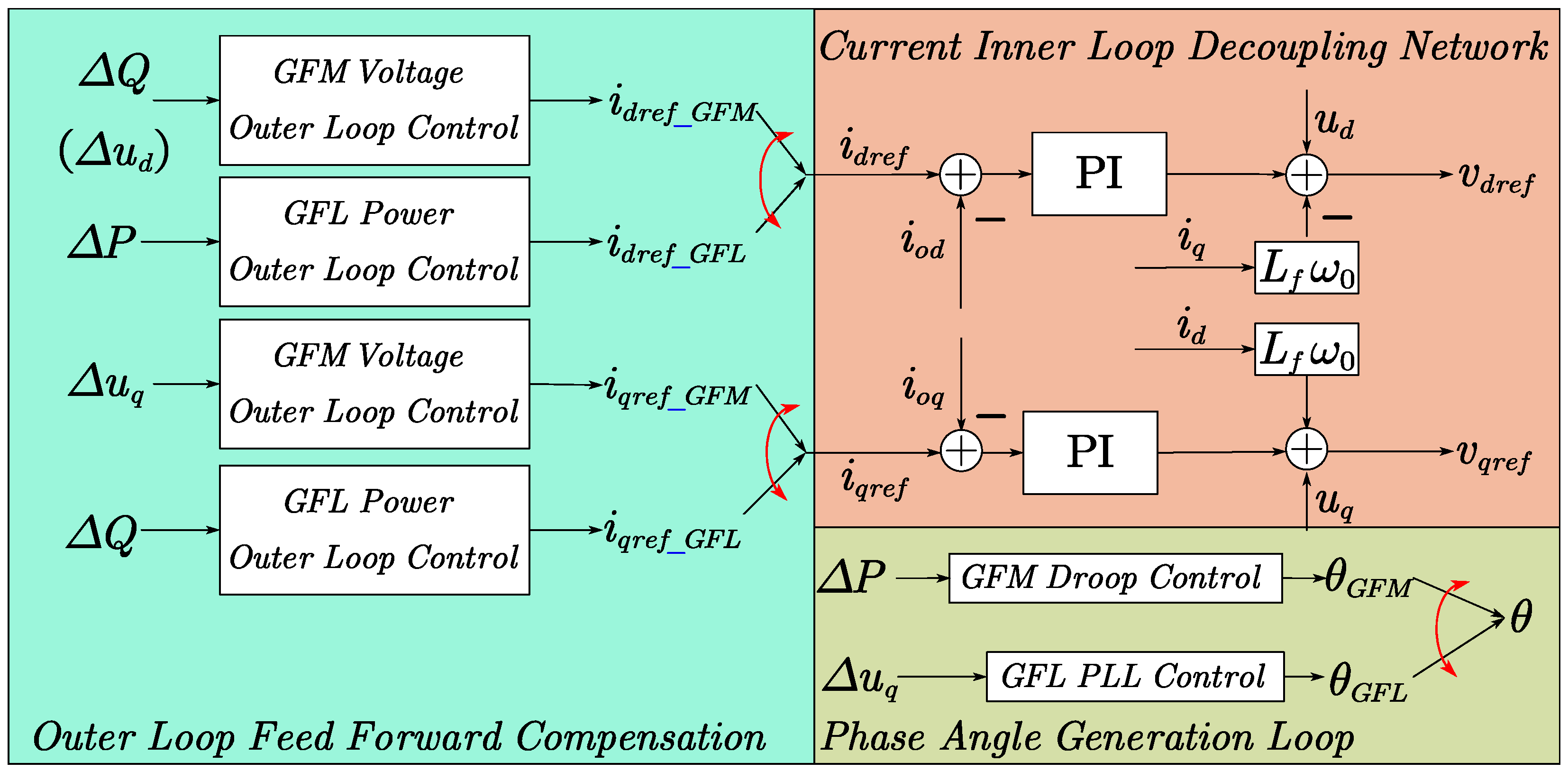
As summarized from the preceding analysis, the unified control architecture is illustrated in Figure 4. It can be observed that for both grid-following and grid-forming controls, the inner-loop current decoupling control and PWM stages share a common structure, with the core distinctions lying solely in the outer-loop control logic and the reference phase generation mechanism.
Based on the dissection of these two modes, although they manifest as current-source and voltage-source behaviors respectively, their hardware architectures and signal processing chains are highly isomorphic. The essential difference resides only in the outer loop and phase generation units: the grid-forming type autonomously constructs the voltage feed-forward and phase via Q-V and P-f droop control, whereas the grid-following type relies on a PLL to track the grid and employs power feed-forward. Therefore, a unified architecture sharing the current inner loop and PWM offers significant engineering value. This design not only avoids redundant development and reduces hardware/software costs and maintenance complexity but also ensures low harmonics and high precision in the output current under any mode due to the fast dynamic response of the inner current loop. It effectively isolates the impact of mode transitions on power devices, providing the physical foundation for achieving smooth, seamless switching.

3. Seamless Switching Logic for GFL and GFM Control

3.1. Mode Switch Signal CT

We define the Mode Switch Signal CT as the core instruction carrier for mode switching and control within the system. Its logic level contains explicit state definitions: when CT = 0, the system operates in grid-following (GFL) mode; when CT = 1, it switches to grid-forming (GFM) mode. In terms of signal edge characteristics, the falling edge (the instant the signal transitions from high to low) corresponds to the transition from GFM to GFL, while the rising edge (the instant the signal transitions from low to high) corresponds to the transition from GFL to GFM.
In practical engineering applications, the initial value of CT is typically defaulted to 1. This is because, during the system startup phase, it is necessary to prioritize the GFM mode to complete initialization tasks such as power support and voltage buildup on the generation side, thereby establishing a solid foundation for subsequent grid-connected or islanded operation. As a global dispatch signal, CT directly determines the topology selection and parameter tuning of the phase angle generation unit and the feed-forward control loop. Consequently, it provides the core basis for designing the specific control strategies under different modes, as detailed in Section 3.2 and Section 3.3.
While prior studies—such as [37,38,39,40]—have extensively investigated the decision-making logic for mode switching, focusing on criteria like short-circuit ratio (SCR) thresholds to determine whether a transition should occur, this work adopts a complementary perspective. Instead of designing new triggering mechanisms, this study assumes that a mode switch command has already been issued by an upper-level energy management system or grid code requirement. Consequently, the research focuses exclusively on the execution layer: namely, how to implement the switching instruction carried by the CT signal seamlessly and stably, regardless of the specific grid condition that initiated the request. This delineation allows the control strategy to be decoupled from specific triggering policies, enhancing its generality and interoperability.

3.2. Seamless Switching of the Phase Angle Generation Unit

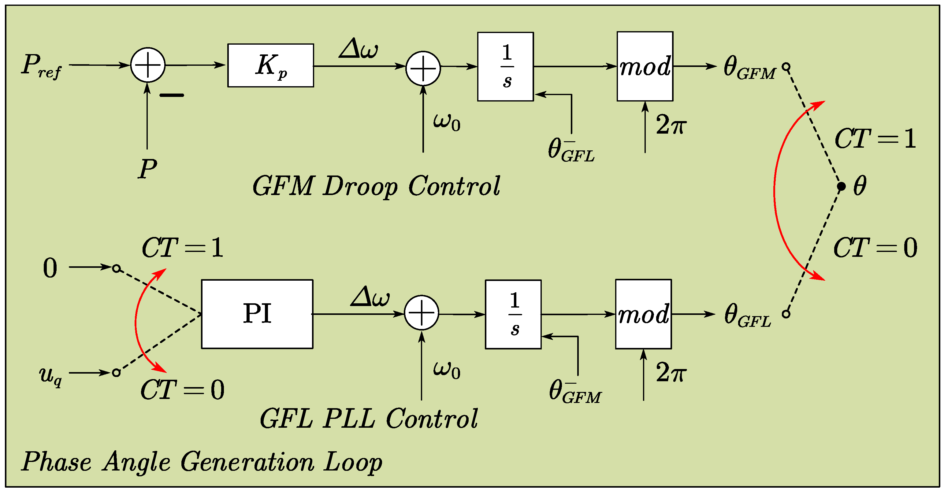
As shown in Figure 5, the switching of the system operation mode is uniformly triggered by the Mode Switch Signal CT. The core of the transition process lies in the smooth handover of the phase generation unit and the dynamic inheritance of the integrator initial values. When toggles, the system not only switches the control path but also ensures phase continuity through a specific integral reset mechanism.
During the transition from GFL to GFM, the system activates the droop control path to generate the phase angle θ G F M . To prevent integrator saturation and ensure a smooth transition, an external trigger reset mechanism is applied to the integrator in the GFM path. Let θ G F L denote the phase value in GFL mode at the instant immediately before switching; the initial value of the GFM integrator is forcibly reset to this value:
θ G F M 0 + = θ G F L
Subsequently, the phase generation follows the droop dynamic equation:
θ G F M t = ω 0 + K p P r e f P d t | θ G F M 0 +
Conversely, during the transition from GFM to GFL, the system activates the PLL path. Similarly, the initial value of the integrator in the GFL path is reset to the phase value of the GFM mode θ G F M immediately before switching, thereby guaranteeing a seamless connection of the phase trajectory:
θ G F L 0 + = θ G F M
It is worth noting that in GFM mode, the input signal to the Phase-Locked Loop (PLL) must be strictly forced to zero (i.e., setting u q = 0 ). Analyzing the control mechanism, retaining the grid voltage u q as the PLL input would result in competition between two phase sources: the PLL attempts to lock onto the grid phase by regulating u q 0 , while the GFM droop control autonomously establishes the voltage phase θ G F M . This conflict causes the reference voltage to fall into a deadlock chasing the zero signal. This dynamic can be explained by the closed-loop characteristics of the PLL: when u q 0 , the frequency deviation output by the PLL ( Δ ω P L L = K p , P L L u q + K i , P L L u q d t ) will counteract the Δ ω d r o o p calculated by GFM droop control, leading to system instability during mode transitions. Forcing the PLL input to zero during GFM operation completely blocks external disturbances, ensuring the autonomy of θ G F M .
Conversely, when the system operates in GFL mode, there is no need to deactivate the GFM droop control loop; it is allowed to run autonomously and continuously. This is because the droop control does not rely on the PLL to track the grid phase but instead generates the phase angle θ G F M independently, with its phase trajectory consistently tracking the system dynamics closely. Therefore, when switching back to GFM mode, it effectively minimizes the transient phase difference, guaranteeing a smooth transition of Δ ω and seamless switching. This warm-up mechanism, achieved by keeping the loop continuously active, ensures that the phase trajectories under both modes maintain only a negligible deviation. When the system switches back to GFM mode, the phase difference is significantly compressed, thereby realizing a smooth transition of Δ ω and seamless switching.

3.3. Seamless Switching of Outer-Loop Feed-Forward Control

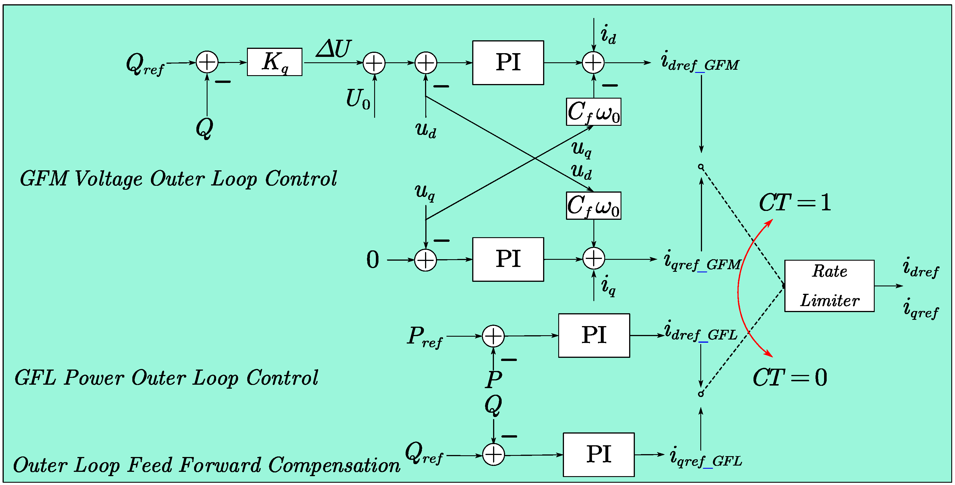
As shown in Figure 6, the switching of the system’s outer-loop feed-forward control strategy is also uniformly triggered by the Mode Switch Signal CT. Its core lies in generating adapted current reference commands according to different operating modes and ensuring a smooth handover of control authority through a smooth transition mechanism. When CT = 0, the system operates in grid-following (GFL) mode, and the outer loop activates power feed-forward control. Aiming to track the grid voltage and power, it generates the reference currents i d r e f _ G F L and i q r e f _ G F L . When CT = 1, the system switches to grid-forming (GFM) mode, and the outer loop activates voltage feed-forward control. By autonomously establishing voltage and frequency reference, the device generates the reference currents i d r e f _ G F M and i q r e f _ G F M , assuming a grid-supporting role like that of traditional power sources. The calculation logics for the reference currents under the two modes can be formulated as follows:
C T = 0   i d r e f _ G F L = ( P P r e f ) K p , P + K i , P s 2 3 P r e f U g i q r e f _ G F L = ( Q Q r e f ) K p , Q + K i , Q s 2 3 Q r e f U g
C T = 1   i d r e f _ G F M = [ K q Q r e f Q u d ] K p , U + K i , U s u q C f ω 0 + i d i q r e f _ G F M = ( 0 u q ) K p , U + K i , U s + u d C f ω 0 + i q
Since the outer loop of GFL mode aims to track the synchronous grid, its dq-axis reference currents i d r e f _ G F L and i q r e f _ G F L can be approximated as quasi-constant values under steady-state conditions (with their time derivatives approaching zero). In contrast, GFM mode must actively establish grid voltage and frequency to support system power balance, causing its outer-loop reference currents i d r e f _ G F M and i q r e f _ G F M to exhibit strongly time-varying characteristics driven by system inertia regulation and power balancing demands. During a direct hard switch between these two modes, the reference currents abruptly change from steady-state constants to dynamic variables, creating command step changes (i.e., i d r e f _ G F L i d r e f _ G F M 0 and i q r e f _ G F L i q r e f G F M 0 represent significant non-zero jumps).
C T = 0         d i d r e f _ G F L d t = 0 ,         d i q r e f _ G F L d t = 0 C T = 1           d i d r e f _ G F M d t 0 ,         d i q r e f _ G F M d t 0
Such a step change directly induces an instantaneous jump in the output current i t via the inductor volt-second balance relationship:
i t = i 0 + 1 L 0 t u c t n l t d t
The abrupt command variation triggers a step in the control voltage u c t n l t , and integration inevitably leads to a current step, thereby exciting severe power spikes and oscillations. According to instantaneous power theory, the sudden current change couples with transient fluctuations in the point-of-common-coupling (PCC) voltages u d and u q , causing substantial high-frequency oscillations in active and reactive power over a short duration. These power spikes disrupt the original power-angle balance of the grid, potentially inducing transient instability in frequency and voltage, thus posing a threat to system security.
To address this, a bidirectional rate limiter is introduced as a soft-switching transition logic, mathematically described as follows:
i r e f ( t ) = s a t d i d t
For the GFM-to-GFL transition scenario, the system detects the falling edge of the CT signal and initiates the rate-limiting logic on the GFL side, allowing the reference current to approach the target value at a controlled slope d i d t . Conversely, for the GFL-to-GFM transition scenario, the system detects the rising edge of the CT signal and activates the rate-limiting logic on the GFM side. This bidirectional rate limiter not only achieves a soft mode transition by smoothly regulating the rate of change of the reference current—eliminating current surges—but also supplies continuous, bumpless i d r e f and i q r e f as precise benchmarks for the subsequent inner-current-loop decoupling control.
For the parameter design of the bidirectional rate limiter, differentiated settings must be applied based on the dynamic characteristics of the two modes. For the GFL-to-GFM transition scenario, since the grid-forming mode requires rapid establishment of voltage support and responsiveness to droop characteristics, the rate limit value R u p should be designed relatively large, typically selected as 1.5 to 2 times the rated current change rate. This balances dynamic response speed with suppression of current surges. Conversely, for the GFM-to-GFL transition scenario, because the grid-following mode requires precise locking of the grid phase and maintaining constant power, the reference current must smoothly converge from dynamic fluctuations to a quasi-steady-state value. Therefore, the rate limit value R d o w n should be designed more gently, usually taking 0.5 to 1 times the rated current change rate. This extends the regulation time to minimize grid-connecting impacts, thereby ensuring a smooth transition during the switching process.
R u p = k I n T s ,       1.5 < k < 2 R d o w n = k I n T s ,       0.5 < k < 1
where T s is the sampling time (referring to the time interval for periodically sampling electrical quantities such as current in digital control scenarios).
While the empirical ranges for R u p and R d o w n provide a practical starting point, a rigorous stability analysis is imperative to elucidate the sensitivity of these parameters. Improper selection can lead to two detrimental extremes: excessive slew rates fail to suppress current surges, while overly restrictive rates compromise synchronization and induce low-frequency oscillations.
To quantify this, we model the rate limiter as a first-order inertia link within the current reference path, where the time constant is inversely proportional to the rate limiter parameter 1 / R . The interaction between the rate limiter and the inner current loop (characterized by bandwidth ω c ) determines the system’s transient response.
First, to ensure effective suppression of current surges during hard switching, the rate limiter must sufficiently slow down the reference variation to match the tracking capability of the inner current loop. The required minimum transition time should satisfy the inductor volt-second balance constraint:
t t r L Δ I r e f V d c
where Δ I r e f is the step change in reference current. Consequently, the upper bound of the rate limit R m a x is constrained by:
R m a x Δ I r e f t t r = V d c L
Exceeding R m a x (too fast) invalidates the soft-switching effect, leading to unsuppressed current spikes. Conversely, if the rate is too small (exceeding the lower bound R m i n ), the prolonged transition time t t r prevents the system from synchronizing with the grid frequency f g r i d . This introduces phase lag ϕ l a g that destabilizes the phase-locked loop (PLL):
ϕ l a g = 2 π f g r i d t t r
When ϕ l a g approaches the phase margin of the PLL, the system loses synchronization, leading to oscillations and potential collapse. Therefore, the stability criterion for the rate limiter is bound by:
R m i n < R < R m a x
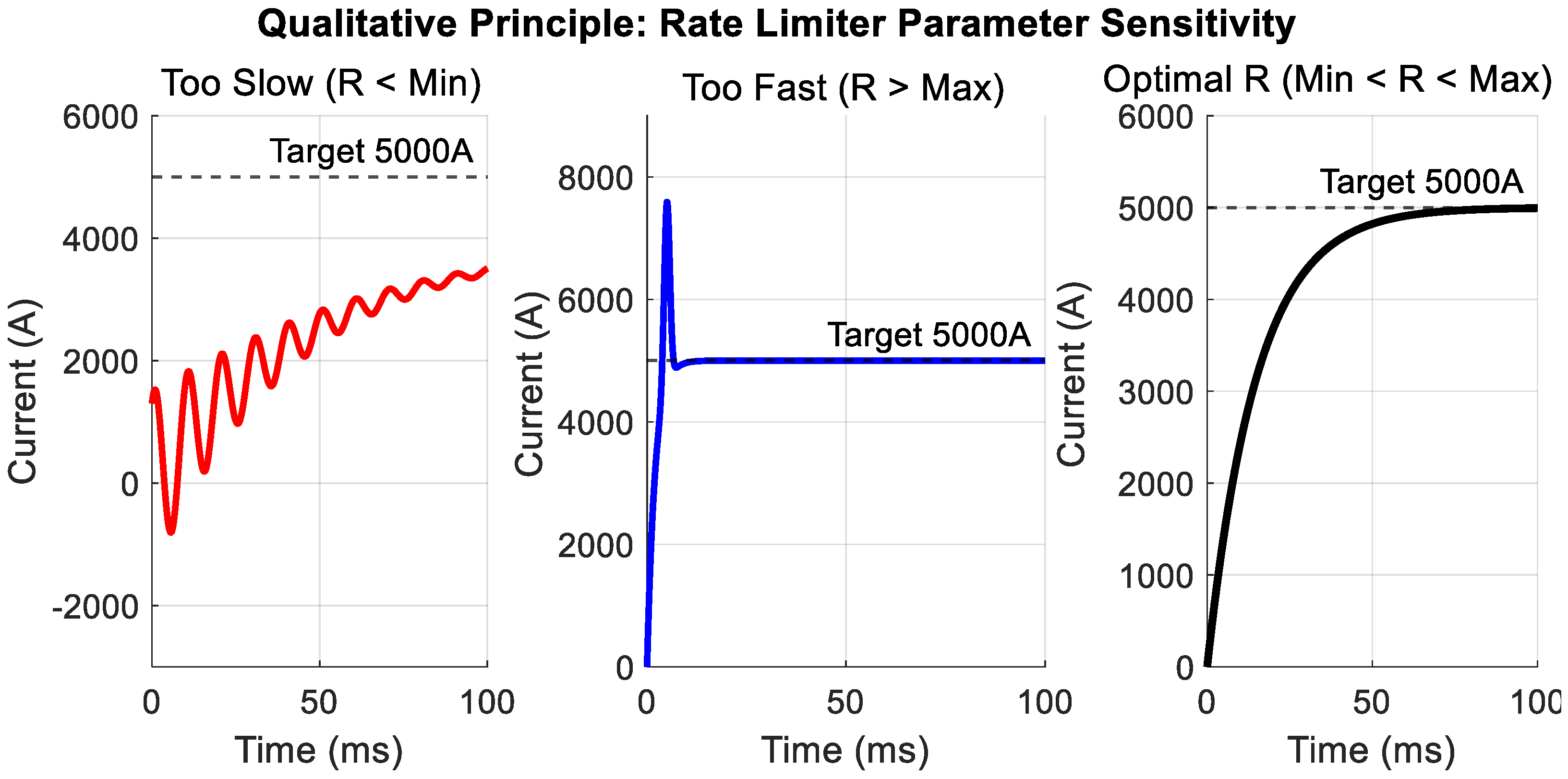
Figure 7 serves as a visual roadmap for parameter tuning, categorizing the system behavior into three distinct operational zones based on the value of the rate limit R . As illustrated, Region I (left) corresponds to an excessively slow transition rate. In this zone, the accumulated phase lag violates the synchronization boundary defined by Equation (19), leading to PLL instability and oscillatory divergence. Conversely, Region II (center) represents an excessively fast transition rate, where the current slew rate surpasses the inductive limit of Equation (18), resulting in severe current surges. Critically, Region III (right) represents the feasible stability zone where the selected balances both constraints, ensuring a bumpless transfer.
To systematically identify the optimal within the stability zone, a bisection search algorithm is employed, leveraging the linear relationship between the rate limit and the transition time. The search is bounded by the theoretical limits and derived from Equations (17) and (18). The algorithm iteratively narrows the search interval by evaluating the transient performance at the midpoint. If the resulting overshoot exceeds the safe margin (Region III tendency), the upper bound is updated; if synchronization fails due to excessive delay (Region I tendency), the lower bound is updated. This iterative process continues until the convergence criterion is met, yielding the optimal that guarantees both surge suppression and PLL stability.
In summary, the designed bidirectional rate limiter constitutes a critical buffer zone connecting the outer-loop feed-forward control and the inner-loop current decoupling. By adaptively regulating the ramp rate of reference current, it effectively eliminates reference command steps caused by control mode switching and suppresses the resulting power spike oscillations and current stress impacts.

4. Experimental Validation

4.1. Real-Time Simulation Setup Based on Typhoon HIL

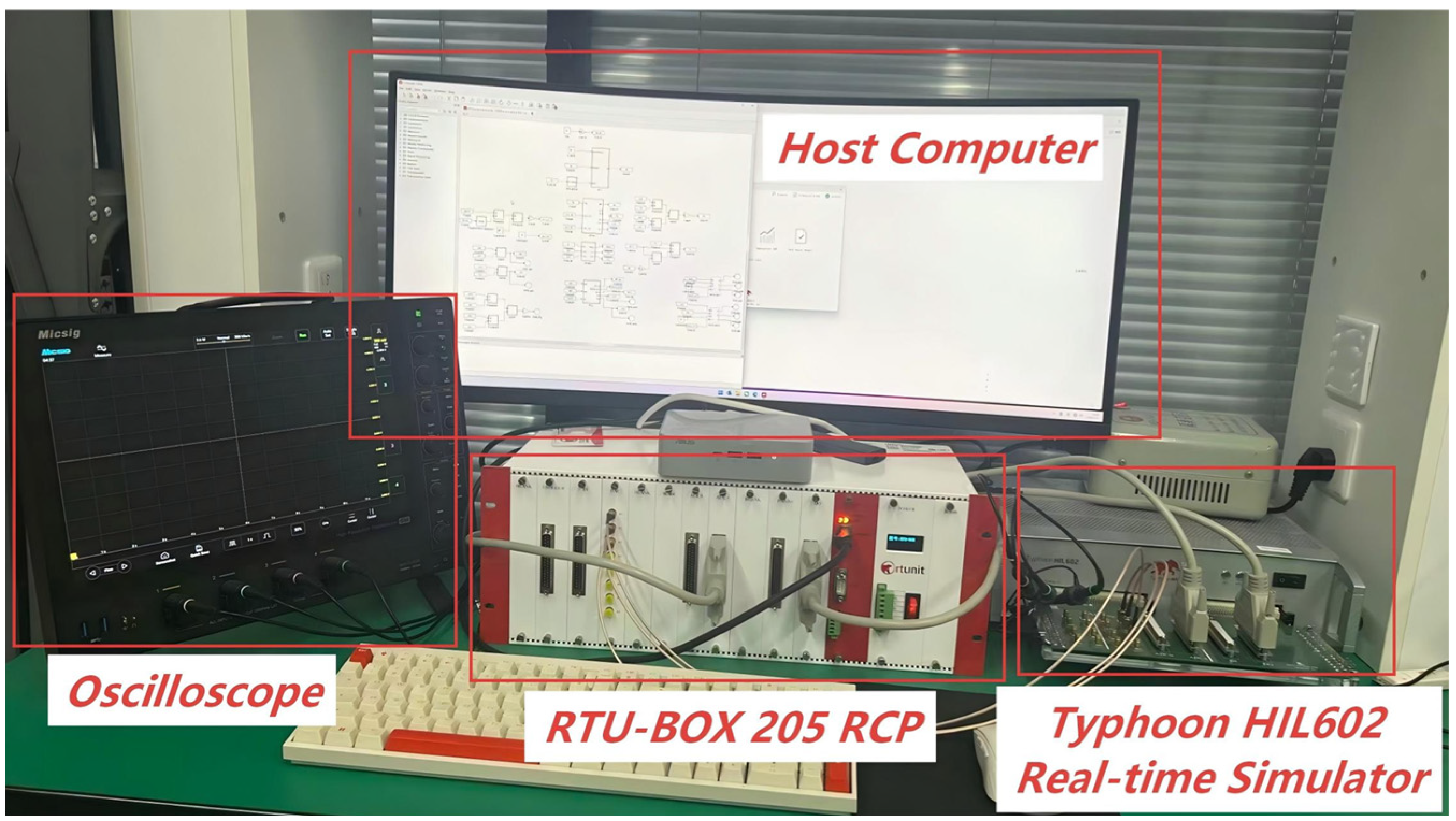
To validate the effectiveness of the proposed seamless switching strategy between grid-following and grid-forming modes for renewable energy and energy storage systems, a Hardware-in-the-Loop (HIL) experimental platform (Typhoon HIL, Inc., Somerville, MA, USA) is established, as shown in Figure 8. The right side of the setup incorporates a Typhoon HIL602 real-time simulator, which models the detailed switching dynamics of the power electronic system. The central component is an RTU-BOX 205 (Rtunit/Nanjing Ruituyoute Information Technology Co., Ltd., Nanjing, China) rapid control prototyping (RCP) system, responsible for executing the control algorithms. The control loop operates at a fixed sampling frequency of 10 kHz, ensuring precise timing synchronization between the controller and the simulator. An oscilloscope, positioned on the left, captures the dynamic response of key signals, while an upper computer located above monitors the real-time operation status. The key parameters of the grid-connected inverter system are summarized in Table 2 below.
To ensure reproducibility and transparency, the parameter tuning follows systematic principles grounded in stability constraints and dynamic performance requirements. The PLL bandwidth is strictly limited to 10–15 Hz to balance synchronization accuracy with harmonic immunity. The GFM droop coefficients are derived from the power-voltage sensitivity of the 2 MW system: the active power droop coefficient is calculated to yield a 5% frequency deviation at full load, while the reactive power droop corresponds to a 5% voltage drop under rated current, emulating the external characteristics of a synchronous machine. For the inner current loop, the proportional gain is tuned to achieve a bandwidth of 500–800 Hz (1/6 to 1/10 of the switching frequency) with a phase margin greater than 60°, and the integral gain is optimized to eliminate steady-state error without exciting the LCL filter resonance. The outer voltage loop bandwidth is set to 1/10th of the current loop bandwidth to ensure a dominant pole configuration. As detailed in Section 3.3, the rate limiter slopes are determined by the inductor volt-second balance and PLL synchronization constraints to prevent transient surges and instability.
To quantitatively evaluate the smoothness and dynamic performance of the mode transition, this study adopts a multi-dimensional assessment framework. Specifically, the active power overshoot is utilized to quantify the transient energy fluctuation, while the overshoot of the filtered phase-A voltage and current is measured to assess power quality degradation. Furthermore, the surge peak values of voltage and current can also be recorded to reflect the severity of instantaneous electrical stress, and the settling time is strictly calculated to determine the speed of system stabilization. These metrics are rigorously extracted from the HIL experimental waveforms to provide an objective benchmark for comparing different control strategies.

4.2. Experimental Analysis of Switching-Induced Instability

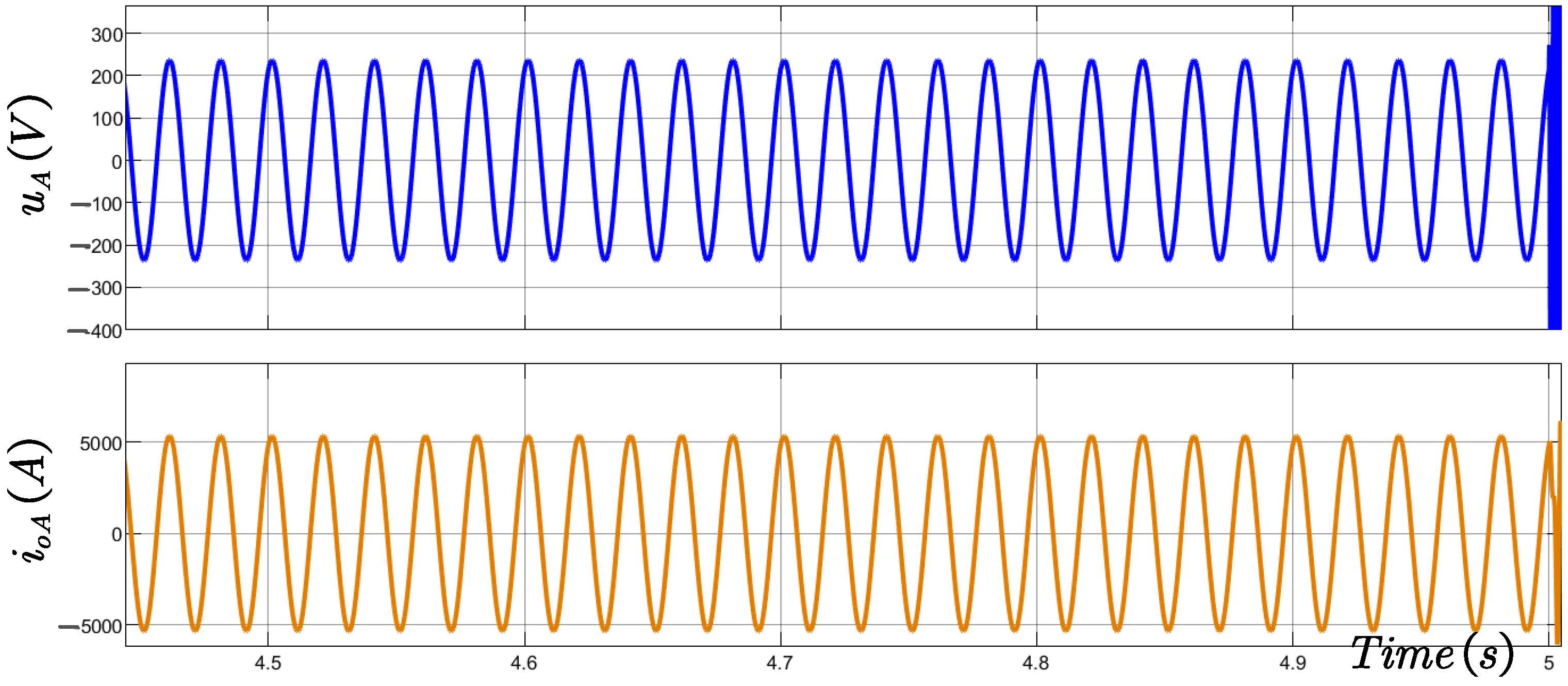
To investigate the dynamic interaction mechanisms during grid-connected mode transitions, this study establishes a single-transition test sequence under a typical weak grid condition (SCR = 2.5). As illustrated in Figure 9, the system initiates Grid-Forming (GFM) mode to establish the voltage and stabilize the local grid. The peak value of the filtered voltage stabilizes at approximately 220 V, while the filtered current peak remains stable at around 5000 A. At t = 5   s , the system receives a dispatch command to switch to Grid-Following (GFL) mode. However, due to the absence of PLL blocking logic, the conflict between the inherited GFM phase reference and the PLL synchronization process leads to immediate system instability, demonstrating that seamless transition is unattainable under such critical conditions without specific control interventions.
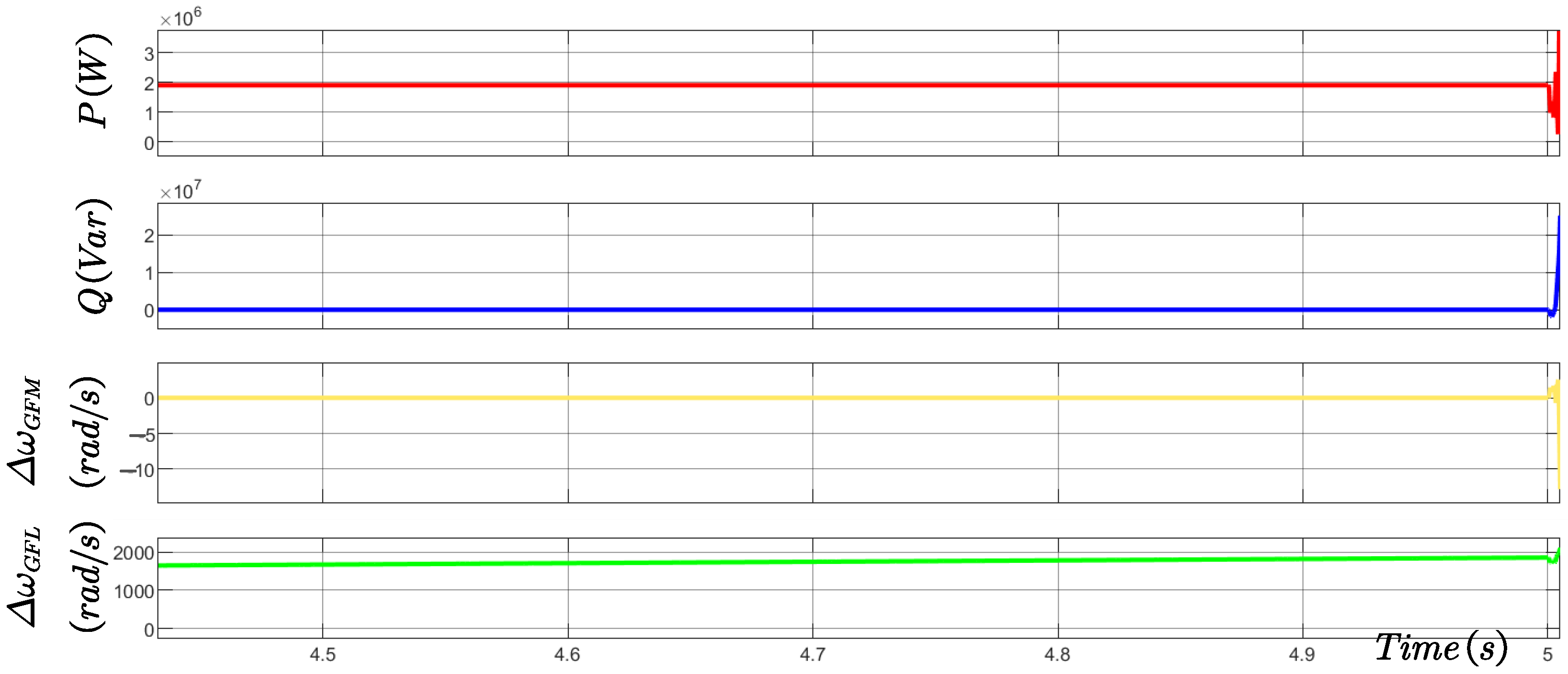
Figure 10 illustrates the dynamic response under the shared current loop architecture without PLL blocking logic. At the instant of switching from GFM to GFL ( t = 5   s ), the PLL remains active during GFM operation, attempting to regulate the q-axis voltage to zero while simultaneously tracking the grid.
Although the GFM mode locks the angular frequency deviation around zero, the GFM-induced angular frequency deviation reaches nearly 2000 rad/s by the end of the 5th second due to the PLL remaining un-bypassed. This extreme frequency deviation far exceeds the allowable limits and directly triggers PLL loss-of-sync, leading to system collapse. This results in a significant step change in the output phase angle, ultimately leading to system instability. This creates a dynamic conflict with the autonomous phase reference generated by the GFM droop control. Such dual-source competition leads to phase-locking failure and power control instability, ultimately triggering system oscillations and loss of synchronization.
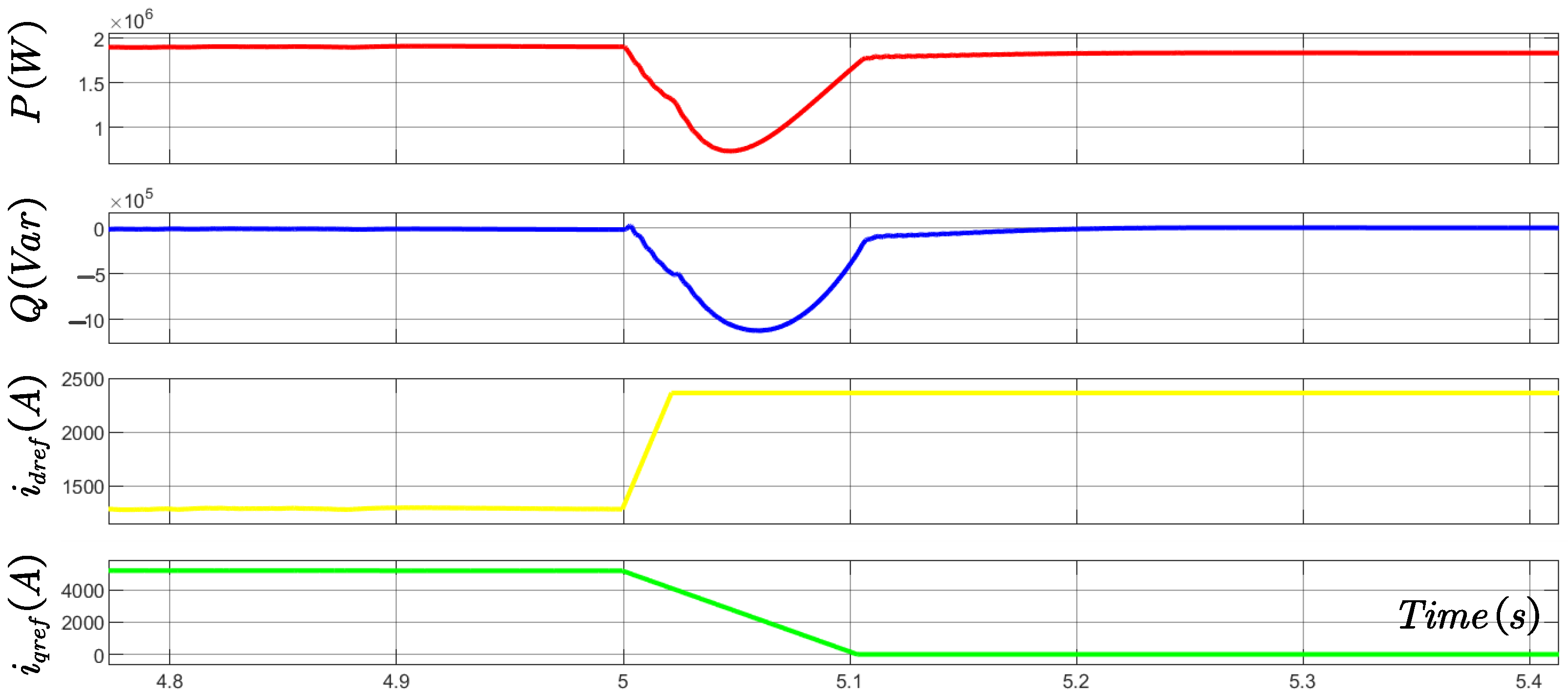
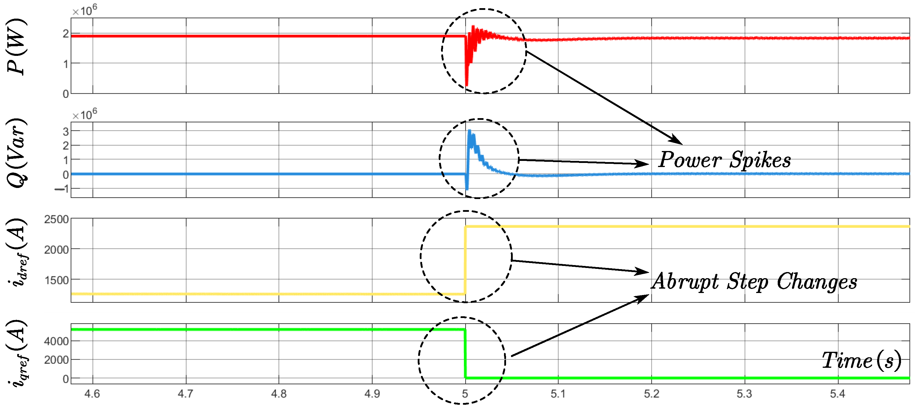
Figure 11 demonstrates the effectiveness of zeroing the PLL input during GFM operation, which successfully suppresses the 2000 rad/s angular frequency deviation observed in Figure 9 and blocks the phase competition path. However, at the switching instants ( t = 5   s ), the reference currents undergo hard switching, resulting in abrupt step changes in the command signals, as quantitatively analyzed below. At the instant of switching between grid-forming and grid-following modes, the q-axis reference current for the inner current loop—generated by the outer loop—plummets from 5000 A to 0 A. This step change inflicts severe transient shocks on the system, triggering power spikes. The active power overshoot reaches 92.7%, with a settling time of approximately 0.1 s.
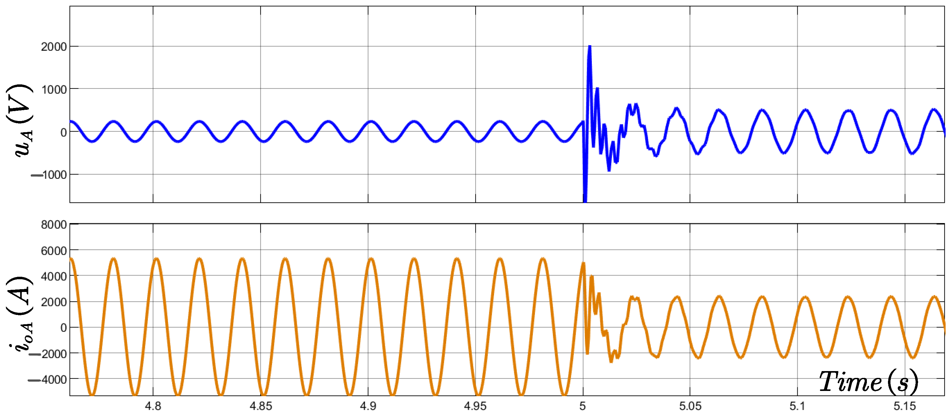
Although the settling time can be reduced to 0.1 s, Figure 12 reveals that the active power overshoot stems fundamentally from the voltage shock at the switching instant. Specifically, the peak voltage value surges to approximately 10 times the steady state value. According to the volt-second balance principle of the inductor, these step changes force abrupt variations in the control voltage, thereby exciting severe current spikes and transient power shocks. This clearly indicates that architectural simplification alone cannot eliminate current stress during dynamic transitions.
Figure 13 and Figure 14 validate the seamless transition and smooth waveforms achieved by the proposed dual soft-switching mechanism, which integrates a shared current inner loop, PLL input blocking, and phase initial-value reinitialization. As shown in Figure 13, the reference currents fed into the inner-loop decoupling are transitioned via a bidirectional rate limiter, effectively eliminating abrupt steps. Quantitatively, this ramp-based transition suppresses the active power overshoot by 51.8% compared to traditional methods, while maintaining the output phase angle continuity.
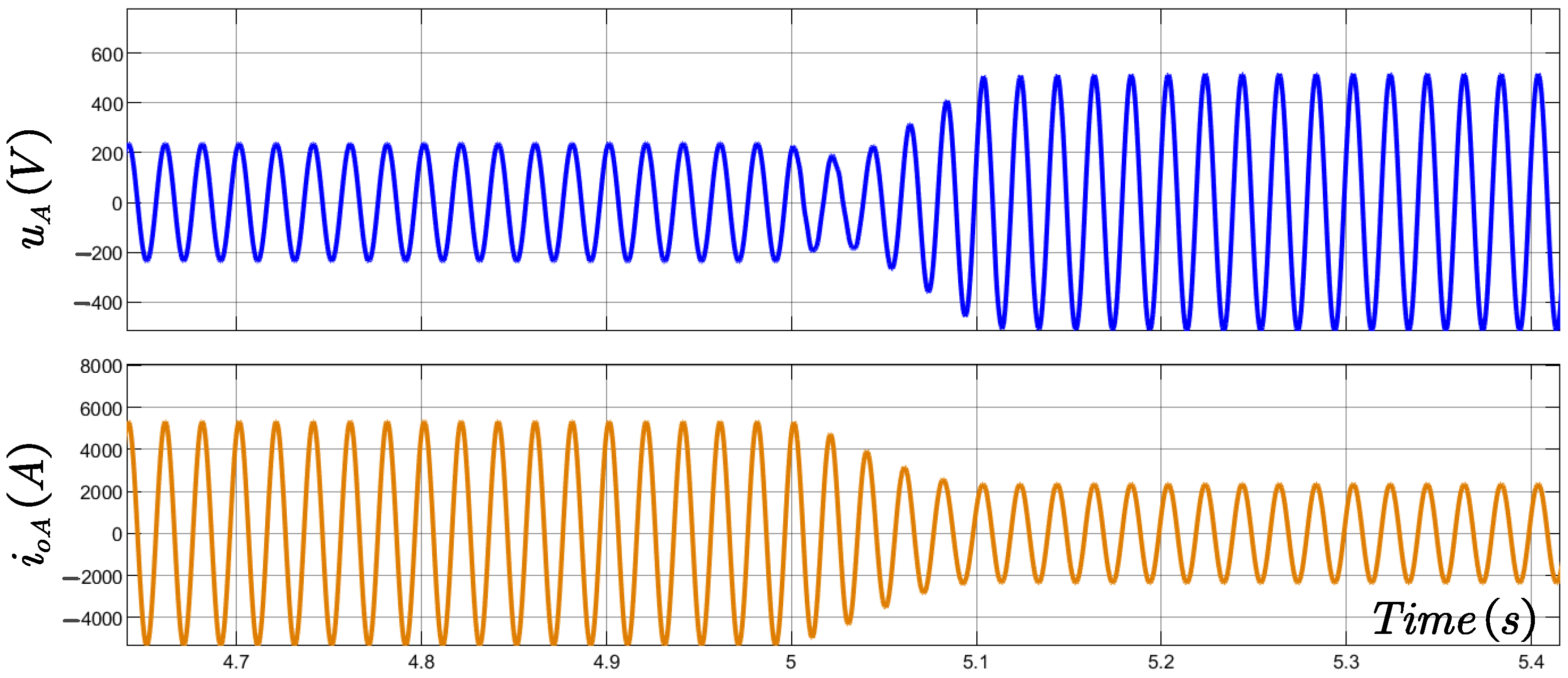
Consequently, as illustrated in Figure 14, the filtered phase-A voltage and current exhibit a completely smooth transition without any voltage spikes or current distortion. The system stabilizes within 0.1 s across multiple GFM/GFL switching events, demonstrating non-overshooting, oscillation-free dynamics and verifying the mechanism’s superiority in ensuring operational stability.
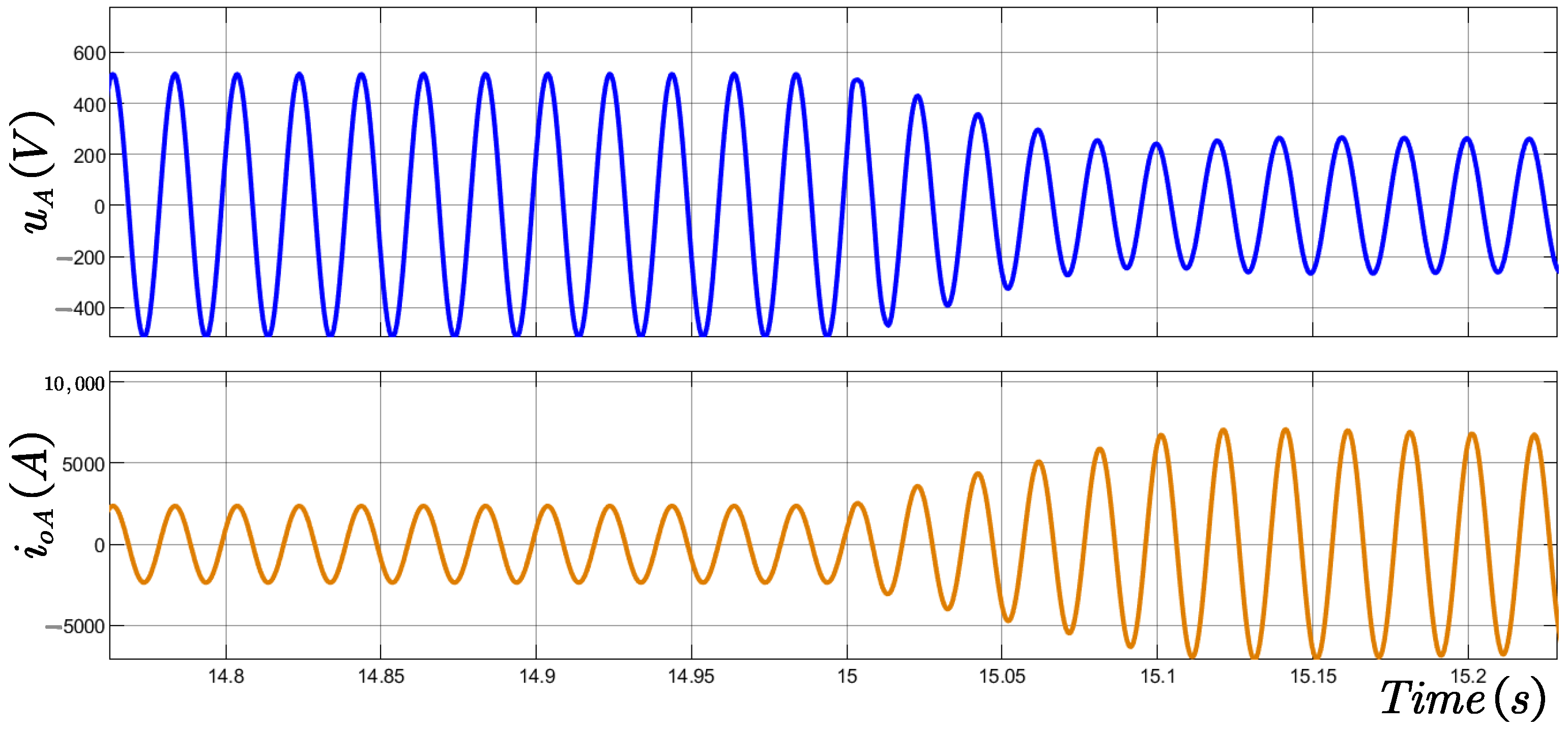
Furthermore, as demonstrated in Figure 15, even when switching back to grid-following mode ( t = 15   s ), the grid-side maintains a perfectly smooth transition without any voltage or current distortion, further validating the effectiveness and robustness of the proposed switching strategy under prolonged operation.

4.3. Performance Evaluation Under Varying Short-Circuit Ratios (SCR)

Although the effectiveness of the proposed dual soft-switching mechanism has been validated under a typical weak grid condition (SCR = 2.5) in the previous sections, the actual grid strength encountered by renewable energy plants is often stochastic, prompting mode transitions based on real-time SCR thresholds rather than predetermined time points. To comprehensively evaluate the robustness of the control strategy across a wide range of grid strengths, this section conducts Short-Circuit Ratio (SCR) parametric sweep experiments. Testing is performed from strong grid to weak grid (SCR = 5 to 2). By utilizing the quantitative metrics defined in Section 4.1—specifically active power overshoot, filtered voltage/current surge peaks, and settling time—this study verifies the universal applicability of the proposed strategy under varying grid impedances.
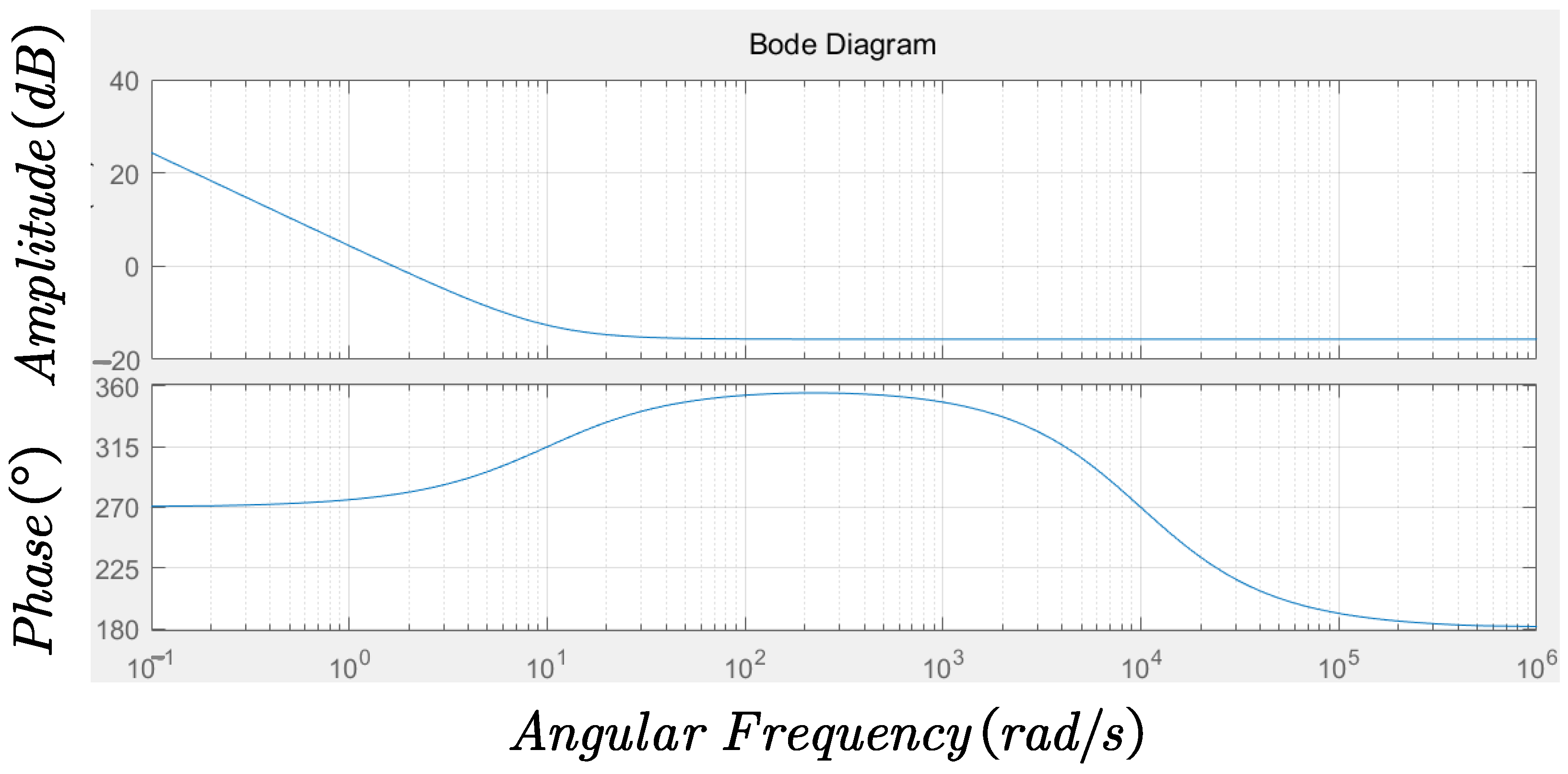
To further verify the robustness under extremely weak grid conditions (SCR = 1.5), Figure 16 presents the open loop Bode plot of the current loop. The analysis reveals that the system maintains a high DC gain for steady-state accuracy and exhibits no resonant peaks. Crucially, the system achieves a phase margin of 99° at the crossover frequency of 1.67 rad/s. Regarding stability limits, the phase never reaches −180°, indicating an infinite gain margin, which confirms that the proposed strategy ensures absolute stability against potential resonance.
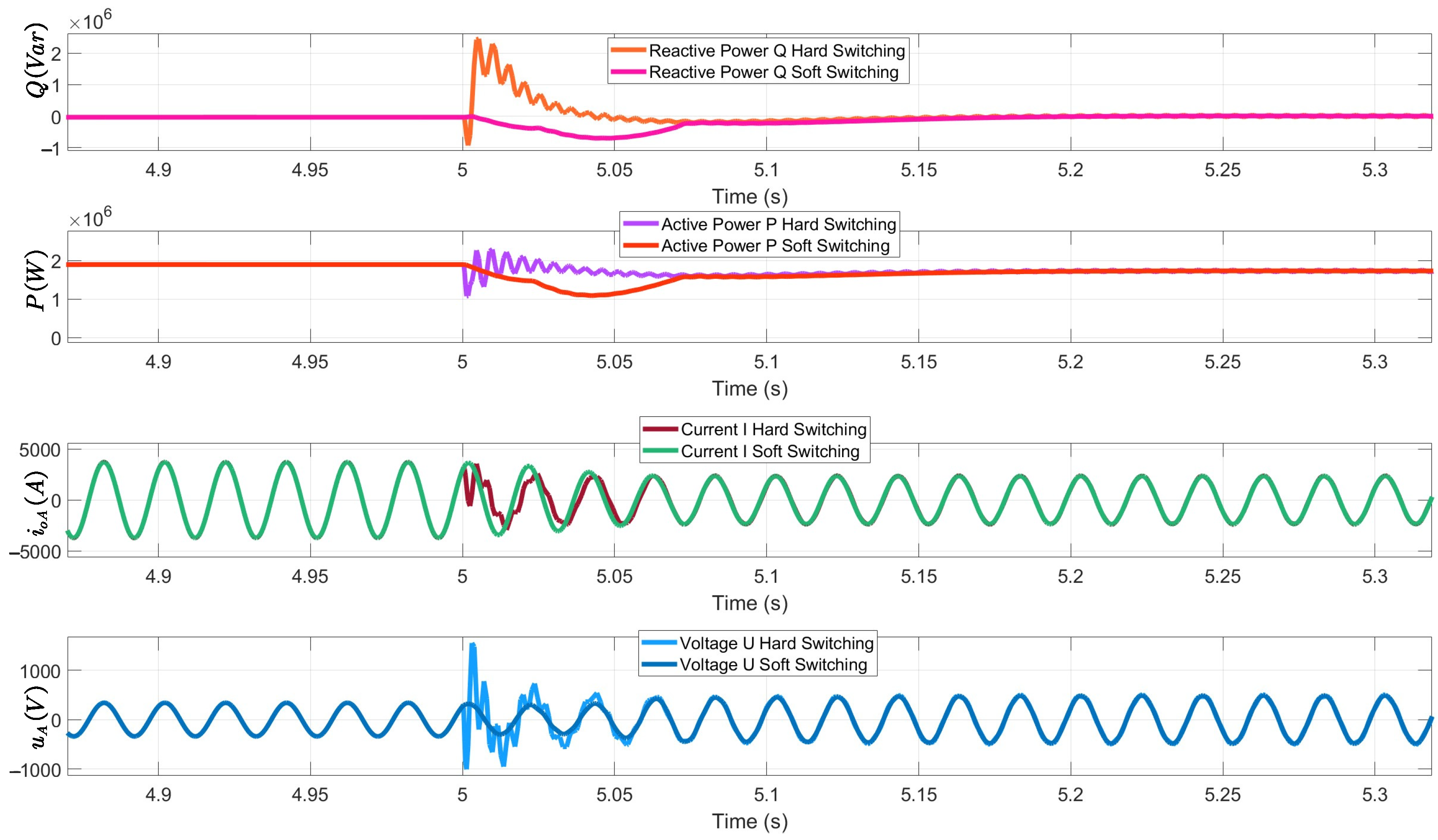
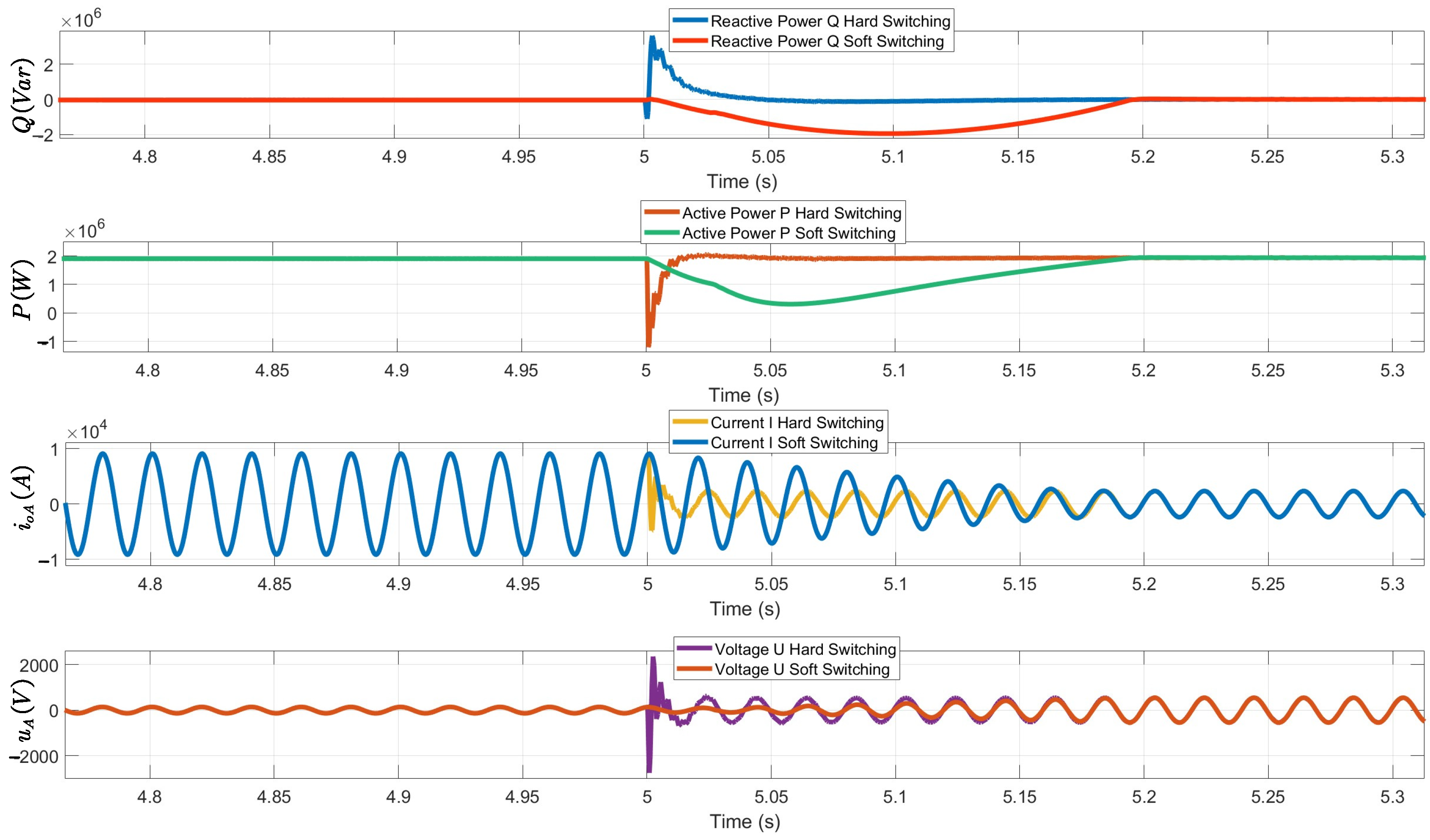
To intuitively demonstrate the superiority of the proposed mechanism across diverse grid strengths, Figure 17 and Figure 18 illustrate the transient wave distortions under SCR = 2 (critical weak grid) and SCR = 4 (moderately strong grid), respectively. As summarized in Table 2, a comprehensive comparison between hard switching and the dual soft-switching strategy reveals significant robustness against SCR variations. As reflected in Table 3, the severity of transient impacts under hard switching exhibits a distinct inverse correlation with grid strength. Specifically, as the SCR decreases from 4 to 2, the active power overshoot drops from 154.6% to 68.2%; however, this is accompanied by prolonged instability, evidenced by the number of distorted cycles escalating from 2 to 4. Conversely, the proposed soft-switching strategy demonstrates unparalleled robustness across all SCR levels. It consistently achieves zero-distortion transitions (0 distorted cycles). Notably, the settling time varies slightly (0.08–0.16 s) depending on the grid strength to balance damping and response speed, yet it always maintains power overshoot within a safe margin (below 72%), regardless of whether the grid is weak (SCR = 2) or strong (SCR = 4). This slight increase in settling time under strong grid conditions is a deliberate trade-off to enhance damping and suppress overshoot, ensuring zero distorted cycles across all SCR levels. This comprehensive suppression validates the strategy’s capability to ensure grid-friendly operations under stochastic grid conditions.

4.4. Discussion

The experimental campaign systematically validates that the proposed dual soft-switching mechanism transcends the limitations of conventional architectures, particularly in addressing the “hidden instability” induced by PLL competition. As evidenced by the HIL results, the integration of PLL input blocking and bidirectional rate limiting is not merely an algorithmic tweak but a fundamental solution to the phase-reference conflict during GFM-to-GFL transitions. The quantitative data in Table 3 further corroborates that the strategy maintains near-constant dynamic performance across a wide SCR spectrum (from 1.5 to 4). Notably, the frequency-domain analysis at SCR = 1.5 reveals an infinite gain margin, which provides a rigorous theoretical guarantee that the system will not excite resonant peaks even under extreme grid impedance variations. This combination of time-domain suppression of distorted cycles and frequency-domain stability margins offers a comprehensive validation package that addresses both the symptoms and root causes of switching instability.
While the current study focuses on symmetrical grid conditions and SCR variations, the discussion would be incomplete without acknowledging the engineering trade-offs involved. The slight variation in settling time (0.08–0.16 s) observed across different SCR levels indicates a necessary balance between damping enhancement and dynamic response speed. For practical deployment, this suggests that the rate-limiter coefficients should be adaptive rather than fixed, potentially linked to real-time grid impedance estimation to optimize performance. Although the present work prioritizes seamless transition under stochastic grid strengths, future extensions could incorporate asymmetrical fault ride-through strategies. Nevertheless, the current findings provide a robust, quantifiable, and industrially viable pathway for renewable energy systems to navigate the complexities of modern weak-grid interconnections.

5. Conclusions

This paper addressed the critical challenge of seamless transitions between Grid-Following (GFL) and Grid-Forming (GFM) modes for grid-connected energy storage systems. By proposing a unified dual-soft switching mechanism, the inherent trade-off between structural complexity and transient performance in conventional methodologies was successfully resolved.
The key contributions are threefold. First, a unified architecture eliminating redundant parallel paths was established. By coordinating PLL input blocking with phase initial-value reinitialization, the conflict between PLL synchronization and GFM autonomous references was mitigated, effectively preventing catastrophic frequency deviations. Second, a bidirectional rate limiter replaced abrupt reference steps. Theoretical analysis identified the optimal parameter zone—avoiding PLL instability caused by small values and current surges from large ones—which resulted in a 51.8% suppression of active power overshoot. Third, comprehensive HIL experiments validated robust performance across a wide SCR range (1.5–4). Unlike conventional methods prone to severe distortion, the proposed strategy ensured zero-distortion transitions and maintained an infinite gain margin at SCR = 1.5, guaranteeing absolute stability.
Future work will focus on extending this mechanism to Virtual Synchronous Generator (VSG) applications. Specific efforts will target the interaction between VSG inertial response and PLL dynamics, the development of adaptive rate limiters coordinated with VSG excitation loops, and physical prototype validation under real-world grid disturbances.

Author Contributions

Conceptualization, J.C. and X.L.; methodology, X.L. and P.W.; software, X.L., Z.W. and P.W.; validation, R.C., J.C. and Z.W.; resources, R.C. and Z.W.; writing—original draft preparation, X.L.; writing—review and editing, Z.W. All authors have read and agreed to the published version of the manuscript.

Funding

This research received no external funding.

Data Availability Statement

The original contributions presented in this study are included in the article. Further inquiries can be directed to the corresponding author.

Conflicts of Interest

The authors declare no conflicts of interest.

Abbreviations

The following abbreviations are used in this manuscript:
GFLGrid-following
GFMGrid-forming
IBRsInverter-based Resources
PCCPoint-of-Common-Coupling
PIProportional Integral
PLLPhase-locked Loop
PWMPulse Width Modulation
SCRShort Circuit Ratio

References

  1. Garg, S.; Tyagi, S. A Comprehensive Review on Opportunities and Challenges of Grid Integration of Renewable Energy Resources. In Proceedings of the 2024 Second International Conference on Smart Technologies for Power and Renewable Energy (SPECon), Ernakulam, India; IEEE: New York, NY, USA, 2024; pp. 1–6. [Google Scholar] [CrossRef]
  2. Mendis, A.; Haque, M.E.; Arif, M.T.; Gargoom, A.; Smith, C.; Aktarujjaman, M. Grid Forming Battery Storage for Stability Enhancement in IBR Rich Grids. In Proceedings of the 2025 IEEE International Conference on Energy Technologies for Future Grids (ETFG), Wollongong, Australia; IEEE: New York, NY, USA, 2025; pp. 1–6. [Google Scholar] [CrossRef]
  3. Zhang, J. Power electronics in future electrical power grids. In Proceedings of the 2013 4th IEEE International Symposium on Power Electronics for Distributed Generation Systems (PEDG), Rogers, AR, USA; IEEE: New York, NY, USA, 2013; pp. 1–3. [Google Scholar] [CrossRef]
  4. Steimer, P.K. Enabled by high power electronics—Energy efficiency, renewables and smart grids. In Proceedings of the 2010 International Power Electronics Conference—ECCE ASIA-, Sapporo, Japan; IEEE: New York, NY, USA, 2010; pp. 11–15. [Google Scholar] [CrossRef]
  5. Cui, X.; Dong, S.; Hoke, A.; Tan, J. A Unified Metric for Fast Frequency Response in Low-Inertia Power Systems. In Proceedings of the 2023 IEEE Power & Energy Society Innovative Smart Grid Technologies Conference (ISGT), Washington, DC, USA; IEEE: New York, NY, USA, 2023; pp. 1–5. [Google Scholar] [CrossRef]
  6. Zhang, C.; Ramasubramanian, D.; Mitra, P.; Singhvi, V. Rapid Stability Screening Method for Fast Frequency Response from IBRs in Weakly Connected Areas. In Proceedings of the 2024 IEEE Power & Energy Society General Meeting (PESGM), Seattle, WA, USA; IEEE: New York, NY, USA, 2024; pp. 1–5. [Google Scholar] [CrossRef]
  7. Ngaha, W.S.; Dorrell, D.; Chandima, G. Hybrid Distributed Model Predictive Control of Flywheel–Battery Energy Storage Systems for Virtual Inertia and Fast Frequency Response. In Proceedings of the 2025 15th International Conference on Power and Energy Systems (ICPES), Chongqing, China; IEEE: New York, NY, USA, 2025; pp. 457–464. [Google Scholar] [CrossRef]
  8. Santamaria, K.S.; Rios, M.A. Challenges of Power Systems with IBR-dominated in Specific Regions: Analysis of Transient Stability and SCR. In Proceedings of the 2025 IEEE Workshop on Power Electronics and Power Quality Applications (PEPQA), Cartagena, Colombia; IEEE: New York, NY, USA, 2025; pp. 1–6. [Google Scholar] [CrossRef]
  9. Tu, Y.; Liu, J.; Liu, T.; Cheng, X. Impedance-Based Stability Analysis of Large-Scale PV Station under Weak Grid Condition Considering Solar Radiation Fluctuation. In Proceedings of the 2018 International Power Electronics Conference (IPEC-Niigata 2018 -ECCE Asia), Niigata, Japan; IEEE: New York, NY, USA, 2018; pp. 3934–3939. [Google Scholar] [CrossRef]
  10. Hu, B.; Zhao, C.; Sahoo, S.; Wu, C.; Chen, L.; Nian, H.; Blaabjerg, F. Synchronization Stability Enhancement of Grid-Following Converter Under Inductive Power Grid. IEEE Trans. Energy Convers. 2023, 38, 1485–1488. [Google Scholar] [CrossRef]
  11. Feng, Z.; Lingyue, K.; Jie, Z.; Chao, S.; Donghui, J.; Xinbo, L. Stabilization Control Strategy of GFL Wind Converters during LVRT Under Weak Grid Conditions. In Proceedings of the 2025 9th International Conference on Power and Energy Engineering (ICPEE), Chengdu, China; IEEE: New York, NY, USA, 2025; pp. 225–229. [Google Scholar] [CrossRef]
  12. Kannan, A.; Lipiec, K.; Hanel, L.; Würflinger, K.; Shevchenko, M.; Soergel, A.; Winter, P.; Neumann, T.; Vennemann, K.; Hennig, T.; et al. Performance of Grid Forming Compared to Grid Following STATCOM in Weak Power Systems. In Proceedings of the 2024 IEEE PES Innovative Smart Grid Technologies Europe (ISGT EUROPE), Dubrovnik, Croatia; IEEE: New York, NY, USA, 2024; pp. 1–5. [Google Scholar] [CrossRef]
  13. Fan, Z.; Wang, F.; Hu, S.; Fan, Y.; Jiang, X.; Liu, X.; Tang, J. Research on the Grid-Forming Control Strategy for the PCS of Energy Storage System. In Proceedings of the 2025 IEEE PES Innovative Smart Grid Technologies—Asia (ISGT Asia), Guangzhou, China; IEEE: New York, NY, USA, 2025; pp. 357–360. [Google Scholar] [CrossRef]
  14. Liu, M.; Zeng, G.; He, X.; Tu, L.; He, P.; Zhu, Y. Grid-forming Control of VSC-HVDC Systems Connecting Asynchronous Power Grids. In Proceedings of the 2024 4th Power System and Green Energy Conference (PSGEC), Shanghai, China; IEEE: New York, NY, USA, 2024; pp. 302–306. [Google Scholar] [CrossRef]
  15. Yang, B.; Zhou, X.; Zhao, Z.; Zhang, Y.; Li, N. A Smooth Mode Switching Strategy Between Grid-forming and Grid-following Controls. In Proceedings of the 2026 IEEE PES International Meeting (PES IM), Hong Kong, Hong Kong; IEEE: New York, NY, USA, 2026; pp. 1–5. [Google Scholar] [CrossRef]
  16. Jiang, G.; Kan, S.; Li, Y.; Zhu, X. Disturbance-Free Switching Control Strategy for Grid-Following/Grid-Forming Modes of Energy Storage Converters. Electronics 2025, 14, 3963. [Google Scholar] [CrossRef]
  17. Gao, X.; Zhou, D.; Anvari-Moghaddam, A.; Blaabjerg, F. Seamless Switching Method Between Grid-Following and Grid-Forming Control for Renewable Energy Conversion Systems. IEEE Trans. Ind. Appl. 2024, 61, 597–606. [Google Scholar] [CrossRef]
  18. Zhou, Y.; Cao, W.; Sun, L.; Wang, S. Flexible Transition Strategy for Grid-Connected Vsc Between Grid-Following and Grid-Forming Operation Modes. In Proceedings of the 2025 11th International Conference on Energy Materials and Electrical Engineering (ICEMEE), Nyingchi/Tibet, China; IEEE: New York, NY, USA, 2025; pp. 35–39. [Google Scholar] [CrossRef]
  19. Sadeque, F.; Sharma, D.; Mirafzal, B. Seamless Grid-Following to Grid-Forming Transition of Inverters Supplying a Microgrid. In Proceedings of the 2023 IEEE Applied Power Electronics Conference and Exposition (APEC), Orlando, FL, USA; IEEE: New York, NY, USA, 2023; pp. 594–599. [Google Scholar] [CrossRef]
  20. Du, J.; Zhang, H.; Chen, A.; Cheng, C.; Tang, H.; Li, J.; Liu, M.; Li, J. Seamless Switching Strategy Between Grid-Following and Grid-Forming Control Methods for Grid-Connected Inverters. In Proceedings of the 2025 IEEE Energy Conversion Conference Congress and Exposition (ECCE), Philadelphia, PA, USA; IEEE: New York, NY, USA, 2025; pp. 1–6. [Google Scholar] [CrossRef]
  21. Naresh, P.; Anirudh, C.; Kumar, V.S.S. Comparison of Passive Damping based LCL Filter Design Methods for Grid-connected Voltage Source Converters. In Proceedings of the 2020 International Conference on Power, Instrumentation, Control and Computing (PICC), Thrissur, India; IEEE: New York, NY, USA, 2020; pp. 1–6. [Google Scholar] [CrossRef]
  22. Liu, Y.; Deng, X.; Zhu, F. A DC-Link Voltage Feedforward Control Strategy of Grid-Forming Wind Turbine Based on Intelligent Wind Speed Prediction. In Proceedings of the 1st Electrical Artificial Intelligence Conference, Volume 2; Qu, R., Song, Z., Ding, Z., Mu, G., Xiong, R., Han, L., Eds.; EAIC 2024; Lecture Notes in Electrical Engineering; Springer: Singapore, 2025; Volume 1395. [Google Scholar] [CrossRef]
  23. Mahdizadeh, A.H.; Tavan, M.; Soltani, M.; Blaabjerg, F.; Hajizadeh, A.; Tricoli, P. Dc-link voltage regulation in all-DC offshore wind farms. Electr. Eng. 2026, 108, 247. [Google Scholar] [CrossRef]
  24. Peña-Alzola, R.; Liserre, M.; Blaabjerg, F.; Sebastián, R.; Dannehl, J.; Fuchs, F.W. Analysis of the Passive Damping Losses in LCL-Filter-Based Grid Converters. IEEE Trans. Power Electron. 2012, 28, 2642–2646. [Google Scholar] [CrossRef]
  25. Zhao, H.; Wu, W.; Orabi, M.; Koutroulis, E.; Chung, H.S.-H.; Blaabjerg, F. A Passive Damping Design Method of Three-phase Asymmetric-LCL Power filter for Grid-Tied Voltage Source Inverter. In Proceedings of the 2023 IEEE Energy Conversion Congress and Exposition (ECCE), Nashville, TN, USA; IEEE: New York, NY, USA, 2023; pp. 94–98. [Google Scholar] [CrossRef]
  26. Bazargan, D.; Bahrani, B.; Filizadeh, S. Reduced Capacitance Battery Storage DC-Link Voltage Regulation and Dynamic Improvement Using a Feedforward Control Strategy. IEEE Trans. Energy Convers. 2018, 33, 1659–1668. [Google Scholar] [CrossRef]
  27. IEEE P2030.2.1/D9.0; IEEE Draft Guide for Design, Operation, and Maintenance of Battery Energy Storage Systems, both Stationary and Mobile, and Applications Integrated with Electric Power Systems. IEEE: New York, NY, USA, 2019.
  28. Wu, Q.; Xu, T.; Ge, Y.; Chen, Y.; Zhang, Q.; Lin, Q. Based on the Autotransformer PI Three-Phase Phase-Locked Loop Control. In Proceedings of the 12th Frontier Academic Forum of Electrical Engineering (FAFEE2025); Yang, Q., Ed.; FAFEE 2025; Lecture Notes in Electrical Engineering; Springer: Singapore, 2026; Volume 1504. [Google Scholar] [CrossRef]
  29. Mohiuddin, S.M.; Du, W.; Liu, Y. Examining the Feasibility of Modeling the Inner Current Control Loop of a Grid-Following Inverter in the Phasor-Based Solver. In Proceedings of the 2023 IEEE Power & Energy Society General Meeting (PESGM), Orlando, FL, USA; IEEE: New York, NY, USA, 2023; pp. 1–5. [Google Scholar] [CrossRef]
  30. Zhao, H.; Lyu, S.; Wang, B.; Wang, R. A DFIG impedance reshaping method based on dynamic compensation of rotor current to enhance the stability in the mid-frequency band. Sci. Rep. 2025, 15, 29124. [Google Scholar] [CrossRef] [PubMed]
  31. Li, S.; Gong, J. Impact of DFIG integrated power system on VSG stability based on damping torque analysis with mode decoupling. Electr. Eng. 2025, 107, 12547–12561. [Google Scholar] [CrossRef]
  32. Ruderman, A. Three-phase multi-level PWM rectifier multi-carrier discontinuous voltage modulation strategy. In Proceedings of the 2007 European Conference on Power Electronics and Applications, Aalborg, Denmark; IEEE: New York, NY, USA, 2007; pp. 1–9. [Google Scholar] [CrossRef]
  33. Moustafa, S.H.; Taha, R.A.; Ibrahim, A.M.; Soliman, A.S.; Amin, M.M.; Mohammad, O.A. Dynamic Droop-Controlled Grid-Forming Inverter Strategy for Stable Power Sharing in PV-Integrated AC Islanded Microgrids. In Proceedings of the 2025 IEEE International Conference on Environment and Electrical Engineering and 2025 IEEE Industrial and Commercial Power Systems Europe (EEEIC/I&CPS Europe), Chania, Crete, Greece; IEEE: New York, NY, USA, 2025; pp. 1–5. [Google Scholar] [CrossRef]
  34. Hou, X.; Sun, Y.; Fu, S.; Chen, S.; Su, M. Revisiting Droop Control and Virtual Impedance Method. In Self-Organized Operation and Stability Control of Electronized Power Networks; Springer: Singapore, 2025. [Google Scholar] [CrossRef]
  35. Minetti, M.; Rosini, A.; Denegri, G.B.; Bonfiglio, A.; Procopio, R. An Advanced Droop Control Strategy for Reactive Power Assessment in Islanded Microgrids. IEEE Trans. Power Syst. 2022, 37, 3014–3025. [Google Scholar] [CrossRef]
  36. Diouf, A.; Noro, Y. A Hybrid Islanding Detection Technique using Voltage Positive Feedback and Frequency Deviation in GFM based Microgrid. In Proceedings of the 2024 IEEE PES/IAS PowerAfrica, Johannesburg, South Africa; IEEE: New York, NY, USA, 2024; pp. 1–5. [Google Scholar] [CrossRef]
  37. Li, M.; Zhang, X. Hybrid Dual-Mode Control for Grid-Following and Grid-Forming Inverters in High-Penetration Renewable Energy System. In Proceedings of the 2023 International Conference on Power and Renewable Energy Engineering (PREE), Tokyo, Japan; IEEE: New York, NY, USA, 2023; pp. 138–143. [Google Scholar] [CrossRef]
  38. Wang, T.; Zhang, X. Dynamic Mode Switching Control Architecture for Grid-Following/Forming Converters in High Renewable Penetration MMC-HVDC Systems. In Proceedings of the 2025 International Conference on New Power System Technology (PowerCon), Hefei, China; IEEE: New York, NY, USA, 2025; pp. 1–6. [Google Scholar] [CrossRef]
  39. Seo, G.-S.; Wang, W.; Mirafzal, B. Microgrid Black Start Challenges: The Role of Grid-Forming Inverters. IEEE Access 2025, 13, 198087–198101. [Google Scholar] [CrossRef]
  40. Shi, C.; Wei, T.; Wu, L.; Zhang, T. The Research on Seamless Switching Control Strategy for Micro-grid Integrating Photovoltaic and Energy Storage. In Proceedings of the IECON 2019—45th Annual Conference of the IEEE Industrial Electronics Society, Lisbon, Portugal; IEEE: New York, NY, USA, 2019; pp. 3949–3955. [Google Scholar] [CrossRef]
Figure 1. Main Power Circuit Topology.
Electronics 15 02315 g001
Figure 2. Grid-Following Control Framework.
Electronics 15 02315 g002
Figure 3. Grid-Forming Control Framework.
Electronics 15 02315 g003
Figure 4. Unified Framework Based on Grid-Following and Grid-Forming Controls.
Electronics 15 02315 g004
Figure 5. Schematic Diagram of Seamless Phase Angle Switching.
Electronics 15 02315 g005
Figure 6. Schematic Diagram of Seamless Outer-Loop Feed-Forward Control Switching.
Electronics 15 02315 g006
Figure 7. Impact of Rate Limiter Settings on System Stability and Transient Response.
Electronics 15 02315 g007
Figure 8. Photograph of the HIL Experimental Platform.
Electronics 15 02315 g008
Figure 9. Instability during GFM-to-GFL transition without PLL blocking (Blue: Filtered phase-A voltage, Orange: Filtered phase-A current) GFM to GFL.
Electronics 15 02315 g009
Figure 10. Instability during GFM-to-GFL transition without PLL blocking (Red: Active Power, Blue: Reactive Power, Yellow: Δ ω   o f   G F M , Green: Δ ω   o f   G F L ) GFM to GFL.
Electronics 15 02315 g010
Figure 11. Transient impacts and power spikes under hard switching with PLL blocking (Red: Active Power, Blue: Reactive Power, Yellow: i d r e f before inner current decoupling loop, Green: i q r e f before inner current decoupling loop) GFM to GFL.
Electronics 15 02315 g011
Figure 12. Transient impacts and power spikes under hard switching with PLL blocking (Blue: Filtered phase-A voltage, Orange: Filtered phase-A current) GFM to GFL.
Electronics 15 02315 g012
Figure 13. Seamless transition and smooth waveforms enabled by the dual soft-switching mechanism (Red: Active Power, Blue: Reactive Power, Yellow: i d r e f before inner current decoupling loop, Green: i q r e f before inner current decoupling loop) GFM to GFL.
Electronics 15 02315 g013
Figure 14. Seamless transition and smooth waveforms enabled by the dual soft-switching mechanism (Blue: Filtered phase-A voltage, Orange: Filtered phase-A current) GFM to GFL.
Electronics 15 02315 g014
Figure 15. Seamless transition and smooth waveforms enabled by the dual soft-switching mechanism (Blue: Filtered phase-A voltage, Orange: Filtered phase-A current) GFL to GFM.
Electronics 15 02315 g015
Figure 16. Bode diagram of the current inner loop under the SCR = 1.5 extremely weak grid condition.
Electronics 15 02315 g016
Figure 17. Transient Impact of Hard Switching versus Smooth Transition of Soft Switching under SCR = 2 from GFM to GFL.
Electronics 15 02315 g017
Figure 18. Transient Impact of Hard Switching versus Smooth Transition of Soft Switching under SCR = 4 from GFM to GFL.
Electronics 15 02315 g018
Table 1. Comparison of Existing Transition Methods and the Proposed Strategy.
Control Structure
& Complexity
Transition
Mechanism
PLL Handling
During Transient
Limitations Solved
by This Work
Single Path with
Complex Logic
Power correction basedRisks synchronization
instability
Simplified dual-soft
mechanism replaces
complex correction loops
Dual loop
Cooperative Scheme
S-shaped weighting
blending
Maintains PLL tracking.
(prone to phase lag)
Eliminates excessive
parallel paths to reduce
computational overhead
Semi-parallel
Control Paths
Unidirectional
(From GFL to GFM)
Resets/re-synchronizes.
(causes delay)
Introduces bidirectional
rate limiting for
true seamless transition
Trade-off
between GFL/GFM
Mode switching
based on grid strength
Standard PLL (struggles
with dynamics)
Unified architecture
with PLL blocking
ensures robust performance
Proposed Method:
Unified Dual-soft
Architecture
Bidirectional
soft switching
PLL input blocking
plus Phase initialization
Balances low complexity with
high dynamic performance
Table 2. Parameters of the Grid-Connected Inverter.
ParameterValueParameterValue
Rated System Capacity2 MWRated AC Voltage690 V/p.u.
Rated Frequency50 HzFilter Inductance75.774 μH
Filter Capacitance 534.86 μFGrid Inductance 757.74 μH
Filter Resistance0.1 ohmRated DC Voltage1500 V
GFM Active Power Ref1.9 MWGFM Reactive Power Ref 0 Mvar
Active Droop Coefficient1.571 rad/MWReactive Droop Coefficient48.79 V/Mvar
GFL d-axis Current Ref 2366.7 AGFL q-axis Current Ref 0 A
Battery Current Limit2840 ASOC Operation Range10–90%
Total Controller Delay200 μsSwitching Frequency 3 kHz
Table 3. Quantitative Evaluation of Transient Performance under Different SCR Conditions.
Performance
Evaluation
SCR = 2SCR = 2.5 (from Section 4.1)SCR = 4
Hard SwitchSoft SwitchHard SwitchSoft SwitchHard SwitchSoft Switch
ActivePower
Overshoot
68.2%43.4%92.7%51.8%154.6%71.1%
Number of
DistortedCycles
403020
VoltageSurge Peak Value (Multiple)51101201
Settling Time0.080.080.100.120.060.16
Disclaimer/Publisher’s Note: The statements, opinions and data contained in all publications are solely those of the individual author(s) and contributor(s) and not of MDPI and/or the editor(s). MDPI and/or the editor(s) disclaim responsibility for any injury to people or property resulting from any ideas, methods, instructions or products referred to in the content.