Article

Reusing Wireless Power Transfer for Backscatter-Assisted Pairwise Cooperation in Multi-User WPCNs


School of Integrated Circuit, Shenzhen Polytechnic University, Shenzhen 518055, China
*
Authors to whom correspondence should be addressed.
Electronics 2026, 15(10), 2227; https://doi.org/10.3390/electronics15102227
Submission received: 25 April 2026 / Revised: 16 May 2026 / Accepted: 18 May 2026 / Published: 21 May 2026
(This article belongs to the Special Issue Advances in Wireless Power Transfer)

Abstract

This paper studies a backscatter-assisted pairwise cooperation scheme in a multi-user wireless powered communication network (WPCN), where pairs of wireless devices (WDs) first harvest wireless energy from an energy node (EN) and then transmit their information to an access point (AP). Under the proposed scheme, the two WDs in each pair first exchange their local messages and then cooperatively transmit to the AP in the uplink. To reduce the time and energy consumption of local information exchange, we exploit the short distance between paired users and realize message exchange through energy-conserving backscatter communication. Meanwhile, the proposed design effectively reuses the wireless power transfer (WPT) signal to enable simultaneous information exchange during the energy harvesting phase, thereby leaving more time and harvested energy for the subsequent cooperative uplink transmission. Based on this transmission protocol, we jointly optimize the time allocation, the user transmit power allocation, and the energy beamforming matrix at the EN to maximize the weighted sum rate. To tackle the resulting non-convex problem, we decompose it into two coupled subproblems and develop an alternating optimization algorithm to update the corresponding variables iteratively. Numerical results show that the proposed scheme achieves significant weighted sum rate improvement over representative benchmark methods.

1. Introduction

Wireless powered communication networks (WPCNs) have attracted considerable attention as a promising solution to the energy supply limitation of low-power wireless devices [1,2,3,4]. In such networks, wireless devices (WDs) rely on radio-frequency energy harvesting to sustain their information transmission, which makes WPCNs particularly attractive for low-power sensing and Internet of Things applications. A representative transmission strategy is the harvest-then-transmit protocol, where each WD first harvests energy in the downlink (DL) and then transmits its information in the uplink (UL) by using the harvested energy [5]. However, the performance of this protocol is fundamentally constrained by the doubly near–far problem in WPCNs. Since the efficiency of wireless power transfer (WPT) degrades rapidly with distance, users farther away from the energy source generally harvest less energy, while they need more communication resources to deliver information to the hybrid access point. This makes efficient transmission design and performance improvement particularly challenging in multi-user WPCNs, which has motivated various performance enhancement techniques, e.g., multi-antenna energy beamforming [6], IRS-assisted transmission [7], and hybrid modulation scheme [8]. To improve the communication performance of disadvantaged users, user cooperation has been widely studied in WPCNs. For example, [9] investigated a two-user cooperative WPCN in which one user helps forward the message of the other user to the access point (AP). In [10], a WPCN with separate energy and information nodes was considered, where two cooperating WDs were allowed to form a distributed virtual antenna array for joint UL transmission. Ref. [11] studied optimal transceiver design and relay selection for a two-hop cooperative simultaneous wireless information and power transfer network with energy constraints at the receiver. Ref. [12] extended user cooperation to a multi-user case and proposed a cluster-based cooperation scheme, where users are organized into clusters, and one user is selected as the cluster head to collect and forward the messages of the remaining cluster members.
A key bottleneck of user cooperation in WPCNs lies in the time and energy cost of local information exchange among cooperating users. Ambient backscatter communication provides a promising technique to reduce such cooperation overhead [13,14]. Specifically, by reflecting the incident RF signal to convey information, a WD can communicate with another WD in a passive manner without generating carrier signals locally, and thus consumes much less energy than conventional active RF transmission. Several studies have investigated ambient backscatter communication from various aspects, including signal detection [15], circuit implementation [16], modulation design [17], and throughput analysis [18]. In particular, prior results have shown that backscatter communication can achieve reliable short-range information exchange with low hardware complexity, which makes it well suited for cooperation between closely located users [19]. Nevertheless, conventional ambient backscatter communication is inherently constrained by the randomness of ambient RF sources in both signal strength and time availability. In WPCNs, this issue can be naturally mitigated, since the incident WPT signal can serve as a dedicated and controllable carrier for backscatter-based local information exchange.
The integration of WPT and backscatter communication provides a more suitable framework for low-power cooperative transmission and has motivated a number of studies on backscatter-assisted cooperation in wireless-powered systems. For instance, ref. [20] studied an energy-beacon-powered backscatter-assisted relay system, where each backscatter device relies on harvested energy for transmission rather than onboard batteries, and the remaining devices serve as relays. In [21], the authors developed a relay selection scheme for a backscatter-aided system, where a device beyond the coverage area communicates with the HAP through backscatter relays powered by energy beamforming. In [22], a user first backscatters its information to both a relay and a receiver, and the relay then actively forwards the information after harvesting energy from the carrier emitter. Furthermore, ref. [23] studied a backscatter-enhanced cooperative transmission in a two-user WPCN, in which one user uses backscatter transmission and the other follows the harvest-then-transmit protocol. More recently, backscatter-assisted wireless-powered networks have also been extended to user-cooperative MEC systems in [24] and multi-backscatter WPCNs for green IoT applications in [25]. However, most existing studies on backscatter-assisted user cooperation still focus on relay-based or two-user scenarios. In these works, active RF transmission and backscatter communication are usually designed separately, whereas in multi-user pairwise cooperation, the incident WPT signal can be naturally reused for local message exchange within each user pair. Meanwhile, the harvested energy can be preserved for subsequent cooperative UL transmission. This makes it possible to integrate passive local information exchange and active cooperative transmission into the same framework. As a result, the passive and active transmission phases need to be jointly designed to fully exploit both the energy-saving advantage of backscatter communication and the cooperation gain in the UL. Nevertheless, existing studies have not yet provided a detailed investigation of this issue.
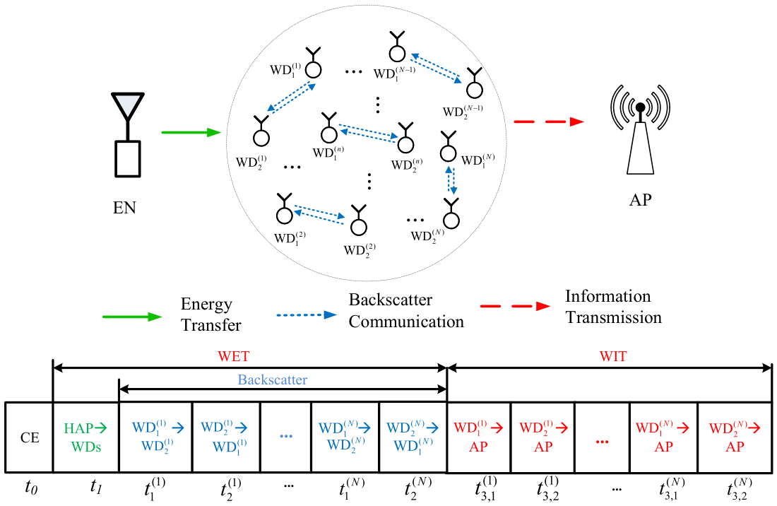
This study focuses on a backscatter-assisted pairwise cooperation scheme in a multi-user WPCN. As shown in Figure 1, the WDs are grouped into disjoint pairs, where the two WDs in each pair exchange their local messages by reusing the incident WPT signal through passive backscatter communication during the DL WPT phase, and then cooperatively transmit their information to the AP in the UL. In this way, local information exchange is embedded into the WPT process, so that the additional time and energy consumption required by conventional active cooperation can be effectively reduced. Our goal is to maximize the weighted sum rate of all WDs by jointly optimizing the time allocation, the user transmit-power allocation, and the energy beamforming matrix at the EN. The main contributions of this work are summarized as follows:
  • With the proposed backscatter-assisted pairwise cooperation scheme, paired WDs reuse the incident WPT signal to perform local message exchange in a passive manner during the DL WPT phase, thereby reducing the cooperation overhead of conventional active information exchange. Then, we analyze the achievable rates of all user pairs and formulate a weighted sum rate maximization problem by jointly optimizing the time allocation, the user transmit-power allocation, and the energy beamforming matrix at the EN.
  • To tackle the resulting non-convex problem, it is decomposed into two coupled subproblems. For a given energy beamforming matrix, the corresponding time-and-power allocation subproblem is transformed into an equivalent convex form by introducing auxiliary transmit-energy variables. For the obtained allocation, the energy beamforming matrix is then updated through semidefinite programming. Accordingly, we develop an alternating optimization algorithm to update the two sets of variables iteratively.
  • Extensive simulations are conducted under various network settings to evaluate the performance of the proposed scheme. By comparing with representative benchmark methods, we show that the proposed design achieves significant weighted sum rate gains. The performance improvement mainly comes from reusing the WPT signal for intra-pair information exchange, which reduces the additional cooperation overhead and preserves more resources for the subsequent cooperative UL transmission.
The rest of this paper is organized as follows: Section 2 presents the system model and transmission protocol of the proposed backscatter-assisted pairwise cooperation scheme. Section 3 characterizes the achievable throughput. Section 4 formulates the weighted sum rate maximization problem and develops the alternating optimization solution. Section 5 provides numerical results to evaluate the performance of the proposed scheme. Finally, Section 6 concludes this paper.

2. System Model

2.1. Channel Model

The considered wireless network consists of one M-antenna energy node (EN), one single-antenna access point (AP), and K single-antenna wireless devices (WDs), as illustrated in Figure 1. All devices operate over the same frequency band, where a time-division-duplexing (TDD) circuit is implemented to separate the DL WET and UL information transmission. The EN is connected to a stable power supply and performs DL energy beamforming for directional wireless energy transfer, while the AP is responsible for UL information reception. Since the WDs have no embedded energy source, they rely on harvesting RF energy from the EN and store the collected energy in built-in batteries for subsequent information transmission. To enhance the propagation performance, we divide all WDs into N disjoint two-user groups based on the nearest-distance pairing rule, where the n-th group is denoted by ( WD 1 ( n ) , WD 2 ( n ) ), n N = { 1 , 2 , , N } . The nearest-distance pairing rule is adopted to exploit the short-range nature of backscatter communication. A fully optimized pairing design may further improve system performance, but it requires a combinatorial search over all possible disjoint user-pairing patterns and becomes computationally expensive as the number of WDs increases. Therefore, the nearest-distance rule provides a low-complexity and practically implementable pairing strategy for the considered multi-user WPCN. For each pair, the two WDs first exchange their messages through backscatter communication during the WET phase and then cooperatively transmit their information to the AP in the UL.
For the n-th group, let α i ( n ) C M × 1 , i 1 , 2 denote the channel coefficient vector from the EN to WD i ( n ) , and the corresponding channel power gain is given by h i ( n ) = | | α i ( n ) | | 2 . These channels determine the efficiency of DL WET from the multi-antenna EN to the paired WDs. Moreover, we denote the channel coefficients for WD i ( n ) -to-AP and WD 1 ( n ) -to- WD 2 ( n ) links as α i A ( n ) and α 12 ( n ) , and the corresponding channel power gains are h i A ( n ) = | α i A ( n ) | 2 and h 12 ( n ) = | α 12 ( n ) | 2 , respectively. All channels are assumed to be mutually independent and follow quasi-static flat fading. Moreover, channel reciprocity is assumed for each intra-pair link, such that the bidirectional information exchange within the n-th pair experiences the same inter-user channel. Therefore, the quality of this channel directly affects the reliability of backscatter-assisted local message exchange. Accordingly, all channel coefficients remain constant within one transmission block of duration T, but may change independently across different blocks.
Similar to the circuit configuration in [23], the EN is equipped with conventional RF transmission and WET circuits for wireless energy delivery, while the AP is equipped with a conventional RF communication receiver for UL information decoding. In contrast, each WD integrates RF communication, energy harvesting (EH), and backscatter circuits, and switches among different operating modes according to the adopted transmission protocol. In the active communication mode, a WD performs conventional RF transmission using the harvested energy. In the EH mode, it converts the received RF signal into electrical energy for subsequent operation. In the backscatter mode, it conveys information by modulating the incident RF waveform through load impedance variation. Since passive backscatter does not require dedicated carrier generation, its circuit power consumption is negligible compared with that of conventional active RF communication [14].

2.2. Protocol Description

This paper designs a block-based transmission protocol with block duration T in Figure 1. At the beginning of each block, a fixed duration t 0 is allocated for channel estimation (CE), during which the CSI required for subsequent transmission design and resource allocation is acquired. After the CE stage, the remaining block duration is then divided into three phases. In Phase I with duration t 1 , the EN broadcasts an RF energy signal to all WDs with fixed transmit power P 0 . All WDs harvest energy from the received RF signal for subsequent information transmission. In Phase II, the EN continues to broadcast energy, while each WD pair reuses the incident RF signal to exchange local messages through backscatter communication. Specifically, for the n-th group, denoted by ( WD 1 ( n ) , WD 2 ( n ) ), WD 1 ( n ) backscatters the incident energy signal to deliver its information to WD 2 ( n ) during t 1 ( n ) , while WD 2 ( n ) backscatters its information to WD 1 ( n ) during t 2 ( n ) . With the adopted receiver structure, each WD employs a parallel energy-harvesting and low-power backscatter detection architecture, so that the incident RF signal can be used for energy harvesting while the backscatter-modulated component from the paired WD is detected for information decoding. Notice that we neglect the backscattered signal received at the AP due to the much larger distance separation between the WDs and the AP in practice. In Phase III, the two WDs in the n-th pair jointly transmit their information to the AP in the UL over a duration t 3 ( n ) . Specifically, t 3 , 1 ( n ) amount of time is allocated to transmit the information of WD 1 ( n ) , while the remaining t 3 , 2 ( n ) is used to transmit the information of WD 2 ( n ) , with  t 3 ( n ) = t 3 , 1 ( n ) + t 3 , 2 ( n ) . During both intervals, the two WDs in the same pair cooperatively deliver the corresponding message to the AP by using the harvested energy from the previous phases. Therefore, the overall time allocation satisfies
t 0 + t 1 + n = 1 N t 1 ( n ) + t 2 ( n ) + n = 1 N t 3 ( n ) T .
For simplicity, the CE duration t 0 is assumed to be fixed. Based on the above protocol, the next section characterizes the throughput performance of the proposed backscatter-assisted pairwise cooperation scheme in the considered WPCN.

3. Throughput Performance Analysis

3.1. Phase I: Wireless Energy Transfer

In the first phase of duration t 1 , the EN broadcasts wireless energy to all WDs. To improve the energy efficiency, the EN employs energy beamforming to deliver different amounts of energy to WDs located in different directions. The EN transmits random energy signals w ( t ) C M × 1 on its M antennas, where the transmit power of the EN is
E [ | w ( t ) | 2 ] = tr E [ w ( t ) w ( t ) H ] = tr ( Q ) P 0 ,
where tr ( · ) denotes the trace of a matrix, ( · ) H denotes the Hermitian transpose, and  Q 0 represents the energy beamforming matrix [12]. Then, the received signal at WD i ( n ) , i { 1 , 2 } , in the n-th group can be expressed as
y i , 1 ( n ) ( t ) = α i ( n ) H w ( t ) + n i , 1 ( n ) ( t ) , n N ,
where n i , 1 ( n ) ( t ) denotes the additive white Gaussian noise (AWGN) at WD i with power N 0 . Since the energy harvested from the receiver noise is negligible, the harvested energy of WD i ( n ) is expressed as
E i , 1 ( n ) = η t 1 tr A i ( n ) Q ,
where A i ( n ) α i ( n ) α i ( n ) H and 0 < η < 1 denotes the energy conversion efficiency. (Although practical EH circuits may exhibit nonlinear saturation effects, such effects can be substantially mitigated by employing multiple rectifiers in parallel, which provides a sufficiently wide linear operating region and supports the use of an effective linear EH model in practice [26,27].)

3.2. Phase II: Backscatter Information Exchange

During the backscatter-assisted information exchange phase, the EN continues transmitting the RF energy signal, and the two users in each group exchange their information in a pairwise manner by backscattering the incident signal. Specifically, for the n-th group, WD 1 ( n ) backscatters the received energy signal to transmit its information to WD 2 ( n ) for t 1 ( n ) amount of time, while WD 2 ( n ) backscatters its information to WD 1 ( n ) for t 2 ( n ) amount of time.
Let c 1 ( n ) ( t ) and c 2 ( n ) ( t ) denote the information-bearing signals of WD 1 ( n ) and WD 2 ( n ) , respectively, with  E [ | c i ( n ) ( t ) | 2 ] = 1 , i 1 , 2 . Then, when WD 1 ( n ) backscatters its information, the backscattered signal can be expressed as
s 1 ( n ) ( t ) = μ 1 ( n ) α 1 ( n ) H w ( t ) c 1 ( n ) ( t ) + μ 1 ( n ) c 1 ( n ) ( t ) n 1 , 1 ( n ) ( t ) ,
where μ 1 ( n ) denotes the backscatter reflection coefficient of WD 1 ( n ) . Then, the received signal at the WD 2 ( n ) is
y 2 , 2 ( n ) ( t ) = μ 1 ( n ) α 12 ( n ) α 1 ( n ) H w ( t ) c 1 ( n ) ( t ) + μ 1 ( n ) α 12 ( n ) c 1 ( n ) ( t ) n 1 , 1 ( n ) ( t ) + α 2 ( n ) H w ( t ) + n 2 , 2 ( n ) ( t ) .
where n 2 , 2 ( n ) ( t ) is the AWGN with power N 0 at the receiver. The term α 2 ( n ) H w ( t ) denotes the direct EN-to- WD 2 ( n ) signal, whose power also contributes to the energy harvested in this phase. Note that the power of the μ 1 ( n ) α 12 ( n ) c 1 ( n ) ( t ) n 1 , 1 ( n ) ( t ) is much smaller than that of n 2 , 2 ( n ) ( t ) and is typically negligible. Hence, WD 2 ( n ) harvests energy from both the direct signal transmitted by the EN and the reflected signal associated with the WD 1 ( n ) . The reflected-signal power is modeled as the cascaded product of the EN-to-user beamformed incident power and the inter-user backscatter link gain. Thus, the energy harvested during the interval t 1 ( n ) is given by
E 2 , 2 ( n ) = μ 1 ( n ) h 12 ( n ) tr A 1 ( n ) Q + tr A 2 ( n ) Q η t 1 ( n ) .
Similarly, when WD 2 ( n ) backscatters its information, the received signal at WD 1 ( n ) can be obtained in the same manner, and the total harvested energy at WD 1 ( n ) during t 2 ( n ) is given by
E 1 , 2 ( n ) = μ 2 ( n ) h 21 ( n ) tr A 2 ( n ) Q + tr A 1 ( n ) Q η t 2 ( n ) ,
where μ 2 ( n ) denotes the backscatter reflection coefficient of WD 2 ( n ) . Since each WD performs information decoding and energy harvesting simultaneously in this phase, the total harvested energy of WD i ( n ) is given by
E i ( n ) = E i , 1 ( n ) + E i , 2 ( n ) , i { 1 , 2 } .
Therefore, t 1 ( n ) and t 2 ( n ) jointly determine both the amount of message exchange within the n-th pair and the harvested energy accumulated in Phase II. This coupled effect plays an important role in the subsequent cooperative UL transmission.
Note that the backscatter transmission rate is mainly determined by the circuit configuration of the hardware module [15]. We assume that the battery level of each WD remains unchanged during Phase II, since the small amount of harvested energy is only used to power the backscatter circuit. Therefore, the achievable transmission rate from WD 1 ( n ) to WD 2 ( n ) during this phase is given by
R 1 2 ( n ) ( t ) = C 1 ( n ) R b t 1 ( n ) ,
where C 1 ( n ) denotes the effective backscatter coefficient for the WD 1 ( n ) -to- WD 2 ( n ) link, and R b denotes the nominal backscatter rate, which is a hardware-dependent parameter determined by the modulation method, switching speed, and detection capability of the backscatter circuit.
Similarly, the achievable throughput from WD 2 ( n ) to WD 1 ( n ) is
R 2 1 ( n ) ( t ) = C 2 ( n ) R b t 2 ( n ) ,
where C 2 ( n ) denotes the effective backscatter coefficient for the WD 2 ( n ) -to- WD 1 ( n ) link.

3.3. Phase III: Joint Information Transmission

In the last phase, the two users in the n-th group, i.e.,  WD 1 ( n ) and WD 2 ( n ) , jointly transmit their information to the AP by using distributed Alamouti space-time block coding over a duration of t 3 ( n ) . Let x 1 , 3 ( n ) ( t ) and x 2 , 3 ( n ) ( t ) denote the information-bearing symbols of WD 1 ( n ) and WD 2 ( n ) , with  E [ | x 1 , 3 ( n ) ( t ) | 2 ] = E [ | x 2 , 3 ( n ) ( t ) | 2 ] = 1 , respectively.
Following the Alamouti coding structure, WD 1 ( n ) and WD 2 ( n ) transmit x 1 , 3 ( n ) ( t ) and x 2 , 3 ( n ) ( t ) in the first symbol interval, and then transmit x 2 , 3 ( n ) ( t ) and x 1 , 3 ( n ) ( t ) in the second symbol interval, respectively. Hence, the received signals at the AP over the two consecutive symbol intervals can be written as
y A , 1 ( n ) = α 1 A ( n ) P 1 ( n ) x 1 , 3 ( n ) ( t ) + α 2 A ( n ) P 2 ( n ) x 2 , 3 ( n ) ( t ) + n A ( n ) ( t ) , y A , 2 ( n ) = α 1 A ( n ) P 1 ( n ) x 2 , 3 ( n ) ( t ) + α 2 A ( n ) P 2 ( n ) x 1 , 3 ( n ) ( t ) + n A ( n ) ( t ) ,
where n A ( n ) ( t ) is the AWGN with power N 0 at the AP. By exploiting the orthogonality of the Alamouti code, the AP can separately detect the two WDs’ messages, and the achievable transmission rates of WD 1 ( n ) and WD 2 ( n ) can be expressed as
R 1 A ( n ) ( t , P ) = R 2 A ( n ) ( t , P ) = t 3 ( n ) 2 T log 2 1 + P 1 ( n ) h 1 A ( n ) + P 2 ( n ) h 2 A ( n ) N 0 .
Since both WDs in the n-th group participate in the joint transmission during Phase III, their transmit powers are constrained by the total harvested energy accumulated in Phases I and II, i.e.,
P 1 ( n ) t 3 ( n ) E 1 ( n ) , P 2 ( n ) t 3 ( n ) E 2 ( n ) .
Since the achievable UL rates are monotonically increasing in P 1 ( n ) and P 2 ( n ) , it follows that the above inequalities hold with equality at the optimum. Thus, we have
P 1 ( n ) = E 1 ( n ) t 3 ( n ) , P 2 ( n ) = E 2 ( n ) t 3 ( n ) .
For convenience, the transmission block length is normalized to T = 1 .
For each user, its message must first be decoded by the paired partner in Phase II and then delivered to the AP in Phase III. Therefore, the achievable end-to-end throughput is limited by the smaller throughput over the two phases. Therefore, for the n-th group, the achievable throughput of WD 1 ( n ) and WD 2 ( n ) are given by
R 1 ( n ) ( t , P ) = min R 1 2 ( n ) ( t ) , R 1 A ( n ) ( t , P ) ,
R 2 ( n ) ( t , P ) = min R 2 1 ( n ) ( t ) , R 2 A ( n ) ( t , P ) .

4. Weighted Sum Rate Optimization

4.1. Problem Formulation

In this section, we jointly optimize the time allocation and transmit power allocation of the considered backscatter-assisted pairwise cooperation scheme to maximize the weighted sum rate of all paired users. For the n-th group, ω 1 ( n ) and ω 2 ( n ) represent the positive weighting factors associated with WD 1 ( n ) and WD 2 ( n ) , respectively. Then, the weighted sum rate of the whole network is given by
R WSR ( t , P ) = n = 1 N ω 1 ( n ) R 1 ( n ) ( t , P ) + ω 2 ( n ) R 2 ( n ) ( t , P ) ,
where t = t 1 , t 1 ( 1 ) , t 2 ( 1 ) , , t 1 ( N ) , t 2 ( N ) , t 3 ( 1 ) , , t 3 ( N ) and P = P 1 ( 1 ) , P 2 ( 1 ) , , , P 1 ( N ) , P 2 ( N ) denote the transmit time and power allocation. Then, the optimization problem is formulated as
( P 1 ) : max t , P , Q n = 1 N ω 1 ( n ) R 1 ( n ) ( t , P ) + ω 2 ( n ) R 2 ( n ) ( t , P ) , s . t . ( 1 ) , ( 2 ) , ( 9 ) , and ( 14 ) , t 1 , t 1 ( n ) , t 2 ( n ) , t 3 ( n ) 0 , n N , P 1 ( n ) , P 2 ( n ) 0 , n N , tr ( Q ) P 0 , Q 0 .
(P1) is non-convex due to the coupled time-power terms in the energy constraints, as well as the minimum operators in the end-to-end throughput expressions. Therefore, it is difficult to solve (P1) directly. In the next subsection, we develop an efficient alternating optimization algorithm to obtain a tractable solution.

4.2. Alternating Optimization Solution

To tackle the above problem, we adopt an alternating optimization (AO) approach, where the optimization variables are partitioned into two blocks, namely, the time-allocation and transmit-power variables ( t , P ) and the energy beamforming matrix Q . These two blocks are then updated alternately in an iterative manner. Specifically, for a given Q , we first optimize ( t , P ) . Then, for the obtained time-allocation and transmit-power solution, we update Q .
This decomposition is motivated by the fact that a common transmit covariance matrix Q is adopted by the multi-antenna EN over Phases I and II, such that the harvested-energy terms contain bilinear coupling between t and Q , e.g.,  t 1 tr ( A i ( n ) Q ) , t 1 ( n ) tr ( A i ( n ) Q ) and t 2 ( n ) tr ( A i ( n ) Q ) . Therefore, the original problem cannot be directly transformed into a standard convex form while preserving a common covariance matrix Q across different phases. The detailed procedure is given as follows.

4.2.1. Optimizing the Transmit Time and Power Allocations

For any given feasible energy beamforming matrix Q , the quantities tr ( A i ( n ) Q ) , i { 1 , 2 } , n N , become constants. Therefore, the harvested energies in Phases I and II can be written as linear functions of the time variables. Specifically, define ϕ i ( n ) tr ( A i ( n ) Q ) . Then, the harvested energy of WD 1 ( n ) and WD 2 ( n ) before phase III can be expressed as
E 1 ( n ) = η t 1 ϕ 1 ( n ) + η t 2 ( n ) μ 2 ( n ) h 21 ( n ) ϕ 2 ( n ) + ϕ 1 ( n ) , E 2 ( n ) = η t 1 ϕ 2 ( n ) + η t 1 ( n ) μ 1 ( n ) h 12 ( n ) ϕ 1 ( n ) + ϕ 2 ( n ) ,
where h 12 ( n ) = h 21 ( n ) because of the channel reciprocity. To address the coupled time-power terms in the energy constraints, we introduce the following auxiliary variables for the n-th group:
τ 1 ( n ) = P 1 ( n ) t 3 ( n ) , τ 2 ( n ) = P 2 ( n ) t 3 ( n ) , n N .
where τ 1 ( n ) and τ 2 ( n ) represent the transmit energies used by WD 1 ( n ) and WD 2 ( n ) during Phase III, respectively.
Accordingly, the cooperative transmission rates in Phase III can be rewritten as
R 1 A ( n ) ( t , τ ) = R 2 A ( n ) ( t , τ ) = t 3 ( n ) 2 log 2 1 + τ 1 ( n ) h 1 A ( n ) + τ 2 ( n ) h 2 A ( n ) N 0 t 3 ( n ) , = t 3 ( n ) 2 log 2 1 + ρ 1 ( n ) τ 1 ( n ) t 3 ( n ) + ρ 2 ( n ) τ 2 ( n ) t 3 ( n ) ,
where τ = [ τ 1 ( 1 ) , τ 2 ( 1 ) , , τ 1 ( N ) , τ 2 ( N ) ] and
ρ 1 ( n ) = h 1 A ( n ) N 0 , ρ 2 ( n ) = h 2 A ( n ) N 0 .
Since log 2 ( 1 + x ) is a concave function of x, and  t log 2 ( 1 + x / t ) is the perspective function, R 1 A ( n ) ( t , τ ) and R 2 A ( n ) ( t , τ ) in (22) are jointly concave with respect to t 3 ( n ) , τ 1 ( n ) and τ 2 ( n ) .
Then, the rate expressions of WD 1 ( n ) and WD 2 ( n ) in (16) and (17) can be rewritten as
R 1 ( n ) ( t , τ ) = min R 1 2 ( n ) ( t ) , R 1 A ( n ) ( t , τ ) , R 2 ( n ) ( t , τ ) = min R 2 1 ( n ) ( t ) , R 2 A ( n ) ( t , τ ) .
Next, to handle the minimum operators in the above end-to-end throughput expressions, we introduce two auxiliary variables R ¯ 1 ( n ) and R ¯ 2 ( n ) for each group n, representing the achievable end-to-end rates of WD 1 ( n ) and WD 2 ( n ) , respectively. Therefore, for given Q , the time-and-energy allocation subproblem can be equivalently transformed into
( P 2 ) : max R ¯ , t , τ n = 1 N ω 1 ( n ) R ¯ 1 ( n ) + ω 2 ( n ) R ¯ 2 ( n ) s . t . t 1 , t 1 ( n ) , t 2 ( n ) , t 3 ( n ) 0 , n N , τ 1 ( n ) , τ 2 ( n ) 0 , n N , t 0 + t 1 + n = 1 N t 1 ( n ) + t 2 ( n ) + t 3 ( n ) 1 , τ 1 ( n ) η t 1 ϕ 1 ( n ) + η t 2 ( n ) μ 2 ( n ) h 21 ( n ) ϕ 2 ( n ) + ϕ 1 ( n ) , τ 2 ( n ) η t 1 ϕ 2 ( n ) + η t 1 ( n ) μ 1 ( n ) h 12 ( n ) ϕ 1 ( n ) + ϕ 2 ( n ) , R ¯ 1 ( n ) R 1 2 ( n ) ( t ) , R ¯ 1 ( n ) R 1 A ( n ) ( t , τ ) , R ¯ 2 ( n ) R 2 1 ( n ) ( t ) , R ¯ 2 ( n ) R 2 A ( n ) ( t , τ ) .
Note that R 1 2 ( n ) ( t ) and R 2 1 ( n ) ( t ) are linear functions of t 1 ( n ) and t 2 ( n ) , respectively, while R 1 A ( n ) ( t , τ ) and R 2 A ( n ) ( t , τ ) are both concave functions. Therefore, (P2) is convex and can be efficiently solved by standard convex optimization methods, such as the interior-point method. After obtaining the optimal solution ( τ , t ) , the corresponding optimal transmit power allocation P in (P1) is recovered as
P 1 ( n ) = τ 1 ( n ) t 3 ( n ) , P 2 ( n ) = τ 2 ( n ) t 3 ( n )

4.2.2. Optimizing the Energy Beamforming Matrix

For fixed t and τ , the current weighted-sum throughput is fully determined by the time-allocation and transmit-energy variables. In other words, once t and τ are given, updating the energy beamforming matrix Q does not directly increase the current objective value. Nevertheless, Q still plays an essential role in the AO procedure, since it determines the amount of harvested energy available to each user pair and hence affects the feasible region of the time-and-energy allocation subproblem in the next iteration.
Motivated by this observation, for given t and τ , we update Q by enlarging the common energy margin of all user pairs. To this end, we introduce a slack variable σ , which represents the minimum additional energy margin that can be simultaneously guaranteed for all pairs under the current time-and-energy allocation. By maximizing σ , we aim to make the harvested-energy constraints as loose as possible, so that the subsequent update of ( t , τ ) can be performed over an enlarged feasible region.
Specifically, for given t and τ , the energy beamforming matrix update subproblem is formulated as
( P 3 ) : max Q , σ σ s . t . tr Q P 0 , Q 0 , τ 1 ( n ) + σ η t 1 ϕ 1 ( n ) + η t 2 ( n ) μ 2 ( n ) h 21 ( n ) ϕ 2 ( n ) + ϕ 1 ( n ) , τ 2 ( n ) + σ η t 1 ϕ 2 ( n ) + η t 1 ( n ) μ 1 ( n ) h 12 ( n ) ϕ 1 ( n ) + ϕ 2 ( n ) , n N .
The first constraint in (27) is the transmit-power constraint at the EN, while the remaining constraints require that, under the current ( t , τ ) , the harvested energies of WD 1 ( n ) and WD 2 ( n ) in each pair exceed the corresponding transmit-energy demands by at least σ . Therefore, a larger σ implies a larger common energy margin shared by all user pairs.
Since all trace terms are linear in Q , (P3) is a semidefinite program (SDP) and can be efficiently solved by standard convex optimization tools. The resulting beamforming matrix improves the energy support for all user pairs under the current allocation, which in turn facilitates a better update of the time-and-energy variables in the next AO iteration. Based on the above two subproblems, we develop an AO-based iterative algorithm for solving (P1). In each iteration, (P2) is first solved to update the time-and-energy variables for a given Q , and then (P3) is solved to update Q for the obtained allocation. The above two steps are repeated alternately until convergence. The overall procedure is summarized in Algorithm 1.
Algorithm 1 Proposed AO-Based Algorithm for Solving (P1)
1: Initialize k 0 , ϵ 10 4 , and Q ( 0 ) .
2: repeat
3:  Update t ( k + 1 ) and τ ( k + 1 ) by solving problem (P2) with given Q ( k ) ;
4:     Update Q ( k + 1 ) by solving problem (P3) with given t ( k + 1 ) and τ ( k + 1 ) ;
5:    k k + 1 ;
6: until R WSR ( k + 1 ) R WSR ( k ) ϵ .
7: Set P 1 ( n ) = τ 1 ( n ) t 3 ( n ) and P 2 ( n ) = τ 2 ( n ) t 3 ( n ) , n N .
8: return Q , t , and the recovered transmit power P .
For the proposed AO-based algorithm, (P2) is optimally solved for a given Q , and (P3) updates Q while preserving the feasibility of the obtained allocation solution. Therefore, after updating Q , re-solving (P2) cannot decrease the weighted sum rate, which shows that the objective value is non-decreasing over the AO iterations. Since the weighted sum rate is upper bounded by the finite block duration and EN transmit-power constraint, the objective sequence converges to a finite value. In each AO iteration, (P2) has 7 N + 1 scalar variables and can be solved with complexity O ( N 3 ) , where N is the number of WD pairs. (P3) is an SDP with an M × M semidefinite matrix variable, and its complexity is O ( M 4.5 ) . Thus, the per-iteration complexity of the proposed AO algorithm is O ( N 3 + M 4.5 ) .

5. Simulation Results

This section presents the simulation results of the proposed backscatter-assisted pairwise cooperation scheme. All simulations were performed in MATLAB R2024b, where the convex subproblems in the proposed AO algorithm were solved using CVX. Since the numerical evaluation is based on AO-based resource optimization rather than time-domain dynamic simulation, no fixed-step or variable-step solver is involved. Unless otherwise specified, the EN employs a Powercast TX91501-1W transmitter with P = 1 W for energy transfer, while each WD is equipped with a P2110 Powerharvester with energy harvesting efficiency η = 0.6 [4]. The noise power at all receivers is set as N 0 = 10 10 W. In addition, the channel gain is modeled as h i = G A ( 3 × 10 8 4 π d i f c ) λ , where d E , i and d A , i denote EN-to- WD i distance and AP-to- WD i distance in the n-th group, respectively. The carrier frequency, path-loss exponent, antenna power gain and channel estimation time are set as f c = 915 MHz, λ = 2.5 , G A = 3 , and t 0 = 0.05 , respectively. In the backscattering phase, we set μ 1 ( n ) = μ 2 ( n ) = 0.8 , C 1 ( n ) = C 2 ( n ) = 0.8 and R b = 10 bps/Hz for each pair. Moreover, K WDs are uniformly deployed within a circular region of radius r, whose center is located d E meters away from the EN and d A meters away from the AP, and each point in the figures is averaged over 50 independent WD deployment realizations. For each deployment realization, the WDs are grouped into N disjoint pairs according to the nearest-distance pairing rule.
Unless otherwise specified, the default parameters are set as K = 10 , d E = 6 m, d A = 8 m and r = 3 m, which corresponds to a typical outdoor multi-user sensor network setup similar to the system in [12,23]. The stopping threshold of the proposed algorithm is set to 10 4 . For simplicity, we set the weighting factors equally as ω 1 ( n ) = ω 2 ( n ) = 1 in all simulations.
In addition, we select two representative benchmark methods for performance comparison.
1.
Benchmark 1 method: Benchmark 1 adopts the same backscatter-assisted pairwise cooperation protocol as the proposed method, but the EN does not optimize the energy beamforming matrix and instead transmits energy isotropically, i.e., Q = P 0 M I . The transmit time and power allocation are still jointly optimized to maximize the weighted sum rate.
2.
Benchmark 2 method: Benchmark 2 follows an independent harvest-then-transmit protocol without pairwise cooperation. Specifically, all WDs first harvest energy from the EN and then transmit their own messages individually to the AP, which corresponds to the method in [9].
To ensure a fair comparison, all benchmark schemes are optimized with respect to their corresponding resource-allocation variables. The detailed formulations are omitted for brevity.
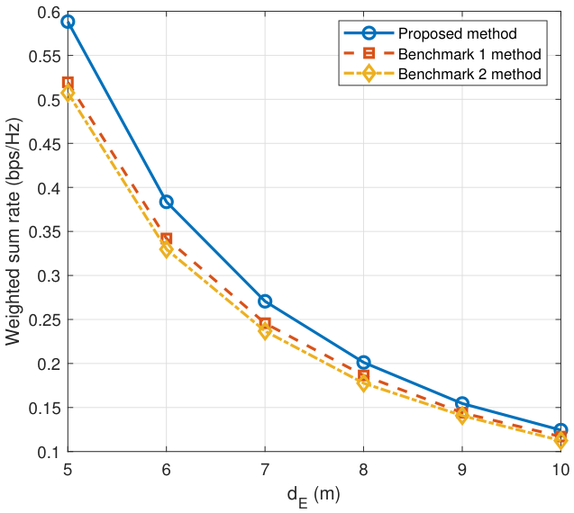
Figure 2 investigates the impact of the EN distance d E on the weighted sum rate performance, where d E varies from 5 to 10 m. As d E increases, the weighted sum rate of all three schemes decreases monotonically, because the EN-to-WDs energy transfer links become weaker and hence provide less harvested energy for both intra-pair message exchange and subsequent cooperative UL transmission. The proposed method consistently achieves the highest weighted sum rate over the whole range of d E . This is because it not only reuses the WPT signal to avoid extra local communication overhead, but also optimizes the EN-side energy transmission to improve energy efficiency. As a result, the proposed design better mitigates the performance loss caused by unfavorable EN-to-WDs energy transfer conditions.
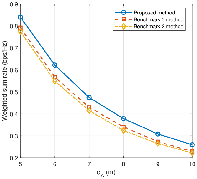
Figure 3 shows the weighted sum rate versus the AP distance d A . As expected, all three schemes suffer performance degradation when d A increases, since a larger WD-to-AP distance weakens the cooperative UL transmission. Nevertheless, the proposed method maintains a clear advantage over the two benchmark schemes throughout the whole range of d A . The reason is that the proposed design completes local message exchange by reusing the WPT signal, and thus avoids the extra time and harvested energy consumption required by active local transmission. Consequently, it leaves more resources for the cooperative UL stage and becomes more resilient to the degradation of the WD-to-AP links.
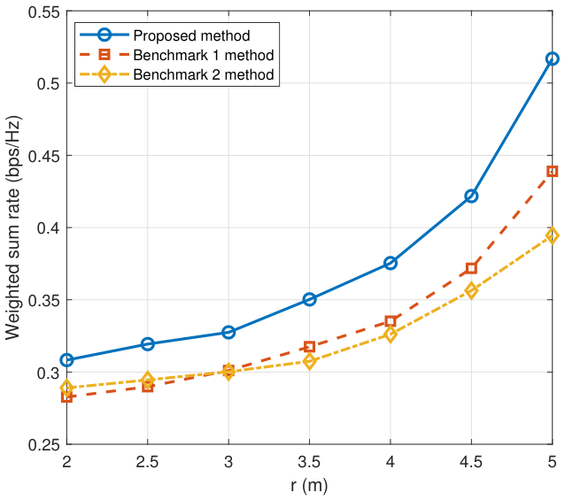
Figure 4 illustrates the impact of the user-region radius r on the weighted sum rate. As r increases, all three schemes achieve higher weighted sum rates, which indicates that a wider user distribution creates more favorable geometric conditions for transmission. A notable observation is that the Benchmark 1 method performs slightly worse than the Benchmark 2 method when the radius is small, i.e., r < 3 m. This suggests that, when the WDs are distributed in a compact region, the gain provided by pairwise cooperation is still limited, while the corresponding cooperation overhead cannot be fully compensated without EN-side beamforming optimization. As r becomes larger, the benefit of pairwise cooperation becomes more evident. In this case, the proposed method shows the largest improvement, since it reduces the local-exchange overhead through WPT signal reuse and further exploits the increased spatial diversity through optimized EN-side beamforming. On average, the proposed scheme improves the weighted sum rate by 11.65% and 14.65% compared with Benchmark 1 and Benchmark 2, respectively.
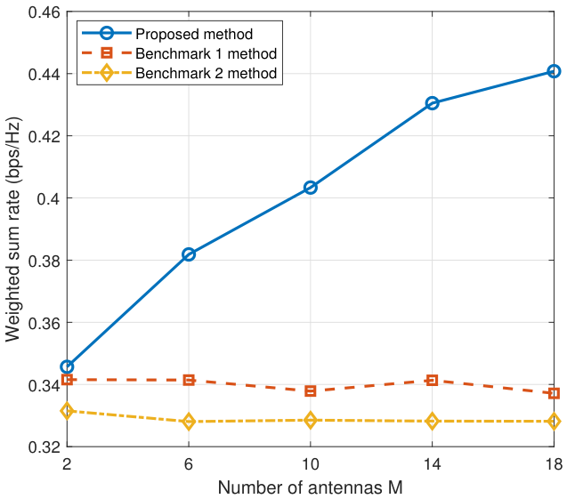
We then examine the effect of the number of EN antennas M in Figure 5. A clear observation is that the proposed method benefits significantly from increasing M, whereas the gains of the two benchmark schemes remain marginal. This result indicates that the performance gain from a larger antenna array cannot be fully exploited unless the EN-side transmission is properly optimized. In the proposed scheme, a larger M provides more spatial degrees of freedom for energy beamforming, so that the EN can deliver the WPT signal more efficiently to the paired WDs. As a result, the system obtains more usable energy for both intra-pair message exchange and cooperative UL transmission. By contrast, the Benchmark 1 method does not optimize the beamforming matrix, and the Benchmark 2 method further removes pairwise cooperation. Therefore, only the proposed design can effectively convert the increased number of EN antennas into a noticeable weighted sum rate gain.
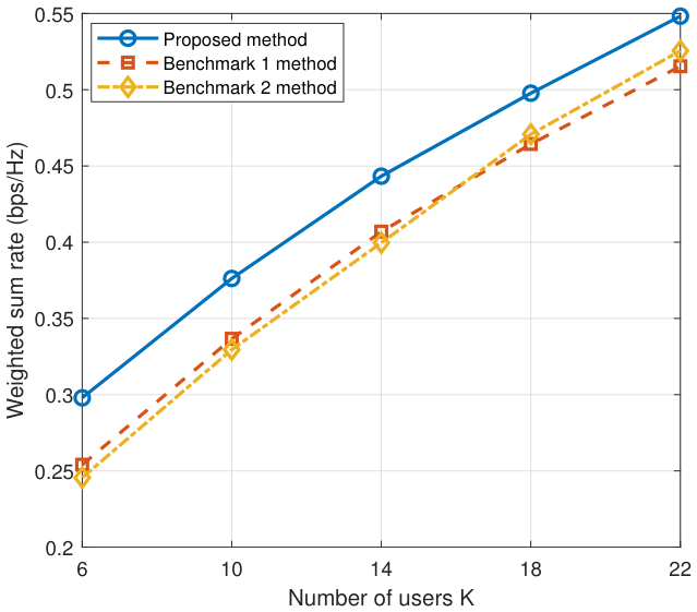
In Figure 6, we investigate the effect of the number of WDs K on the weighted sum rate performance, where K varies from 6 to 22. As K increases, the weighted sum rate of all three schemes grows accordingly, since more users create more transmission opportunities under the weighted sum rate criterion. The proposed method consistently achieves the best performance over the whole range of K, because it reduces the additional time and energy cost of cooperation through WPT signal reuse and further improves resource utilization by optimizing the EN-side beamforming. It is also worth noting that the Benchmark 1 method becomes slightly worse than the Benchmark 2 method when K is relatively large (around 16). This suggests that, without EN-side beamforming optimization, the gain brought by pairwise cooperation is gradually offset by the accumulated cooperation overhead as the number of user pairs increases. In a word, the result shows that the proposed scheme scales more effectively with the network size.
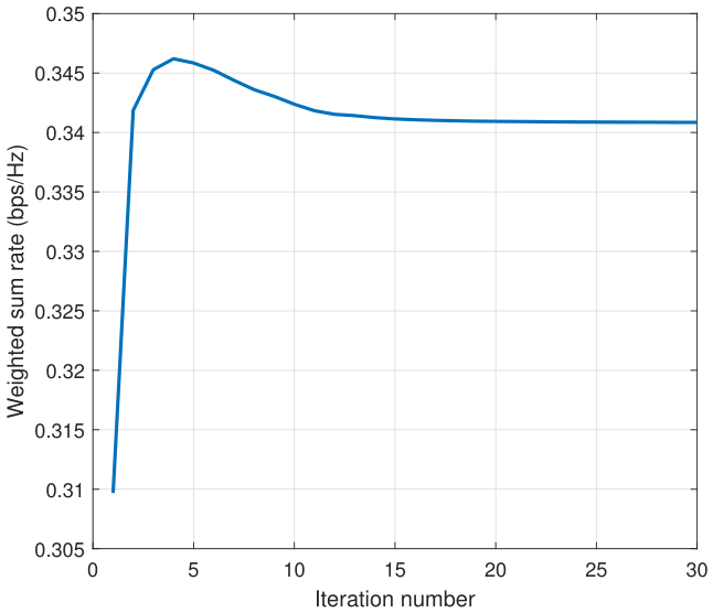
Finally, we illustrate the convergence behavior of the proposed AO algorithm in Figure 7. The weighted sum rate increases rapidly in the first several iterations and then gradually approaches a stable value, with near convergence achieved after about 13 iterations. This behavior is expected, since the alternating updates of the time-and-energy variables and the EN-side beamforming matrix can capture the dominant gain in the early stage, while the remaining improvement becomes increasingly limited as the algorithm proceeds. The result confirms that the proposed algorithm converges reliably and attains the final performance within a relatively small number of iterations.
Overall, the simulation results in Figure 2, Figure 3, Figure 4, Figure 5, Figure 6 and Figure 7 verify the effectiveness of the proposed backscatter-assisted pairwise cooperation scheme in improving the weighted sum rate of multi-user WPCNs. The performance gain mainly comes from reusing the WPT signal for intra-pair information exchange, which reduces the additional time and energy consumption required for local cooperation and preserves more resources for the subsequent cooperative uplink transmission. Moreover, the optimized EN-side energy beamforming further improves the efficiency of wireless energy delivery. As a result, the proposed scheme can consistently achieve superior performance under different network settings and more effectively exploit the available transmission time and harvested energy than the two benchmark methods.

6. Conclusions

In this paper, we investigated a multi-user WPCN with backscatter-assisted pairwise cooperation. Specifically, paired WDs reused the WPT signal to exchange their local messages through passive backscatter communication and then cooperatively transmitted their information to the AP in the uplink. Under this transmission framework, we formulated a weighted sum rate maximization problem by jointly optimizing the time allocation, the user transmit-power allocation, and the EN energy beamforming matrix. To solve the resulting non-convex problem, we developed an alternating-optimization algorithm, where the time-and-energy allocation subproblem was reformulated into an equivalent convex form and the energy beamforming matrix was updated through a semidefinite program. Numerical results showed that the proposed scheme achieved clear performance gains over the benchmark methods under various network settings. The gain mainly came from reusing the WPT signal for intra-pair information exchange, which reduced the additional time and energy consumption required for local cooperation and preserved more resources for the subsequent cooperative uplink transmission. Moreover, the optimized EN-side energy beamforming further improved the efficiency of wireless energy delivery. As a result, the proposed design provided an effective way to enhance the weighted sum rate performance in multi-user WPCNs.

Author Contributions

Conceptualization, Y.Z.; methodology, Y.Z.; software, Y.Z. and F.T.; validation, Y.Z. and Y.W.; formal analysis, Y.Z. and W.W.; investigation, F.T. and Y.W.; resources, W.W.; data curation, W.W.; writing—original draft preparation, Y.Z.; writing—review and editing, Y.Z.; visualization, W.W. and Y.W.; supervision, Y.Z. and Y.W.; project administration, Y.Z.; funding acquisition, Y.W. All authors have read and agreed to the published version of the manuscript.

Funding

This research was funded by the Scientific Research Project of Shenzhen Polytechnic University under Grants No. 6024310011K, 6024310031K, and 1055-6024210101K1, and in part by the Shenzhen Science and Technology Program under Grant RCBS20231211090733053.

Data Availability Statement

The data will be made available upon request.

Conflicts of Interest

The authors declare no conflicts of interest.

References

  1. Bi, S.; Zeng, Y.; Zhang, R. Wireless powered communication networks: An overview. IEEE Commun. Mag. 2016, 23, 10–18. [Google Scholar] [CrossRef]
  2. Han, K.; Huang, K. Wirelessly powered backscatter communication networks: Modeling, coverage, and capacity. IEEE Trans. Commun. 2017, 16, 2548–2561. [Google Scholar] [CrossRef]
  3. Lu, X.; Wang, P.; Niyato, D.; Kim, D.I.; Han, Z. Wireless networks with RF energy harvesting: A contemporary survey. IEEE Commun. Surv. Tuts. 2015, 17, 757–789. [Google Scholar] [CrossRef]
  4. Bi, S.; Zhang, Y.; Zhang, R. Distributed scheduling in wireless powered communication network: Protocol design and performance analysis. In Proceedings of the 2017 15th International Symposium on Modeling and Optimization in Mobile, Ad Hoc, and Wireless Networks (WiOpt), Paris, France, 15–19 May 2017. [Google Scholar]
  5. Ju, H.; Zhang, R. Throughput maximization in wireless powered communication networks. IEEE Trans. Wirel. Commun. 2014, 13, 418–428. [Google Scholar] [CrossRef]
  6. Yuan, L.; Bi, S.; Zhang, S.; Lin, X.; Wang, H. Multi-antenna enabled cluster-based cooperation in wireless powered communication networks. IEEE Access. 2017, 5, 13941–13956. [Google Scholar] [CrossRef]
  7. Zheng, Y.; Bi, S.; Zhang, Y.; Lin, X.; Wang, H. Joint beamforming and power control for throughput maximization in IRS-assisted MISO WPCNs. IEEE Internet Things J. 2021, 8, 8399–8410. [Google Scholar] [CrossRef]
  8. Zhu, G.; Dong, J.; Grazian, F.; Bauer, P. A Hybrid Modulation Scheme for Efficiency Optimization and Ripple Reduction in Secondary-Side Controlled Wireless Power Transfer Systems. IEEE Trans. Transp. Electrif. 2025, 11, 6840–6853. [Google Scholar] [CrossRef]
  9. Ju, H.; Zhang, R. User cooperation in wireless powered communication networks. In 2014 IEEE Global Communications Conference, Austin, TX, USA, 8–12 December 2014; IEEE: New York, NY, USA, 2014; pp. 1430–1435. [Google Scholar]
  10. Zhong, M.; Bi, S.; Lin, X. User cooperation for enhanced throughput fairness in wireless powered communication networks. Wirel. Netw. 2017, 23, 1315–1330. [Google Scholar] [CrossRef]
  11. Gautam, S.; Ubaidulla, P. Relay selection and transceiver design for joint wireless information and energy transfer in cooperative networks. In Proceedings of the 2017 IEEE 85th Vehicular Technology Conference (VTC Spring), Sydney, NSW, Australia, 4–7 June 2017; IEEE: New York, NY, USA, 2017; pp. 1–5. [Google Scholar]
  12. Yuan, L.; Bi, S.; Lin, X.; Wang, H. Throughput fairness optimization for cluster-based collaboration. IEEE Syst. J. 2024, 18, 551–559. [Google Scholar] [CrossRef]
  13. Van, H.N.; Hoang, D.T.; Lu, X.; Niyato, D.; Wang, P.; Kim, D.I. Ambient backscatter communications: A contemporary survey. IEEE Commun. Surv. Tuts. 2018, 20, 2889–2922. [Google Scholar]
  14. Hoang, D.T.; Niyato, D.; Wang, P.; Kim, D.I.; Han, Z. Ambient backscatter: A new approach to improve network performance for RF-powered cognitive radio networks. IEEE Trans. Commun. 2017, 65, 3659–3674. [Google Scholar] [CrossRef]
  15. Wang, G.; Gao, F.; Fan, R.; Tellambura, C. Ambient backscatter communication systems: Detection and performance analysis. IEEE Trans. Commun. 2016, 64, 4836–4846. [Google Scholar] [CrossRef]
  16. Darsena, D.; Gelli, G.; Verde, F. Modeling and performance analysis of wireless networks with ambient backscatter devices. IEEE Trans. Commun. 2017, 65, 1797–1814. [Google Scholar] [CrossRef]
  17. Qian, J.; Parks, A.N.; Smith, J.R.; Gao, F. IoT communications with M-PSK modulated ambient backscatter: Algorithm, analysis, and implementation. IEEE Internet Things J. 2018, 6, 844–855. [Google Scholar] [CrossRef]
  18. Qian, J.; Zhu, Y.; He, C.; Gao, F.; Jin, S. Achievable rate and capacity analysis for ambient backscatter communications. IEEE Trans. Commun. 2019, 67, 6299–6310. [Google Scholar] [CrossRef]
  19. Kim, S.H.; Kim, D.I. Hybrid backscatter communication for wireless-powered heterogeneous networks. IEEE Trans. Commun. 2017, 16, 6557–6570. [Google Scholar] [CrossRef]
  20. Gong, S.; Huang, X.; Xu, J.; Liu, W.; Wang, P.; Niyato, D. Backscatter relay communications powered by wireless energy beamforming. IEEE Trans. Commun. 2018, 66, 3187–3200. [Google Scholar] [CrossRef]
  21. Munir, D.; Mughal, D.M.; Manhboob, T.; Chung, M.Y. Relay selection scheme for cooperative backscatter communications networks. In Computational Science and Its Applications—ICCSA 2018; Springer: Cham, Switzerland, 2018; pp. 558–569. [Google Scholar]
  22. Lyu, B.; Hoang, D.T.; Yang, Z. User cooperation in wireless-powered backscatter communication networks. IEEE Wirel. Commun. Lett. 2019, 8, 632–635. [Google Scholar] [CrossRef]
  23. Zheng, Y.; Bi, S.; Lin, X. Reusing wireless power transfer for backscatter-assisted relaying in WPCNs. Comput. Netw. 2020, 13, 107277. [Google Scholar] [CrossRef]
  24. He, Y.; Wu, X.; He, Z.; Guizani, M. Energy efficiency maximization of backscatter-assisted wireless-powered MEC with user cooperation. IEEE Trans. Mob. Comput. 2024, 23, 1878–1887. [Google Scholar] [CrossRef]
  25. Gujral, S.; Sarma, S. Multi-backscatter assisted wireless powered communication network for green IoT. IEEE Internet Things J. 2025, 12, 39862–39876. [Google Scholar] [CrossRef]
  26. Kang, J.M.; Kim, I.M.; Kim, D.I. Joint Tx power allocation and Rx power splitting for SWIPT system with multiple nonlinear energy harvesting circuit. IEEE Wirel. Commun. Lett. 2019, 8, 53–56. [Google Scholar] [CrossRef]
  27. Ma, G.; Xu, J.; Zeng, Y.; Moghadam, M. A generic receiver architecture for MIMO wireless power transfer with non-linear energy harvesting. IEEE Signal Proc. Lett. 2019, 26, 312–316. [Google Scholar] [CrossRef]
Figure 1. The schematic illustration of the system model and transmission protocol for the proposed cooperation scheme.
Electronics 15 02227 g001
Figure 2. Weighted sum rate performance versus the distance between the EN and WDs.
Electronics 15 02227 g002
Figure 3. Weighted sum rate performance versus the distance between the AP and WDs.
Electronics 15 02227 g003
Figure 4. Weighted sum rate performance versus the user-region radius.
Electronics 15 02227 g004
Figure 5. Weighted sum rate performance versus the number of EN antennas.
Electronics 15 02227 g005
Figure 6. Weighted sum rate performance versus the number of WDs K.
Electronics 15 02227 g006
Figure 7. The convergence behavior of the proposed AO algorithm.
Electronics 15 02227 g007
Disclaimer/Publisher’s Note: The statements, opinions and data contained in all publications are solely those of the individual author(s) and contributor(s) and not of MDPI and/or the editor(s). MDPI and/or the editor(s) disclaim responsibility for any injury to people or property resulting from any ideas, methods, instructions or products referred to in the content.