


Abstract
This paper presents a unified dynamic-modeling and error-analysis framework for an FTR (force-to-rebalanced)-operated MEMS ring gyroscope. Starting from an equivalent mass-point representation of the ring resonator, a dynamic model including stiffness and damping errors is first established. Principle-related inertial-acceleration errors and structural errors are then analyzed within the same framework. The results show that, under practical rate-measurement conditions, inertial-acceleration errors have negligible effects on both the drive and sense modes. In contrast, structural errors, including modal-frequency perturbation, damping-decay-time mismatch, mass-distribution mismatch, and electrode angular misalignment, impair drive-mode amplitude control and frequency tracking, introduce in-phase bias components into the sense-mode output, and produce quadrature signals through frequency coupling. The analysis further indicates that electrostatic mode matching should be implemented in two steps: quadrature-stiffness correction followed by modal-frequency tuning. The proposed model provides a concise and physically transparent basis for resonator design, parameter identification, and control compensation in high-performance MEMS ring gyroscopes.
1. Introduction
MEMS gyroscopes have become indispensable inertial sensors in navigation, motion control, robotics, and aerospace applications because of their small size, low power consumption, low cost, and compatibility with batch fabrication [1,2,3,4,5]. Among them, Coriolis vibratory gyroscopes (CVGs) sense angular motion through the coupling between orthogonal vibration modes and have evolved into several representative operation schemes with different trade-offs in accuracy, bandwidth, dynamic range, and implementation complexity [1,4,6]. Recent review studies generally classify MEMS gyroscope operation into amplitude-modulated (AM) [7], whole-angle (WA) [8], and frequency-modulated (FM) [9] modes, highlighting that the choice of operation mode strongly affects both achievable performance and dominant error mechanisms.
Within the CVG family, MEMS ring gyroscopes are particularly attractive for high-performance applications because their axisymmetric resonators provide high mechanical symmetry, strong shock tolerance, and relatively low temperature sensitivity [10,11,12]. Owing to these advantages, ring-based and ring-derived resonators have been widely investigated as promising candidates for precision MEMS gyroscopes. For rate-output applications, the FTR mode has been extensively adopted because it constrains the sense-mode motion through closed-loop feedback, thereby improving rate-measurement accuracy and stability [13,14]. At the same time, the literature also reveals a clear divergence in operational philosophy: WA [15] and FM [16] modes are often pursued for direct angle output or broader dynamic characteristics, whereas FTR-based AM operation remains highly competitive when stable closed-loop rate measurement is the primary objective [17].
Accurate dynamic modeling is fundamental to the structural design, closed-loop control, parameter identification, and performance evaluation of MEMS ring gyroscopes operated in FTR mode. Existing studies have investigated the mechanisms of frequency splitting in ring resonators [18,19], the correction of structural imperfections [20,21], and the vibration characteristics under non-ideal factors such as electrostatic loading [10,22], geometric irregularity [19,23], and material anisotropy [23,24,25], thereby establishing an important foundation for understanding the non-ideal dynamics of MEMS ring gyroscopes. Meanwhile, FTR-related studies have shown that mode mistuning [26], stiffness perturbation [27], and damping mismatch [28] can significantly affect closed-loop decoupling, zero-rate output, and scale-factor linearity, making the coupling between resonator dynamics and control architecture a critical issue in high-performance rate measurement. In particular, for MEMS ring gyroscopes employing FTR control, the sense mode is strongly constrained by feedback, and the actual output characteristics are influenced not only by the ideal Coriolis term, but also by additional inertial terms, modal-parameter deviations, mass-distribution mismatch, and electrode-transduction errors. In addition to resonator-level modeling, closed-loop control and interface electronics are also essential for translating the mechanical dynamics of MEMS gyroscopes into stable rate outputs. For example, Gill et al. presented a detailed analysis of the dynamic behavior of a MEMS vibrating internal ring gyroscope, providing useful insights into the vibration characteristics and mode behavior of ring-type resonators [29]. These considerations motivate the present work to link structural-error modeling with FTR closed-loop rate measurement and compensation.
From the perspective of error mechanisms, dynamic modeling in FTR operation must therefore address at least two issues. The first is how the inertial-acceleration terms inherent in the sensing principle affect the system response, namely, how principle errors should be characterized. The second is how structural and fabrication non-idealities, including modal-frequency errors, damping-decay errors, mass-distribution mismatch, and electrode angular misalignment, are coupled into the governing equations, namely, how structural errors should be modeled. However, many existing models are still established on the basis of ideally axisymmetric resonators or consider only a single class of error factor, rather than providing a unified dynamic framework that simultaneously addresses both principle errors and structural errors and links them explicitly to measurable modal parameters. Especially for FTR-operated MEMS ring gyroscopes, how to incorporate both principle errors and structural errors into a unified model and further clarify their influence on closed-loop rate-measurement performance remains an open issue.
To address this issue, this paper establishes a dynamic model for a MEMS ring gyroscope operated in FTR mode and develops a corresponding error-analysis framework from the perspectives of both principle errors and structural errors. The principle-error analysis clarifies the inertial-acceleration terms embedded in the governing equations and evaluates their influence under practical rate-operation conditions. The structural-error analysis further incorporates modal-frequency perturbation, damping-decay-time mismatch, mass-distribution mismatch, and electrode angular misalignment into a unified model expressed in terms of measurable modal parameters. On this basis, the dominant error mechanisms relevant to FTR rate measurement are identified, providing a clearer physical foundation for subsequent design optimization, parameter identification, and control compensation of MEMS ring gyroscopes.
It should be noted that the principle-related inertial-acceleration errors considered in this paper are not expected to dominate the output error under practical rate-measurement conditions. In the FTR-operated ring gyroscope, the sense modal displacement is suppressed by the rebalance loop, so several inertial terms associated with sense-mode motion are intrinsically weakened. In addition, the input angular rate is generally much lower than the modal resonant frequency of the vibrating ring resonator. As a result, the centripetal and coupling-induced inertial-acceleration terms, which scale with the square or product of the input angular-rate components, are much smaller than the Coriolis term proportional to the product of the input angular rate and the drive-mode vibration velocity. This scale separation provides the physical basis for treating inertial-acceleration errors as negligible under practical rate-sensing conditions, while structural errors remain the dominant error sources affecting the FTR output.
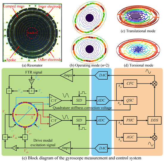
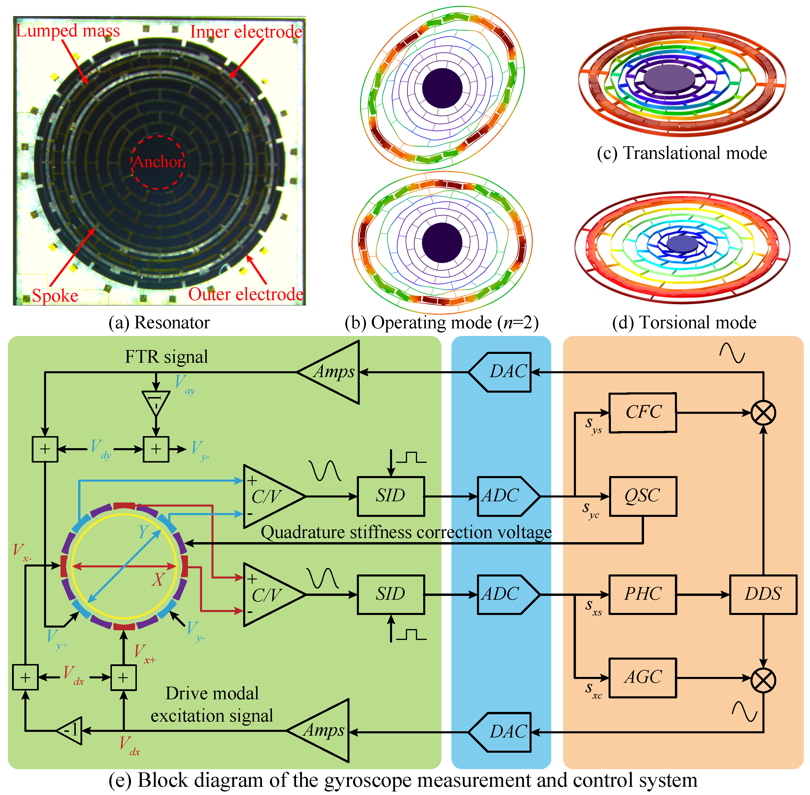
A multi-ring resonator with a centrally supported single-anchor configuration is adopted in this paper. The resonator is equipped with inner and outer dual-layer electrodes, while lumped mass blocks are suspended from the inner ring structure. This configuration enables fully differential actuation and sensing, thereby improving the excitation/sensing efficiency and the signal-to-noise ratio of the gyroscope output. Meanwhile, the suspended lumped masses increase the effective Coriolis mass of the resonator, reduce thermoelastic damping, and mitigate structural asymmetry caused by fabrication errors. Figure 1a–d presents a photograph of the multi-ring resonator together with the simulated results of several vibration modes. The resonator consists of eight concentrically nested rings and a central anchor, with adjacent rings, as well as the rings and the anchor, interconnected by interleaved spokes at an angular interval of 22.5°. Arc-shaped electrodes are arranged on both the inner and outer sides of the outermost ring at prescribed angular positions with a fixed arc length, forming the fully differential actuation and sensing electrodes. In addition, lumped mass blocks are suspended from the second and third rings, counted from the outside inward, to further enhance the overall performance of the resonator. The structural design parameters of the proposed multi-ring resonator are listed in Table 1 for the subsequent simulation analysis.
Figure 1.
MEMS ring resonator and its gyroscope measurement and control system: (a) resonator; (b) operating mode; (c) translational mode; (d) torsional mode; (e) block diagram of the gyroscope measurement and control system.
Table 1.
Structural design parameters of the proposed multi-ring resonator.
A rate-mode ring gyroscope has two operating modes, namely the drive mode (X) and the sense mode (Y). The drive mode maintains a stable-amplitude harmonic oscillation, whereas the sense mode is used to extract the input angular-rate information and quadrature-error information in real time. Figure 1e shows the block diagram of the FTR measurement and control system, which consists of the packaged ring-gyroscope device and the associated control electronics. The control electronics mainly comprise an electromechanical interface analog circuit, a mixed-signal circuit, and a digital circuit. The electromechanical interface analog circuit includes a capacitance-to-voltage (C/V) conversion circuit, a synchronous integral demodulation (SID) circuit, and differential actuation/rebalance circuits for resonator excitation and signal detection [27]. The digital circuit is implemented on an FPGA and is responsible for the closed-loop control of the drive and sense modes. The mixed-signal circuit, composed of ADC and DAC modules, provides the interface between the analog and digital circuits. After the capacitance variations in the drive and sense modes are converted into voltage signals through the C/V circuit, their phase and amplitude information are extracted by SID. For the drive mode, an automatic gain controller (AGC) is used to sustain stable oscillation, while a phase controller (PHC) tracks the resonant frequency in real time. For the sense mode, a quadrature-stiffness controller (QSC) and a Coriolis force controller (CFC) are employed to suppress quadrature coupling and input-rate-induced vibration, respectively. The output of the CFC represents the input angular rate, whereas the output of the QSC represents the quadrature error. The following analysis is based on this control architecture.
2. Error-Based Dynamic Modeling
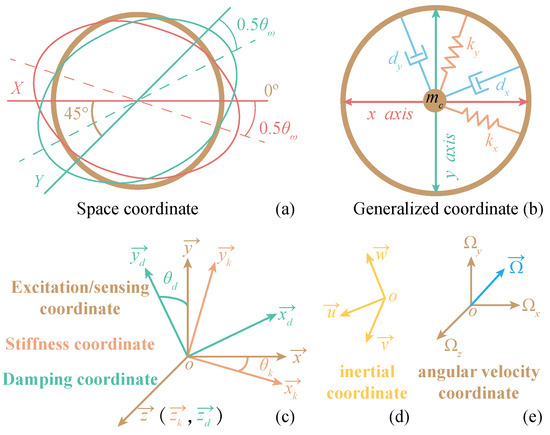
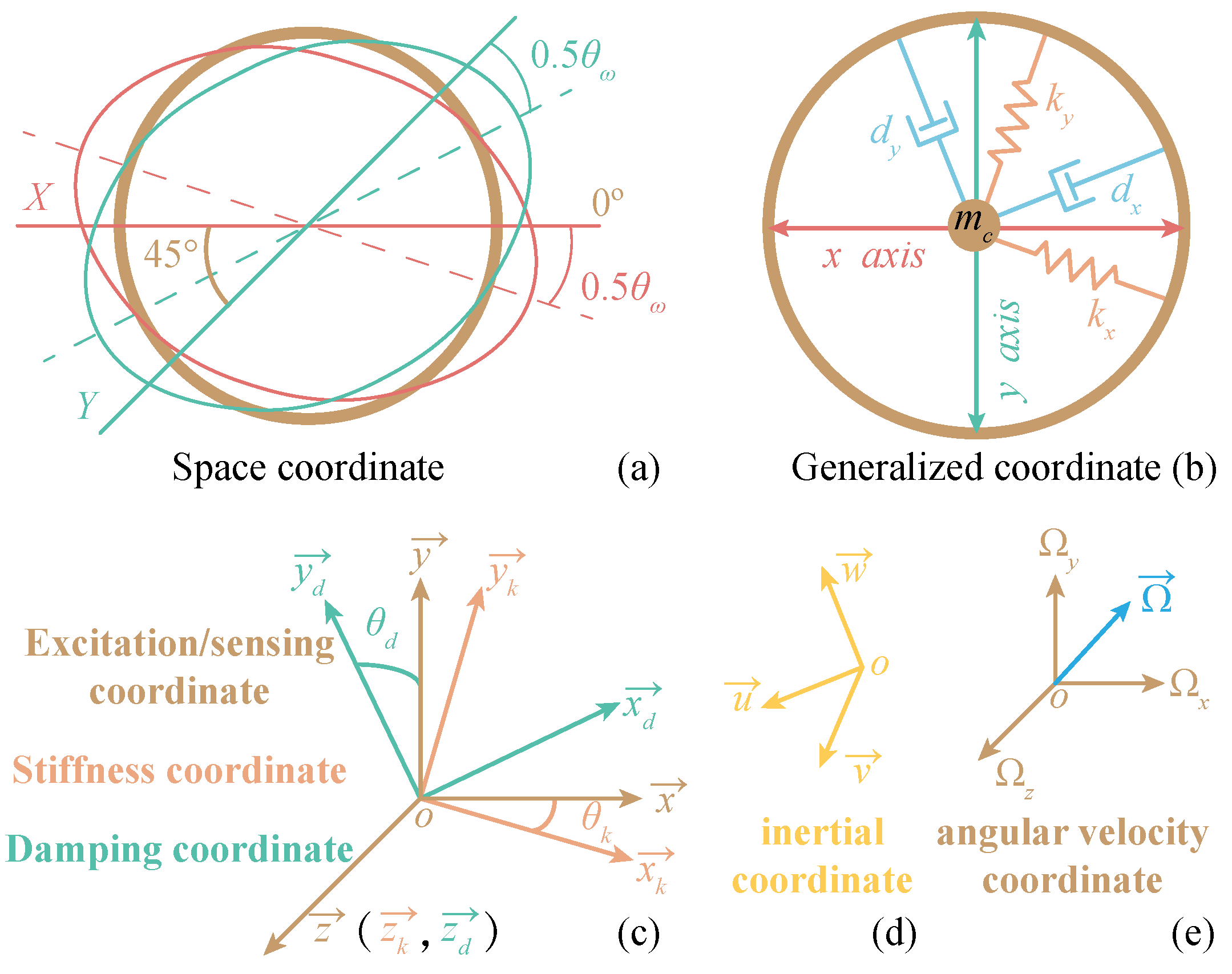
To simplify the derivation, the ring-resonator dynamics are first formulated by considering only stiffness and damping errors. For the wineglass mode, the spatial coordinate system is defined by the X- and Y-axes, which are separated by 45°. Because of unavoidable fabrication errors, the antinodes of the actual mode shape do not exactly align with the X- and Y-axes, so the principal frequency axis is rotated by , as shown in Figure 2a.
Figure 2.
Motion coordinate systems of the ring resonator: (a) spatial coordinate; (b) generalized coordinate; (c) drive/sense coordinate, stiffness coordinate, and damping coordinate; (d) inertial coordinate; and (e) angular velocity coordinate.
The resonator motion is then mapped to generalized coordinates, in which the ring resonator is represented by an equivalent point mass together with the associated stiffness and damping axes. As shown in Figure 2b, the stiffness coefficients along the two axes are denoted by and , and the damping coefficients by and , with and in the presence of structural imperfections. The generalized coordinates x and y describe the displacement of the equivalent point mass, but do not necessarily coincide with the X- and Y-axes in the spatial coordinate system.
The generalized coordinate system is further taken to coincide with the drive/sense coordinate system, while the stiffness and damping coordinate systems are denoted by and , respectively, as shown in Figure 2c. The z-axes of these coordinate systems coincide and are perpendicular to the corresponding in-plane axes. The angles between and and between and are denoted by and , respectively. Accordingly, the transformation from the stiffness coordinate system to the drive/sense coordinate system is written as
The transformation from the damping coordinate to the drive/sense coordinate system is given by:
According to the sensing principle of the gyroscope, the three coordinate systems shown in Figure 2c remain fixed to the gyroscope carrier and rotate with it relative to the inertial coordinate system at an angular velocity . The angular velocity vector can therefore be decomposed in the drive/sense and inertial coordinate systems as
where , , and denote the components of in the drive/sense coordinate system, whereas , , and denote those in the inertial coordinate system. For simplicity, axis-dependent angular gains are not introduced at this stage.
As the drive/sense coordinate system rotates with angular velocity , the velocity and acceleration of the endpoint can be written in vector-product form as
Because the ring electrodes can only actuate and sense along the axes of the drive/sense coordinate system, the position vector of the equivalent mass point is decomposed in this coordinate system. Based on Equations (4) and (5), the displacement, velocity, and acceleration of the equivalent mass point in the inertial coordinate system are obtained as
where denotes the position vector of the equivalent mass point in the drive/sense coordinate system, and denotes the linear acceleration. The variables x and y denote the displacements of the equivalent mass point along the - and -axes, respectively.
The forces acting on the equivalent mass point of the ring resonator can be classified into five categories: gravity, normal support force, elastic restoring force, damping force, and electrostatic force. As the equivalent mass point is constrained to vibrate in the plane, gravity is balanced by the normal support force. The resultant force acting on the equivalent mass point is therefore given by
where is the driving force acting on the equivalent mass point, and denote the displacement components in the stiffness coordinate system, and and denote the velocity components in the damping coordinate system. The relationships among , , and are therefore written as
Applying Newton’s second law to the equivalent mass point of the ring resonator yields:
Based on the above dynamic analysis, and taking into account the angular velocity gain and centripetal-force gain along each axis, Equation (11) can be obtained by substituting Equation (6) into the left-hand side of Equation (10), and Equations (1), (2), (8), and (9) into its right-hand side
where
, , , and are the centripetal-force gains corresponding to the x-axis, y-axis, inter-axis coupling, and z-axis, respectively. The parameter is defined as the ratio of the rotational angular velocity of the gyroscope carrier to the sensitive angular velocity of the resonator, i.e., the angular gain. Moreover, , , , and are treated as dimensionless error perturbation terms.
Equation (11) describes the dynamics of the Coriolis vibratory ring gyroscope based on the equivalent mass-point model, with stiffness and damping errors taken into consideration. For the ring resonator, stiffness and damping are discretely distributed structural properties that cannot be directly measured in practice. However, the corresponding modal parameters, namely modal frequency and damping decay time, are measurable. Moreover, the ring resonator is affected by mass-distribution mismatch and electrode angular misalignment. Accordingly, the following section establishes a dynamic equation of the ring gyroscope that incorporates errors in modal frequency and damping decay time, while also accounting for mass-distribution mismatch and electrode angular misalignment.
3. Analysis of Errors Caused by Operating Principles
The principle errors of a Coriolis vibratory gyroscope are defined as those associated with the sensing principle itself, rather than with non-ideal factors introduced during fabrication, assembly, testing, control, or operation. It can be seen from Equation (11) that these principle errors in the dynamic equation are mainly embodied in the matrix . This category of errors is referred to as inertial-acceleration errors, as summarized in Table 2.
Table 2.
Classification of inertial-acceleration errors associated with principle errors.
3.1. Effects of Inertial-Acceleration Errors on the Drive Mode
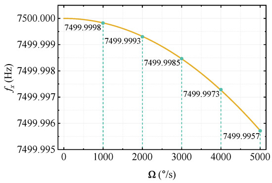
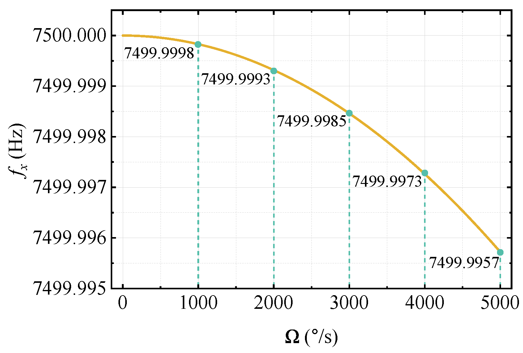
Since the sense mode is operated under force-to-rebalance control, its displacement (y) and velocity () can be approximately regarded as zero. Accordingly, the transport tangential inertial-acceleration term () and the coupling-induced inertial-acceleration term () in the drive-mode equation can be neglected. In contrast, the transport centripetal inertial-acceleration term () modifies the effective stiffness of the X mode and thus causes a shift in its resonant frequency. To simplify the analysis without weakening the representation of inertial-acceleration effects, the input angular velocities about different axes are not distinguished, and the relevant centripetal-gain parameters are, without loss of generality, equivalently taken as . Under this assumption, this term can be uniformly written as . Figure 3 shows the effect of the ratio between the input angular velocity and the modal frequency on the resonant frequency of the X mode. When the input angular velocities about the Y and Z axes are both (), changes by only . Therefore, the above three types of inertial-acceleration errors have a negligible effect on the drive mode of a ring gyroscope operating under force-to-rebalance control.
Figure 3.
Effect of angular velocity on the drive modal frequency under inertial-acceleration errors.
3.2. Effects of Inertial-Acceleration Errors on the Sense Mode
The transport centripetal inertial-acceleration term () likewise produces a stiffness-softening effect on the Y mode. According to the analysis in Section 3.1, the influence of this type of error on the sense modal frequency can also be neglected. In contrast, the transport tangential inertial-acceleration term () and the coupling-induced inertial-acceleration term () can be equivalently regarded as external excitation forces acting on the Y mode. The sense modal vibration signals induced by these two types of inertial acceleration are in phase with the quadrature output signal. Therefore, the corresponding error outputs can be separated from the rate information through IQ decomposition, thereby preventing interference with rate measurement.
Furthermore, based on the simulation parameters listed in Table 3, and using the same gain-equivalence treatment as that adopted in Section 3.1, the Coriolis acceleration, equivalent quadrature acceleration, transport centripetal inertial acceleration, and coupling-induced inertial acceleration in the sense mode are given by:
Table 3.
Simulation parameters for inertial-acceleration error analysis.
According to the above numerical results, even when the input angular velocity reaches , the equivalent quadrature acceleration remains one and two orders of magnitude higher than the transport centripetal inertial acceleration and the coupling-induced inertial acceleration, respectively. Considering the practical operating range of rate-mode MEMS ring gyroscopes, the influence of inertial-acceleration errors on the sense mode can likewise be neglected.
4. Analysis of Errors Caused by Structural Errors
As shown by the analysis in Section 3, the effect of principle errors on rate measurement in the FTR-operated ring gyroscope can be neglected. Accordingly, the matrix is omitted in the subsequent structural-error analysis. Equation (11) already includes the stiffness-coupling and damping-coupling errors. Building on this model, the effects of mass-distribution mismatch and drive/sense-electrode angular misalignment on FTR rate measurement are further investigated.
4.1. Mass-Distribution Mismatch
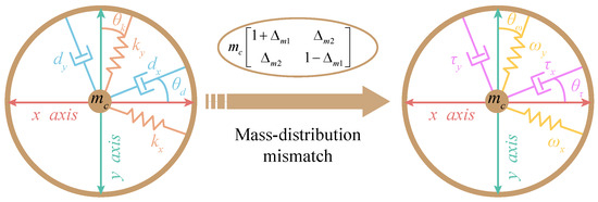
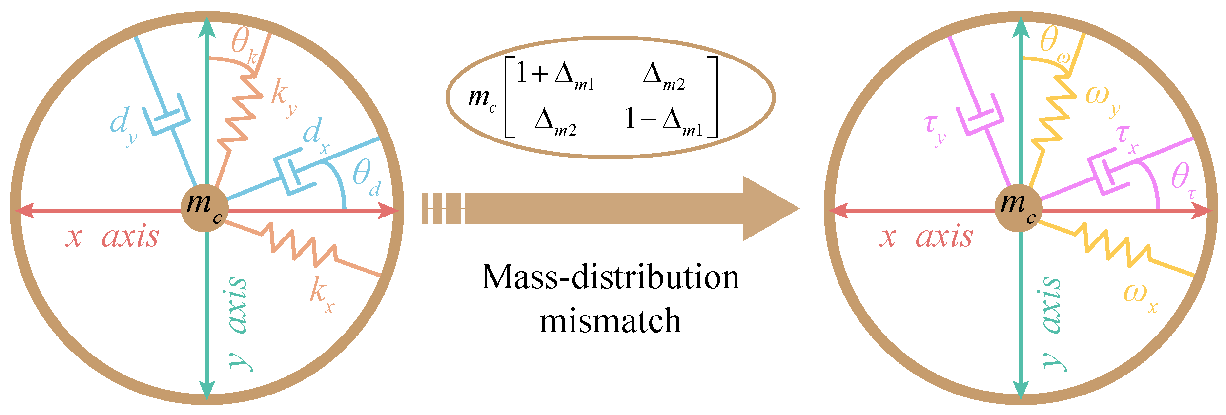
Equation (11) is established based on the equivalent mass-point model. However, fabrication and assembly errors in the ring resonator may cause the Coriolis masses associated with the X and Y modes to become unequal and may also introduce mass coupling, such that the mass matrix of the resonator is no longer a scalar matrix. When mass-distribution mismatch is taken into account, the mass matrix of the resonator can be written as
where and are dimensionless mass-perturbation terms.
Since the principle-related inertial-acceleration terms have been shown to be negligible under practical rate-sensing conditions, the matrix in Equation (11) is omitted in the following structural-error analysis. Replacing in Equation (11) with , the original dynamic equation can be rewritten as
where
According to dimensional analysis, Equations (28) and (29) represent the damping-decay-time matrix and the modal-frequency matrix, respectively. Since neither of these two matrices remains a scalar matrix, the damping decay times and resonant frequencies of the two operating modes of the ring gyroscope are no longer identical, and both damping-decay-time coupling and modal-frequency coupling arise accordingly. Specifically, damping-decay-time mismatch is jointly induced by mass-distribution mismatch and damping errors, whereas modal-frequency mismatch is jointly determined by mass-distribution mismatch and stiffness errors. Based on the above two matrices, the damping-decay-time axes and modal-frequency axes of the ring resonator can be further established, and the corresponding orientation angles can be determined from the eigenvectors of the matrices.
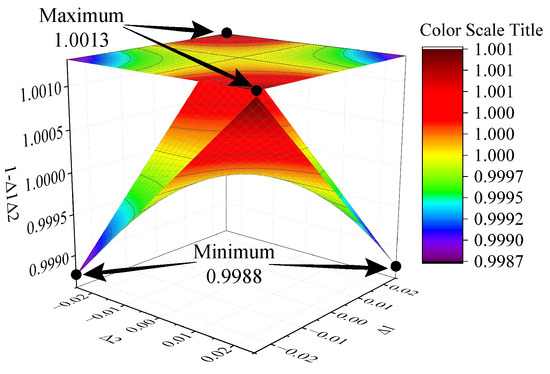
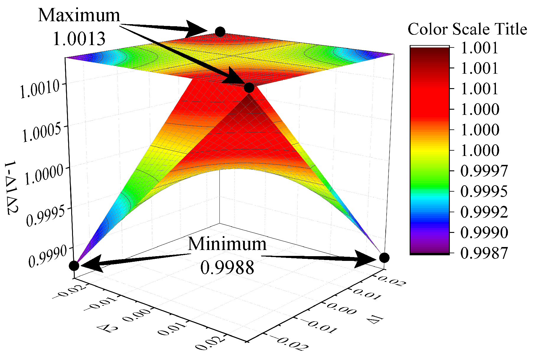
In general, , , , , , and are sufficiently small to be treated as perturbation terms. In the present analysis, these error terms are assumed to vary within , corresponding to an approximate variation of Hz with respect to the modal resonant frequency of 7500 Hz. As shown in Figure 4, the deviation of the second-order terms from unity is always confined within , which is only about of the first-order perturbation terms. Accordingly, the contribution of the second-order terms to the damping-decay-time matrix and the modal-frequency matrix is neglected in the following derivation.
Figure 4.
Variation trend of the second-order error terms.
By neglecting the second-order small terms, the eigenvalues and corresponding eigenvectors of Equations (28) and (29) can be further derived and analyzed. First, Equation (28) can be approximately simplified as
where
The eigenvalues of the matrix in Equation (30) and their corresponding eigenvectors are then obtained as
The above eigenvalues characterize the equivalent time constants of the ring resonator along the damping-decay-time axes, whereas the directions determined by the corresponding eigenvectors define the orientation of these axes, which can be expressed as
where can be regarded as the orientation angle of the damping-decay-time axes in the spatial coordinate system.
The damping-decay-time axes {} and the modal principal axes {} can be regarded as two different sets of basis vectors in a two-dimensional space. According to the coordinate transformation between different bases, together with the two-dimensional rotation matrix, can be reconstructed to yield a new damping-decay-time matrix:
where
In the matrix , and denote the damping decay times of the ring resonator along the two modal principal axes that can be observed through the sensing electrodes, while characterizes the damping coupling between the two operating modes. It follows from Equation (37) that the damping decay times along the modal principal axes are generally different, and that damping-coupling errors exist between the modes. Since the damping decay time is proportional to the quality factor, a higher quality factor of the ring resonator leads to a smaller damping-coupling error between the two modes.
Similar to the analysis of the damping-decay-time matrix, by neglecting the second-order small terms, can be further simplified as
where
Accordingly, the eigenvalues of the matrix in Equation (41) and their corresponding eigenvectors can be expressed as
Following the same procedure used for the damping-decay-time matrix, the coefficients along the modal-frequency axes and their orientation angle can be further obtained from the above eigenvalues and eigenvectors as
where can be regarded as the orientation angle of the frequency principal axes in the spatial coordinate system.
The modal-frequency principal axes {} and the modal principal axes {} can likewise be regarded as two different sets of basis vectors in a two-dimensional space. According to the coordinate transformation between different bases, together with the two-dimensional rotation matrix, can be reconstructed to yield a new modal-frequency matrix
where
In the matrix , and denote the modal frequencies along the two modal principal axes that can be observed through the sensing electrodes, while characterizes the frequency coupling between the two operating modes. It follows from Equation (48) that the modal frequencies along the modal principal axes are generally different, and that frequency-coupling errors exist between the two modes.
Based on the above analysis, a motion model of the ring resonator that simultaneously accounts for stiffness mismatch, damping mismatch, and mass-distribution mismatch can be established, as shown in Figure 5. This model includes the damping-decay-time axes {} and the modal-frequency axes {}, with each pair of axes being mutually orthogonal and oriented by the angles and , respectively. It can thus be seen that the dynamic equation of the ring gyroscope established in terms of measurable modal parameters, namely damping decay time and modal frequency, provides a more intuitive description of how structural errors affect the system dynamics and offers a clear basis for the analysis of practical sensing and control systems.
Figure 5.
Dynamic model of the ring resonator with damping mismatch, stiffness mismatch, and mass-distribution mismatch.
4.2. Electrode Angular Misalignment
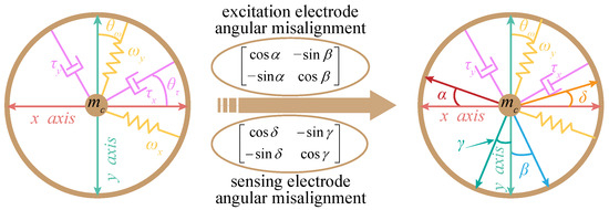
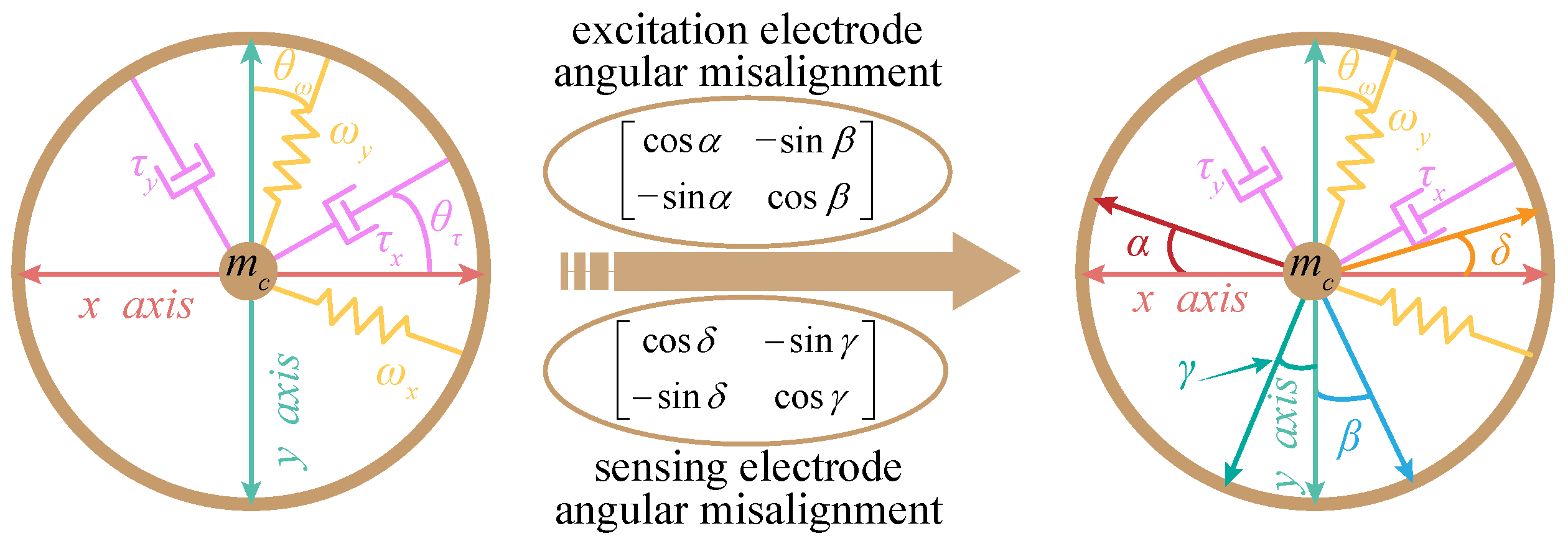
Based on the motion model shown in Figure 5, the angular misalignment between the modal drive/sense electrodes and the modal principal axes is further taken into account without loss of generality. The resulting resonator model is shown in Figure 6.
Figure 6.
Dynamic model of the ring resonator with damping mismatch, stiffness mismatch, mass-distribution mismatch, and electrode angular misalignment.
Here, is defined as the equivalent acceleration vector generated by the electrode actuation forces in the modal coordinate system, where and denote the acceleration components along the drive and sense modal axes, respectively. The subscript e indicates that this acceleration vector is associated with the electrode-force actuation path. Since , and can be treated as small quantities. By neglecting the second-order small terms, can be approximately expressed as
Equation (52) indicates that mass-distribution mismatch and drive-electrode angular misalignment jointly cause the electrode-force-to-acceleration mapping to deviate from an ideal diagonal form, thereby introducing force-mismatch errors. As a result, the actuation force of the drive mode is coupled into the sense mode and excites sense-mode vibration. Likewise, the rebalance force of the sense mode is coupled back into the drive mode, thereby perturbing the amplitude control and frequency tracking of the drive mode.
On the other hand, as shown in Figure 6, the sense electrodes of the two operating modes also exhibit angular-misalignment errors and , such that the modal vibration signals measured by the sensing electrodes can be written as
According to the operating characteristics of the force-to-rebalance measurement mode, both the drive and sense modes are locked to fixed axes. Therefore, without loss of generality, the principal axis of the X mode is assumed to be aligned with the sensing-electrode axis of the X mode, i.e., . Under this condition, the angular misalignment of the sense electrode causes the drive-mode vibration signal to be directly coupled into the sense-mode output, i.e., , while reducing the gain of the sensed vibration signal of the sense mode to .
4.3. Influence of Structural Errors on FTR Rate Measurement
According to the analysis in Section 3, the principle-related inertial-acceleration errors can be neglected under the rate-sensing mode. On this basis, by combining the results in Section 4.1 and Section 4.2 for damping mismatch, stiffness mismatch, mass-distribution mismatch, and electrode angular misalignment, the equations of motion for the two operating modes of the ring gyroscope can be written as
This section analyzes the effects of structural errors on the force-to-rebalance control system of the ring gyroscope from the perspectives of both the drive mode and the sense mode. Owing to its axisymmetric structure, the ring gyroscope is generally operated under the mode-matched condition. To facilitate the subsequent analysis of the phase relationships between the input and output signals of the two operating modes, Table 4 lists the phase relationships among the modal excitation force, vibration displacement (Coriolis response), and velocity when the ring gyroscope operates in the mode-matched state. Based on these phase relationships, the influence paths of structural errors on FTR rate measurement can be further clarified. As shown in Figure 1e, the gyroscope control system adopts the quadrature-stiffness correction method; therefore, no cosine component is contained in the actuation force of the sense mode.
Table 4.
Phase relationships among the actuation force, vibration displacement, and velocity of the operating modes of the ring gyroscope.
4.3.1. Influence of Structural Errors on the Drive Mode
Since the ring gyroscope operates under force-to-rebalance control, the vibration displacement y and velocity of the sense mode can both be approximately regarded as zero. Accordingly, the equation of motion for the drive mode in Equation (54) can be rewritten as
The influence of the Coriolis rebalance force on the drive mode is first considered. According to Figure 1e, and , where is proportional to the input angular velocity .
Substituting and into Equation (56), the steady-state vibration displacement measured by the drive-mode sensing electrode can be obtained as
where
Since the drive mode continuously tracks its resonant frequency and the ring gyroscope operates in the mode-matched state, , which leads to . Accordingly, Equation (57) can be rewritten as
Equation (61) shows that, even under the mode-matched condition, force mismatch affects both drive-mode amplitude control and frequency tracking. The term reduces the excitation efficiency of the amplitude-control loop, so a larger actuation force is required to maintain the prescribed vibration amplitude. If feedthrough is not sufficiently suppressed, this larger actuation force also increases the feedthrough signal. It is therefore desirable either to improve the modal quality factor of the resonator or to employ a control circuit with stronger feedthrough suppression.
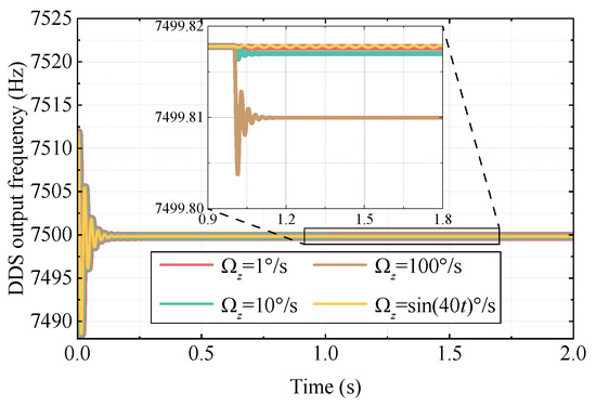
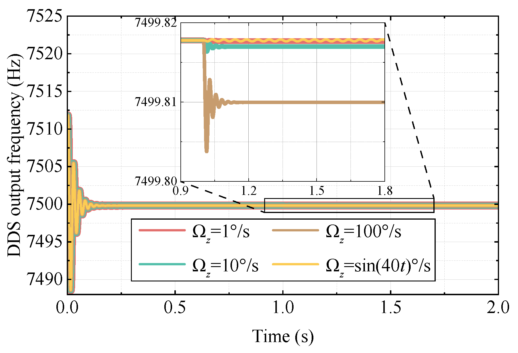
The term introduces a constant bias into the frequency-tracking loop and thus produces a tracking error. Based on the structural-parameter errors given above, Figure 7 shows the drive-mode frequency-tracking responses under different input angular rates, where a step change is applied at . For a constant input rate, the tracking loop exhibits a fixed steady-state error whose magnitude increases with the input angular rate. In addition, the variation frequency of the input angular rate causes fluctuations in the DDS output frequency. Accordingly, the cutoff frequency of the synchronous integral demodulator in the drive-mode frequency-tracking loop should be made as low as practical so as to suppress the influence of angular-rate variation on the tracking result.
Figure 7.
Effect of structural errors on drive modal-frequency tracking.
It can also be seen from Equations (58) and (59) that and are inversely proportional to the Coriolis mass . Therefore, for a fixed percentage of fabrication error in the ring resonator, increasing the effective mass involved in the Coriolis response of the two operating modes by introducing suspended lumped masses helps reduce the adverse impact of force-mismatch errors on the drive-mode amplitude control and frequency tracking.
4.3.2. Influence of Structural Errors on the Sense Mode
By moving the Coriolis term, damping-coupling term, quadrature-coupling term, and force-mismatch term in Equation (55) to the right-hand side, the sense-mode equation becomes
where
To clarify the signal composition of the forced response of the sense mode, let . According to Table 4,
Substituting Equation (65) into Equation (62) and taking the sense-electrode angular misalignment into account yields the steady-state output of the sense electrode as
where
Equation (66) shows that the sense-mode output consists of two parts: an in-phase Coriolis-like component and a quadrature-coupling component. Since synchronous integral demodulation can separate the and components, the quadrature-coupling signal does not directly interfere with Coriolis-signal detection when demodulation phase error is neglected. However, the quadrature output is usually large in amplitude, and mode matching further amplifies this component, which may saturate the control electronics. This indicates that the quadrature signal in the sense mode fundamentally originates from the frequency-coupling error , and should therefore be suppressed structurally through stiffness correction.
The modal stiffness coefficient matrix contributed by the stiffness-correction electrodes of the ring resonator is given by [27]
where , , and are determined by the geometry of the resonator stiffness-correction electrodes and the voltages applied to them.
Combining Equations (16) and (68) yields the resonator frequency matrix with electrostatic stiffness tuning taken into account
The eigenvalues of the matrix in Equation (69) and the corresponding eigenvectors are given by
where
As indicated by Equations (70) and (71), the eigenvalues of the modal-frequency matrix and the corresponding eigenvectors are jointly governed by the mass-distribution error, the stiffness error, and the electrostatic stiffness-tuning parameters. Physically, the eigenvalues of represent the resonant frequencies of the two operating modes of the ring resonator, which satisfy the following relation
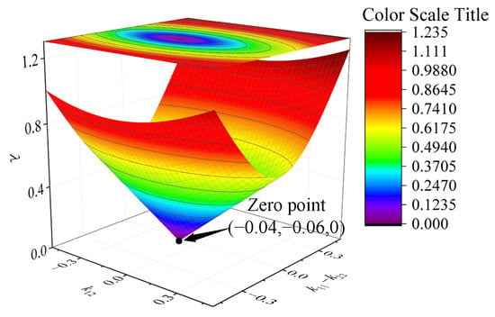
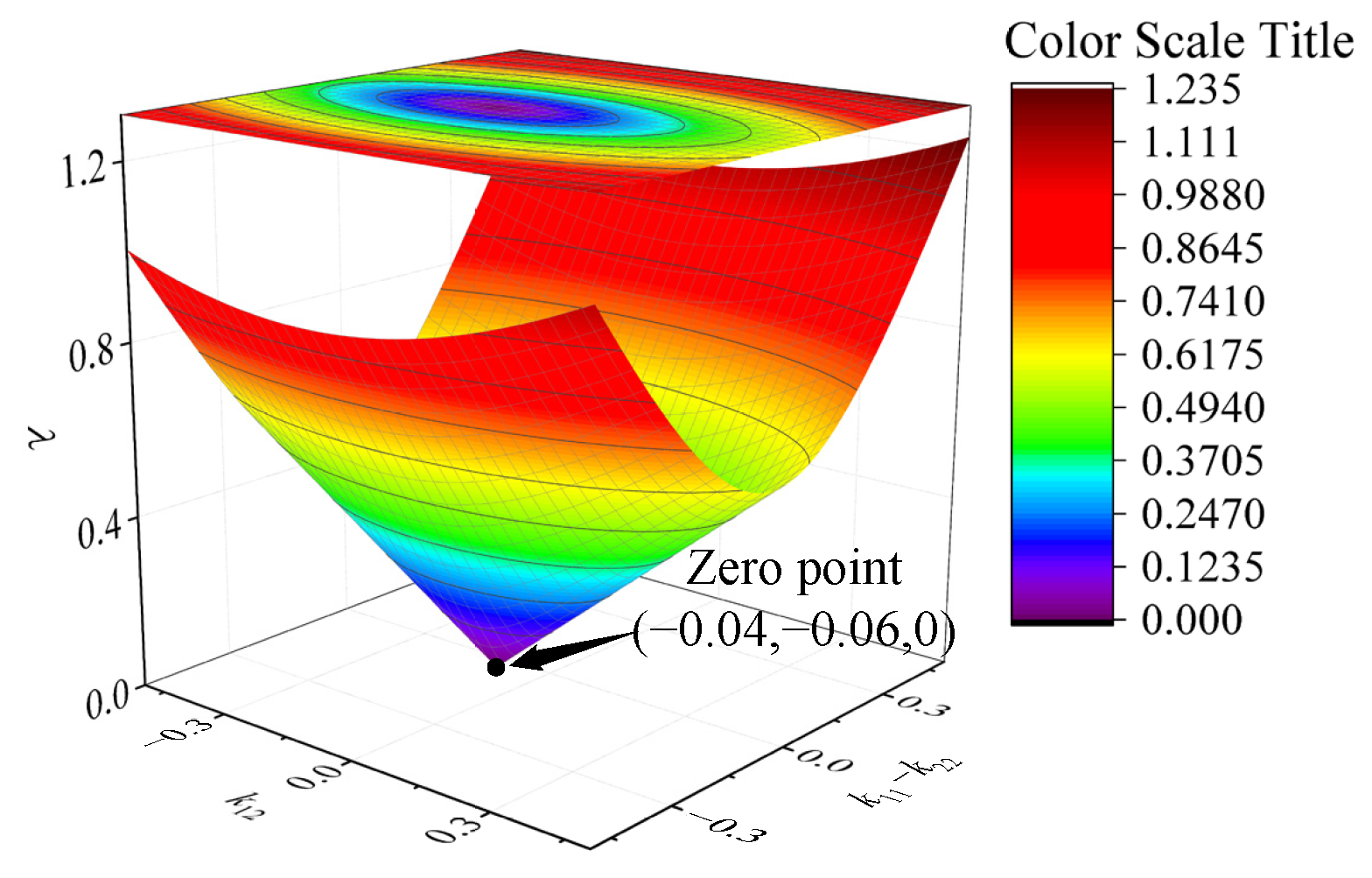
According to the above relation, the condition for achieving mode matching in the ring gyroscope is . By setting , , , and , Figure 8 illustrates the effect of variations in and on . The results indicate that, with and taken as the independent variables, the equation admits a unique solution, which satisfies the following condition
Figure 8.
Variation of with and .
Equation (74) indicates that mode matching in the ring gyroscope requires not only equal diagonal elements of , but also vanishing off-diagonal elements. Physically, this means that the prerequisite for mode matching is the removal of the quadrature-coupling stiffness. Furthermore, based on the eigenvectors in Equations (70) and (71), the orientation angle of the updated frequency principal axes can be expressed as
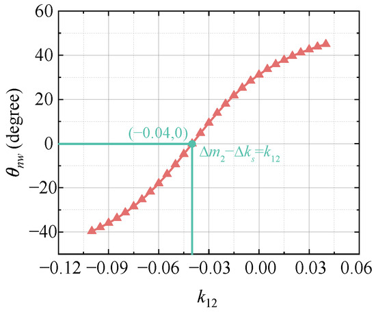
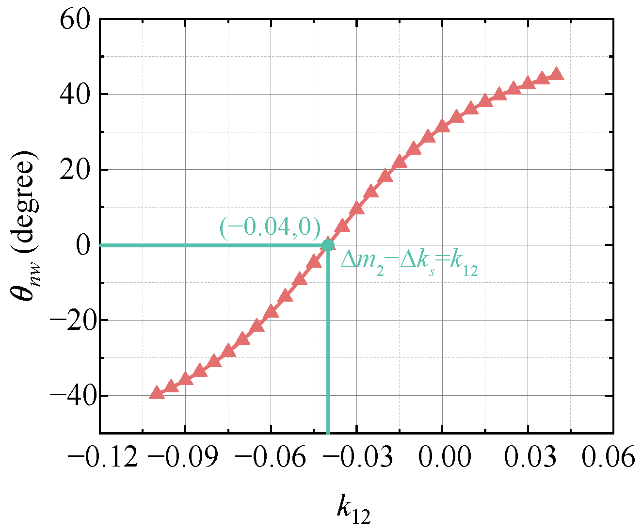
According to Equation (75), and in combination with the simulation parameters of the above stiffness and mass errors, the variation curve of the orientation angle of the frequency principal axes with respect to is plotted in Figure 9. The results show that if and only if , namely, when the condition is satisfied. The physical meaning of is that, through quadrature-stiffness correction, the frequency principal axes of the ring resonator are aligned with the modal axes, thereby laying the foundation for further achieving mode matching. Therefore, mode matching based on the electrostatic negative-stiffness effect should be implemented in two steps: quadrature-stiffness correction first, followed by modal-frequency tuning.
Figure 9.
Variation of the modal-frequency-axis orientation angle with .
Furthermore, the in-phase output in Equation (66) can be written as
where the three terms correspond to the rate signal, the damping-decay-time coupling signal, and the force-mismatch coupling signal, respectively. Because these components are in phase, they cannot be separated by synchronous integral demodulation, thereby introducing errors into rate detection.
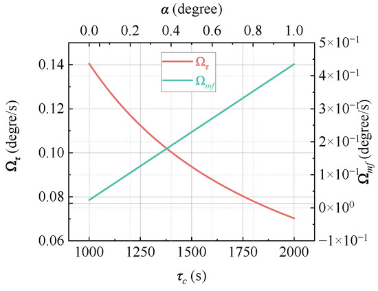
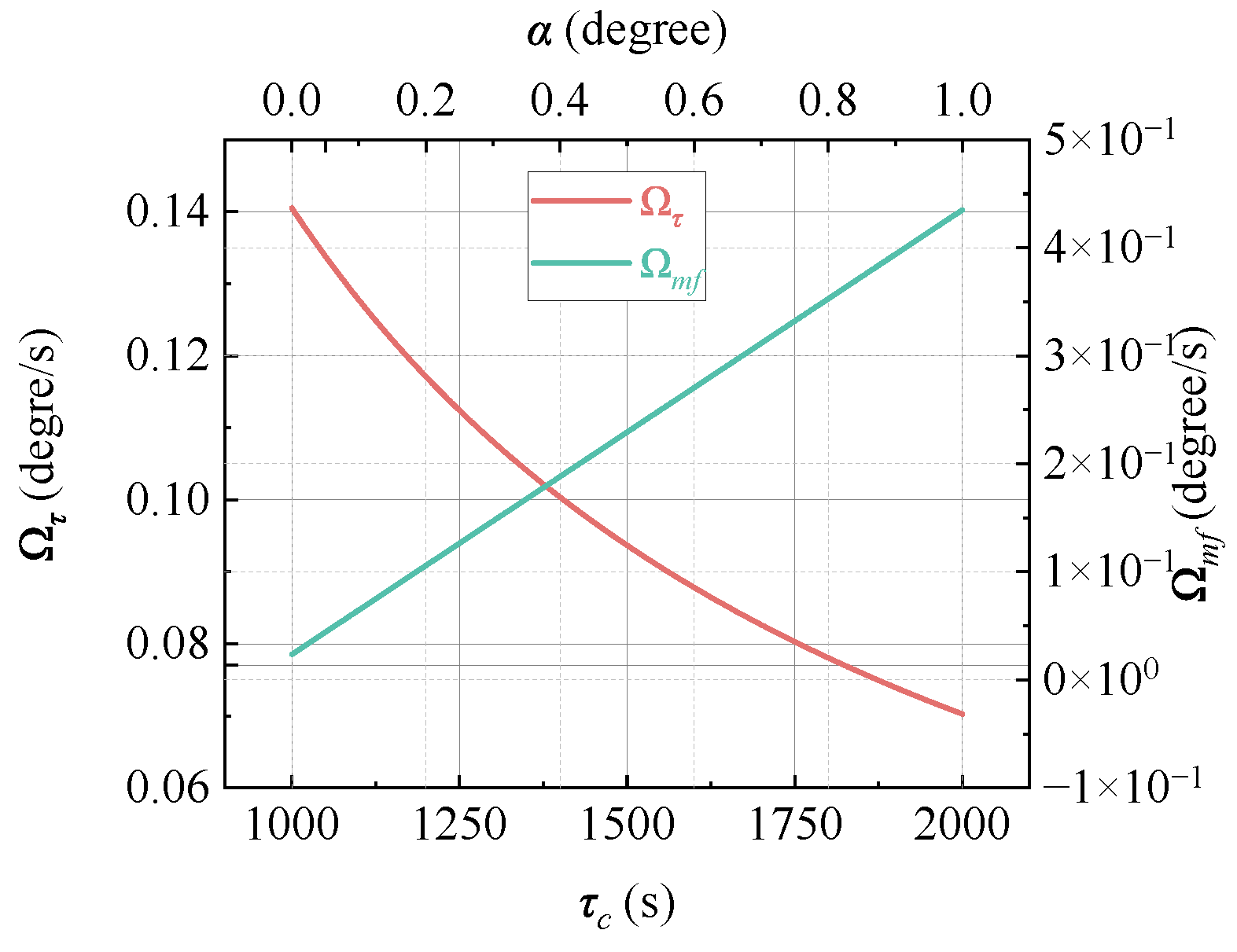
For the damping-decay-time coupling signal, its magnitude is negatively correlated with the damping-decay-time coupling term, represented here by the equivalent damping angular rate , as shown by the red curve in Figure 10. Since the damping decay time of the resonator is temperature sensitive, it is prone to variation with the ambient temperature, thereby causing output drift in the ring gyroscope. For ring gyroscopes with an axisymmetric structure, the damping-coupling error can be suppressed by means of modal reciprocity. However, this approach suffers from either limited operating bandwidth in the single-resonator implementation or high cost in the dual-resonator implementation. At present, an effective way to reduce the damping-decay-time coupling error is to increase the quality factor of the resonator, thereby increasing the value of .
Figure 10.
Equivalent input angular rate caused by damping-decay-time coupling and electrode angular errors.
For the force-coupling error signal, its magnitude is positively correlated with both the drive-mode actuation-force amplitude and the force-mismatch coefficient . For a fabricated ring resonator without post-processing, such as laser trimming, can be regarded as approximately constant. Therefore, its value can be obtained through system calibration for error compensation, or alternatively reduced by introducing suspended lumped mass blocks. In addition, is inversely related to the damping decay time of the ring resonator. Increasing the quality factor therefore also mitigates the adverse effect of the force-coupling signal. The blue curve in Figure 10 illustrates the influence of the drive-electrode angular error in on rate detection. When the mass-mismatch error is and , the equivalent rate induced by force mismatch is approximately . In general, the detection threshold of MEMS ring gyroscopes is much smaller than . Therefore, in high-precision angular-rate sensing, the force-mismatch error remains non-negligible and should be suppressed through both structural optimization and system calibration.
Under force-to-rebalance control, the electrostatic force is adjusted by the controller to maintain , and the rate information is represented by . Therefore, the coefficient in the force-mismatch term changes the gain of the force-to-rebalance control loop, thereby leading to a variation in the rate detection gain. In addition, an angular-misalignment error between the sensing-electrode axis of the Y mode and the principal axis of the Y mode also causes a gain variation in the sensed signal of the sense mode. For a fabricated ring resonator, these two error coefficients can generally be treated as constants, and their effect is essentially to alter the gain of the sense-mode detection signal. The error introduced by can be suppressed either through calibration or by increasing the lumped mass blocks, whereas the value of can be identified through calibration and compensated in subsequent measurements.
4.4. Sensitivity and Validation of Structural-Error Parameters
The proposed structural-error model provides a basis for analyzing the sensitivity of FTR system performance to parameter variations and for establishing practical parameter-identification procedures. The main structural parameters considered in this paper include modal-frequency perturbation, damping-decay-time mismatch, mass-distribution mismatch, and electrode angular misalignment. These parameters affect the gyroscope output through different physical paths. Modal-frequency perturbation mainly changes the orientation of the frequency principal axes and introduces off-diagonal frequency-coupling terms, thereby directly affecting quadrature generation and mode matching. Damping-decay-time mismatch mainly produces in-phase coupling components, which may appear as bias-like errors in the sense-mode output. Mass-distribution mismatch and electrode angular misalignment jointly affect the electrode-force-to-acceleration mapping, resulting in force mismatch, equivalent rate bias, and scale-factor variation.
Among the structural-error sources considered in this paper, the modal-frequency coupling error has the most direct influence on quadrature generation and mode frequency split. This error rotates the frequency principal axes away from the modal drive/sense axes and introduces an off-diagonal term in the modal-frequency matrix, thereby producing quadrature coupling between the two operating modes. Therefore, it is the primary structural error that should be corrected before modal-frequency tuning. In contrast, damping-decay-time mismatch and force mismatch mainly introduce in-phase coupling components and gain variations in the FTR output. Although these in-phase components do not directly determine the quadrature-stiffness correction condition, they are particularly harmful to rate-output accuracy because they cannot be separated from the useful angular-rate signal by synchronous demodulation. Therefore, modal-frequency coupling should be minimized first through quadrature-stiffness correction, while the remaining damping-related and force-mismatch-induced errors should be further compensated by calibration.
The structural-error parameters in the proposed model can be quantified through modal testing and closed-loop calibration. First, modal-frequency perturbation can be obtained from frequency-response or ring-down measurements. By exciting the resonator along different electrode axes and fitting the resonance peaks, the two modal frequencies and the orientation of the frequency principal axes can be identified. The modal-frequency coupling term can then be reconstructed from the measured modal-frequency matrix. Its validity can be checked by comparing the predicted quadrature output and mode-matching condition with the measured quadrature signal before and after electrostatic stiffness correction.
Second, damping-decay-time mismatch can be quantified from free-decay tests. After the drive or sense mode is excited and the excitation is removed, the decay envelope of the demodulated vibration signal can be fitted to extract the damping decay times along different modal axes. The damping principal-axis orientation can be further identified by repeating the decay measurement under different excitation directions. The obtained damping-decay-time matrix can be validated by comparing the predicted in-phase coupling component with the measured zero-rate output or in-phase demodulation signal.
Third, mass-distribution mismatch can be estimated indirectly through calibrated electrostatic-force excitation and modal-response measurement. Since the effective modal mass is difficult to measure directly, the mass-mismatch coefficients can be identified from the relationship between the known electrostatic actuation force and the measured modal acceleration or displacement response. In addition, finite-element simulation and fabrication-tolerance analysis can be used as auxiliary methods to estimate the expected range of mass-distribution mismatch. The identified mass-mismatch coefficients can be validated by comparing the predicted force-mismatch-induced equivalent rate bias with the measured bias variation under controlled actuation and sensing configurations. Electrode angular misalignment can be evaluated from layout geometry, optical or metrological inspection, and system-level calibration, and its effect can be validated by measuring the cross-axis actuation/sensing coupling and rate-gain variation.
The above analysis indicates that the structural errors considered in this paper are not merely theoretical perturbation terms. Instead, they can be linked to measurable modal parameters and validated through experimentally observable quantities, such as quadrature output, in-phase coupling component, equivalent rate bias, and scale-factor variation. The dominant influence paths of these structural-parameter variations are summarized in Table 5.
Table 5.
Sensitivity and validation paths of structural-error parameters.
Although the present work mainly focuses on theoretical modeling, the derived error mechanisms are consistent with previously published experimental and simulation results on MEMS ring and vibratory gyroscopes. In particular, the proposed model indicates that structural imperfections introduce modal-frequency coupling, damping-related coupling, and force mismatch, which further lead to quadrature output, in-phase coupling, rate bias, and scale-factor variation. Similar physical phenomena have been reported in previous studies.
Hosseini-Pishrobat and Tatar developed a mathematical model for a MEMS vibrating ring gyroscope with structural defects and material anisotropy, and showed that structural imperfections can be used to explain frequency split and quadrature error in fabricated devices [19]. This is consistent with the present conclusion that the quadrature output originates from modal-frequency coupling and should be suppressed through stiffness correction. In addition, Hosseini-Pishrobat et al. experimentally investigated stress effects in a MEMS ring gyroscope and reported that the predicted frequencies, quadrature errors, and in-phase errors agreed with experimental measurements [30]. This provides external experimental support for the use of modal-frequency and damping-related parameters to characterize structural-error-induced output components. The conclusions related to FTR operation are also consistent with reported control-level studies. Hu et al. investigated the influence of mode mistuning on FTR closed-loop control and demonstrated that mode matching improves the measurement performance of MEMS Coriolis vibratory gyroscopes [31]. This supports the present conclusion that electrostatic mode matching should be performed by first suppressing quadrature-stiffness coupling and then tuning the modal frequencies. Furthermore, Bu et al. showed that quadrature coupling error is an important factor affecting the detection output and zero-rate output of MEMS gyroscopes under FTR closed-loop detection [13]. This agrees with the present analysis that quadrature and in-phase coupling components must be separately considered in closed-loop rate measurement.
Therefore, although direct experimental verification of the fabricated device is not included in this paper, the main conclusions of the proposed model are consistent with previously reported experimental and simulation observations. The comparison between the present model conclusions and the published observations is summarized in Table 6. These comparisons support the physical validity and practical applicability of the proposed error-analysis framework. Future work will further verify the model quantitatively using fabricated MEMS ring gyroscopes and closed-loop calibration experiments.
Table 6.
Comparison between the present model conclusions and published experimental or simulation results.
5. Conclusions
The unified dynamic-modeling and error-analysis framework for the FTR-operated MEMS ring gyroscope has been established in this paper. Based on the equivalent mass-point model, the influences of principle-related inertial-acceleration errors and structural errors on rate measurement were systematically investigated.
The analysis shows that the inertial-acceleration errors associated with the sensing principle have negligible effects on both the drive mode and the sense mode under practical rate-sensing conditions. Therefore, for the FTR-operated ring gyroscope considered here, rate-measurement errors are dominated by structural non-idealities rather than by principle-related inertial terms. After introducing mass-distribution mismatch and electrode angular misalignment, the damping-decay-time matrix and modal-frequency matrix were reformulated in terms of measurable modal parameters. The results show that structural errors mainly manifest themselves through damping-decay-time coupling, modal-frequency coupling, and force mismatch. These errors degrade drive-mode amplitude control and frequency tracking, alter the gain of sense-mode detection, and introduce in-phase coupling signals into the FTR output. In contrast, the quadrature output fundamentally originates from modal-frequency coupling and should be suppressed through stiffness correction. Furthermore, by introducing the electrostatic stiffness matrix, the conditions for modal-frequency matching were derived. The analysis indicates that true mode matching requires not only equal diagonal elements of the modal-frequency matrix but also vanishing off-diagonal elements.
Although the present study is mainly theoretical, the derived error mechanisms are consistent with previously reported experimental and simulation observations on MEMS ring and vibratory gyroscopes. Future work will focus on the experimental validation of the proposed error model using fabricated MEMS ring gyroscopes, as well as the quantitative identification of structural-error parameters. In addition, closed-loop compensation strategies, including quadrature-stiffness correction, modal-frequency tuning, and temperature-dependent damping-coupling compensation, will be further investigated to improve the bias stability and rate-measurement accuracy of FTR-operated MEMS ring gyroscopes.
Author Contributions
Conceptualization, C.D., F.Y. and J.J.; methodology, C.D.; formal analysis, C.D.; investigation, C.D.; writing—original draft preparation, C.D.; writing—review and editing, F.Y. and J.J.; supervision, F.Y. and J.J. All authors have read and agreed to the published version of the manuscript.
Funding
This research received no external funding.
Institutional Review Board Statement
Not applicable.
Informed Consent Statement
Not applicable.
Data Availability Statement
The original contributions presented in this study are included in the article. Further inquiries can be directed to the corresponding author.
Conflicts of Interest
The authors declare no conflicts of interest.
References
- Gill, W.A.; Howard, I.; Mazhar, I.; McKee, K. A review of MEMS vibrating gyroscopes and their reliability issues in harsh environments. Sensors 2022, 22, 7405. [Google Scholar] [CrossRef] [Scilit]
- Chen, Z.; Yan, K.; Wang, X.; Li, R.; Zhang, A.; Wang, X.; Wang, Y.; Gao, P.; Li, H.; Wang, C.; et al. MEMS gyroscopes in different operation modes: A review. Measurement 2025, 249, 116996. [Google Scholar] [CrossRef] [Scilit]
- Wei, W.; Tian, H.; Chen, K.; Wang, F.; Lu, Z.; Chen, F.; Cao, H.; Xie, H. Triaxial MEMS Gyroscopes: A Review. IEEE Sens. J. 2025, 25, 35687–35707. [Google Scholar] [CrossRef] [Scilit]
- Ahi, B. MEMS gyroscope technology in defence systems: An application-oriented perspective with new analytical results. Def. Technol. 2026, 55, 389–406. [Google Scholar] [CrossRef] [Scilit]
- Chen, D.; Guo, Y.; Huo, P.; Li, Q. MEMS Gyroscope technology for Low-Earth orbit aerospace: Technologies, environmental challenges, and emerging design strategies. Acta Astronaut. 2026, 243, 280–290. [Google Scholar] [CrossRef] [Scilit]
- Kuang, Y.; Huo, X.; Guo, W.; Li, X.; He, J.; Mao, Q.; Ma, X.; Liu, J. Research on the method of optimizing the stress and improving the performance for MEMS gyroscope based on the cantilever-plate structure. Micromachines 2025, 16, 372. [Google Scholar] [CrossRef] [Scilit]
- Ouyang, C.; He, W.; Jia, L.; Wang, P.; Zhao, K.; Xing, F.; You, Z. Full-System Simulation and Analysis of a Four-Mass Vibratory MEMS Gyroscope. Micromachines 2025, 16, 414. [Google Scholar] [CrossRef] [Scilit]
- Yu, S.; Sun, J.; Zhang, Y.; Xi, X.; Lu, K.; Shi, Y.; Xiao, D.; Wu, X. Real-time correction of gain nonlinearity in electrostatic actuation for whole-angle micro-shell resonator gyroscope. Microsyst. Nanoeng. 2024, 10, 164. [Google Scholar] [CrossRef] [Scilit]
- Li, R.; Wang, X.; Yan, K.; Chen, Z.; Ma, Z.; Wang, X.; Zhang, A.; Lu, Q. Interactive errors analysis and scale factor nonlinearity reduction methods for Lissajous frequency modulated MEMS gyroscope. Sensors 2023, 23, 9701. [Google Scholar] [CrossRef] [Scilit]
- Gill, W.A.; Howard, I.; Mazhar, I.; McKee, K. Design and considerations: Microelectromechanical system (MEMS) vibrating ring resonator gyroscopes. Designs 2023, 7, 106. [Google Scholar] [CrossRef] [Scilit]
- Chen, C.; Zhou, J.; Wang, H.; Fan, Y.; Song, X.; Xie, J.; Bäck, T.; Wang, H. Machine learning-driven discovery of high-performance MEMS disk resonator gyroscope structural topologies. Microsyst. Nanoeng. 2024, 10, 161. [Google Scholar] [CrossRef] [Scilit]
- Hosseini-Pishrobat, M.; Tatar, E. Modeling temperature effects in a MEMS ring gyroscope: Toward physics-aware drift compensation. J. Microelectromech. Syst. 2025, 34, 150–163. [Google Scholar] [CrossRef] [Scilit]
- Bu, F.; Guo, S.; Fan, B.; Wang, Y. Effect of quadrature control mode on ZRO drift of MEMS gyroscope and online compensation method. Micromachines 2022, 13, 419. [Google Scholar] [CrossRef] [Scilit]
- Jia, J.; Song, Z.; Gao, S.; Gao, Y.; Cao, H. Bandwidth expansion for force-to-rebalance measurement of MEMS gyroscopes based on equivalent unit negative feedback loop. IEEE/ASME Trans. Mechatron. 2025, 30, 4613–4624. [Google Scholar] [CrossRef] [Scilit]
- Askari, S.; Asadian, M.H.; Shkel, A.M. High quality factor MEMS gyroscope with whole angle mode of operation. In Proceedings of the 2018 IEEE International Symposium on Inertial Sensors and Systems (INERTIAL), Lake Como, Italy, 26–29 March 2018; pp. 1–4. [Google Scholar]
- Kline, M. Frequency Modulated Gyroscopes. Ph.D. Thesis, University of California, Berkeley, CA, USA, 2013. [Google Scholar]
- Zhang, W.; Yu, X.; Wang, Y.; Zhang, H.; Sha, X.; Liu, X.; Yin, L.; Fu, Q.; Li, X. An interface ASIC for MEMS disk resonator gyroscope with 0.018°/h bias instability and 108 Ppm scale factor nonlinearity. IEEE Trans. Circuits Syst. I Regul. Pap. 2025, 73, 113–125. [Google Scholar] [CrossRef] [Scilit]
- Bai, Z.; Cui, J.; Zhao, Q.; Yang, Z.; Yan, G. Initial frequency split reduction of MEMS ring gyroscope based on cascaded springs geometrical compensation. Electron. Lett. 2019, 55, 806–808. [Google Scholar] [CrossRef] [Scilit]
- Hosseini-Pishrobat, M.; Tatar, E. Modeling and analysis of a MEMS vibrating ring gyroscope subject to imperfections. J. Microelectromech. Syst. 2022, 31, 546–560. [Google Scholar] [CrossRef] [Scilit]
- Hosseini-Pishrobat, M.; Tatar, E. Analysis of quadrature and frequency split in a MEMS vibrating ring gyroscope with structural imperfections. In Proceedings of the 2021 21st International Conference on Solid-State Sensors, Actuators and Microsystems (Transducers), Orlando, FL, USA, 20–24 June 2021; pp. 1291–1294. [Google Scholar]
- Wang, X.; Wu, K.; Wang, C.; Li, Q.; Hou, Z.; Xiao, D.; Wu, X. Research on the mass adding and removing combined mechanical trimming method of the ring MEMS gyroscope. Micromachines 2023, 14, 1957. [Google Scholar] [CrossRef] [Scilit]
- Chouvion, B.; McWilliam, S.; Popov, A.A. Effect of nonlinear electrostatic forces on the dynamic behaviour of a capacitive ring-based Coriolis Vibrating Gyroscope under severe shock. Mech. Syst. Signal Process. 2018, 106, 395–412. [Google Scholar] [CrossRef] [Scilit]
- Ma, Z.; Chen, X.; Jin, X.; Jin, Y.; Zheng, X.; Jin, Z. Effects of structural dimension variation on the vibration of MEMS ring-based gyroscopes. Micromachines 2021, 12, 1483. [Google Scholar] [CrossRef] [Scilit]
- Ahn, C.H.; Ng, E.J.; Hong, V.A.; Yang, Y.; Lee, B.J.; Flader, I.; Kenny, T.W. Mode-matching of wineglass mode disk resonator gyroscope in (100) single crystal silicon. J. Microelectromech. Syst. 2014, 24, 343–350. [Google Scholar] [CrossRef] [Scilit]
- Qin, Z.; Gao, Y.; Jia, J.; Ding, X.; Huang, L.; Li, H. The effect of the anisotropy of single crystal silicon on the frequency split of vibrating ring gyroscopes. Micromachines 2019, 10, 126. [Google Scholar] [CrossRef] [Scilit] [PubMed]
- Ren, J.; Zhou, T.; Zhou, Y.; Li, Y.; Su, Y. An in-run automatic mode-matching method with amplitude correction and phase compensation for MEMS disk resonator gyroscope. IEEE Trans. Instrum. Meas. 2023, 72, 7505911. [Google Scholar] [CrossRef] [Scilit]
- Jia, J.; Song, Z.; Gao, Y.; Gao, S.; Cao, H. A low-complexity in-run modal frequency tuning method for MEMS disk gyroscopes without gain calibration and phase shifting. IEEE Trans. Instrum. Meas. 2024, 73, 7504512. [Google Scholar] [CrossRef] [Scilit]
- Jia, J.; Zhang, H.; Gao, S.; Gao, Y.; Chen, F.; Cao, H. Phase error analysis for MEMS gyroscopes operational modes based on force-to-rebalance rate measurement mode. Microsyst. Nanoeng. 2026, 12, 86. [Google Scholar] [CrossRef] [Scilit]
- Gill, W.A.; Howard, I.; Mazhar, I.; McKee, K. A Detailed Analysis of the Dynamic Behavior of a MEMS Vibrating Internal Ring Gyroscope. Micromachines 2024, 15, 1107. [Google Scholar] [CrossRef] [Scilit]
- Hosseini-Pishrobat, M.; Erkan, D.; Tatar, E. Analytical and Experimental Study of Stress Effects in a MEMS Ring Gyroscope. Sens. Actuators A Phys. 2023, 362, 114639. [Google Scholar] [CrossRef] [Scilit]
- Hu, Z.; Gallacher, B. A Mode-Matched Force-Rebalance Control for a MEMS Vibratory Gyroscope. Sens. Actuators A Phys. 2018, 273, 1–11. [Google Scholar] [CrossRef] [Scilit]

Disclaimer/Publisher’s Note: The statements, opinions and data contained in all publications are solely those of the individual author(s) and contributor(s) and not of MDPI and/or the editor(s). MDPI and/or the editor(s) disclaim responsibility for any injury to people or property resulting from any ideas, methods, instructions or products referred to in the content. |
© 2026 by the authors. Licensee MDPI, Basel, Switzerland. This article is an open access article distributed under the terms and conditions of the Creative Commons Attribution (CC BY) license.