Abstract
Amid rapid global aviation development and increasingly stringent safety standards, aerostats demonstrate vast potential in environmental monitoring, communication relay, cargo transportation, and other applications. However, their operational safety has become a critical focus. These systems face complex flight environments and dynamic mission requirements that demand exceptionally high safety control standards. As the core component, the safety control computer directly determines the overall safety and stability of aerostat operations. This study employed a systems engineering methodology integrating hardware selection, software architecture design, fault diagnosis, and fault tolerance to develop a universal safety control computer system with high reliability, robust real-time performance, and adaptive capabilities. By adopting high-performance processors, redundant design techniques, and modular software programming, the system significantly enhanced anti-interference performance and fault recovery capabilities. These improvements ensured precise and rapid safety control monitoring under diverse operational conditions. Experimental validation demonstrated the system’s effectiveness in supporting both remote and autonomous safety control modes, substantially mitigating flight risks. This technological breakthrough provides robust technical support for the large-scale development and safe operation of universal aerostat systems, while offering valuable insights for safety control system design in other aerospace vehicles.
1. Introduction
Aerostats constitute a distinctive class of lighter-than-air vehicles that offer critical capabilities in modern aerospace systems [1]. Their advantages of low energy consumption, long endurance, and high payload capacity make them highly effective in environmental monitoring, communication relay, cargo transportation, and other applications. Recent technological developments have enabled the transition of aerostat platforms from primarily military surveillance roles to diverse civilian applications including logistics networks and atmospheric research initiatives [2]. However, the complex operational environments and stringent safety requirements of aerostats pose significant challenges to their computing systems [3].
Aerostats typically comprise four distinct categories: high-altitude balloons, near-space airships, low-altitude airships, and tethered balloons. Despite differences in operational altitudes and structural configurations, these systems share nearly identical fundamental safety control requirements.
To enhance flight safety in aerostats, our research team has implemented a functional decoupling strategy within the avionics computing hierarchy. This innovative approach isolates emergency descent control functions from computing systems, resulting in a dedicated safety control computer with an autonomous hardware/software co-design.
The primary function of the aerostat safety control computer is to ensure controlled flight operations and continuous status tracking throughout all operational phases.
Aerostats rely on buoyancy for flight. In emergencies—such as a loss of control or boundary breaches—the system must activate the emergency helium venting system to rapidly release buoyant gas from the aerostat envelope, enabling a swift and controlled descent.
While this core requirement remains consistent across platforms, existing safety control implementations exhibit critical limitations rooted in platform-specific customization:
- Installation inefficiency: current systems are tailored to individual aerostat parameters—envelope dimensions (ranging from 10 m3 for small, tethered balloons to 500,000 m3 for stratospheric platforms), external communication interfaces (e.g., RF, optical, or satellite links), and flight profiles. This results in incompatible form factors, with control unit volumes varying by over 300% (0.2–0.8 L), complicating standardized mounting and integration.
- Operational complexity: divergent safety protocols across platforms force operators to master multiple control strategies. Field studies indicate a 23% increase in human error rates when managing heterogeneous systems compared to unified interfaces.
- Maintenance and upgradability barriers: this architectural fragmentation impedes software updates and hardware iterations, extending development cycles by 40–60% for cross-platform compatibility adaptations.
These limitations underscore an urgent need for universal safety control architectures that reconcile platform-specific operational demands with standardized design frameworks—a challenge yet to be systematically addressed in aerostat research.
With the rapid development of electronic information technologies and artificial intelligence, aerospace computing systems have achieved significant progress in recent years, primarily manifested in three key areas:
Enhancement of chip radiation tolerance: the mass production of radiation-hardened components, particularly field-programmable gate arrays (FPGAs) with single-event upset mitigation capabilities, has enabled high-reliability avionics designs for near-space aerostats [4]. However, these radiation-tolerant solutions often entail prohibitively high costs, rendering them impractical for low-altitude aerostats operating under tight budget constraints.
High-reliability redundant architecture design: fault-tolerant architectures, which integrate redundant resources and error masking mechanisms at critical system nodes, have become a focal point in aerospace flight control systems. A 2024 NASA report highlights the emergence of highly integrated modular computing systems for small spacecraft, with heterogeneous FPGA+ARM architectures dominating the market [5]. Studies such as the FPGA-based fault-tolerant framework proposed in [6] provide standardized and scalable redundancy management solutions for avionics, while the triplex redundant flight control system utilizing the M1394B bus [7] demonstrates advancements in real-time performance and reliability. Nevertheless, these architectures are predominantly tailored for conventional aviation flight control systems, resulting in excessive complexity and resource overhead when applied to aerostat safety control scenarios.
Advancements in intelligent safety algorithms: AI-driven strategies, including reinforcement learning for dynamic path planning in turbulent wind fields [8] and digital twin technology for mission reliability enhancement [9], have shown promise in simulation environments. However, their implementation in aerostat safety control systems faces two fundamental constraints: (1) the inherent simplicity and determinism required for aerostat emergency protocols, and (2) stringent limitations on computational resources within safety control computers, which typically prioritize lightweight operations over complex AI computations.
However, these advancements demonstrate critical limitations in meeting the essential design requirements of cost-effectiveness, simplified implementation, and cross-platform compatibility for universal safety control computer architectures.
To address these requirements, this study aims to design and implement a universal safety control computer for aerostats to enhance operational safety, reliability, and intelligence [10,11,12]. The proposed system integrates high-performance processors and advanced algorithms to improve computational efficiency and real-time performance, thereby meeting the demands of complex tasks. By incorporating redundant design and fault-tolerant mechanisms, it strengthens system stability to ensure safe operations in extreme conditions. Furthermore, its modular architecture and compatibility with diverse interfaces support flexible adaptation to technological innovations, which enables broader applications for aerostats [13].
The practical value of this research lies in three key aspects:
Enhanced Safety: The universal safety control computer significantly reduces accident risks while safeguarding personnel and equipment.
Mission Efficiency: Its high performance and intelligent features expand aerostats’ utility in environmental monitoring, logistics, and emergency response.
Industry Advancement: Standardized modular design lowers research, development, and maintenance costs, thereby accelerating the industrialization of aerostat technology.
In summary, as aerostats become increasingly vital in modern aviation, the safety control computer—their operational core—directly determines their viability [14]. This study addresses existing deficiencies by developing a universal safety control computer, thereby advancing both the safety and intelligence of aerostat operations. The findings offer theoretical insights and practical solutions, with implications extending to safety systems in other aerospace platforms [15,16,17].
The remainder of this paper is organized as follows. Section 2 details the design principles of the universal safety control computer, focusing on functional requirements and architectural innovation. Section 3 presents the hardware system design, including redundancy architectures and modular integration strategies. Section 4 elaborates on the software system design, emphasizing the triple-module voting mechanism and fault-tolerant synchronization protocols. Section 5 introduces safety control strategies, including the remote safety control strategy and autonomous safety control strategy, with a focus on the implementation process of geofencing—the most widely used method in autonomous safety control. Section 6 concludes this study with performance evaluations and future research directions.
2. Design Principles of the Universal Safety Control Computer for Aerostats
The universal safety control computer performs multiple critical tasks, including safety control, status monitoring, and fault diagnosis [18]. For safety control, it processes data from various sensors in real time and generates control commands based on predefined algorithms to ensure stable flight and precise landing [19]. Regarding status monitoring and fault diagnosis, it continuously tracks the operational status of all subsystems, while promptly identifying and addressing potential failures to maintain safe operations [20].
And it typically requires independent control links and multiple helium venting mechanisms to address diverse failure scenarios.
As shown in Figure 1 (aerostat safety control system diagram), the universal safety control computer operates in three stages:
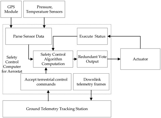
Figure 1.
Aerostat safety control system diagram.
Data Acquisition: collects real-time sensor data, including the aerostat’s latitude, longitude, altitude, temperature, atmospheric pressure, and power supply voltage.
Data Processing: analyzes sensor data to determine operational status (e.g., normal flight, boundary breach, or system failure).
Controlled Response: triggers the orderly activation of emergency helium venting devices (e.g., pyrotechnic actuators) upon the detection of anomalies (e.g., boundary violations) or descent commands. This ensures rapid gas expulsion and a safe, controlled descent trajectory.
The design is characterized by the following features.
- 1.
- Universal Design Features:
Multi-interface compatibility: preconfigured data interfaces accommodate diverse external devices: 4 × CAN bus interfaces; 10 × RS422 interfaces; 2 × RS485 interfaces; 4 × RS232 interfaces.
- 2.
- Scalable Emergency Venting:
Twelve preconfigured helium venting device driver interfaces support aerostats of varying sizes.
- 3.
- Triple Modular Redundancy (TMR):
The main control unit employs a triple modular redundancy design to enhance system reliability and stability. This architecture ensures continuous operation even if one or two modules fail, which is critical for aviation systems requiring mission-critical reliability.
3. Hardware System Design
3.1. Architecture Design for Resource Demand Resolution
FPGAs (field-programmable gate arrays) offer significant advantages due to their abundant resources and high configurability [21]. The ARM-FPGA hybrid architecture leverages the FPGA’s dynamic reconfigurability to extend system resources, as illustrated in Figure 2.
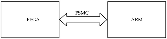
Figure 2.
ARM-FPGA architecture for resource expansion.
In this design, the ARM processor controls FPGA read/write operations through the FSMC (Flexible Static Memory Controller) bus. The FPGA functionally replaces traditional “ARM + peripheral chip” architectures by consolidating multiple expansion chip functionalities into a single programmable device. This integration achieves three key advantages: enhanced system compactness through component reduction, lower power consumption from simplified interconnects, and improved reliability through minimized signal integrity issues. Furthermore, the FPGA’s hardware reconfigurability enables the rapid adaptation to evolving requirements through HDL (Hardware Description Language) modifications, eliminating physical hardware redesign cycles.
The ARM processor accesses FPGA resources through dedicated address space allocation, enabling the seamless integration of FPGA-based peripherals (e.g., I/O modules and communication interfaces) onto the ARM’s extended data/address bus. These FPGA-implemented peripherals are formally designated as IP cores (Intellectual Property cores)—pre-verified, reusable logic blocks implementing specific functions. Typical implementations include I/O expansion modules, UART controllers, and custom communication interfaces.
Unified IP Core Abstraction Model: To standardize bus interfacing for heterogeneous IP cores, we implement a black-box abstraction model where the following applies:
- Configuration Registers (ARM-writable): store control parameters (e.g., UART baud rates and GPIO directions).
- Result Registers (ARM-readable): contain processed data outputs and status flags (e.g., received serial data and interrupt status).
As illustrated in Figure 3, this model establishes a consistent access paradigm where the following applies:
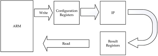
Figure 3.
ARM configuration and read/write model for IP cores.
- Each IP core occupies a unique memory-mapped address range.
- ARM interacts with cores using standard read/write operations identical to external SRAM access.
- Scalability is inherent—core addition/removal only requires address space reallocation.
Through FPGA reconfiguration via ARM-based software control, the system enables dynamic interface reconfiguration—including the on-demand deployment of industrial communication protocols (CAN bus, RS485, etc.)—to satisfy mission-specific aerostat safety control demands.
3.2. Architecture Design for Reliability Requirements
Aerostat safety control systems demand ultra-high reliability as a paramount requirement, with power consumption and weight being secondary considerations. To meet this objective, we adopt a passive redundancy architecture tailored to aerostat safety control needs, which prioritizes fault containment over error correction. Unlike active redundancy (which relies on error detection and backup switching), passive redundancy shields faulty outputs to prevent error propagation. A common passive approach is the N-Modular Redundancy (NMR) system with a voting mechanism [22], as shown in Figure 4.
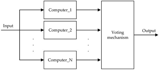
Figure 4.
N-Modular Redundancy architecture.
In this architecture, N identical computer systems process input signals simultaneously. A voter compares their outputs and selects the majority result as the system’s final output. For an odd N, the system can tolerate up to (N − 1)/2 failures. Balancing reliability, cost, complexity, and power, triple modular redundancy (TMR) is widely adopted [23]. TMR offers rapid error masking, high real-time responsiveness, and scalability to increase redundancy for enhanced reliability. This makes it ideal for mission-critical, real-time aviation systems [24].
Based on the comprehensive design considerations, this system adopts a passive triple modular redundancy (TMR) architecture where three modules cross-monitor outputs, perform majority voting, and isolate faults. The ARM software (version 1.0) implements redundancy management tasks to synchronize operations across the three ARM modules, execute consensus-based output validation through a software voter, and autonomously isolate defective components, thereby ensuring fault-tolerant system behavior.
3.3. Hardware Architecture Design
The safety control system employs a synergistic ARM-FPGA architecture that capitalizes on their complementary strengths, effectively addressing the limitations inherent in single-processor solutions. Figure 5 illustrates the comprehensive hardware architecture.
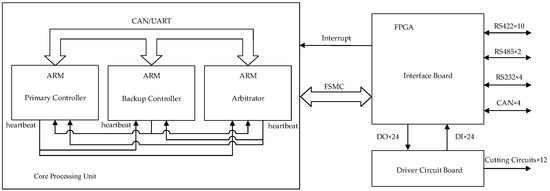
Figure 5.
Hardware architecture overview.
The system comprises three principal subsystems: the core computing component, interface board, and driver circuit board, each fulfilling distinct functional requirements.
3.3.1. Core Computing Component
The core computing component is constructed using three identical ARM-based circuit modules, featuring a unified hardware design that simplifies maintenance.
Each ARM processor executes mission-critical operations, including data parsing and protocol conversion, system configuration management, and operational parameter optimization.
The software defines the initial roles for the three identical ARM-based circuit modules.
- Primary controller: maintains operational control during nominal conditions.
- Backup controller: assumes control authority upon primary failure detection.
- Arbitrator: implements real-time health monitoring and coordinates control authority transitions.
3.3.2. Interface Board
FPGA-centric design: implements external interface functionalities through FPGA programming.
Expanded interfaces include the following:
- 16 × UART (configured via level-shifting chips,10 × RS422,4 × RS232,2 × RS485);
- 4 × CAN interfaces (compliant with standard protocols via transceivers);
- 24 × Digital Input (DI) and 24 × Digital Output (DO) channels.
3.3.3. Driver Circuit Board
The driver circuit board serves as the final-stage interface in the hardware architecture, translating validated computational outputs into actuator drive signals. The design incorporates redundant safeguards against unintended operations to ensure system integrity.
- Signal Conversion:
- Converts DO signals from the interface board into the voltage levels required for the helium venting device driver.
- Collects feedback signals from these devices, converts them into DI signals, and relays the processed signals to the safety controller via the FSMC bus.
- 2.
- Anti-Misactivation Safeguard:
- Employs two series-connected relays per cutting circuit, where the simultaneous closure of both relays is required to activate a single cutting device.
- Supports 12 cutting devices with real-time status monitoring capabilities.
3.4. Modular Design
The universal safety control computer for aerostats employs a modular architecture. The chassis integrates three critical subsystems: the core computing component, interface board, and driver circuit board.
Notably, the core computing component implements triple modular redundancy (TMR) through three identical computing nodes, providing fault-tolerant operation and scalable processing capacity.
Refer to Figure 6 for modular chassis design details.
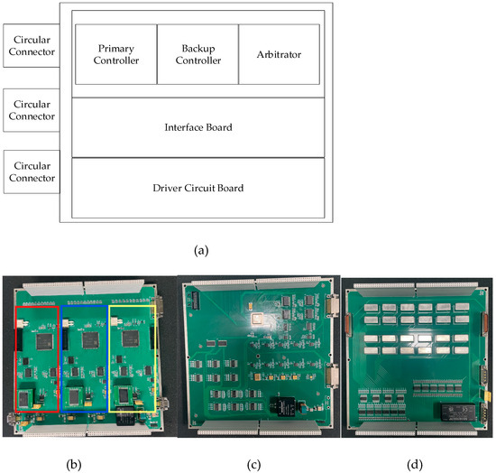
Figure 6.
(a) modular chassis design; (b) core computing component; (c) driver circuit board; (d) driver circuit board.
4. Software System Design
4.1. Software Architecture Design
The software development framework for the aerostat safety control computer follows a three-layer hierarchical architecture, where each lower layer provides essential resources and functionality to the upper layers. This structured approach encompasses hardware drivers, operating systems, and application tasks.
- Hardware Driver Layer:
- Tasks: power/clock initialization, ARM core initialization, FPGA configuration loading, and peripheral interface setup.
- Implementation: uses STM32CubeMX to generate C-language hardware initialization code via its graphical interface, significantly reducing development time and cost.
- 2.
- Operating System Layer:
- Tasks: real-time OS boot, system clock initialization, application task initialization, semaphore setup, and user task generation.
- Platform Selection: μC/OS-III, a real-time operating system.
- 3.
- Application Task Layer:
Operational Responsibilities: continuous system state monitoring, secure data transmission management, autonomous and remote safety control implementation, fault detection and recovery protocols, redundant module synchronization mechanisms, failover switching procedures.
The complete architectural overview is presented in Figure 7, illustrating the hierarchical relationships and data flow between layers.
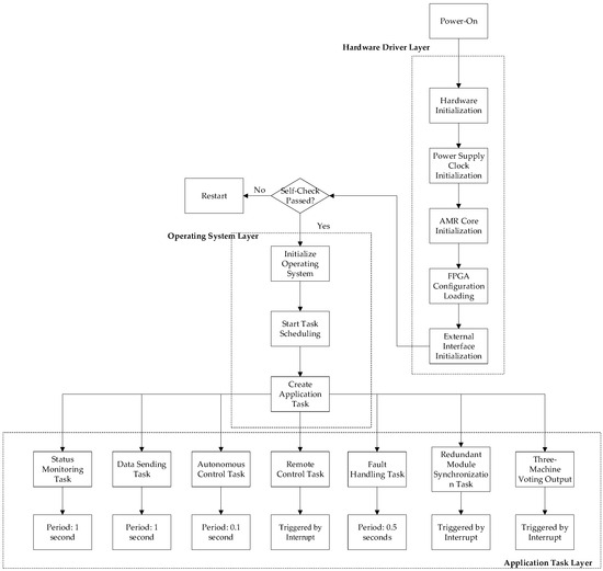
Figure 7.
Software architecture.
The difficulty of this part is the three machine voting output tasks, which will be introduced in subsequent chapters.
4.2. Triple-Module Voting Mechanism
The fault-tolerant architecture employs three coordinated components: voting, synchronization, and fault handling, working in concert to ensure high-reliability system outputs through a robust voting protocol.
4.2.1. Voting Task
The safety control computer initiates voting procedures when critical decisions are required. The program flowchart of the voting task is shown in Figure 8.
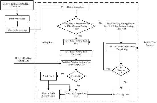
Figure 8.
Voting task.
Process (Take Module A as an example):
- 1.
- Semaphore Activation:
Upon receiving a semaphore for a pending instruction, Module A verifies whether Modules B and C have initiated the voting task.
- 2.
- Synchronization Protocol:
If either module is inactive, Module A transmits synchronization flags to both Modules B and C, then awaits their voting inputs.
- 3.
- Consensus Resolution:
Upon receiving responses:
A majority voting algorithm determines the final output.
Modules producing divergent results are flagged (incrementing their fault counters by +1).
- 4.
- Timeout Handling:
If a module fails to respond within the specified timeout period:
The non-responsive module is designated as faulty (fault counter +1). A dual-module voting sequence is initiated with the remaining operational modules.
4.2.2. Synchronization Task
After reaching a fixed task node (e.g., after five voting cycles), the synchronization task will be called. The flowchart of the synchronization task is shown in Figure 9.
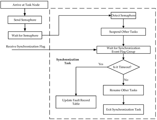
Figure 9.
Synchronization task.
Process:
- 1.
- Synchronization Trigger:
The system generates synchronization semaphores at defined task nodes.
- 2.
- State Suspension:
All tasks enter a suspended state pending synchronization flag reception.
- 3.
- Process Resumption:
Following successful confirmation from all modules, normal task execution resumes.
4.2.3. Fault Handling Task
The fault handling task comprises two coordinated subtasks: fault logging subtask and fault resolution subtask.
The flowchart of the fault handling task is shown in Figure 10.
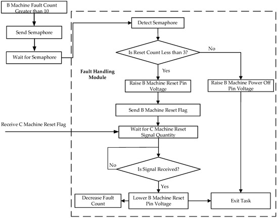
Figure 10.
Fault handling task.
- Fault logging subtask: Periodically shares fault count tables across modules via the bus, aggregating counts from all three ARMs.
- Fault resolution subtask: Executes corrective actions based on fault thresholds.
Process (take Module A as an example):
- Threshold Detection:
The number of failures of Module B recorded in Module A is more than 10.
- 2.
- Initial Correction:
Activates Module B’s reset pin and broadcasts reset flag through the system bus.
- 3.
- Confirmation Protocol:
Upon receiving validation from Module C, it deactivates reset control pins.
- 4.
- Persistent Fault Handling:
If Module B reset count exceeds three instances, it triggers permanent isolation through power-off pin activation.
5. Safety Control Strategies
The rational design of safety control strategies is critical to ensuring aerostat flight safety, mission reliability, and effective resource management.
The safety control algorithm performs multiple critical functions: parsing data from external devices, integrating remote commands from ground monitoring stations to compute control outputs, delivering validated commands to external actuators through a voting mechanism, periodically transmitting telemetry data to ground stations for real-time status monitoring and operational mode adjustments, and executing autonomous safety protocols that verify trigger conditions while initiating predetermined actions when specified criteria are met.
Two safety control strategies are defined: the remote safety control strategy and the autonomous safety control strategy.
5.1. Remote Safety Control Strategy
Operators issue safety-critical commands through dedicated ground monitoring software. Following protocol verification, the safety control computer executes corresponding actions. The system recognizes five distinct command types:
- 1.
- Alert:
- Activates pre-alarm indicators prior to self-destruct sequence initiation.
- Prerequisite: Must be transmitted before any Unlock command.
- 2.
- Unlock:
- Enables self-destruct system arming.
- Prerequisite: Mandatory precursor to Destroy command execution.
- 3.
- Destroy
- Activates primary and backup destruct mechanisms (e.g., pressurized envelope rupture devices).
- Safety interlock: Requires strict Alert → Unlock → Destroy sequence validation.
- 4.
- Reset
- Aborts pending Destroy command execution.
- Post-reset protocol: Full Unlock → Destroy sequence reinitialization required.
- 5.
- Self-Test
- Verifies command channel integrity during system integration phases.
- Operational restriction: Disabled during mission-critical operations.
Critical Safeguards:
- Sequential command enforcement: Mandatory Alert → Unlock → Destroy progression prevents accidental destruct activation.
- Dynamic mission abort capability: Reset function permits mission termination even after Unlock authorization.
5.2. Autonomous Safety Control Strategy
As the core innovation and technical challenge of this system, the autonomous safety framework implements five distinct control protocols with configurable trigger parameters. Key operational characteristics are detailed in Table 1.

Table 1.
Autonomous safety control matrix.
5.3. Geofence Architecture
5.3.1. Algorithm Evaluation
The determination of an aerostat’s position relative to predefined geofence boundaries constitutes a fundamental challenge in autonomous safety systems. As illustrated in Table 2, four principal algorithms were evaluated through a comparative analysis.
Table 2.
Comparative analysis of geofencing algorithms [25,26,27,28].
5.3.2. Rationale for Selecting Ray Casting
Select the algorithm according to the operation scenario of the aerostat.
Real-Time Monitoring: Aerostats require high-frequency boundary checks (e.g., multiple times per second). Ray casting’s O(n) complexity and lack of floating-point operations enable low-latency processing.
Dynamic Airspace Adaptation: Mission demands may adjust geofences (e.g., temporary no-fly zones). Ray casting directly uses polygon vertices without pre-computed data structures, unlike BSP trees or convex hulls, which are costly to reconfigure.
Complex Terrain Support: Geofences often include concave polygons (e.g., hills and buildings). Ray casting inherently supports concave shapes, while convex hulls fail for non-convex regions, and BSP trees struggle with dynamic concave splits.
Embedded System Constraints: Aerostat safety computers are resource limited. Ray casting stores only polygon vertices and uses simple integer arithmetic, unlike winding number (FPU dependent) or BSP trees (memory intensive).
GNSS Error Tolerance: Urban multipath effects can distort GNSS signals. Ray casting’s horizontal ray emission reduces sensitivity to vertical errors, unlike winding number (precision critical) or BSP trees (pre-computation dependent).
Industry Proven: Widely adopted in UAV/aircraft geofencing systems due to reliability and simplicity.
The ray casting method excels in real-time performance, dynamic adaptability, concave polygon support, and embedded compatibility, making it the optimal choice for aerostat geofencing. Its core advantages are low computational overhead, high dynamic responsiveness, strong concave polygon handling, and embedded system optimization.
5.4. Mathematical Derivation
5.4.1. Mathematical Basis for Ray Casting
- The ray casting method is rooted in the Jordan Curve Theorem: any simple closed curve divides the plane into an interior and exterior region, and a path from the exterior to the interior must cross the boundary an odd number of times [29,30]. The mathematical implementation involves the following steps (ray parametrization):
For a test point a horizontal ray (e.g., leftward) is parametrized as
For a rightward ray, the sign is reversed. This parametrization covers all horizontal directions.
- 2.
- General Equation for Polygon Edges
Each edge, defined by points and , can be represented as
Geometric Derivation of Intersection
- 3.
- Vertical Interval Filtering
The necessary condition for the ray to intersect edge is
This excludes edges entirely above or below the ray.
- 4.
- Handling Horizontal Edges
For horizontal edges, .
If : No intersection.
If : Check if lies within the edge’s x-interval. Points on the boundary are flagged as interior/exterior based on application requirements [31].
- 5.
- Intersection Coordinate Calculation
Substitute into the edge equation to solve for x:
This linear interpolation ensures a single intersection within the valid y-range.
5.4.2. Intersection Validity Criteria
- 1.
- Horizontal Position Filtering
Count intersections only if they lie in the ray’s direction.
Left ray: only when, the number of intersections increases.
- 2.
- Edge Endpoint Handling
If an intersection coincides with a vertex (e.g., P1 or P2), apply the lower-endpoint rule to avoid double counting:
Only count intersections at the edge’s lower endpoint.
Example: For edge P1P2 with , count the intersection only if .
- 3.
- Floating-Point Precision Tolerance
Introduce a tolerance ϵ (e.g., 1 × 10⁻¹⁰) to mitigate computational errors:
Exclude near-horizontal edges using .
Use to avoid misjudgment due to precision loss.
5.5. Code Implementation
The program flowchart of the constructed geofence based on the aforementioned mathematical methods is shown in Figure 11 below.
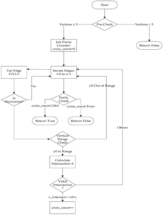
Figure 11.
The program flowchart of the constructed geofence.
The code consists of eight parts. Below is the pseudocode for each section.
- 1.
- Preprocessing Validation
| # Not a polygon if number_of_vertices < 3: |
| return False; |
- 2.
- Initialize Parity Counter
| int cross_count = 0; |
- 3.
- Iterate Through All Polygon Edges
| # Obtain current edge ViVi + 1 (closed processing) |
| for i in range(n): |
| V1 = polygon[i] |
| V2 = polygon[(i + 1) % n] |
| (x1, y1) = V1 |
| (x2, y2) = V2 |
- 4.
- Exclude Horizontal Edges
| # ε is the tolerance value (e.g., 10−10) if abs(y1 − y2) < ε: # Skip horizontal edges |
| continue |
- 5.
- Vertical Range Filtering
| # Point outside the y-range of the edge if (y0 < min(y1, y2) − ε) or (y0 > max(y1, y2) + ε): |
| continue |
- 6.
- Calculate X-Coordinate of Ray-Edge Intersection
| # Using parametric line equation: |
- 7.
- Intersection Validity Check
| # Intersection on the left side (or boundary) if x_intersect < x0 + ε; |
| cross_count += 1 |
- 8.
- Parity Check
| # Odd = inside, even = outside return (cross_count % 2) == 1; |
6. Experimental Validation of System Reliability and Safety Control Strategies
To systematically evaluate the reliability of the hardware/software co-design and the rationality of safety control strategies, comprehensive experiments were conducted to assess the system’s capabilities in autonomous decision-making, real-time responsiveness, and dynamic adaptation. The geofence functionality, a core component of the autonomous safety control strategy, was specifically validated through targeted testing.
6.1. Test Environment Configuration
The experimental setup is illustrated in Figure 12.
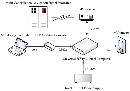
Figure 12.
Experimental setup.
Key components included the following:
- Direct current power supply: A Gwinstek PSW30-36 provided DC power (18–32 V and 28 V used in tests) to the universal safety control computer.
- Monitoring computer: A HUAWEI MateBook 14s 2023 equipped with custom monitoring software was connected via a MOXA UC-2100 USB-to-RS422 converter.
This software enabled the following:
- Manual issuance of safety control commands.
- Configuration of no-fly zones (geofences).
- Real-time visualization of system status (actuator feedback, operational duration, and active module in the triple-module redundancy (TMR) system).
- 3.
- Multimeter: A FLUKE F116C monitored output voltage levels. A high-level signal (28 V) was triggered only when safety control conditions were met and validated by triple-module consensus.
- 4.
- Global navigation satellite system (GNSS) simulation environment:
- A GNS-8340 Multi-Constellation Navigation Signal Simulator generated synthetic GNSS RF signals.
- An XD2P230YX GPS receiver converted simulated signals into digital latitude/longitude data, transmitted via RS232 to the safety control computer.
The test equipment and corresponding models used in the experiments are listed in Table 3:
Table 3.
Test equipment and corresponding models.
6.2. Real-Time Responsiveness Testing
To validate the real-time responsiveness of the universal safety control computer, the following experimental procedure was rigorously executed under the nominal operating conditions of the triple-module redundancy (TMR) system:
6.2.1. Test Configuration
Device Initialization:
The TMR system (Modules A, B, and C) was initialized with validated firmware to ensure synchronized operation.
Actuator Groups:
Twelve independent actuator groups were connected, each representing a critical safety mechanism.
Monitoring Setup:
A timestamp-synchronized monitoring computer recorded the following:
Command transmission time (): when a safety command was manually issued.
Actuator response time (): when the actuator was physically triggered (detected via digital feedback).
6.2.2. Experimental Procedure
Command Issuance:
- Operators sent safety control commands through the monitoring software.
- Each command targeted a specific actuator group.
Data Collection:
- For each actuator group, five consecutive trials were performed to account for operational variability.
- Latency () was calculated as follows:
Threshold Validation:
- The design requirement mandated .
- Failures were defined as or inconsistent TMR voting results.
6.2.3. Statistical Analysis
Dataset: 12 actuator groups × 5 trials = 60 data points.
Key Metrics:
- Maximum latency: 499 ms.
- Average latency: 410 ms.
- Standard deviation: ±42 ms.
The recorded latency time parameters are presented in Table 4
Table 4.
Real-time latency of actuator groups in safety control testing.
6.2.4. Results and Discussion
Design compliance: all trials met the criterion, with the worst-case latency at 49.9% of the threshold.
Deterministic behavior: latency variations (±42 ms) primarily arose from the following:
- Communication jitter: RS422 serial protocol timing tolerances.
- Actuator mechanical delay: physical response time of pyrotechnic cutters’ actuation relay (typically 20–50 ms).
6.3. Fault Handling and Dynamic Adaptation Testing
To validate the system’s fault tolerance and autonomous decision-making capabilities under module failures, a progressive fault injection experiment was conducted. The test aimed to verify the following:
- Automatic failover within <16 s when a module fails.
- Uninterrupted safety command execution during failover.
6.3.1. Test Procedure
Baseline condition:
- Step 1: All three modules (A, B, C) operated normally.
- Fault injection:
- Step 2: Erase the firmware of Module A to simulate failure.
- Step 3: Erase the firmware of Module B after Step 1.
- Step 4: Restore all modules, then erase Module C.
- Step 5: Erase Module A again to test dual-fault recovery.
Data recorded:
- Active module status (green: normal; red: fault).
- Failover time (time from fault detection to backup activation).
- Command execution time (latency between command issuance and actuator response).
6.3.2. Test Results
The active module switching process across test steps, as displayed by the monitoring software, is illustrated in Figure 13.
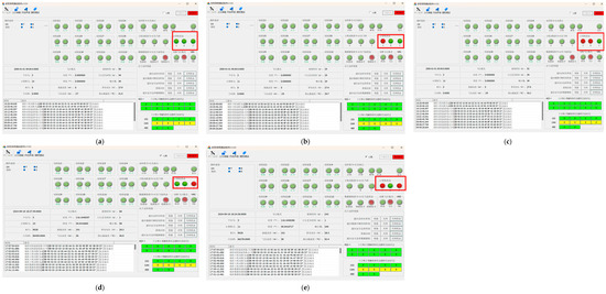
Figure 13.
Test Results Displayed by the Monitoring Software (a) Step 1; (b) Step 2; (c) Step 1; (d) Step 4; (e) Step 5.
The integrated test log in Table 5 was compiled through the synchronization of (a) active module switching processes across test steps, as visualized by the monitoring interface, and (b) background computational datasets, with timestamped parameter validation.
Table 5.
Fault handling and dynamic adaptation testing integrated test log.
6.3.3. Results and Discussion
- 1.
- Automatic Failover Mechanism
- Failover Time: The system consistently achieved module switching to a healthy unit within <16 s (maximum observed: 15.864 s) upon fault detection.
- Autonomy: Transitions occurred without human intervention, driven by the triple modular redundancy (TMR) voting algorithm.
- 2.
- Command Execution Stability
- Latency Consistency: Safety command execution times remained stable at 0.348–0.467 s during failover, demonstrating no degradation compared to normal operation (baseline <1 s). This confirms the system’s ability to maintain real-time control under fault conditions.
- Under conditions of triple modular redundancy (TMR) voting input inconsistencies, the system remained a fault-free actuator operation, thereby conclusively validating the robustness of the redundancy management algorithm.
- 3.
- Dual-Fault Tolerance
Robustness Validation: In Step 5 (simultaneous failures of Modules A and C), Module B assumed control within 15.093 s, validating the architecture’s resilience in dual-failure scenarios.
- 4.
- Priority Hierarchy
Failover follows a predefined sequence (A → B → C) to prioritize module availability.
6.4. Geofence Functional Validation
To verify the geospatial containment efficacy, we conducted rigorous validation through the following experimental framework.
6.4.1. Geofence Definition
A 12-vertex polygonal boundary was established using geographically distributed coordinates across Central and Eastern China (Table 6).
Table 6.
Geofence definition.
The polygon formed by these 12 coordinate points on the map is shown in Figure 14.
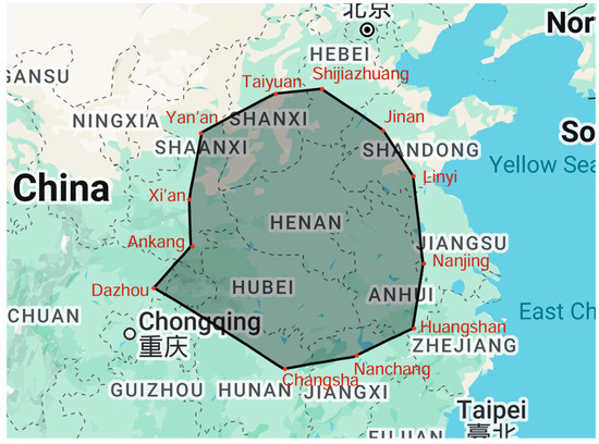
Figure 14.
Geofence coordinates.
6.4.2. Test Case Selection
Select two test cities on the map: Luoyang located within the closed space of the geofence, and Beijing located outside the geofence.
6.4.3. Instrumentation Setup
- Input the above 12 coordinate points (latitude and longitude data) into the safety control computer.
- Connect a GPS receiver to the safety control computer.
- Use a Multi-Constellation Navigation Signal Simulator to inject test coordinates (Figure 15).
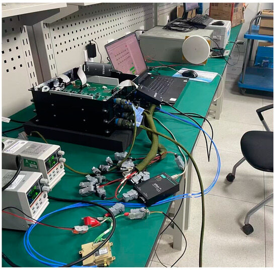 Figure 15. Hardware-in-loop test architecture with GNSS signal injection.
6.4.4. Results and Discussion
- Beijing (Outside Geofence):
Multi-Constellation Navigation Signal Simulator sends coordinates (116.333333° E, 39.933333° N).
Safety control computer detects boundary breach and triggers emergency protocols.
- Luoyang (Inside Geofence):
Multi-Constellation Navigation Signal Simulator sends coordinates (112.400000° E, 34.400000° N).
Safety control computer confirms location within bounds; no action taken.
The test results are shown in Table 7.
Table 7.
Test results.
7. Conclusions
This research significantly advances aerostat safety control systems through a modular design, redundancy mechanisms, and hierarchical threat–response strategies, offering a foundational framework for autonomous operations. While these contributions mark theoretical and engineering progress, a reflective discussion on the study’s limitations, underlying assumptions, and deployment risks is critical to contextualize its real-world applicability.
Key contributions:
- Theoretical contribution: the proposed functional decoupling framework establishes the first functional decoupling framework specifically for aerostat safety computers, addressing the critical limitation of platform-specific fragmentation in existing solutions.
- Engineering practice: it proposes a generalizable architecture for aerostat safety control computers by balancing reliability and economic feasibility.
- Summary of aerostat safety control strategies: it summarizes common safety control strategies for aerostats. It combines remote commands with autonomous decision-making to achieve hierarchical threat responses.
Limitations of the Current Study:
- Pending Flight Experiments Due to Airspace Restrictions:
Although the system design has been finalized, full-scale flight experiments remain unimplemented due to regulatory airspace constraints. Consequently, potential challenges in actual flight operations (e.g., unexpected turbulence, electromagnetic interference, or sensor degradation) have not yet been empirically validated.
- 2.
- Uncertainty in Real-World Operational Scenarios
The current validation focuses on controlled laboratory environments and preprogrammed failure modes. Key real-world stressors—such as GPS spoofing, signal noise, and multi-agent coordination conflicts—were not systematically incorporated into the testing framework.
- 3.
- Limitations in the testing of safety control strategies
While the functional validation of safety mechanisms (e.g., geofencing) was conducted, critical performance metrics—boundary conditions and error margins—were not quantitatively assessed.
Future Directions:
- Perform comprehensive and rigorous testing of quantitative metrics for safety control strategies under diverse interference and error conditions. Conduct full-scale flight tests to verify system performance in real-world environments (e.g., extreme weather and electromagnetic interference).
- Expand deployment in commercial logistics, emergency response, and environmental monitoring.
This study provides a vital blueprint for aerostat safety systems, yet its translational success hinges on confronting limitations transparently. The absence of real-world validation and quantitative safety margins underscores the need for humility in claiming robustness. By prioritizing rigorous testing, re-evaluating cost-reliability trade-offs, and fostering interdisciplinary collaboration, this framework can evolve from a promising prototype to a trusted, field-ready solution. Ultimately, the journey toward next-generation aerostat autonomy demands not just technical innovation but also a commitment to addressing the hidden risks embedded in assumptions and untested scenarios.
Author Contributions
Conceptualization, Y.H. and Z.L.; Methodology, Y.H., Z.L. and Y.Y.; Software, Q.D.; Validation, Y.H.; Formal analysis, Y.Y.; Investigation, Y.H.; Data curation, Q.D.; Writing—original draft, Y.H.; Writing—review & editing, Y.H.; Visualization, Z.L. and Q.D.; Supervision, B.W.; Project administration, Y.H.; Funding acquisition, Y.H. All authors have read and agreed to the published version of the manuscript.
Funding
This research was funded by the National Key Research and Development Program of China, Collaborative Observation Mission Planning for Terrestrial and Space Integration: 2022YFB390180501.
Data Availability Statement
The data presented in this study are available on request from the corresponding author.
Conflicts of Interest
The authors declare no conflict of interest.
Correction Statement
This article has been republished with a minor correction to the Funding statement. This change does not affect the scientific content of the article.
References
- Wang, Y.; Zhang, C.; Ge, T.; Pan, M. Efficient data transmission scheme for massive high altitude platform networks. IEEE Trans. Netw. Sci. Eng. 2024, 11, 2837–2848. [Google Scholar] [CrossRef]
- Wang, Z.; Zhang, D.; Qiao, T.; Chen, C.; Cheng, H. Influence of horizontal wind on high-altitude balloon system dynamics. Adv. Space Res. 2025, 75, 823–836. [Google Scholar] [CrossRef]
- Boschetti, N.; Slay, J.; Plotnek, J.; Karabulut Kurt, G.; Falco, G. An overview of high altitude platform stations (haps) systems, haps vehicle architecture, and haps cybersecurity. ASCEND 2023, 2023, 4800. [Google Scholar]
- Williams, J.; Barney, C.; Becker, Z.; Davis, J.; Major, C.; LaMeres, B. RadPC@ Scale: A Novel Approach to the RadPC Single Event Upset Mitigation Strategy. In Proceedings of the 2022 IEEE Aerospace Conference (AERO), Big Sky, MT, USA, 5–12 March 2022; pp. 1–7. [Google Scholar]
- Yost, B.; Weston, S. State-of-the-Art Small Spacecraft Technology; NASA: Washington, DC, USA, 2024. [Google Scholar]
- Zhang, Y.; Yang, Y.; Zhang, Y.; Wu, L.; Guo, Z. Research on Triplex Redundant Flight Control System Based on M1394B Bus. Aerospace 2024, 11, 909. [Google Scholar] [CrossRef]
- Nöldeke, P.; Lukić, B.; Durak, U. FPGA-Based Fault Tolerance Framework for Avionics Systems. In Proceedings of the 2024 AIAA DATC/IEEE 43rd Digital Avionics Systems Conference (DASC), San Diego, CA, USA, 29 September–3 October 2024; pp. 1–7. [Google Scholar]
- Zheng, B.; Zhu, M.; Guo, X.; Ou, J.; Yuan, J. Path planning of stratospheric airship in dynamic wind field based on deep reinforcement learning. Aerosp. Sci. Technol. 2024, 150, 109173. [Google Scholar] [CrossRef]
- Liu, W.; Wu, M.; Wan, G.; Xu, M. Digital twin of space environment: Development, challenges, applications, and future outlook. Remote Sens. 2024, 16, 3023. [Google Scholar] [CrossRef]
- Encyclopedia Britannica Editors. Airship. Encyclopedia Britannica. Available online: https://www.britannica.com/technology/airship (accessed on 11 February 2023).
- Plumley, L. Innovation for the Air: A Brief History of Worldwide Aviation; University of Nebraska: Lincoln, NE, USA, 2023. [Google Scholar]
- Lee, M.; Smith, S.; Androulakakis, S. The high altitude lighter than air airship efforts at the US army space and missile defense command/army forces strategic command. In Proceedings of the 18th AIAA Lighter-Than-Air Systems Technology Conference, Seattle, WA, USA, 4–7 May 2009. [Google Scholar]
- Zhang, Y.; Wang, Z.; Huang, T. Event-based Construction Method of Stratospheric Airship Test Scenario. J. Phys. Conf. Ser. 2023, 2569, 012041. [Google Scholar] [CrossRef]
- Albeaino, G.; Gheisari, M.; Franz, B.W. A systematic review of unmanned aerial vehicle application areas and technologies in the AEC domain. J. Inf. Technol. Constr. 2019, 24, 381. [Google Scholar]
- Shao, X.; Zhang, F.; Liu, J.; Zhang, Q. Finite-Time Learning-Based Optimal Elliptical Encircling Control for UAVs With Prescribed Constraints. IEEE Trans. Intell. Transp. Syst. 2025. early access. [Google Scholar] [CrossRef]
- Li, S.; Shao, X.; Wang, H.; Liu, J.; Zhang, Q. Adaptive Critic Attitude Learning Control for Hypersonic Morphing Vehicles without Backstepping. IEEE Trans. Aerosp. Electron. Syst. 2025. early access. [Google Scholar] [CrossRef]
- Zhang, F.; Shao, X.; Zhang, W. Cooperative fusion localization of a nonstationary target for multiple uavs without gps. IEEE Syst. J. 2024. early access. [Google Scholar] [CrossRef]
- Bi, X.; Qin, R.; Wu, D.; Zheng, S.; Zhao, J. One step forward for smart chemical process fault detection and diagnosis. Comput. Chem. Eng. 2022, 164, 107884. [Google Scholar] [CrossRef]
- Wang, Y.; Chung, S.H. Artificial intelligence in safety-critical systems: A systematic review. Ind. Manag. Data Syst. 2022, 122, 442–470. [Google Scholar] [CrossRef]
- Zhang, F.; Chen, M.; Zhu, Y.; Zhang, K.; Li, Q. A review of fault diagnosis, status prediction, and evaluation technology for wind turbines. Energies 2023, 16, 1125. [Google Scholar] [CrossRef]
- Zhu, C.; Bao, L.; Zheng, B.; Qian, J.; Cai, Y.; Wang, B. Motor Dynamic Loading and Comprehensive Test System Based on FPGA and MCU. Electronics 2022, 11, 1317. [Google Scholar] [CrossRef]
- Balasubramanian, P.; Maskell, D.; Mastorakis, N. Majority and minority voted redundancy scheme for safety-critical applications with error/no-error signaling logic. Electronics 2018, 7, 272. [Google Scholar] [CrossRef]
- Xu, H.; Zhang, B.; Pan, C.; Li, K. Energy-efficient triple modular redundancy scheduling on heterogeneous multi-core real-time systems. J. Parallel Distrib. Comput. 2024, 191, 104915. [Google Scholar] [CrossRef]
- Barbirotta, M.; Cheikh, A.; Mastrandrea, A.; Menichelli, F.; Ottavi, M.; Olivieri, M. Evaluation of dynamic triple modular redundancy in an interleaved-multi-threading risc-v core. J. Low Power Electron. Appl. 2022, 13, 2. [Google Scholar] [CrossRef]
- Qiang, T. Engineering design of electronic fence system based on intelligent monitoring and wireless local area network. Alex. Eng. J. 2022, 61, 2959–2969. [Google Scholar] [CrossRef]
- Kumar, G.N.; Bangi, M. An extension to winding number and point-in-polygon algorithm. IFAC-Pap. 2018, 51, 548–553. [Google Scholar] [CrossRef]
- Avis, D.; Bremner, D. How good are convex hull algorithms? In Proceedings of the Eleventh Annual Symposium on Computational Geometry, Vancouver, BC, Canada, 5–7 June 1995; pp. 20–28. [Google Scholar]
- Ize, T.; Wald, I.; Parker, S.G. Ray tracing with the BSP tree. In Proceedings of the 2008 IEEE Symposium on Interactive Ray Tracing, Los Angeles, CA, USA, 9–10 August 2008; pp. 159–166. [Google Scholar]
- Muminov, A.; Na, D.; Lee, C.; Kang, H.; Jeon, H.S. Monitoring and controlling behaviors of livestock using virtual fences. J. Theor. Appl. Inf. Technol 2019, 97, 4909–4920. [Google Scholar]
- Fu, Q.; Liang, X.; Zhang, J.; Qi, D.; Zhang, X. A geofence algorithm for autonomous flight unmanned aircraft system. In Proceedings of the 2019 International Conference on Communications, Information System and Computer Engineering (CISCE), Haikou, China, 5–7 July 2019; pp. 65–69. [Google Scholar]
- Diatta, D.N.; Rouillier, F.; Roy, M.-F. On the computation of the topology of plane curves. In Proceedings of the 39th International Symposium on Symbolic and Algebraic Computation, Kobe, Japan, 23–25 July 2014; pp. 130–137. [Google Scholar]
Disclaimer/Publisher’s Note: The statements, opinions and data contained in all publications are solely those of the individual author(s) and contributor(s) and not of MDPI and/or the editor(s). MDPI and/or the editor(s) disclaim responsibility for any injury to people or property resulting from any ideas, methods, instructions or products referred to in the content. |
© 2025 by the authors. Licensee MDPI, Basel, Switzerland. This article is an open access article distributed under the terms and conditions of the Creative Commons Attribution (CC BY) license (https://creativecommons.org/licenses/by/4.0/).