
Application of Line-Start Permanent-Magnet Synchronous Motor in Converter Drive System with Increased Safety Level


Abstract
1. Introduction
2. LSPMSM Mathematical Model
- are the stator and rotor resistances, respectively.
- L′ldr and L′lqr are the rotor inductance losses;
- Lmd and Lmq are the mutual inductances in d-q coordinates;
- Lsd and Lsq are the stator inductances in d-q coordinates.
- Using the flux loss values and inductance parameters, the stator ids, iqs and rotor currents i′dr and i′qr can be expressed as follows:
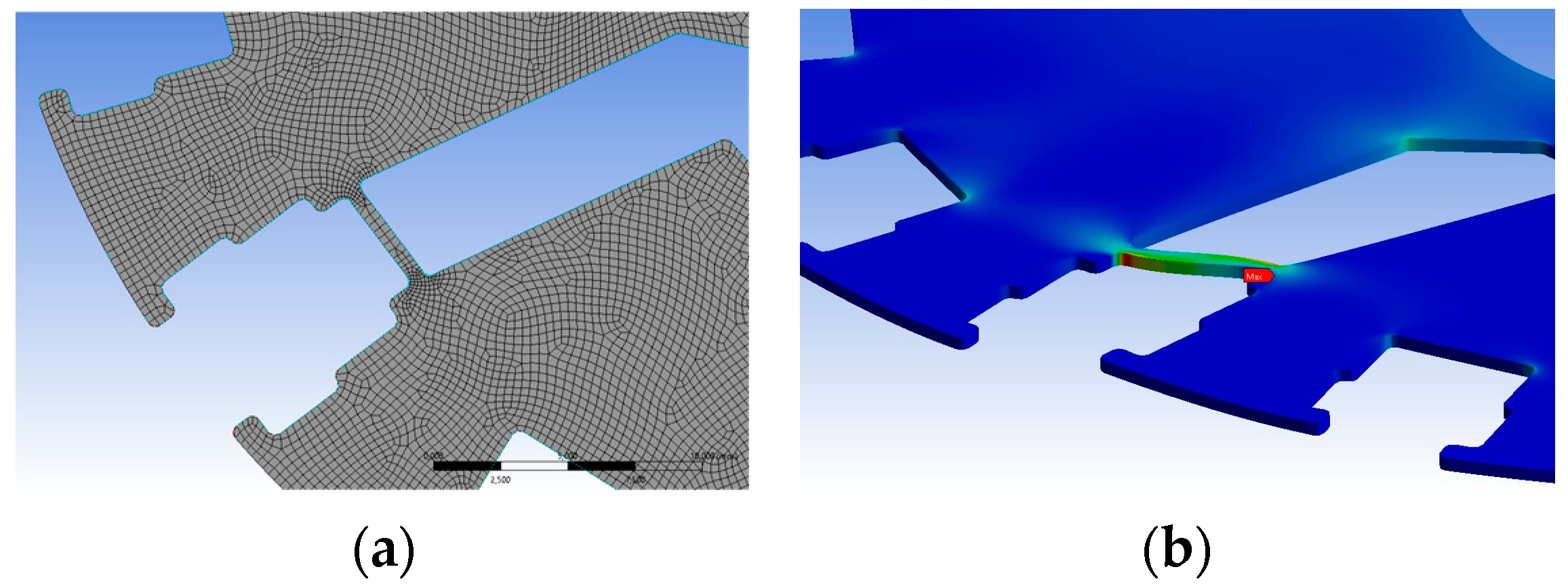
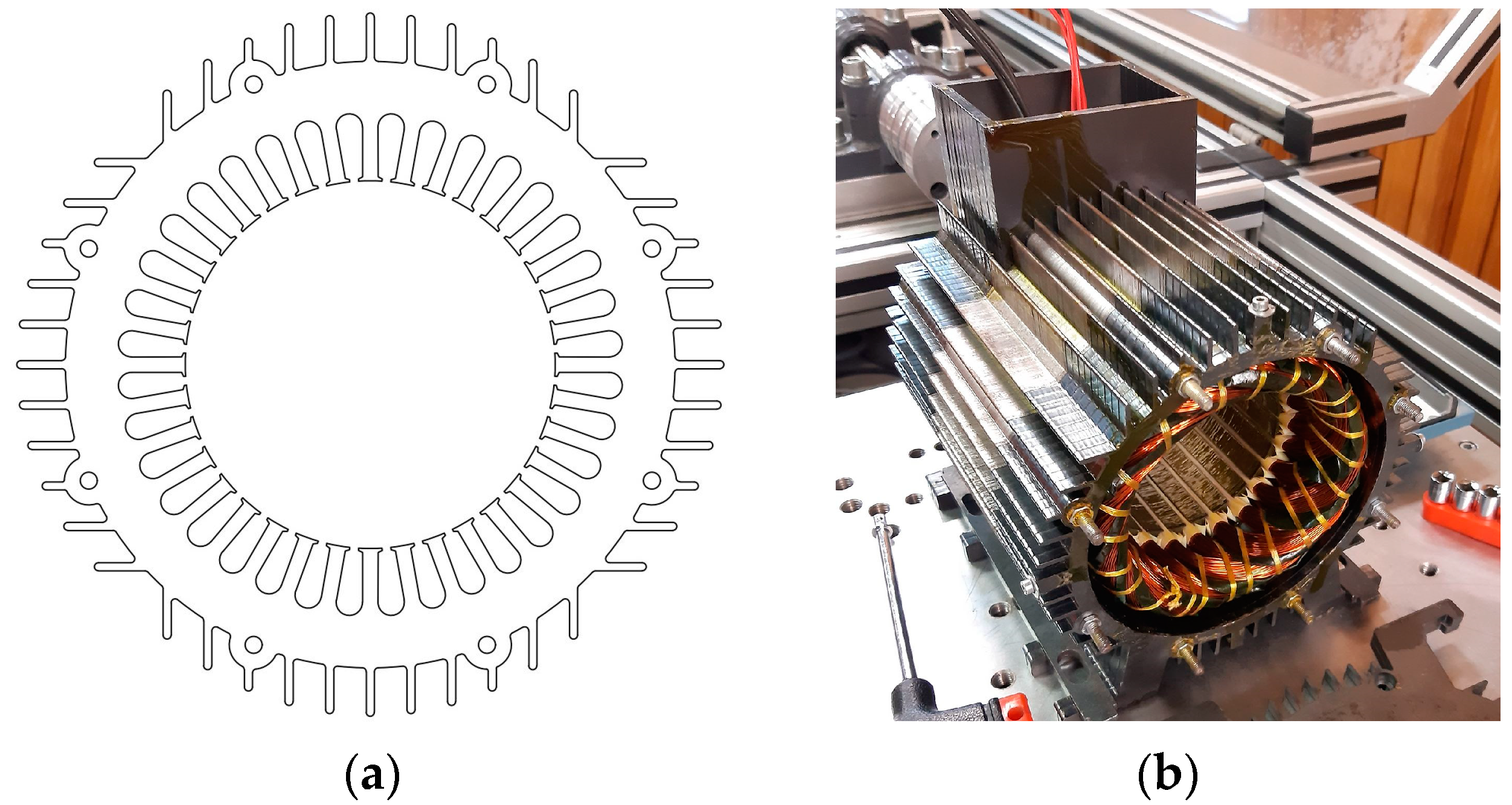
3. Induced-Pole LSPMSM Design
4. Induced-Pole LSPMSM Direct-on-Line Supply
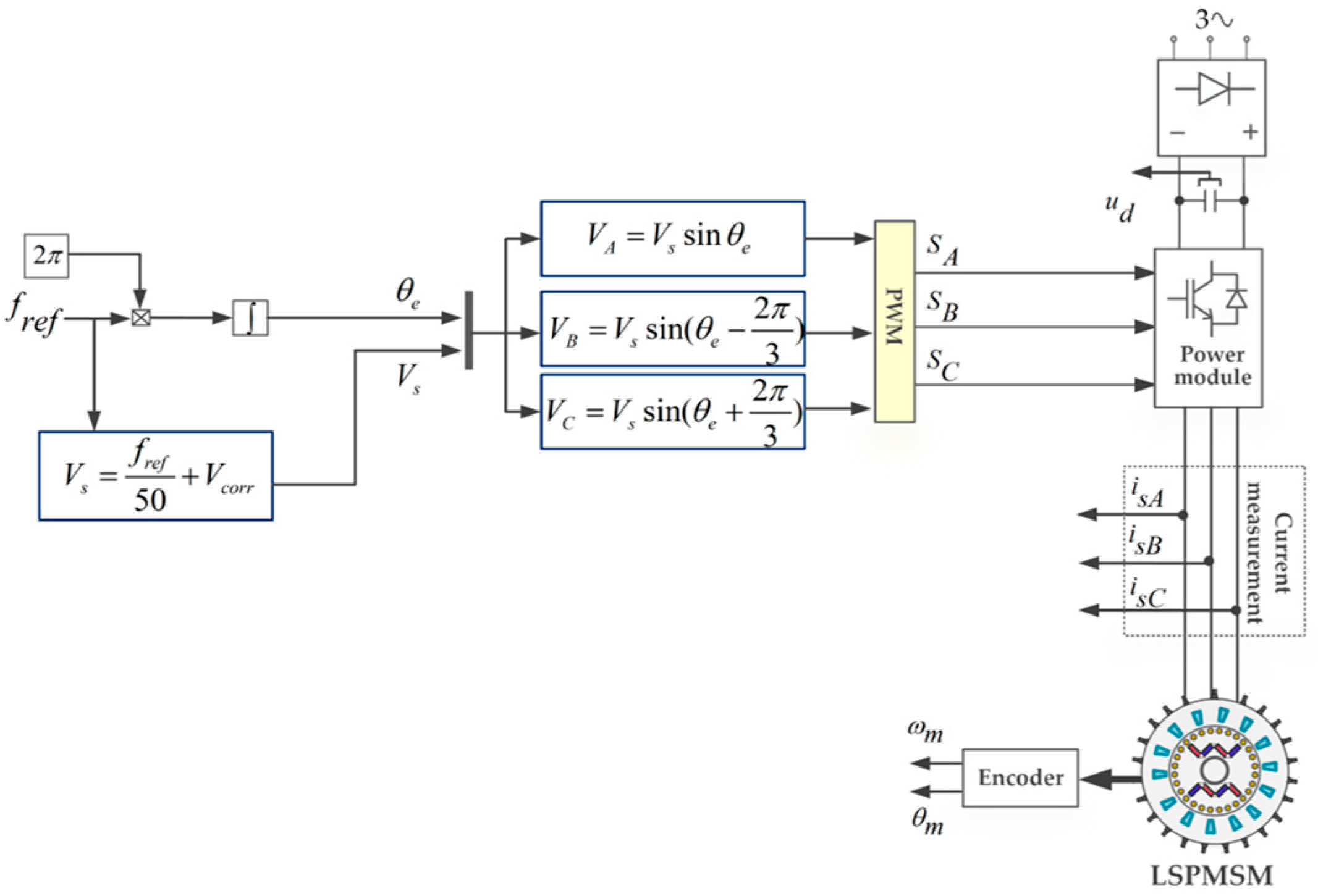
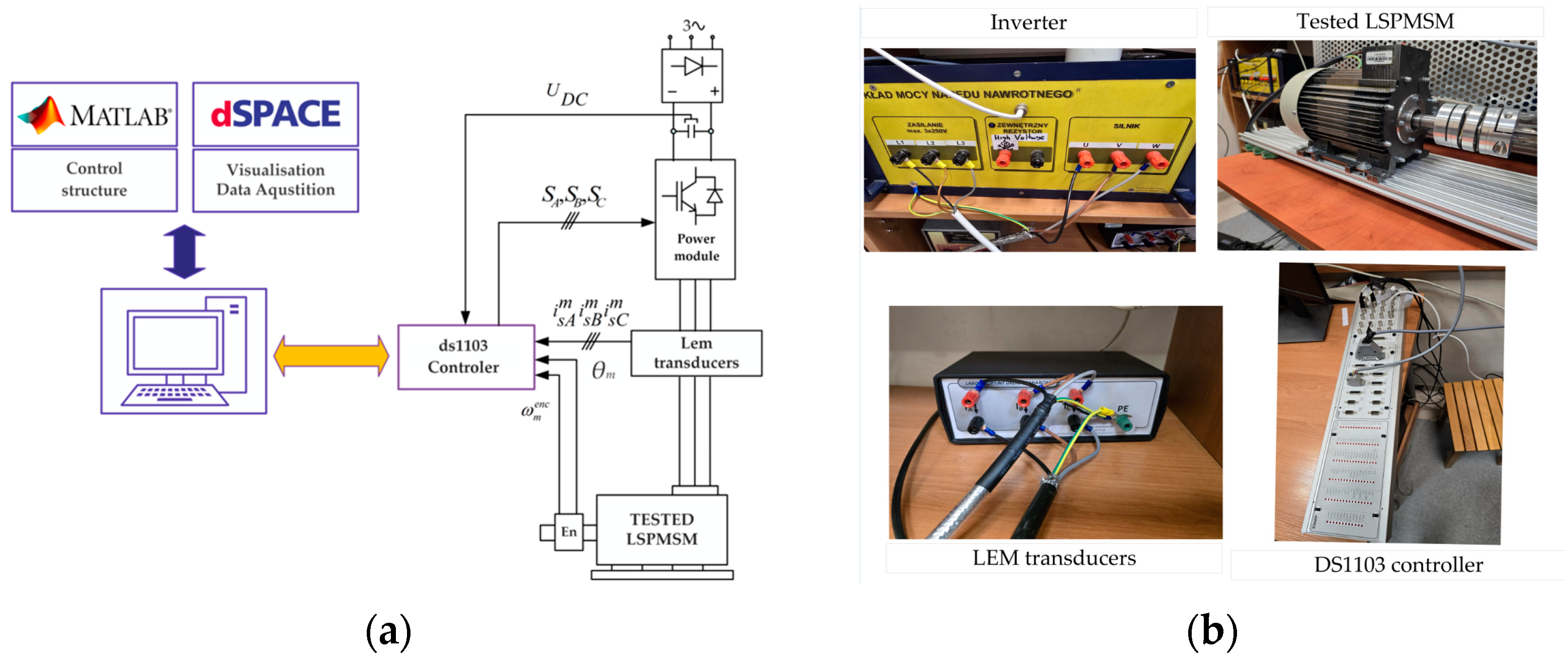
5. Scalar Motor Control
6. Conclusions
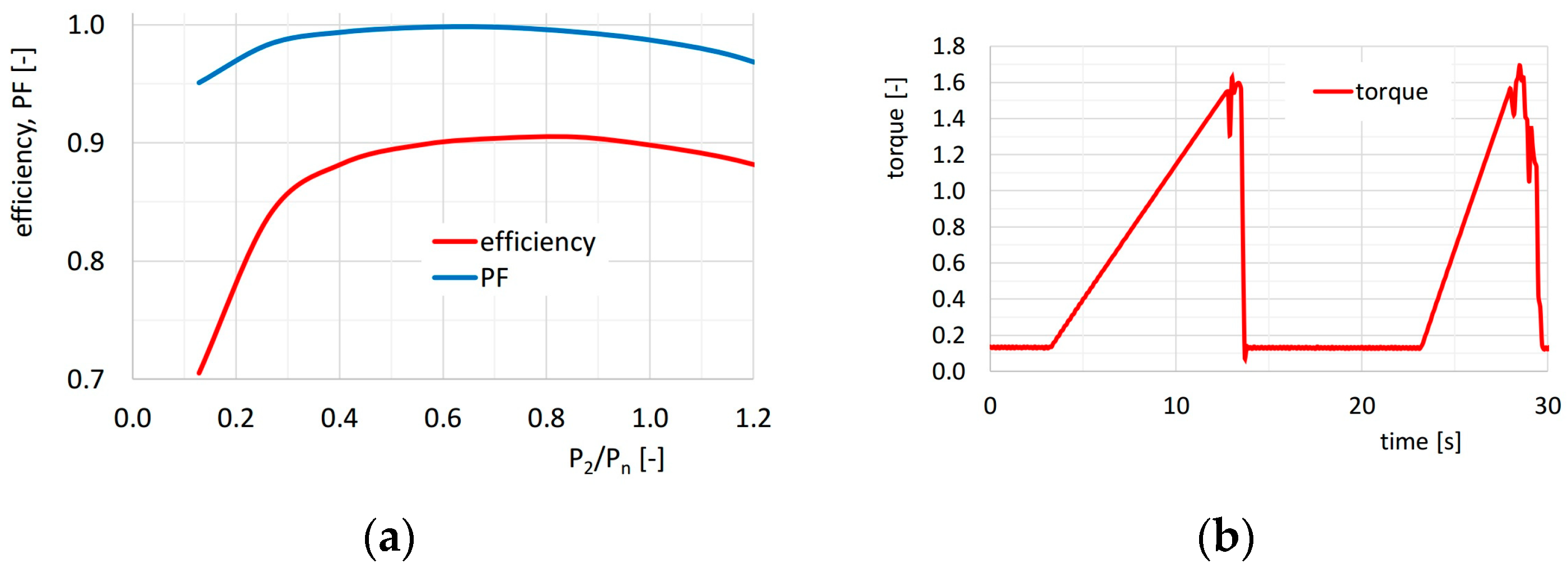
- Power factor—0.89;
- Motor efficiency—90%;
- Maximum torque ratio—1.6.
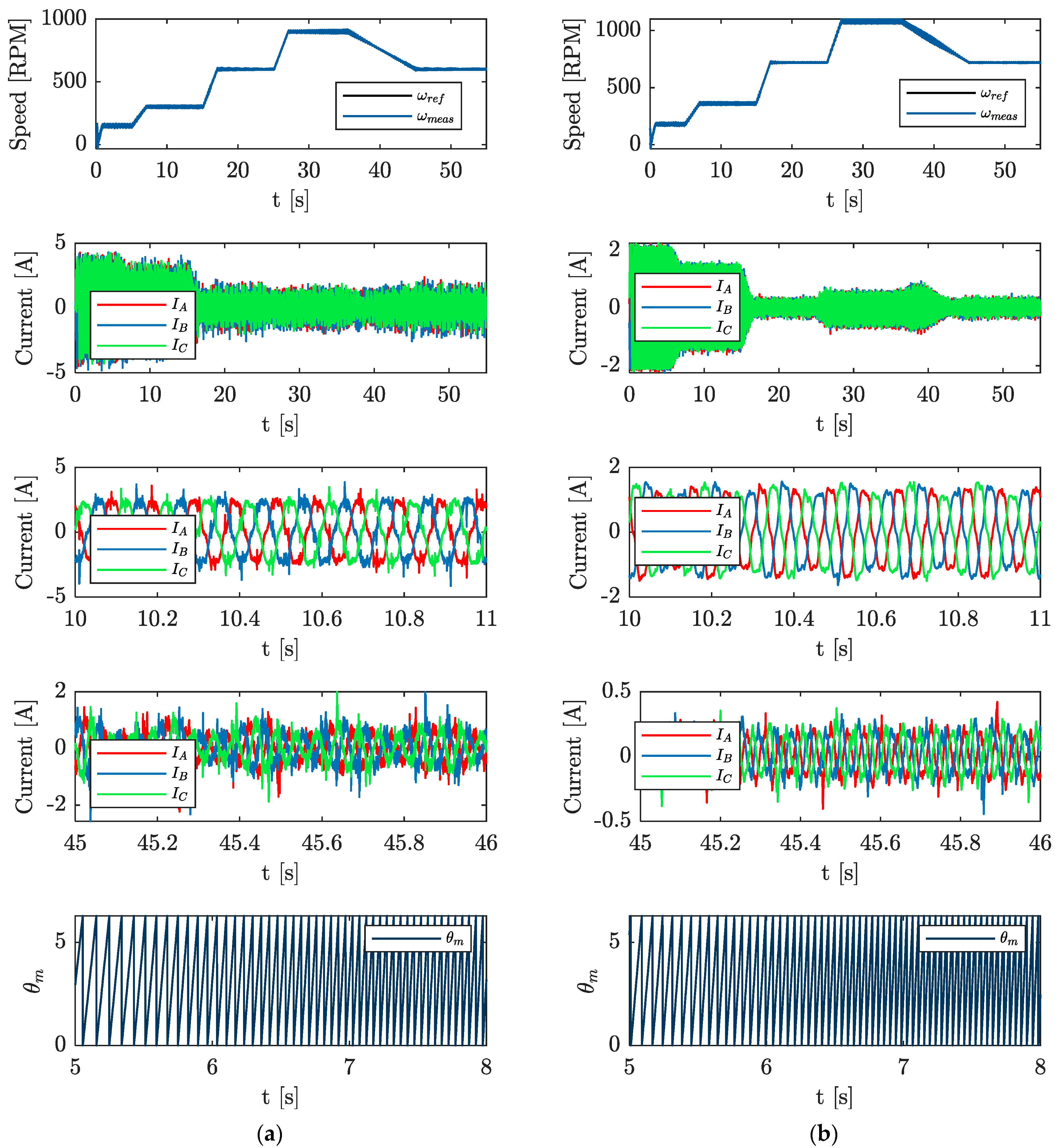
- Speed regulation was smooth, and the speed profiles had a satisfactory shape.
- The values of the current THD coefficient in each phase for the tested cases did not exceed 3%.
Author Contributions
Funding
Institutional Review Board Statement
Informed Consent Statement
Data Availability Statement
Conflicts of Interest
References
- Zhang, J.; Zhan, W.; Ehsani, M. Diagnosis and Fault-Tolerant Control of Permanent Magnet Synchronous Motors with Interturn Short-Circuit Fault. IEEE Trans. Control. Syst. Technol. 2023, 31, 1909–1916. [Google Scholar] [CrossRef]
- Novak, Z. Confidence Weighted Learning Entropy for Fault-Tolerant Control of a PMSM With a High-Resolution Hall Encoder. IEEE Trans. Ind. Electron. 2024, 71, 5176–5186. [Google Scholar] [CrossRef]
- Li, L.; Ding, S.X.; Luo, H.; Peng, K.; Yang, Y. Performance-Based Fault-Tolerant Control Approaches for Industrial Processes with Multiplicative Faults. IEEE Trans. Ind. Inform. 2019, 16, 4759–4768. [Google Scholar] [CrossRef]
- Wu, C.; Guo, C.; Xie, Z.; Ni, F.; Liu, H. A Signal-Based Fault Detection and Tolerance Control Method of Current Sensor for PMSM Drive. IEEE Trans. Ind. Electron. 2018, 65, 9646–9657. [Google Scholar] [CrossRef]
- Guo, C.; Wu, C.; Liu, H. A Sign Logic-Based Method of Current Sensor Fault Detection for PMSM Drivers. J. Sens. 2021, 2021, 9955348. [Google Scholar] [CrossRef]
- Li, H.; Qian, Y.; Asgarpoor, S.; Sharif, H. A Sensor Fault Isolation Scheme for Co-existence of PMSM Current Sensor and Non-sensor Imbalance Faults. In Proceedings of the 2019 IEEE Applied Power Electronics Conference and Exposition (APEC), Anaheim, CA, USA, 17–21 March 2019; pp. 2608–2613. [Google Scholar] [CrossRef]
- Bensalem, Y.; Kouzou, A.; Abbassi, R.; Jerbi, H.; Kennel, R.; Abdelrahem, M. Sliding-Mode-Based Current and Speed Sensors Fault Diagnosis for Five-Phase PMSM. Energies 2022, 15, 71. [Google Scholar] [CrossRef]
- Zhao, H.; Luo, P.; Wang, N.; Zheng, Z.; Wang, Y. Fuzzy logic control of the fault-tolerant PMSM servo system based on MRAS observer. In Proceedings of the 2018 Chinese Control and Decision Conference (CCDC), Shenyang, China, 9–11 June 2018. [Google Scholar] [CrossRef]
- Jankowska, K.; Dybkowski, M. Experimental Analysis of the Current Sensor Fault Detection Mechanism Based on Neural Networks in the PMSM Drive System. Electronics 2023, 12, 1170. [Google Scholar] [CrossRef]
- Skowron, M.; Teler, K.; Adamczyk, M.; Orlowska-Kowalska, T. Classification of Single Current Sensor Failures in Fault-Tolerant Induction Motor Drive Using Neural Network Approach. Energies 2022, 15, 6646. [Google Scholar] [CrossRef]
- Dybkowski, M.; Klimkowski, K. Artificial Neural Network Application for Current Sensors Fault Detection in the Vector Controlled Induction Motor Drive. Sensors 2019, 19, 571. [Google Scholar] [CrossRef] [PubMed]
- Wang, G.; Hao, X.; Zhao, N.; Zhang, G.; Xu, D. Current Sensor Fault-Tolerant Control Strategy for Encoderless PMSM Drives Based on Single Sliding Mode Observer. IEEE Trans. Transp. Electrif. 2020, 6, 679–689. [Google Scholar] [CrossRef]
- Foo, G.H.B.; Zhang, X.; Vilathgamuwa, D.M. A Sensor Fault Detection and Isolation Method in Interior Permanent-Magnet Synchronous Motor Drives Based on an Extended Kalman Filter. IEEE Trans. Ind. Electron. 2013, 60, 3485–3495. [Google Scholar] [CrossRef]
- Tan, L.N.; Cong, T.P.; Cong, D.P. Neural Network Observers and Sensorless Robust Optimal Control for Partially Unknown PMSM With Disturbances and Saturating Voltages. IEEE Trans. Power Electron. 2021, 36, 12045–12056. [Google Scholar] [CrossRef]
- Al-Mutayeb, Y.; Almobaied, M. Luenberger Observer-Based Speed Sensor Fault Detection of BLDC Motors. In Proceedings of the 2021 International Conference on Electric Power Engineering—Palestine (ICEPE-P), Gaza, Palestine, 23–24 March 2021; pp. 1–7. [Google Scholar] [CrossRef]
- Teler, K.; Orlowska-Kowalska, T. Analysis of the stator current prediction capabilities in induction motor drive using the LSTM network. Power Electron. Drives 2023, 8, 31–52. [Google Scholar] [CrossRef]
- Ullah, Z.; Lodhi, B.A.; Hur, J. Detection and Identification of Demagnetization and Bearing Faults in PMSM Using Transfer Learning-Based VGG. Energies 2020, 13, 3834. [Google Scholar] [CrossRef]
- Chen, Y.; Liang, S.; Li, W.; Liang, H.; Wang, C. Faults and Diagnosis Methods of Permanent Magnet Synchronous Motors: A Review. Appl. Sci. 2019, 9, 2116. [Google Scholar] [CrossRef]
- Maraaba, L.S.; Al-Hamouz, Z.M.; Abido, M.A. Mathematical Modeling, Simulation and Experimental Testing of Interior-Mount LSPMSM Under Stator Inter-Turn Fault. IEEE Trans. Energy Convers. 2019, 34, 1213–1222. [Google Scholar] [CrossRef]
- Pecho, J.; Hofmann, W. Analysis of the effects of parameter variations on the start-up characteristics of LSPMSM. In Proceedings of the 2019 21st European Conference on Power Electronics and Applications (EPE ’19 ECCE Europe), Genova, Italy, 3–5 September 2019; pp. P.1–P.10. [Google Scholar] [CrossRef]
- Yan, B.; Wang, X.; Yang, Y. Starting Performance Improvement of Line-Start Permanent-Magnet Synchronous Motor Using Composite Solid Rotor. IEEE Trans. Magn. 2018, 54, 7400504. [Google Scholar] [CrossRef]
- Bárta, J.; Toman, M.; Losak, P.; Aarniovuori, L.; Vitek, O. Line-Start Permanent Magnet Machines for Low-Power Applications. In Proceedings of the 2024 International Conference on Electrical Machines (ICEM), Torino, Italy, 1–4 September 2024; pp. 1–7. [Google Scholar] [CrossRef]
- Arshad, M.H.; El-Sayed, A.; Salem, A.; Zhao, Q.; Abido, M.A. Implications of the Sensorless Predictive Control for Line-Start Permanent Magnet Synchronous Machine. IEEE Trans. Autom. Sci. Eng. 2024, 21, 4203–4213. [Google Scholar] [CrossRef]
- Dybkowski, M.; Klimkowski, K.; Orłowska-Kowalska, T. Speed and current sensor fault-tolerant-control of the induction motor drive. In Advanced Control of Electrical Drives and Power Electronic Converters; Springer: Cham, Switzerland, 2016; pp. 141–167. [Google Scholar]
- Farooq, H.; Bracikowski, N.; La Delfa, P.; Hecquet, M. Modelling of Starting and Steady-State performance of Line Start Permanent Magnet Synchronous Motor using Reluctance Network. In Proceedings of the 2022 International Conference on Electrical Machines (ICEM), Valencia, Spain, 5–8 September 2022; pp. 226–231. [Google Scholar] [CrossRef]
- Fu, W.N.; Ho, S.L. Dynamic Demagnetization Computation of Permanent Magnet Motors Using Finite Element Method with Normal Magnetization Curves. IEEE Trans. Appl. Supercond. 2010, 20, 851–855. [Google Scholar] [CrossRef]
- Lu, W.-F.; Zhao, H.-S.; Liu, S. Demagnetization conditions comparison for line-start permanent magnet synchronous motors. In Proceedings of the 2014 17th International Conference on Electrical Machines and Systems (ICEMS), Hangzhou, China, 22–25 October 2014; pp. 48–52. [Google Scholar] [CrossRef]
- Tang, X.; Wang, X.; Li, G.; Tian, M. Demagnetization Study of Line-start Permanent Magnet Synchronous Motor Under Out-of-step and Supersynchronous Faults. In Proceedings of the IEEE 11th Conference on Industrial Electronics and Applications (ICIEA), Hefei, China, 5–7 June 2016. [Google Scholar]
- Gwozdziewicz, M.; Zawilak, J. Induced pole permanent magnet synchronous motor. In Proceedings of the 2017 International Symposium on Electrical Machines, Nałęczów, Poland, 18–21 June 2017; IEEE: Danvers, MA, USA, 2017; pp. 1–4. [Google Scholar] [CrossRef]
- Mike, K.; Baccouche, H.; Breser, S.; Jöns, T.; Löhlein, B. Simulation Time Reduction with 2.5 D FEM Analysis for Axial Flux Machines. Power Electron. Drives 2023, 8, 100–108. [Google Scholar] [CrossRef]


| Manufactured Motor Parameters | |
|---|---|
| Pn [kW] | 1.1 |
| Un [V] | 400 |
| In [A] | 1.8 |
| ηn [%] | 90 |
| PF [-] | 0.89 |
| tmax [-] | 1.6 |
| nn [RPM] | 1500 |
| THD [%] | ||||||
|---|---|---|---|---|---|---|
| [%] | ||||||
| Speed [RPM] | 450 | 600 | 600 | 800 | 800 | 1000 |
| 2.191 | 13.041 | 2.394 | 7.548 | 2.951 | 5.084 | |
| 2.899 | 30.648 | 2.763 | 7.771 | 2.793 | 4.967 | |
| 2.284 | 9.330 | 2.896 | 7.938 | 3.883 | 6.351 | |
Disclaimer/Publisher’s Note: The statements, opinions and data contained in all publications are solely those of the individual author(s) and contributor(s) and not of MDPI and/or the editor(s). MDPI and/or the editor(s) disclaim responsibility for any injury to people or property resulting from any ideas, methods, instructions or products referred to in the content. |
© 2025 by the authors. Licensee MDPI, Basel, Switzerland. This article is an open access article distributed under the terms and conditions of the Creative Commons Attribution (CC BY) license (https://creativecommons.org/licenses/by/4.0/).
Share and Cite
Jankowska, K.; Gwoździewicz, M.; Dybkowski, M. Application of Line-Start Permanent-Magnet Synchronous Motor in Converter Drive System with Increased Safety Level. Electronics 2025, 14, 1787. https://doi.org/10.3390/electronics14091787
Jankowska K, Gwoździewicz M, Dybkowski M. Application of Line-Start Permanent-Magnet Synchronous Motor in Converter Drive System with Increased Safety Level. Electronics. 2025; 14(9):1787. https://doi.org/10.3390/electronics14091787
Chicago/Turabian StyleJankowska, Kamila, Maciej Gwoździewicz, and Mateusz Dybkowski. 2025. "Application of Line-Start Permanent-Magnet Synchronous Motor in Converter Drive System with Increased Safety Level" Electronics 14, no. 9: 1787. https://doi.org/10.3390/electronics14091787
APA StyleJankowska, K., Gwoździewicz, M., & Dybkowski, M. (2025). Application of Line-Start Permanent-Magnet Synchronous Motor in Converter Drive System with Increased Safety Level. Electronics, 14(9), 1787. https://doi.org/10.3390/electronics14091787