Article

A Black Start Recovery Strategy for a PV-Based Energy Storage Microgrid, Considering the State of Charge of Energy Storage

1
State Grid Hebei Electric Power Reaserch Institute, Shijiazhuang 050021, China
2
State Key Laboratory of Alternate Electrical Power System with Renewable Energy Sources, North China Electric Power University, Baoding 071003, China
*
Author to whom correspondence should be addressed.
Electronics 2025, 14(9), 1696; https://doi.org/10.3390/electronics14091696
Submission received: 20 March 2025 / Revised: 16 April 2025 / Accepted: 17 April 2025 / Published: 22 April 2025

Abstract

:
To mitigate black start failures resulting from energy storage state of charge (SOC) exceeding operational limits, this study develops a restoration strategy incorporating SOC constraints. Firstly, an adaptive SOC control without bias for energy storage units is proposed to achieve SOC balance. Secondly, the maximum power point tracking (MPPT) mode for photovoltaic power generation is integrated with the load tracking mode, enabling effective tracking of load variations when the photovoltaic output is sufficient; conversely, when the photovoltaic output is inadequate, the energy storage output compensates for the shortfall, thus avoiding the SOC limit due to an insufficient remaining SOC of the energy storage, while also significantly reducing the quantity of charge and discharge cycles undergone by the energy storage units. Finally, the simulation results show that, according to the proposed control strategy for recovery, the maximum system frequency of the black start process does not exceed 50.11, and the minimum is not lower than 49.82, which are within reasonable limits. At the same time, the number of charge/discharge conversions of the three storage batteries is 12 when the PV system adopts the coordinated control of MPPT and load tracking, and the number of charge/discharge conversions of the storage batteries in the PV MPPT mode is 21. This ensures the success of the black start process and prolongs the life of the energy storage battery.

Graphical Abstract

1. Introduction

The progressive penetration of intermittent renewable energy generation into modern power systems presents significant technical challenges pertaining to dynamic stability, power quality maintenance, and operational control coordination [1], and the possibility of power outages is gradually increasing. With traditional thermal power generation, it is difficult to provide power quickly in the case of an emergency. Therefore, energy storage systems are becoming more and more important [2]. The growing integration of renewable energy sources into microgrids has introduced operational challenges due to their inherent power output variability, which particularly affects grid stability. This underscores the critical importance of developing renewable-based black start restoration strategies, which hold substantial practical value for power system resilience [3,4,5,6].
To enable renewable energy to be a black start power source, the development and implementation of a reasonable and effective microgrid black start scheme is imperative for the expeditious restoration of system power supply [7]. Compared to wind power generation, photovoltaic power generation is more suitable for microgrid applications. A photovoltaic energy storage system mainly consists of photovoltaic arrays, energy storage batteries, and an intelligent control system, which can effectively address the intermittency and fluctuation issues in photovoltaic power generation. In the process of black starting with a photovoltaic energy storage system, it is possible for the energy storage device to be subjected to either overcharging or overdischarging, which makes the voltage amplitude and frequency stability provided by the energy storage system insufficient, and leads to black start failure [8]. Investigating how to coordinate the power output between distributed generation systems to ensure the success of black starting has become a popular research direction recently.
Ref. [9] proposes an optimisation model that can reasonably allocate black start resources, taking into account the active power balance of the system, transmission switching operations, node reactive power support, and voltage constraints, and improving the scalability and computational efficiency of the model through a mixed-integer linear programming approach. The study mainly focuses on the allocation of traditional generation resources, with less discussion of distributed energy sources. In response to the problem of renewable energy involved in black starting, Ref. [10] posits a coordinated control strategy for photovoltaic and energy storage systems. However, this method does not allow for decentralised control of individual storage units within the system. Ref. [11] proposes a black start strategy for permanent magnet direct-drive wind turbines based on battery energy storage units.
Compared with the currently commonly used grid-following converter, the grid-constructing converter has synchronous voltage source characteristics, and thus has received extensive attention in recent years [12,13,14,15,16,17]. Ref. [18] proposes a VSG (virtual synchronous generator) control strategy that takes into account frequency and voltage regulation, and develops a black start operation procedure for microgrids to improve the stability of the black start process. However, coordinated control between renewable energy and other distributed power sources within the microgrid is been fully considered. Ref. [19] develops a grid-forming PV self-synchronous voltage source inverter control strategy that is capable of providing frequency and voltage support, though its potential application in black start scenarios remains unexplored. Ref. [20] proposes two effective control methods to limit the transformer excitation inrush current by correcting the reference value while keeping the voltage stable. However, the literature does not fully consider coping strategies when the storage capacity is limited. Ref. [21] proposes a black start procedure based on PV systems, verifies its feasibility in simulation, and provides a technical reference for black starting of PV microgrids. However, black starting of PV systems usually requires energy storage support, and the literature gives less consideration to energy storage systems.
In terms of practical application, the microgrid project in Zaduo County, Yushu Prefecture, Qinghai Province, China, is the country’s first project demonstrating use of a photovoltaic storage system in high-altitude regions. This system has resolved power supply issues in local non-electrified areas. The system comprises photovoltaic devices, energy storage devices, and diesel generators, featuring typical characteristics of a PV storage system.
Under sufficient sunlight conditions, the photovoltaic generation meets all load demands, while charging surplus electricity; during periods of insufficient light intensity, the photovoltaic system and energy storage system jointly supply power; and in extreme weather conditions, the diesel generator is activated to ensure critical load supply. Meanwhile, the system possesses complete black start capability, which has provided certain insights for this research.

2. Topology of PV-Based Energy Storage Microgrid Black Start System

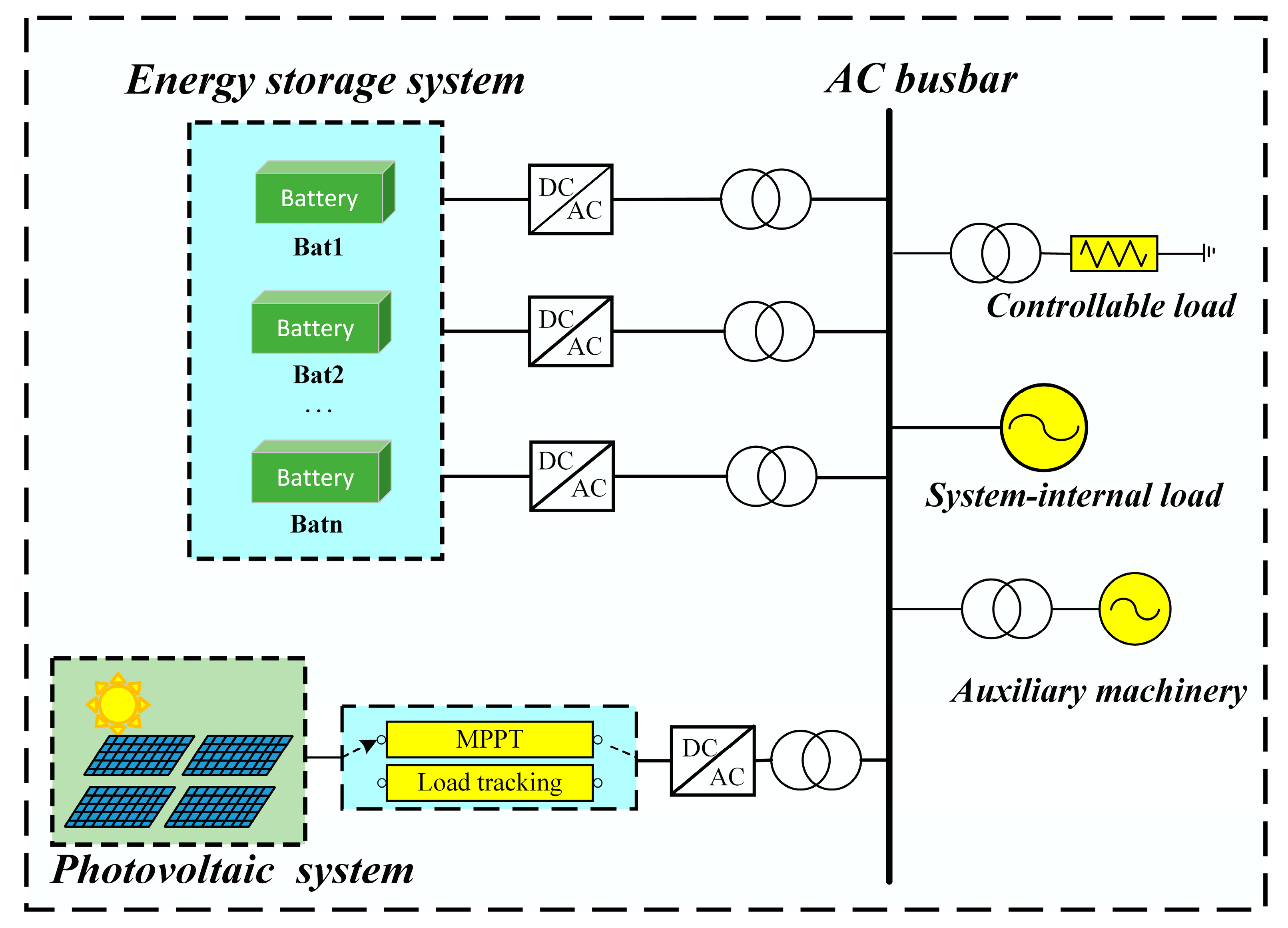
2.1. Topology of PV-Based Energy Storage Microgrid System

The topology of the PV-based energy storage microgrid is shown in Figure 1. In this topology, the energy storage device is connected to the AC bus through a DC/AC converter and transformer. Photovoltaic cells are connected to the AC bus by means of a mode switch, a DC/AC converter, and a transformer. The loads of the microgrid are then connected to the AC bus through a transformer. The PV system and the energy storage system combine to form a photovoltaic storage microgrid, which provides power during the black start process.

2.2. Main Steps Involved in Black Starting of PV-Based Energy Storage Microgrid

A black start refers to a situation whereby, after a power system is shut down due to faults, power sources in the system that have self-starting ability and a large voltage support capacity are used to help gradually start back up those power sources that do not have self-starting ability, so that the whole power grid operates again [22,23,24,25]. A PV-based energy storage microgrid black start proceeds as follows:
(1)
It is imperative that all loads in the PV-based energy storage microgrid are removed to ensure that the energy storage equipment is started in no-load environment.
(2)
The energy storage system within the power network is rigorously evaluated, with grid-forming energy storage systems exhibiting superior voltage support capabilities being prioritised as black start power sources.
(3)
The energy storage system supplies power to the busbar. Through a coordinated control strategy, the ESS maintains the bus voltage magnitude and frequency at their rated levels, ensuring a reliable synchronisation reference for distributed renewable energy sources.
(4)
The primary loads are initially connected with prioritised restoration of the critical load power supply. Subsequently, the photovoltaic system is commissioned to operate in MPPT mode.
(5)
The PV system and energy storage system jointly supply power for the auxiliary equipment, restore auxiliary machines, and expand the black start recovery surface.

3. PV-Based Energy Storage Microgrid Black Start Control Strategy

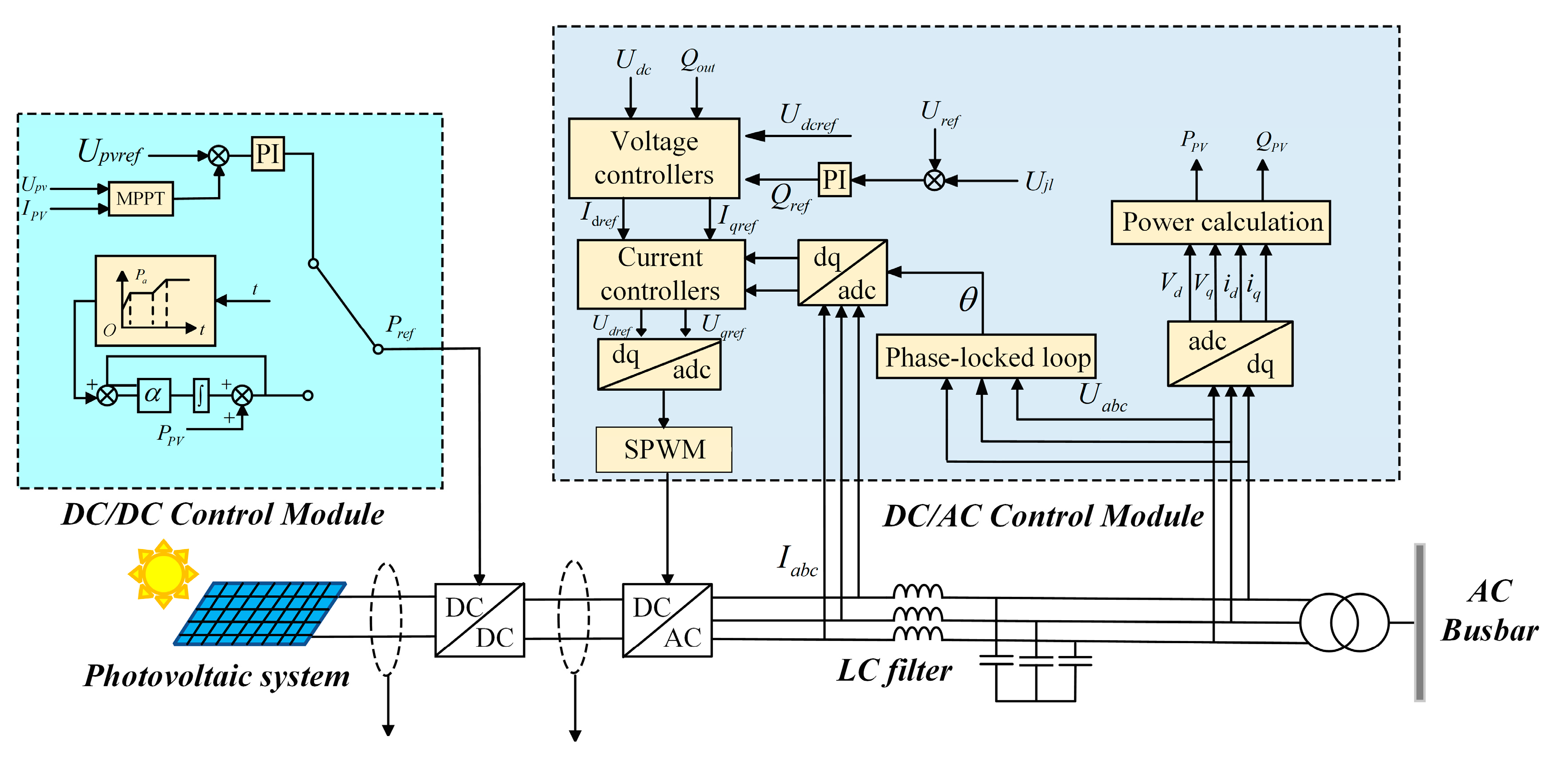
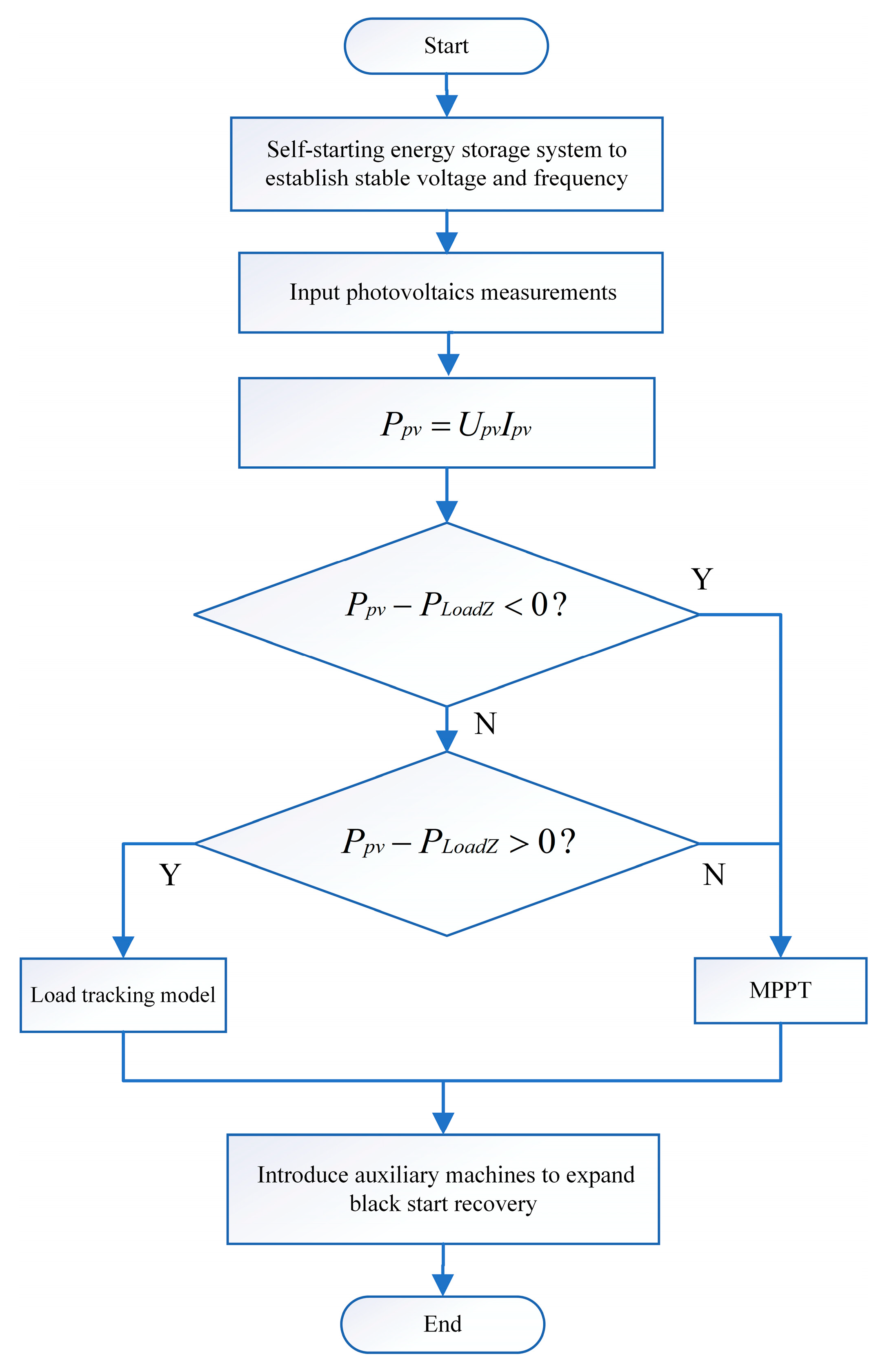
3.1. Photovoltaic System Control Strategy

The photovoltaic system model is presented in Figure 2. The PV array adopts a two-stage grid connection, which firstly passes through a DC/DC chopper for voltage amplitude conversion, and then through an inverter to convert the DC power into AC power, in order to achieve grid connection.
In the context of photovoltaic systems, the pursuit of maximum power point tracking typically entails the implementation of one of three methodologies: the perturbation observation method, the conductance increment method, and the artificial neural network method. The perturbation observation method possesses the advantages of a simple structure and low cost, which renders it suitable for the photovoltaic storage microgrid employed in this study.
In the DC/DC control module, the DC voltage of the PV array corresponding to the maximum power point is first determined using the MPPT algorithm and set as a reference signal for the voltage. This reference signal Upvref is compared with the actual DC voltage Upv, and the result of the comparison is adjusted by the voltage controller to generate the inner-loop current reference signal Ipvref, which is compared with the actual current Ipv; the current controller generates the pulse signals used for controlling the switching devices to turn on and off according to this comparison result.
The DC/AC control module employs a dual-loop control structure, featuring DC voltage and reactive power regulation in the outer loop, combined with current tracking control in the inner loop. The current reference signal for the inner-loop controller is synthesised from two distinct components. The first component derives from the DC-link voltage Udc closed-loop regulation, where the error signal between the measured DC voltage and its reference value Udcref is processed through a PI compensator to maintain stable DC bus operation at the prescribed voltage level. The second component originates from active power control, determined by normalising the maximum available power Pmax from the photovoltaic array, as computed by the MPPT algorithm, with respect to the grid-side d-axis voltage ud. This dual-feedback architecture ensures precise current tracking, while simultaneously achieving DC voltage stabilisation and optimal power extraction.

3.2. Energy Storage System Control Strategy

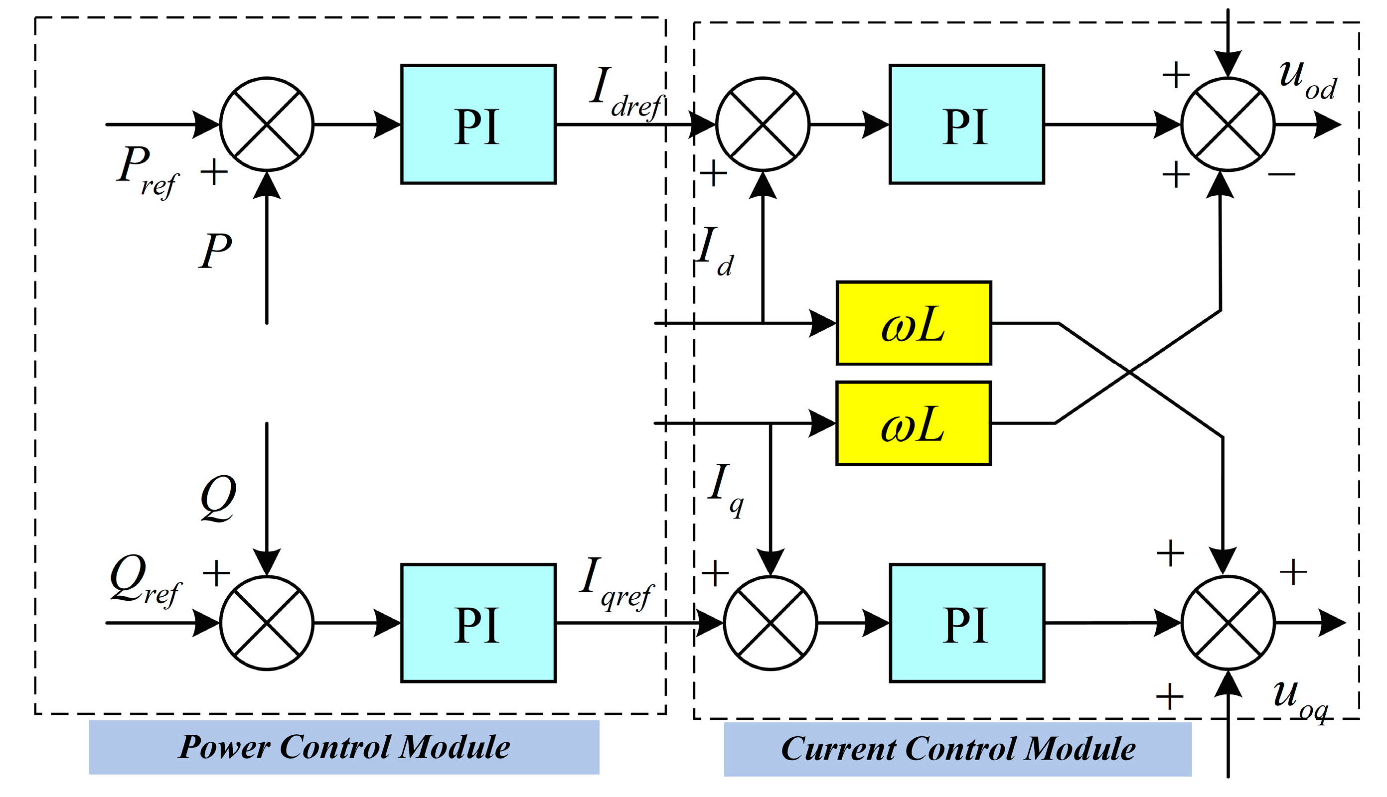
3.2.1. Conventional Constant Power Control

The constant power control (PQ control) strategy, shown in Figure 3, contains two main control modules: the power control module and the current control module. Among them, the power control module controls the output active and reactive power to be stabilised within a preset reference range, so that the converter can operate stably in the distribution network according to the required voltage and current levels. The specific control block diagram is shown in Figure 3.
However, this control strategy has problems such as poor stability and insufficient coordination in practical applications. At the same time, the PQ-controlled power generation system can only output according to a given power command, and other distributed power generation systems need to be connected in parallel.

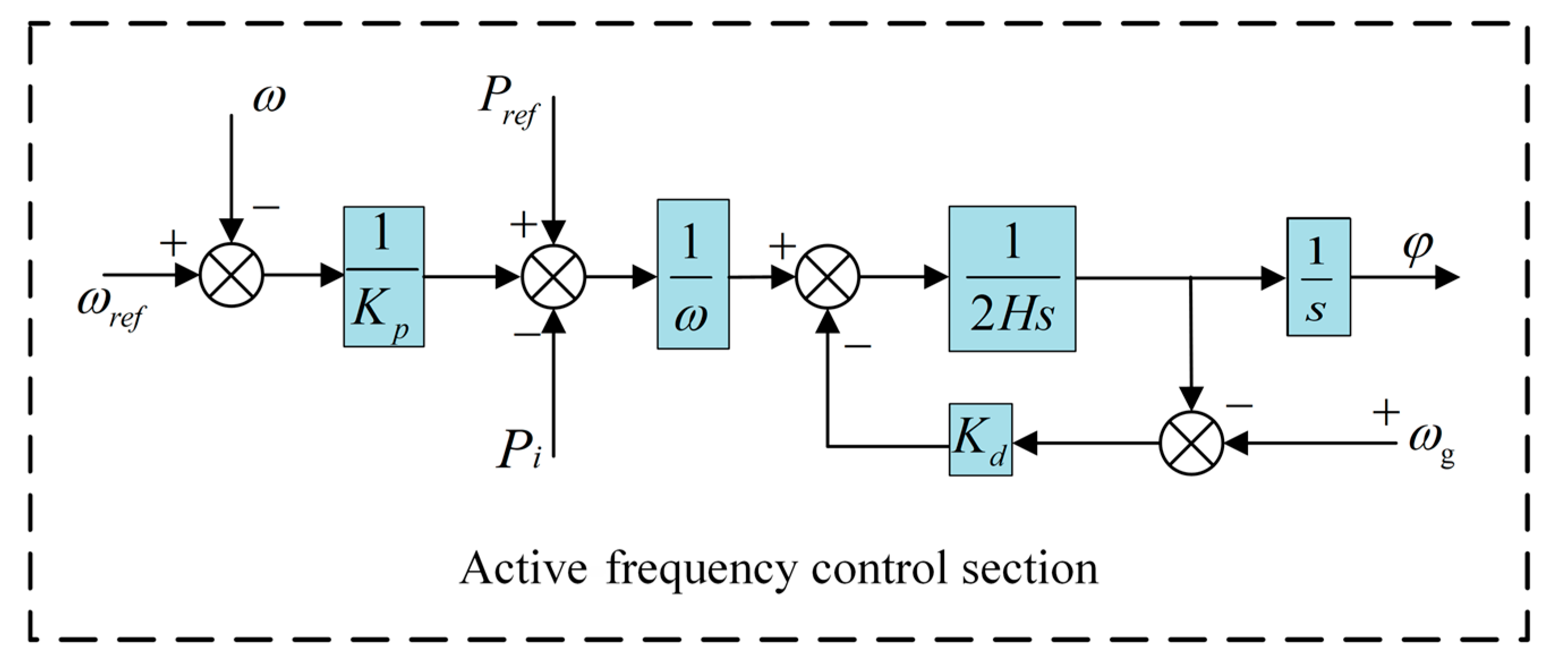
3.2.2. Virtual Synchronous Generator Control

The virtual synchronous generator (VSG) control strategy is built upon conventional droop control principles, while incorporating the electromechanical characteristics of synchronous generators. By emulating the rotor motion equations through advanced control algorithms, the VSG effectively enhances system inertia and damping properties at power electronic interfaces, thereby addressing the inherent limitations of traditional grid-connected converters. This type of control allows the inverter to act more like a synchronous generator with larger inertia in the grid, thus improving the stability and dynamic response of the grid [20].
For the active frequency control part, the VSG control mimics the rotor behaviour of a synchronous generator, and establishes a link between the active power P and the frequency ω through the rotational dynamics of the synchronous machine rotor. The specific active frequency control equation is as follows:
2 H d ω d t = P s e t P i K d ω 0 ω r e f d φ d t = ω
In Equation (1), H is the virtual inertia; the damping coefficient is Kd; Pset is the active power setting value; Pi is electromagnetic power; ω is defined as the output angular frequency of the inverter side; ω0 is the angular frequency of the common bus; ωref is the angular frequency setting value; and φ denotes the phase angle. The block diagram illustrating the active frequency control is presented in Figure 4.
A droop control loop can be incorporated into the control architecture to emulate the primary frequency regulation capability characteristic of synchronous generators, as shown in Equation (2).
P s e t = P r e f + 1 K p ω r e f ω
In Equation (2), Pset is the active power setting value; Kp is the active sag coefficient; Pref is the active power reference value; ωref is the angular frequency setting value; and ω is the output angular frequency of the inverter side.
For the reactive voltage control part, in order to simulate the excitation regulation function of the synchronous generator, and to ensure that the reactive load can be distributed in proportion to the capacity when the storage units under VSG control are operated in parallel, a reactive voltage regulator is used for the control, which is controlled according to Equation (3).
K i d E d t = Q r e f + K q U 0 U r e f Q 0
In Equation (3) Qref is the reactive power setting value; Uref is the voltage setting value; Q0 is the inverter output reactive power; Ki is the integral coefficient; U0 is the inverter output voltage amplitude; and Kq is the reactive power sag coefficient. Figure 5 presents a block diagram illustrative of reactive voltage control methodologies.
In summary, the grid-constructing VSG control realises the inertial frequency regulation of the grid by introducing damping and active sag control loops [26]. Compared with the traditional grid-following type control, the voltage and frequency support capability, adaptability, and stability of the grid-constructing type VSG control are significantly improved. In this paper, the grid-type VSG-controlled energy storage unit is used as the black start power supply, while the grid-following PQ-controlled energy storage unit is used as the other power supply in the black start, so as to ensure that the voltage and frequency of the system remain stable.

3.2.3. SOC Equalisation Control for Energy Storage Units

In the process of charging and discharging the energy storage unit, the SOC is a pivotal indicator of the available capacity of the energy storage unit. The internal SOC is calculated as follows:
S O C x = S O C x 0 1 C i i b a t x d t
In Equation (4), SOCx is the residual capacity of the x-th energy storage unit; SOCx0 is the initial charge of the x-th energy storage unit; Ci is the current storage battery capacity; and ibatx is the output current of the x-th energy storage unit.
This paper presents an integral feedback-based adaptive SOC balancing control for energy storage systems. The proposed strategy monitors individual unit SOCs, computes the system average, and distributes power commands accordingly, demonstrating rapid response and stable performance, as formulated in Equation (5).
P r e f x = S O C x S O C A V K c + S T i
In Equation (5), SOCx is the residual capacity of the x-th energy storage unit; SOCAV is average value; Prefx is the power output command for the x-th energy storage unit; Kc is the gain coefficient; S is the integration coverage; and Ti is the integration time constant. The control block diagram is shown in Figure 6.

4. Coordinated Control Strategies Applicable to Black Starting of PV-Based Energy Storage Microgrids

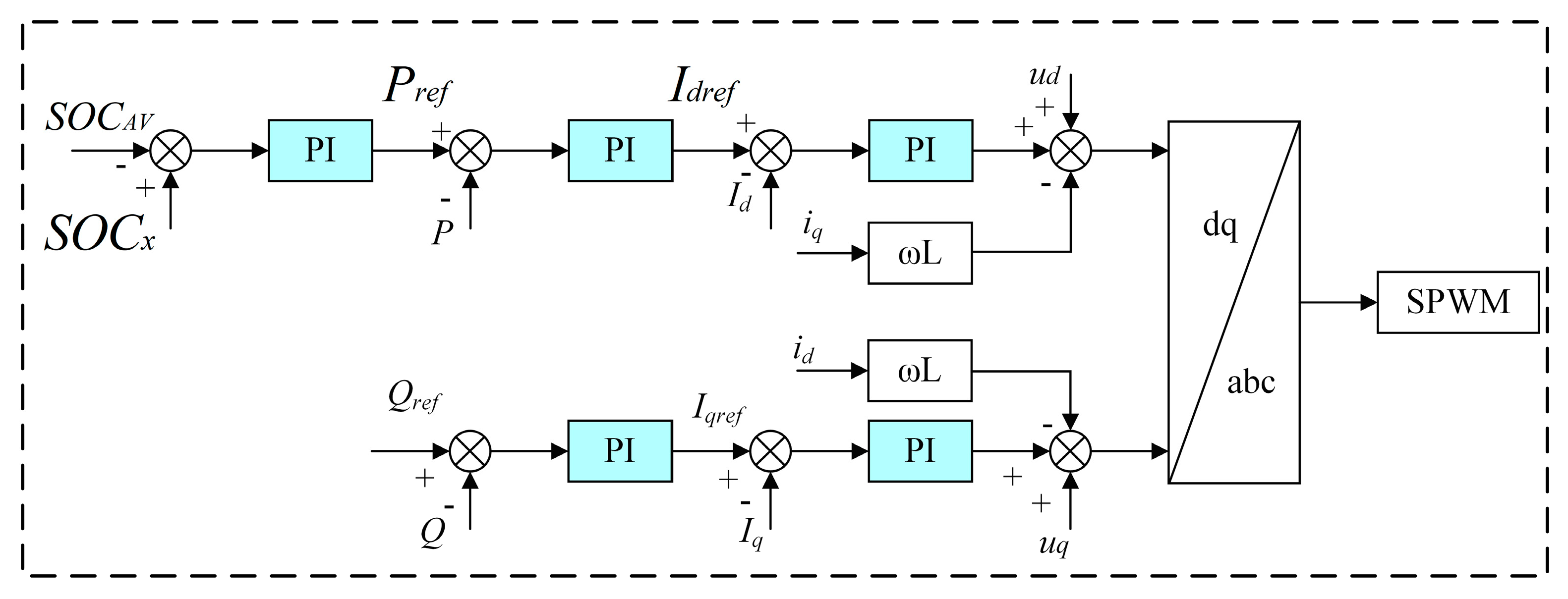
4.1. Black Start Coordinated Control Strategy Considering SOC of Energy Storage Units

In the black start process, the instability of distributed power output and the frequent casting and cutting of loads make the coordinated control of the PV-based energy storage microgrid more complicated. Considering that overcharging and overdischarging of energy storage units lead to black start failure, this paper proposes a coordinated black start control strategy for PV-based energy storage systems., as shown in Figure 7.
Under the control of the proposed recovery strategy, the SOC of the storage unit is balanced during the black start. At the same time, the PV system can be switched between the load tracking and MPPT modes, which avoids overstepping the SOC limit due to an insufficient residual charging capacity of the storage unit.

4.2. Coordinated Control of Black Start Active Power in PV-Based Energy Storage Microgrids

The expression for active power balance between the power source and the load after the PV-based energy storage microgrid is connected to the grid is given by the following:
P b a t i + P p v + P E m = P L o a d 1 + P L o a d 2 + P s
In Equation (6), Pbati is the energy storage system’s active power; Ppv is the photovoltaic system’s active power; PEm is the auxiliary engine’s active power; PLoad1 is the primary active load; PLoad2 is the secondary active load; and Ps is the internal active loss of the system.
As can be seen from Equation (5), when the PV output is greater than the load demand, the excess output of the PV will charge the energy storage system, and Pbati < 0; when the PV output is less than the system demand, the energy storage system is used to supplement the PV active output shortfall, and Pbati > 0. After the auxiliary machine is connected to the grid, if the electromagnetic torque is greater than 0, the auxiliary machine is in the electric state, PEm < 0; if the electromagnetic torque is less than 0, the auxiliary machine is in the power state, PEm > 0.

4.3. Coordinated Control of Black Start Reactive Power in PV-Based Energy Storage Microgrids

The expression for the reactive power balance between the power source and the load after the PV-based energy storage microgrid is connected to the grid is as follows:
Q b a t i + Q p v + Q E m = Q L o a d 1 + Q L o a d 2 + Q s
In Equation (7), Qbati is the energy storage system’s reactive power; Qpv is the photovoltaic system’s reactive power; QEm is the auxiliary engine’s reactive power; QLoad1 is the primary reactive load; QLoad2 is the secondary reactive load; and Qs is the internal reactive power loss of the system.
During a black start, the PV system usually provides only active power. The energy storage system provides transient reactive power support to the overall system by virtue of its fast response time, and maintains stable system operation.

5. Simulation Verification

5.1. Parameter Setting

In this study, a system simulation model (Figure 1) was implemented in PSCAD/EMTDC to assess the performance of the proposed black start recovery strategy. The simulation model contained distributed energy storage units, photovoltaic power plants, variable loads, and auxiliary machines. The initial SOC of each energy storage unit was set to different values to simulate the randomness of the black start event. According to the system configuration and technical parameters of the Qinghai Yushu Microgrid Project in China, as mentioned earlier, we set the total capacity of the energy storage system to 2.5 MW and the total installed PV capacity to 2 MW, and configured 0.5 MW of auxiliary backup capacity. We set the distribution network voltage level to 0.4 kV. The following tables show the parameters for each device. The parameters of the energy storage unit are shown in Table 1, the parameters of the photovoltaic system are shown in Table 2 and the parameters of the auxiliary machinery are shown in Table 3.

5.2. Simulation Analysis of PV-Based Energy Storage Microgrid Black Start

The black start scenario was set as follows: at the beginning of operation, the system was in a fully black state; at 0.5 s, the grid-constructing type VSG-controlled energy storage unit was activated; at 1.5 s, 1.6 MW + 0.3 Mvar were applied; at 4 s, the remaining two groups of grid-following-type controlled energy storage units were activated; at 12 s, the photovoltaic system was connected to the grid; at 16 s, 0.8 MW + 15 Mvar secondary loads were applied; at 18 s, an 0.5 MW auxiliary engine was applied to expand the black start recovery surface.

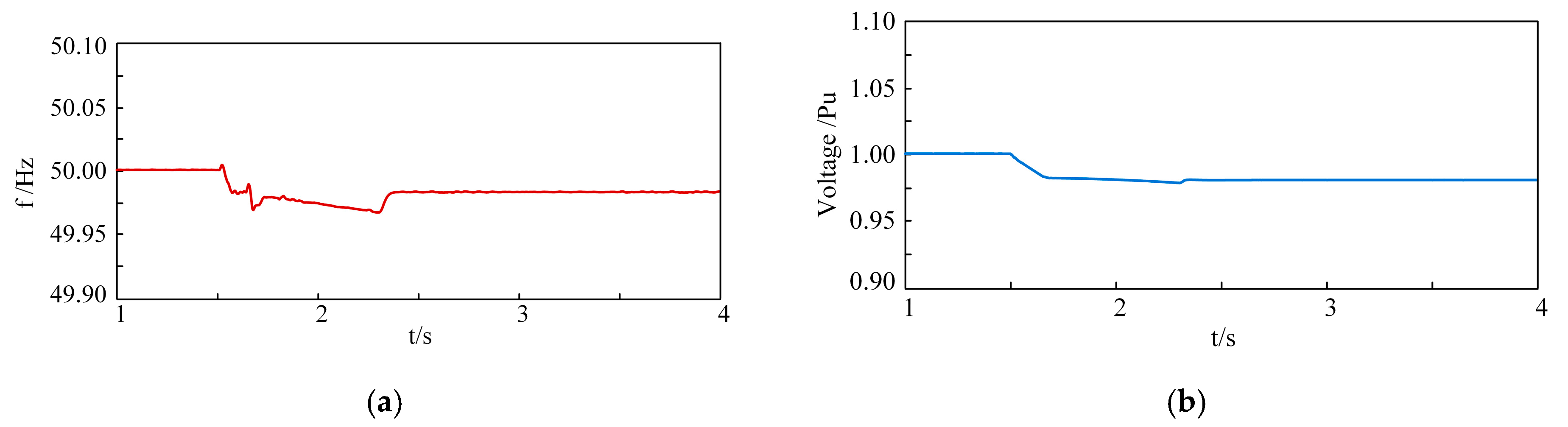
5.2.1. Simulation Analysis of Black Start in PV MPPT Mode

With the PV system set to always work in MPPT mode and intercept the black start at 1–4 s, the grid-constructing-type control energy storage unit established a stable system frequency and voltage from the beginning.
In Figure 8a,b, it can be seen that the grid-configured VSG-controlled energy storage unit can output a stable voltage and frequency, which provides the necessary conditions for a black start.
After the self-start of the grid-type energy storage unit establishes a stable frequency and voltage, the two groups of grid-following-type controlled energy storage units are activated at 4 s. Figure 9a–c show the output power of each distributed energy storage unit during the black start process.
At 12 s, when the PV system is connected to the grid, the PV system works in MPPT mode to maximise the power output. The PV power output during black start is shown in Figure 9d.
At 18 s, the time storage system jointly supplies power to the auxiliary engine, and the auxiliary engine is supported by the reactive power provided by the energy storage system during the start-up process; the auxiliary engine output power is shown in Figure 9e.
As can be seen from Figure 10 and Figure 11, the recovery is carried out in accordance with the proposed recovery strategy. The system frequency and voltage fluctuate to a certain extent when the load is applied, but they are all within a reasonable range. As can be seen in Figure 12, each energy storage unit carries out active load allocation according to its own SOC, and the SOC of each distributed energy storage unit gradually converges to the same level, which avoids overcharging or overdischarging of the energy storage unit.

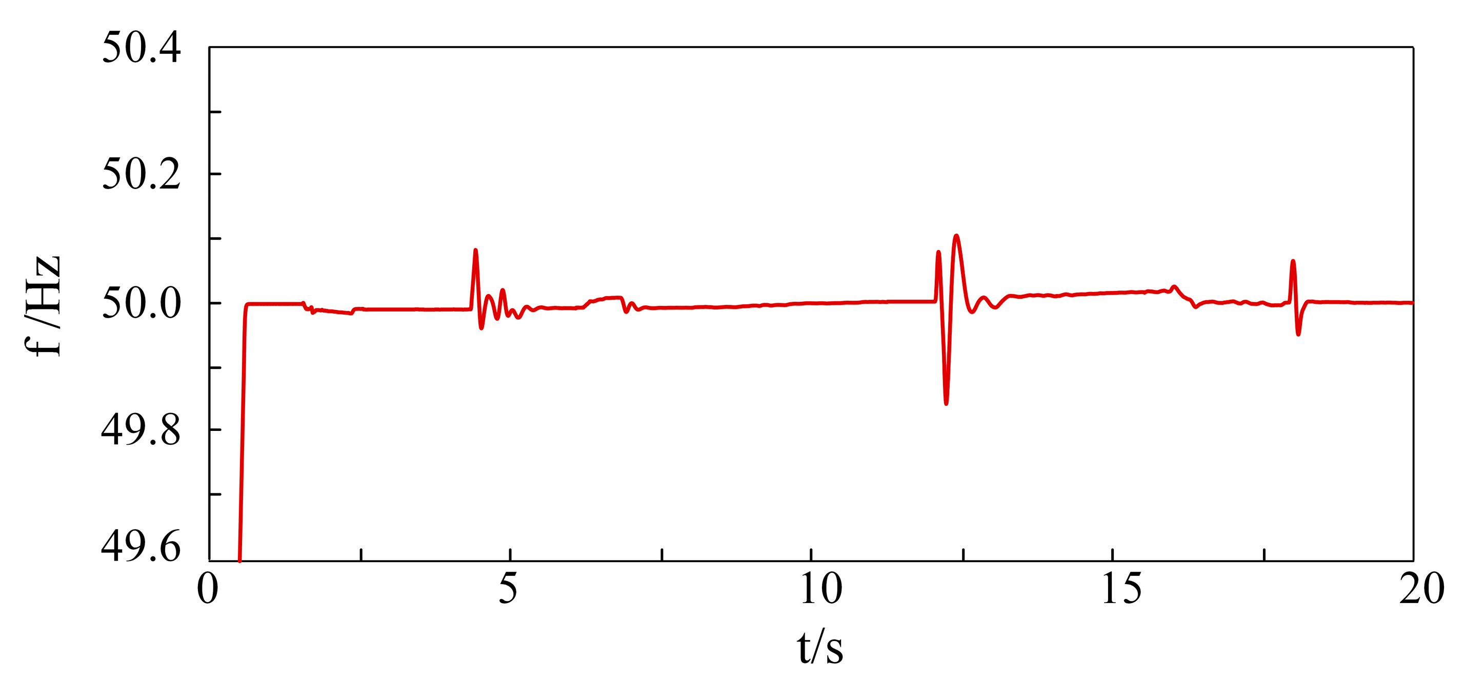
5.2.2. Simulation Analysis Under Coordinated Control of PV MPPT and Load Tracking

The PV system works in MPPT and load tracking coordinated control mode for a black start, and the simulation results are shown in Figure 13. Figure 13a–c show the waveforms of the output power of energy storage units during the black start process.
From Figure 13d,e, we can see that at 12 s, when the PV is connected to the grid, the PV works in load tracking mode. As the secondary load is put into operation at 16 s, the maximum output of the PV system is less than the load, and then it is switched to the maximum output of the MPPT mode, and the power deficit is borne by the energy storage system.
Figure 14 shows the variation in the SOC of the energy storage unit during the black start process. The results demonstrate effective SOC convergence across all storage units, ensuring compliance with operational limits.
The proposed MPPT–load tracking coordinated control significantly reduces the energy storage charging requirements compared to conventional MPPT operation, and there is no black start failure due to an insufficient residual capacity of the energy storage unit.

5.3. Discussion

This study proposes an SOC-aware black start strategy for PV storage microgrids, enabling autonomous grid restoration during complete system outages. The proposed method demonstrates superior performance over conventional approaches, as quantitatively compared in Table 4.
Although the simulation results show that this strategy is promising, there are still several research directions that need to be further strengthened.
  • This study has mainly considered PV systems and energy storage systems. Future work could involve wind power systems in black starting. As the number of distributed generation systems increases, the coordinated control and stability of the systems will become more complex. Future research could focus on distributed generation system control algorithms and hierarchical control structures to ensure system stability.
  • Although the proposed adaptive equalisation control of the SOC for energy storage achieves real-time equalisation of the SOC in simulation, the real-time optimisation of PID control parameters in dynamic environments is still a challenge.
  • Future research could prioritise the simulation of black starting of PV-based energy storage microgrids, considering energy storage SOCs, on hardware platforms, in order to assess these microgrids’ real-world performance.

6. Conclusions

In summary, we propose a PV-based energy storage microgrid black start recovery strategy to address the problem of failure due to SOC imbalance among distributed energy storage units in the black start process of PV-based energy storage microgrids, and we draw the following conclusions:
  • To address frequency and voltage instability during black starts, this study employs a grid-forming VSG-controlled energy storage system as the black start power source, achieving stable system frequency and voltage regulation throughout the restoration process.
  • The distributed energy storage unit designed in this paper adopts adaptive SOC non-deviation control, which can reasonably allocate loads according to its own state of charge, realising SOC equalisation among distributed energy storage units and avoiding black start failure due to storage SOC over-run in the black start process.
  • The proposed coordinated MPPT–load tracking control strategy maximises PV output, while enabling load-following operation, preventing black start failures due to insufficient storage capacity and minimising charge cycles.

Author Contributions

Methodology, X.L.; software, T.M. and Z.Z.; validation, X.L., Y.X. and K.W.; formal analysis, D.Z.; investigation, T.M.; resources, X.L.; data curation, Z.Z.; writing—original draft preparation, X.L.; writing—review and editing, X.L.; visualisation, D.Z.; supervision, Z.Z.; project administration, K.W.; funding acquisition, Y.X. All authors have read and agreed to the published version of the manuscript.

Funding

This research was funded by the Science and Technology Project of the State Grid Corporation of China, grant number kj2024-025.

Data Availability Statement

The original contributions presented in the study are included in the article, further inguiries can be directed to the corresponding author.

Acknowledgments

The authors gratefully acknowledge the anonymous reviewers for their valuable feedback and expert recommendations.

Conflicts of Interest

Authors Xiaoyu Li, Tianxiang Ma, Zhiyuan Zhang and Da Zhang was employed by the company Electric Power Research Institute of Hebei Electric Power Co., LTD. The remaining authors declare that the research was conducted in the absence of any commercial or financial relationships that could be construed as a potential conflict of interest. The authors declare that this study received funding from Science and Technology Project of State Grid Corporation of China. The funder was not involved in the study design, collection, analysis, interpretation of data, the writing of this article or the decision to submit it for publication.

References

  1. Zhao, H.Y.; Lin, Z.; Ding, Y.; Liu, Y.; Sun, L.; Yan, Y. A Model Predictive Control Based Generator Start-Up Optimization Strategy for Restoration with Microgrids as Black-Start Resources. IEEE Trans. Power Syst. 2018, 33, 7189–7203. [Google Scholar] [CrossRef]
  2. Qiu, F.; Zhang, Y.; Yao, R.; Du, P. Power System Restoration with Renewable Participation. IEEE Trans. Sustain. Energy 2023, 14, 1112–1121. [Google Scholar] [CrossRef]
  3. Wang, X.B.; Ge, J.; Han, L.S. Thinking and practice of grid-based energy storage to support the construction of new power systems. Power Syst. Prot. Control 2023, 51, 172–179. [Google Scholar]
  4. Dang, H.P.; Villegas Pico, H.N. Blackstart and fault ride-through capability of DFIG-based wind turbines. IEEE Trans. Smart Grid 2023, 14, 2060–2074. [Google Scholar] [CrossRef]
  5. Qiu, F.; Wang, J.; Chen, C.; Tong, J. Optimal Black Start Resource Allocation. IEEE Trans. Power Syst. 2016, 31, 2493–2494. [Google Scholar] [CrossRef]
  6. Sun, W.; Liu, C.C.; Zhang, L. Optimal Generator Start-Up Strategy for Bulk Power System Restoration. IEEE Trans. Power Syst. 2011, 26, 1357–1366. [Google Scholar] [CrossRef]
  7. Pan, Z.; Zhang, Y. Aflexible black-start network partitioning strategy considering sub system recovery timebalance. Int. Trans. Electr. Energy Syst. 2015, 25, 1644–1656. [Google Scholar] [CrossRef]
  8. Zhou, X.; Chen, W.J.; Dai, J.F. Considering the balanced distribution of energy storage SOC, the black-start coordinated control strategy of optical storage microgrid. J. Shanghai Jiaotong Univ. 2023, 395, 1–22. [Google Scholar]
  9. Patsakis, G.; Rajan, D.; Aravena, I.; Rios, J.; Oren, S. Optimal Black Start Allocation for Power System Restoration. IEEE Trans. Power Syst. 2018, 33, 6766–6776. [Google Scholar] [CrossRef]
  10. Liu, Y.P.; Hou, Y.X.; Liang, H.P. A Coordinated Control Strategy for Photovoltaic and Energy Storage Hybrid Power Generation System Suitable for Black Start. Power Syst. Technol. 2017, 41, 2979–2986. [Google Scholar]
  11. Wang, D.X. Research on Frequency Support Method and Black Start Strategy of Grid-Based PMSG Wind Power System; North China Electric Power University: Beijing, China, 2023. [Google Scholar]
  12. Zhan, C.J.; Wu, H.; Wang, X.F. A review of the stability of the reticulated converter. Proc. CSEE 2023, 43, 2339–2359. [Google Scholar]
  13. Wang, X.F.; Blaabjerg, F. Harmonic stability in power electronic-based power systems: Concept, modeling, and analysis. IEEE Trans. Smart Grid 2019, 10, 2858–2870. [Google Scholar] [CrossRef]
  14. Wang, X.F.; Taul, M.G.; Wu, H. Grid-synchronization stability of converter-based resources: An overview. IEEE Open J. Ind. Appl. 2020, 1, 115–134. [Google Scholar] [CrossRef]
  15. Zhou, J.Z.; Ding, H.; Fan, S.T. Impact of short-circuit ratio and phase-locked-loop parameters on the small-signal behavior of a VSC-HVDC converter. IEEE Trans. Power Deliv. 2014, 29, 2287–2296. [Google Scholar] [CrossRef]
  16. Li, D.; Zhu, Q.; Lin, S.; Bian, X.Y. A Self-Adaptive Inertia and Damping Combination Control of VSG to Support Frequency Stability. IEEE Trans. Energy Convers. 2017, 32, 397–398. [Google Scholar] [CrossRef]
  17. Chen, S.; Sun, Y.; Hou, X.; Han, H.; Fu, S.; Su, M. Quantitative Parameters Design of VSG Oriented to Transient Synchronization Stability. IEEE Trans. Power Syst. 2023, 38, 4978–4981. [Google Scholar] [CrossRef]
  18. Shi, R.L.; Zhang, X.; Liu, F. Research on the black start scheme of isolated microgrid based on virtual synchronous generator. Acta Energiae Solaris Sin. 2017, 38, 2857–2864. [Google Scholar]
  19. Huang, Q.Q.; Wang, W.; Deng, X.J. Research on the control strategy of grid-based photovoltaic self-synchronous voltage source. Power Electron. Technol. 2023, 57, 87–90. [Google Scholar]
  20. Shahparasti, M.M.; Laaksonen, H.; Kauhaniemi, K.; Lauttamus, P.; Strandberg, S.; Strandberg, J. Inrush Current Management During Medium Voltage Microgrid Black Start With Battery Energy Storage System. IEEE Access 2022, 10, 42287–42296. [Google Scholar] [CrossRef]
  21. Tobías, A.; Cárdenas, V.; Garcia-Beltran, C.D.; Miranda, H.; Álvarez-Salas, R. Optimal Power Sharing and Black Start Procedure in Photovoltaic Energy-Based Microgrids. IEEE Access 2023, 11, 74614–74626. [Google Scholar] [CrossRef]
  22. Zhao, Y.X.; Sun, L.; Lin, Z.Z. Microgrid as a black-start power source power grid reconstruction and optimization strategy. Autom. Electr. Syst. 2018, 42, 9–17+147. [Google Scholar]
  23. Zhang, Y.M.; Wu, J.Y.; Jiang, Q. Black start technology and coordinated recovery strategy of the receiver power grid based on the combined wind-storage system. Adv. Eng. Sci. 2023, 55, 72–83. [Google Scholar]
  24. Xie, N.; Yang, P.H.; He, P. Research on energy storage control strategy in the whole process of wind-solar storage microgrid-thermal power unit black start. Proc. CSU-EPSA 2023, 35, 75–82+93. [Google Scholar]
  25. Xiong, C.; Zhang, X.H.; Cao, W. Study on the limitation of VSG inertia under symmetrical fault of power grid and its combined effect with condenser. Power Energy 2020, 41, 9–12. [Google Scholar]
  26. Li, J.H.; You, H.F.; Qi, J. Stratified optimization strategy used for restoration with photovoltaic-battery energy storage systems as black-start resources. IEEE Access 2019, 7, 127339–127352. [Google Scholar] [CrossRef]
Figure 1. Topology of PV and energy storage hybrid power generation system.
Electronics 14 01696 g001
Figure 2. Control structure of photovoltaic system. Realistic experimental validation is essential to confirm its feasibility.
Electronics 14 01696 g002
Figure 3. Constant power control block diagram.
Electronics 14 01696 g003
Figure 4. Active frequency control block diagram.
Electronics 14 01696 g004
Figure 5. Reactive voltage control block diagram.
Electronics 14 01696 g005
Figure 6. Adaptive SOC equalisation control block diagram.
Electronics 14 01696 g006
Figure 7. Flow chart of coordinated control of PV-based energy storage system during black start.
Electronics 14 01696 g007
Figure 8. Black start power auto-start simulation results. (a) System frequency. (b) System voltage.
Electronics 14 01696 g008
Figure 9. Simulation waveforms of black start under conventional photovoltaic MPPT mode. (a) Storage unit 1 output power. (b) Storage unit 2 output power. (c) Storage unit 3 output power. (d) Photovoltaic system output power. (e) Auxiliary power output. (f) Auxiliary torque.
Electronics 14 01696 g009
Figure 10. System frequency under PV MPPT mode black start process.
Electronics 14 01696 g010
Figure 11. System voltage under PV MPPT mode black start process.
Electronics 14 01696 g011
Figure 12. SOC changes of energy storage units under PV MPPT mode.
Electronics 14 01696 g012
Figure 13. Simulation waveforms of black start under combined control of photovoltaic MPPT mode and load tracking. (a) Storage unit 1 output power. (b) Storage unit 2 output power. (c) Storage unit 3 output power. (d) Photovoltaic system output power. (e) Photovoltaic operating mode switching signal. (f) Auxiliary power.
Electronics 14 01696 g013
Figure 14. The change in the energy storage SOC under the combination of the PV MPPT mode and load tracking.
Electronics 14 01696 g014
Table 1. Storage unit parameters.
Storage Unit ParametersValues
Number of energy storage units3
Rated voltage690 V
Power rating1 MW/0.5 MW/1 MW
Initial SOC70%/80%/60%
SOC protection cap80%
SOC protection lower limit20%
Table 2. Photovoltaic system parameters.
Photovoltaic System ParametersValues
Number of photovoltaic units10
Rated voltage690 V
Power rating0.2 MW
Maximum power point voltage1.5 KV
Table 3. Factory auxiliary machine parameters.
Factory Auxiliary Machine ParametersValues
Power rating0.5 MW
Motor angular frequency314.1592 rads−1
leakage2.07 H
Stator winding end inductance0.0052 H
Rotor winding end inductance0.41 H
Rated voltage6 KV
Table 4. A comparison of traditional black start methods with the black start method of this study.
FeatureTraditional MethodsMethodology Proposed in This Study
Dynamic responseUsualFast
SOC managementVulnerable to over-runsSOC adaptive equalisation
Disturbance resistanceLimited impact resistanceHigh impact resistance
EconomicsHigh costLow cost
Disclaimer/Publisher’s Note: The statements, opinions and data contained in all publications are solely those of the individual author(s) and contributor(s) and not of MDPI and/or the editor(s). MDPI and/or the editor(s) disclaim responsibility for any injury to people or property resulting from any ideas, methods, instructions or products referred to in the content.

