1. Introduction
Rising ambient temperatures make air conditioners a necessity for maintaining comfort and protecting human health. However, the significant energy consumption of air conditioners is a pressing issue that requires attention. Compared with ordinary air conditioners, variable frequency air conditioners (VFACs) have been widely used in household appliances due to their energy-saving qualities. VFACs are capable of reducing annual energy consumption by 30~40% [
1]. This is because the electronic control module of a VFAC can adjust the compressor frequency according to transient cooling capacity requirements. The electronic control module integrates multiple high-power chips, such as the Intelligent Power Module (IPM), Insulated Gate Bipolar Transistor (IGBT), Fast Recovery Diode (FRD), and Rectifier Bridge. Extremely high ambient temperatures and limited space impede the heat dissipation of electronic control modules, resulting in a substantial increase in the temperature of electronic chips [
2]. In turn, the reliability and working performance of the VFACs will be largely compromised [
3]. Once the temperature exceeds the limit, VFACs must operate at a reduced frequency to ensure the reliability of their electronic control module, making it difficult to meet significant cooling capacity requirements in extremely high ambient temperatures [
4]. Thus, to guarantee the reliability and working performance of electronic control modules under such conditions, efficient and advanced thermal management designs must be developed [
5].
The existing cooling methods for electronic control modules include air-cooled heat sinks, liquid cooling, and heat pipes. For air-cooled heat sinks, Mohammad proposed a generalized optimization strategy to design optimized air-cooled parallel plate-finned heat sinks (PPFHSs) for practical applications [
6]. Lakshmanan introduced a heat sink with rectangular fins featuring a stepped profile, which improved the thermal performance from the baseline by 27% and achieved an average temperature reduction of 6 °C in a residential split variable frequency air conditioner [
7]. Mohammad proposed pin-fins with three different patterns to improve the cooling of the heat sink, including cross-pin-fins (CPFs), parallel-pin-fins (PPFs), and double-cross-pin-fins (DCPFs) [
8]. For liquid cooling, Feng Han proposed an integrated design for a liquid-cooled heat sink for a 30 kw motor inverter and optimized its geometrical configuration [
9]. Faizan Ejaz developed a two-phase immersion cooling system using HFE-7100 for cooling vertically mounted chips on a printed circuit board [
10]. X.L. Wu presented a two-phase microchannel heat sink using R245fa for cooling IGBT modules, investigating its flow boiling heat transfer performance and flow regimes [
11]. For heat pipes, Xia et al. proposed a novel thermal management solution based on the heat pipe heat sink (HPHS) that can cool an enclosed electronic control module [
12]. Zhao et al. introduced a novel heat sink for Insulated Gate Bipolar Transistor (IGBT) modules utilizing flat heat pipe arrays [
13]. Yue Ren developed a radiation-enhanced heat pipe radiator by integrating a conventional heat pipe radiator with a coating of silica microspheres and graphene composites to cool high-power IGBT modules, determining that the junction temperature of the IGBT can be reduced by 6.8 °C at 1500 W under forced convection [
14].
However, these traditional cooling methods also have notable drawbacks. Air-cooled heat sinks struggle to effectively cool the enclosed electronic control module in extremely high ambient temperatures and limited space. Liquid cooling systems require additional tubes and fail to achieve accurate thermal control. The structure of heat pipe cooling systems is typically complex, especially when constrained by the limited space available for electronic control modules, making large-scale production challenging.
Effective thermal management of the electronic control module is crucial for ensuring the reliability of VFACs and represents a key bottleneck restricting their full working performance [
15]. As an active cooling method, thermoelectric coolers (TECs) based on the Peltier effect can actively convert electrical energy into a temperature difference. TECs have several advantages, including excellent performance in handling high heat flux, no working fluid, a simple structural design, a fast thermal response, and high reliability [
16]. Additionally, the manufacturing process of TECs is sufficiently suitable for large-scale industrial production. Thus, TECs offer promising prospects for application in the thermal management of the electronic control modules of VFACs operating in extremely high ambient temperatures. Jiang Wang investigated the potential of TECs to cool core power devices in the control circuits of air conditioners, achieving an average temperature reduction of 47 K in power devices [
17]. Manoj Sasidharan highlighted the high potential of TECs to replace traditional air conditioner cooling methods, noting that efficient cooling performance and energy consumption remain key factors restricting large- and medium-scale commercial applications [
18]. Shuang Li proposed the direct integration of chips into TECs to actively cool high-power LEDs, resulting in a 51% reduction in working temperature [
19].
In this study, we employed TEC1-12706, a widely used commercial TEC, to cool an electronic control module. By adjusting the current of the TEC, we could precisely control the temperature of high-power chips, thereby ensuring the efficient working performance of the VFAC. Firstly, we designed four cooling schemes and established simulation models using Ansys Icepak. Then, we compared the temperatures of chips across different schemes. Finally, we analyzed the effects of electrical current, the number of TECs, and the heat sink’s specifications on the thermal performance of the cooling system.
2. Simulation Method
2.1. Simulation Model
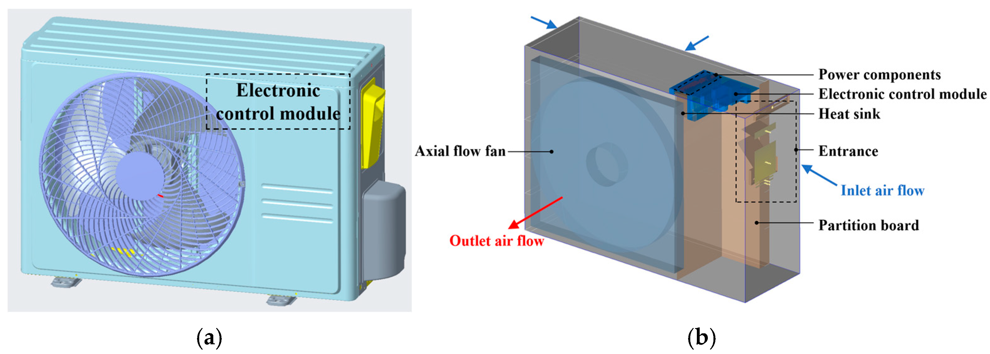
In this study, the simulation model of the outdoor unit was created based on the actual unit. The outdoor unit comprises a condenser, axial flow fan, electronic control module, heat sink, and compressor, as shown in
Figure 1a.
The electronic control module includes four main power components: the IPM, IGBT, FRD, and Rectifier Bridge, as shown in
Figure 1b. Heat dissipation is achieved by attaching a heat sink to these power components. To minimize the thermal contact resistance between the heat sink and the power components, silicon thermal grease is applied, as shown in
Figure 1c.
The heat sink utilizes parallel plate fins. Initially, the heat generated by the power components is transferred to the heat sink via conduction and is subsequently removed by airflow through convection. Enhancing both heat conduction and convection throughout this process can significantly improve the thermal performance of the cooling system for the electronic control module. TECs can actively transfer heat from the chips to the heat sink base, thereby facilitating efficient heat dissipation at the expense of electrical energy. Meanwhile, the heat convection performance is influenced by the specifications of the heat sink. In this study, the optimization effects of TECs on the cooling system in conjunction with various heat sink specifications are investigated.
Numerical simulations were conducted using the commercial software Ansys Icepak 2022 R1. The flow and thermal fields were simultaneously determined in an extreme ambient temperature of 55 °C. The models and methods used are briefly described below.
Figure 2a shows the outdoor unit’s assembly and the location of the electronic control module. To simplify the simulation model, the condenser, compressor, and associated tubes were ignored. The final cabinet and electronic control module used in Icepak are shown in
Figure 2b. The air was exhausted by an axial flow fan to create a negative pressure environment that drew cool air from the compressor chamber across the fins, facilitating convective heat dissipation. The main power components include the IPM, IGBT, FRD, and Rectifier Bridge. For simplicity, the silicon thermal grease between the heat sink and power components was omitted in the simulation.
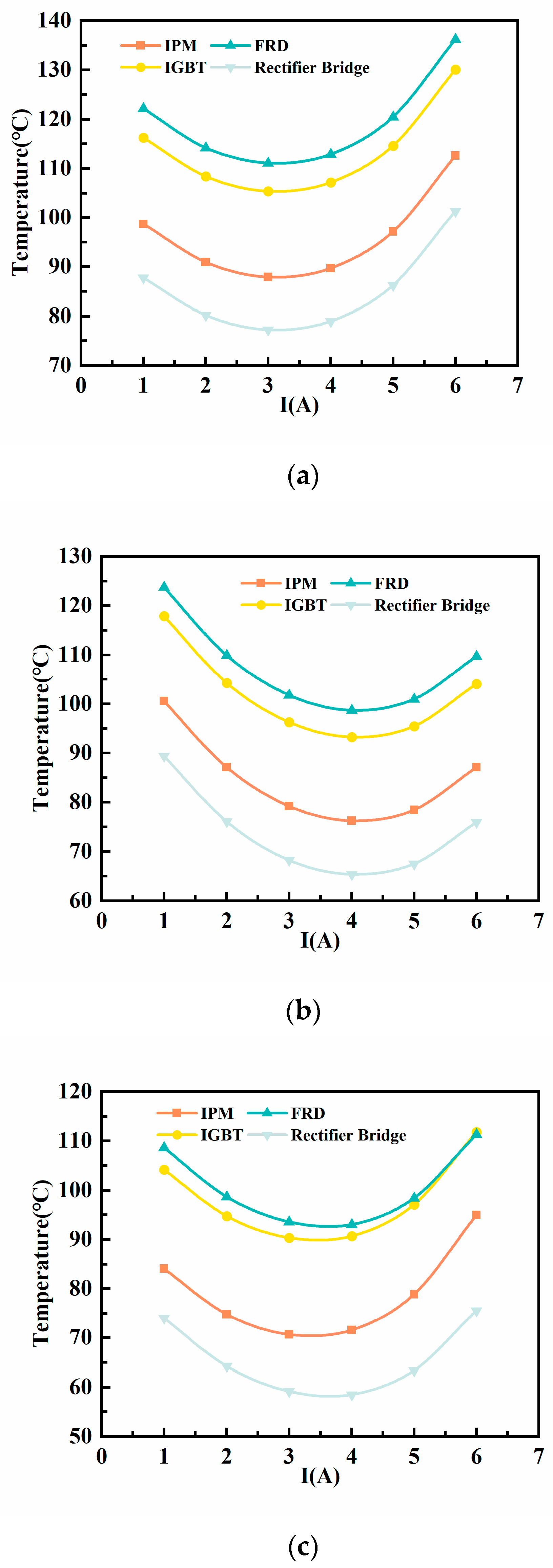
In this study, we investigated the heat dissipation optimization effects of varying TECs and different heat sink specifications.
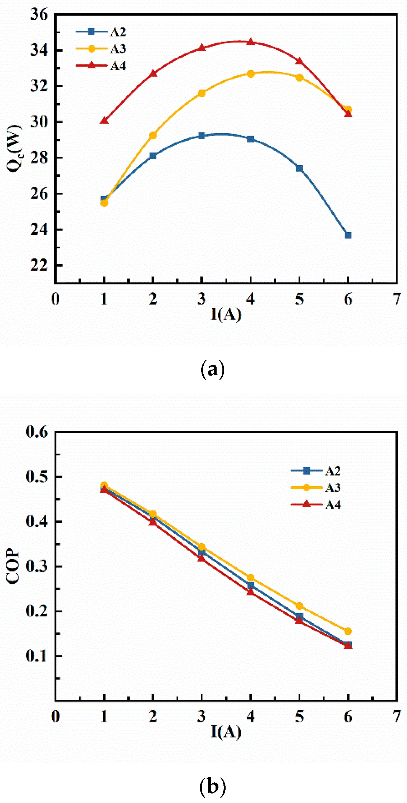
Figure 3 presents the schematic diagrams of the four cooling schemes. Scheme A1 employed parallel fins. Scheme A2 incorporated a single TEC between a soaking plate and parallel fins. Scheme A3 used a single TEC between a soaking plate and oblique fins. Scheme A4 featured two TECs between a soaking plate and parallel fins.
The heat sink and soaking plate are made of aluminum alloy. The soaking plate is used to evenly distribute the heat generated by the heating elements. The heating elements were built using packages created in Icepak. The printed circuit board (PCB) is simplified as a block, with the material set to FR-4. The air deflector is defined as an adiabatic thin surface.
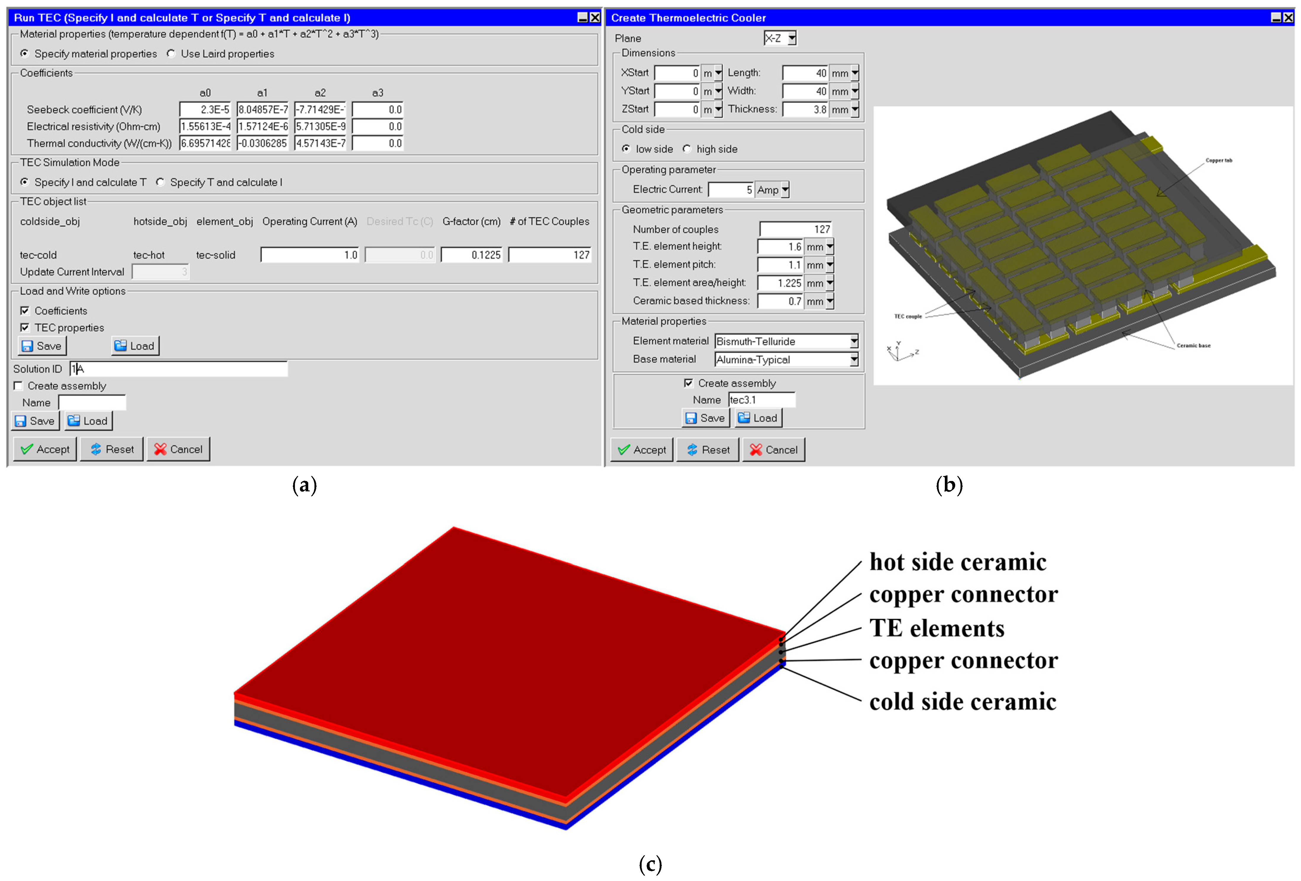
TEC1-12706 was built using the TEC macros in Icepak, as shown in
Figure 4. The material properties of Bismuth Telluride (Bi
2Te
3) thermoelectric materials are temperature-dependent, as detailed in
Table 1. The geometric parameters of the TEC module are listed in
Table 2. Other material properties were obtained from the material library in Icepak.
The reliability of the TEC model was validated by comparing the numerical results with the experimental results. In the experiment, the hot side temperature of the TEC was maintained at 27 °C using a liquid-cooled plate, while the operating current was controlled by a power source. The cold side temperature was measured using thermocouples, and the experimental results represent steady-state values that were sustained for over ten minutes at the specified operating current. The experimental uncertainty was ±%. The comparison between the experimental and numerical results is shown in
Figure 5. The numerical model demonstrated a good degree of agreement with the experimental data, with an average relative error of 4.34% and a maximum relative error of 6.8%, indicating that the model is viable.
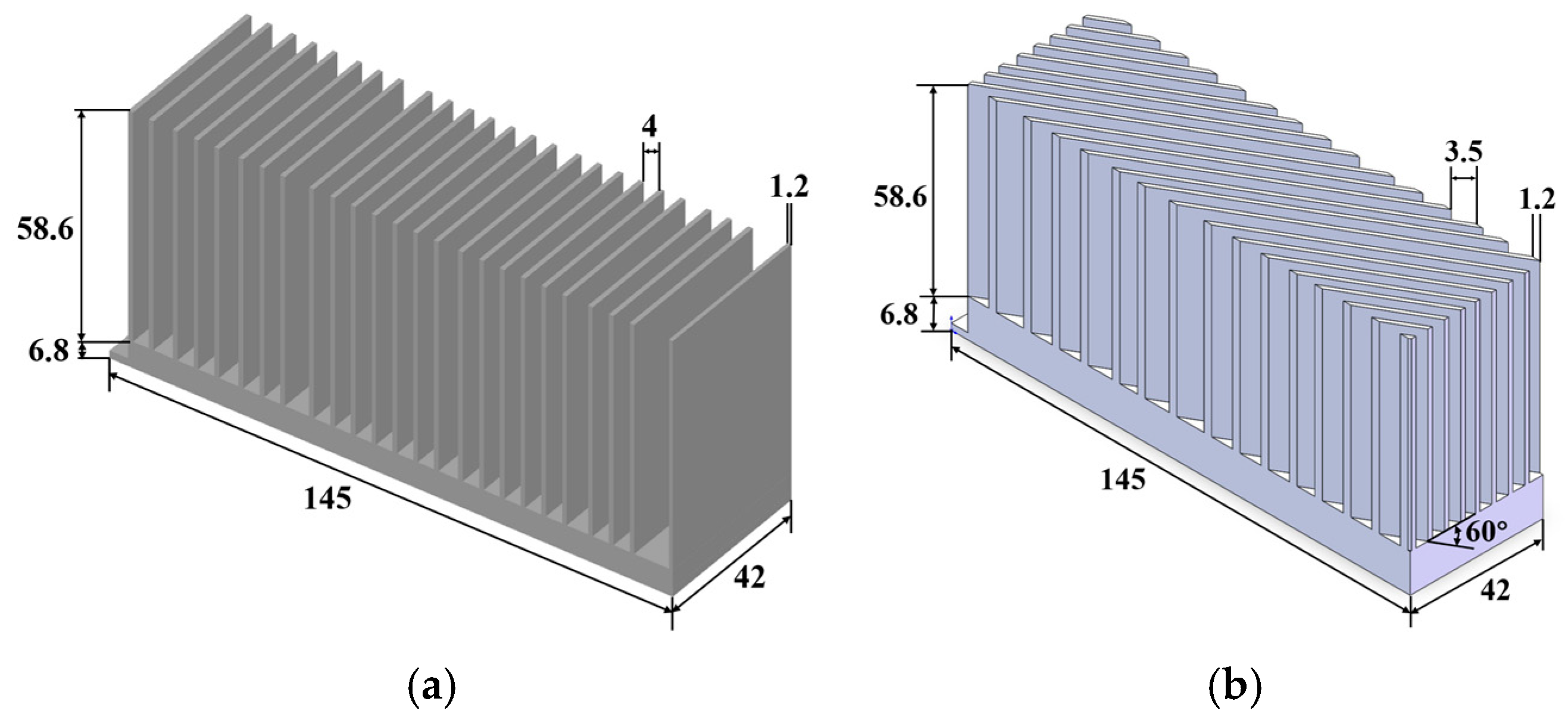
Figure 6 illustrates the two different specifications of parallel fins and oblique fins. Both fin types have a base area of 145 × 42 mm
2 and a thickness of 6.8 mm. However, the fin height is identical, reaching 58.6 mm in both designs. The primary difference is that the oblique fin is angled at 60 degrees between the fin side and the short side.
2.2. Numerical Solvers and Boundary Conditions
According to the approximate Reynolds and Peclet numbers provided by Icepak, the zero-equation turbulent model, coupled with the energy equation, continuity equation, and steady-state Navier–Stokes equation, is employed to calculate the temperature and flow fields, with radiation effects included.
To simulate heat dissipation in extreme conditions, the ambient temperature is set to 55 °C. The axial flow fan is modeled as a volumetric boundary condition with a fixed flow rate of 46.87 m3/min. The openings and grills of the air inlet are defined as pressure boundary conditions with ambient static pressure.
The IPM, IGBT, FRD, and Rectifier Bridge are considered constant heat sources. Their thermal powers, calculated using PLECS based on the datasheet parameters, are 12 W, 12 W, 7 W, and 3.5 W, respectively, for the IPM, IGBT, FRD, and Rectifier Bridge. The silicon thermal grease between the heat sink and power components is neglected for simplicity.
The operating current of the TEC varies from 1A to 6A to identify the optimal current that achieves the best heat dissipation performance.
2.3. Grid Independence Analysis and Model Validation
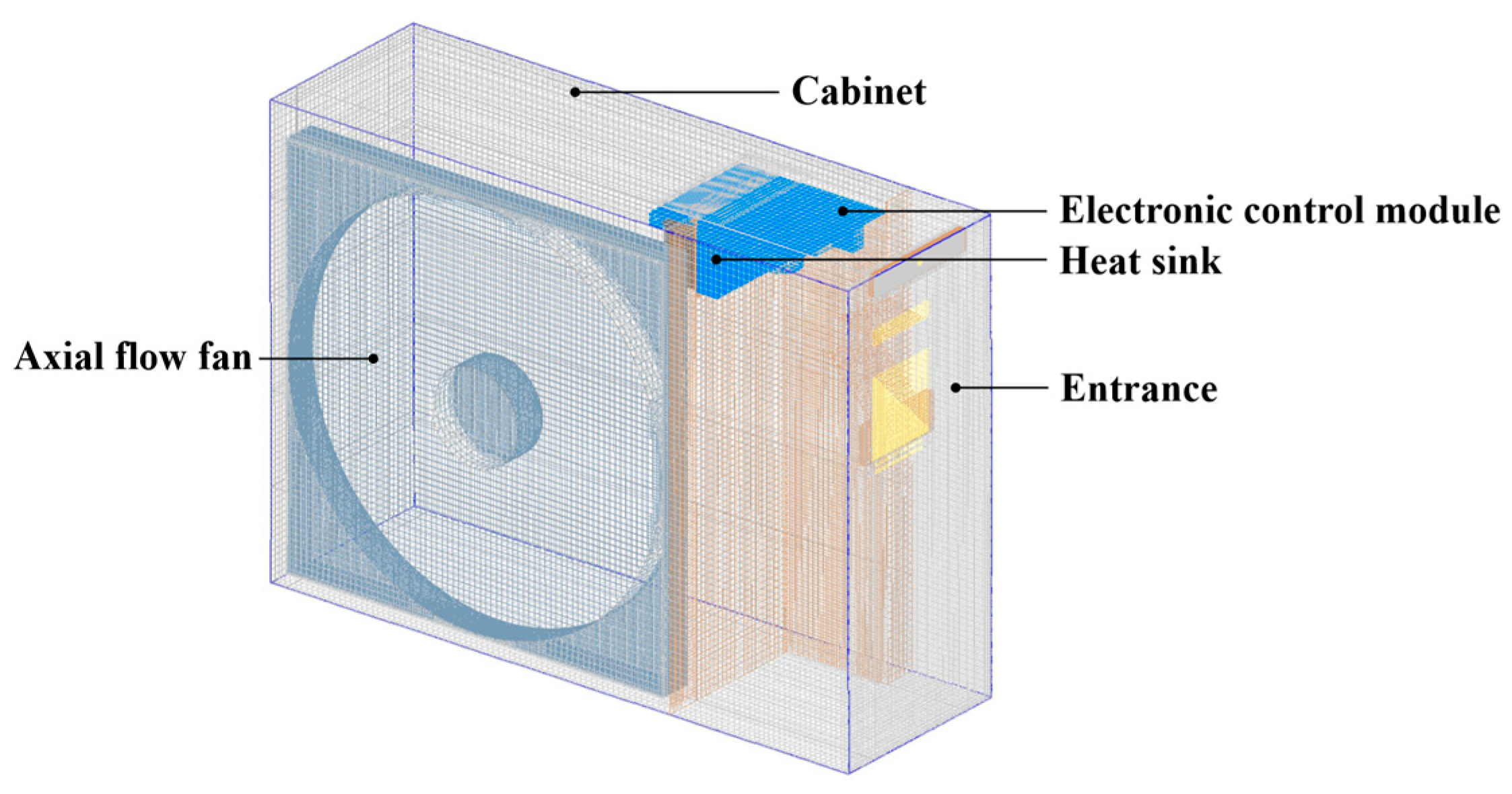
Taking Scheme A1 as an example, the entire model is divided into several assemblies to generate non-conformal grids conveniently in Icepak, as shown in
Figure 7. Hexa Unstructured grids are used for power components and heat sinks, while Mesher-HD grids are generated for the cabinet. The grids of the electronic control module and entrance are refined to improve simulation accuracy.
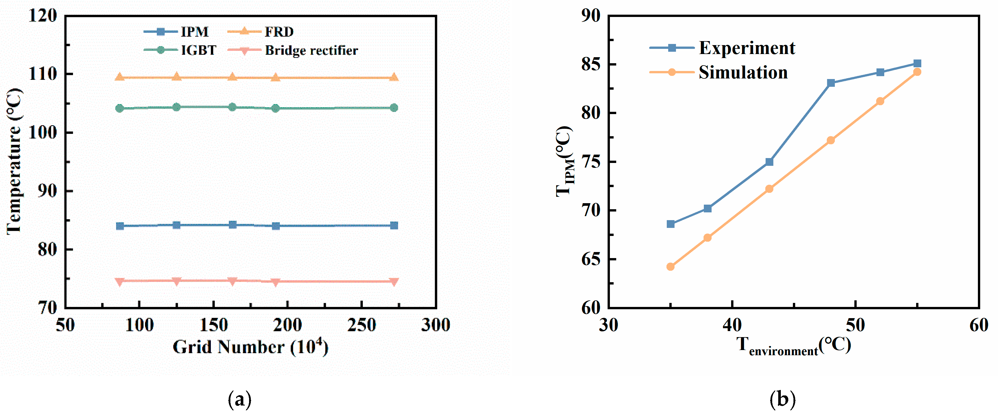
Grid independence was investigated by conducting simulations with five different grid numbers to choose a suitable meshing method. The average temperatures of the power components were used as monitoring parameters. As shown in
Figure 8a, with an increasing grid number, the average chip temperature varied by less than 1 °C. Considering both computational accuracy and efficiency, a grid number of 1,251,221 was considered suitable and was used for subsequent simulations.
The reliability of the simulation model was validated by comparing the numerical results and experimental results of the average temperature of IPM at different ambient temperatures. The experiments were conducted in an enthalpy difference laboratory to determine the specified and stable ambient temperatures. The compressor frequency was controlled by a computer. The temperature of the IPM was measured using thermocouples, and the experimental results represent the steady-state values maintained for over forty minutes at the specified ambient temperature and compressor frequency. The experimental uncertainty was ±2.5%. The comparison between the experimental and numerical results is shown in
Figure 8b. As the ambient temperature increases, the numerical results agree well with the experimental results. The average relative error was 4.35%, and the maximum relative error was 7.09%. These results confirm the validity of the numerical model for subsequent simulations.
4. Conclusions
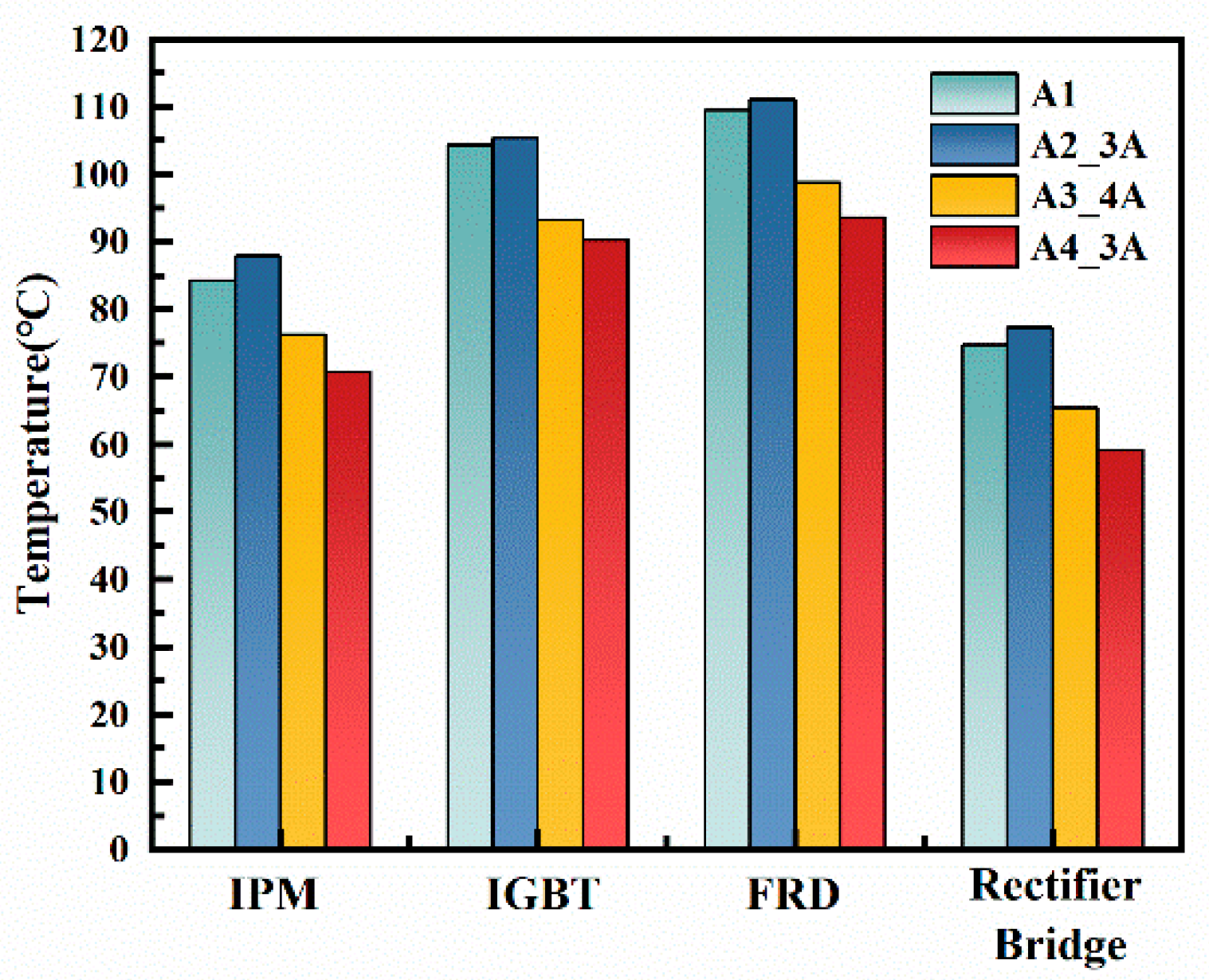
To guarantee the reliability and working performance of VFACs operating in extremely high ambient temperatures of 55 °C, we propose a feasible thermal management design based on thermoelectric coolers (TECs) that can cool the electronic control module. As discussed above, TECs have a significant impact on thermal performance. However, insufficient heat dissipation from the hot side of the TEC can lead to a deterioration in cooling performance due to the added Joule heat. Enhancing the heat dissipation capacity of the hot side or increasing the number of TECs can improve the cooling capacity. In Scheme A3, the average temperature decreases of the IPM, IGBT, FRD, and Rectifier Bridge were 7.97 °C, 11.08 °C, 10.76 °C, and 9.35 °C, respectively. In Scheme A4, these decreases were even more pronounced, with reductions of 13.58 °C, 14.03 °C, 15.88 °C, and 15.56 °C, respectively. Compared with other cooling methods, the temperature reductions achieved with TECs are highly noticeable. This enables VFACs to operate at their full potential in extremely high ambient temperatures. This study explores the application of TECs to cool the electronic control modules of VFACs in extremely high ambient temperatures. Our findings suggest that TECs can be effectively utilized on a large scale in the commercial VFAC field.


 and
and 


