Abstract
This paper proposes a frequency-modulated continuous-wave synthetic aperture radar (FMCW-SAR) imaging system for fast target detection. The system’s antenna array improves azimuthal resolution while maintaining low complexity using a 44-element equivalent virtual array and improves the data acquisition efficiency by employing the trigger and MCU control board. A series of improved algorithms are adopted to increase the speed of radar imaging and achieve fast detection. To solve the problem of large data volumes in traditional array antenna switching control methods, an array switching control algorithm is proposed based on the enhanced ordered statistical constant false alarm rate (EOS-CFAR). The data volume is reduced by dividing the array into several subarrays in advance. The echo signals acquired by the array switching control method are not continuous in the azimuthal direction, and data anomalies are handled by interpolating and compensating the received radar data to form compensated periodic data. The coherent background is subtracted from the padded signal using recursive averaging, resulting in high-resolution imaging while improving the data-processing speed. The TensorFlow-based Omega-K algorithm is employed for synthetic aperture radar (SAR) imaging, which customizes the optimization of TensorFlow for array radar signals. For the radar signal phase optimization, an improved Adam Optimizer optimizes the phase of the radar signal to maintain phase smoothing, thereby improving the clarity of the radar image. The Omega-K algorithm is optimized by TensorFlow and accelerated on the GPU to improve the efficiency of the large-scale fast Fourier transform (FFT) and Stolt interpolation operations, which improves the speed of radar imaging and enables fast detection.
1. Introduction
In recent years, there has been increasing interest in the development of more accurate and faster SAR imaging systems [1,2,3]. SAR systems can operate day and night and in a variety of weather conditions, unaffected by clouds, rain, and snow. This capability makes SAR highly valuable for disaster monitoring, military reconnaissance, and environmental surveillance. In the study of SAR, the integration of frequency-modulated continuous-wave (FMCW) technology [4,5] with SAR has become a prominent research focus [6,7,8,9]. SAR based on time division multiplexing (TDM) FMCW has the advantages of high resolution and low complexity [10,11]. Traditional FMCW radar systems use one or a few antennas to transmit and receive FMCW signals for target detection. However, the system has poor real-time performance, low spatial resolution, and difficulty in accurately distinguishing the spatial locations of multiple targets.
Array antenna radar can achieve a larger equivalent virtual antenna array by coherently receiving and processing multiple antenna elements [12]. This approach enables a wider scanning range and improved azimuth resolution. However, the traditional array antenna switching method loops in a specific order [13,14,15,16]. If the antenna combination is turned on when the target is not within its detection range or if the target signal cannot be effectively captured due to other factors, then the data generated by this antenna combination during these time periods are invalid. The antenna switching method generates a large volume of useless data, which causes data waste and increases the data-processing burden of the system. By improving the radar switching control method, the amount of useless data received can be reduced. Constant false alarm rate (CFAR) detection is a widely used adaptive algorithm in radar systems for detecting target echoes in noise, clutter, and interference. Common one-dimensional CFAR algorithms include the cell-averaging constant false alarm rate (CA-CFAR) and the ordered statistical constant false alarm rate (OS-CFAR) [17,18,19,20]. The CA-CFAR performs well in environments with uniformly distributed noise. However, the detection performance of the CA-CFAR is degraded when the target is surrounded by interference or clutter [21]. The OS-CFAR is an adaptive threshold algorithm widely employed in target detection. The algorithm identifies target signals in background noise and clutter by statistically sorting echo signals and adjusts the detection threshold to maintain a constant false alarm rate. The OS-CFAR algorithm can maintain a low false alarm rate and high target detection capability when there is dense clutter or changing signal strength by adjusting the target detection threshold [22]. Therefore, applying the OS-CFAR algorithm to the array antenna system can improve the array switching control strategy based on real-time target information and efficiently improve array switching control. However, when the background noise varies, local noise adaptation becomes a problem.
The array antenna system achieves real-time array switching control. However, when the antenna array detects multiple targets, not all array elements are active at the same time. Jumps or intervals in the array element switch-on sequence [23] result in switched-on array elements not being in sequence when the data are acquired, and data anomalies occur when conventional imaging algorithms are used. Therefore, it is necessary to supplement the acquired data. Due to space radiation, coupling, and the conduction surfaces of components, the high-power signal from the transmitter can leak into the receiver channel and seriously affect the reception operation. This leakage signal exhibits high energy, while the energy of target-reflected electromagnetic waves is low [24]. This leakage signal can obscure the target signal and hinder the acquisition of useful information. Therefore, it is necessary to treat such background noise [25].
Among various radar imaging methods, the Omega-K algorithm [26,27] avoids the dependence between distance time and azimuth frequency, and it has been widely used because of its ability to deal with complex targets. Compared to traditional SAR imaging approaches, the Omega-K algorithm adopted here avoids azimuth–range coupling limitations inherent in the range-Doppler (RD) algorithm [28] and reduces computational complexity relative to back-projection (BP) algorithms [29]. Although Doppler Beam Sharpening (DBS) enables real-time processing, it sacrifices resolution [30]. One of the main problems with the Omega-K algorithm is its computational complexity, which is mainly based on large-scale FFT and Stolt interpolation. Therefore, the problem of the computational burden of the system needs to be solved. In addition, based on array matrix signals, the Stolt interpolation and FFT operations in the Omega-K algorithm require custom kernel optimization [31,32,33,34]. Furthermore, the imaging quality can be improved by further enhancing the phase smoothing of the radar signal.
In this paper, we propose an array-radar-based FMCW SAR imaging system and fast detection method for targets. The system employs an improved data acquisition method while accelerating the imaging speed through a TensorFlow/GPU-based method, effectively speeding up target detection. The main contributions of our scheme are as follows:
- We adopt a low-complexity, low-cost S-band antenna array radar that consists of 44 equivalent virtual array antennas comprising 13 transmitting antennas and 8 receiving antennas to enable scanning over a larger range and improve the azimuthal resolution of the radar. The antenna array radar can achieve a larger equivalent virtual antenna array through the coherent reception and processing of multiple antenna elements. The radar system acquires trigger signals by employing the trigger, and the acquired radar data matrix is partitioned according to the trigger signal emitted by the trigger to obtain complete data from one array antenna scan. The system can control the antenna array switch via the MCU control board. The phase of the transmitted signal is phase-locked through a phase comparison and feedback mechanism, which improves the linearity of the signal.
- We propose a method for controlling antenna array switching based on the enhanced ordered statistical constant false alarm rate (EOS-CFAR). The array antenna system is combined with the EOS-CFAR to realize real-time array switching control. We apply complementary zero padding to the acquired data to address data anomalies. We propose a background subtraction method based on recursive averaging that reduces or eliminates background noise and improves the processing speed by processing the time-domain data directly.
- For the target detection method for radar imaging, we employ an improved Adam optimizer to improve the clarity of radar images and the accuracy of target detection by dynamically adjusting the phase of the radar signal and keeping it smooth. We employ the TensorFlow-optimized Omega-K algorithm for radar imaging based on array radar signals, which can process large data in parallel by optimizing the GPU, greatly improving the computation speed of FFT and Stolt interpolation. The feasibility of the method is verified by simulation, and fast target detection is achieved.
We organized the remainder of this paper as follows. In Section 2, we introduce the structure of the radar system. In Section 3, we describe the improved signal data collection methods in detail. Then, we describe our improved target imaging method in Section 4. In Section 5, we present experimental results to confirm the feasibility of our method. Finally, we conclude this paper in Section 6.
2. System Structure
The proposed FMCW SAR radar system mainly consists of a phase-locked loop (PLL), a voltage-controlled oscillator (VCO), a power divider, a coupler, a mixer, an MCU control board, RF switches, and an ADC acquisition module. Figure 1 shows the structure of the system. The system structure has low complexity, and its advantages include miniaturization, low power consumption, and low cost. In contrast to the traditional radar system, the system can control the antenna array switch via the MCU control board, and a pulse trigger is used to collect the antenna array switch signal to provide data labels for subsequent radar data preprocessing. The acquired radar data matrix is partitioned according to the trig signal to obtain the complete data from one array antenna scan. Unlike the traditional point-frequency PLL, the proposed specialized PLL offers a wide range of frequency modulation, supports frequency sweeps, and allows dynamic frequency adjustments based on requirements [35]. Meanwhile, phase noise is suppressed by optimizing the reference source and frequency divider. The PLL model number is ANALOG DEVICES EV-ADF4159EBxZ. The VCO, with a specialized phase-locked loop structure, generates a high-linearity continuous-wave signal, which is then amplified. The reflected signal is filtered and mixed with the local oscillator (LO) signal to generate the differential frequency signal. The differential frequency signal passes through a low-pass filter (LPF) to generate an IF signal, which is then collected by the ADC and uploaded to the PC for processing.
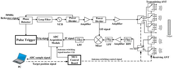
Figure 1.
The structure of the radar system.
Figure 2 shows the structure of the proposed array radar. The system designed in this study is an S-band antenna array radar consisting of 13 transmitting antennas and 8 receiving antennas [36]. Different combinations of antennas form 44 equivalent virtual array units, which are switched between different virtual arrays using RF switches to detect targets. Once acquired, the radar data can be divided into 44 columns consisting of different array elements. In antenna arrays, the transmitting and receiving antennas may form the virtual aperture [37]. Due to the relatively small size of the SAR, the target scene is within the main beam of each element [12]. Traditional antenna arrays with virtual array elements are switched by looping through the activation from 1 to 44 sequentially. However, the virtual array element activation of the antenna array in our system is dynamically localized sequentially. The formula for azimuthal resolution is as follows [38]:
where , N is the number of elements, d is the element spacing, and is the wavelength. The azimuth resolution is determined by the array aperture length L. The virtual aperture spacing of the designed antennas is . The azimuthal resolution of the structure is calculated as follows:
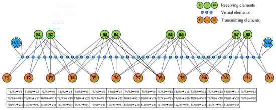
Figure 2.
An illustration of 13TX-8RX antenna arrays.
In contrast, the uniform antenna array with the same number of antennas has an angular resolution of 2.86°. In comparison, the azimuthal resolution of the proposed virtual array is 2.15 times higher than that of the ULA.
3. Improved Signal Data Collection and Processing Methods for Fast Radar Imaging
In this section, we propose array antenna switching control algorithms that can improve the efficiency of radar data acquisition. The problem of anomalous data in the acquired radar data is solved by our improved radar signal data-processing algorithm for filling in data. Finally, we improved the data quality while increasing the speed of data processing by directly performing coherent background subtraction based on the adaptive recursive method on time-domain radar data.
3.1. Improved Array Antenna Switching Control Algorithms
To accurately detect targets, an enhanced ordered statistical constant false alarm rate (EOS-CFAR) algorithm is proposed. The algorithm can effectively reduce invalid radar data by optimizing the control antenna array switching. The EOS-CFAR algorithm was developed based on the OS-CFAR algorithm, with the subarray configuration adjusted according to the expected target size, direction, and motion characteristics. Subarray division is performed to optimize the computational efficiency of the system. The EOS-CFAR algorithm is further enhanced with a target detection sliding-window method, in which the cell under test (CUT) is integrated with multiple array elements and dynamically adjusted according to the target size. The specific flowchart is shown in Figure 3.
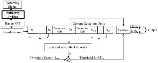
Figure 3.
EOS-CFAR schematic.
The EOS-CFAR algorithm is processed for different combinations of array elements. When the size of a target exceeds the resolution of a single virtual array element, the echo changes from a point-target model to an extended-target model, continuously spanning multiple array element combinations along the orientation dimension. This process allows the system to acquire detailed target distribution information, even in complex noise environments. The training unit x is a collection of neighboring data units selected to estimate the noise or clutter background during detection. This algorithm arranges all magnitude values of all training units in ascending order and then selects the k-th value.
The relationship between the threshold factor of the order statistic (OS) method and the predefined probability of a false alarm is outlined in Equation (2) [39]. This relationship demonstrates that the probability of false alarms is unaffected by clutter parameters. Furthermore, the detection probability of the OS method is presented in Equation (3) [39]:
where is the length of the reference window of the EOS-CFAR algorithm, and K is an ordered statistic. The appropriate selection of K is related to the merits of the detection results. In this multi-target scenario, a K value of approximately ensures a minimum false alarm rate [40]. is the signal-to-noise ratio (SNR).
In the EOS-CFAR algorithm, an antenna array that can detect the target with relevant antenna switching is marked as , and only the combinations of antenna arrays that can detect the target’s correlation are turned on for the subsequent target detection. The amplitude detection process is carried out for to derive the specific array element , represented by the highest value of the signal amplitude in .
where is considered the best element of the observation matrix among the current antenna switching signal markers , where the target echo signal is the strongest and the observation effect is the best. In the loop process, if shifts, the relevant antenna array combination is turned on or off. If no target is detected by during a loop, the current antenna array sliding-window combination is turned off. When the loop time reaches the antenna array scanning period T, the remaining antenna array combinations are turned on, the target situation is updated, and the loop array is entered again. The steps of this algorithm are comprehensively delineated in Algorithm 1.
Regarding the detailed steps of the algorithm in Algorithm 1, there are a few points that need to be clarified. The division of the antenna subarray needs to be based on the target size.
The following computational complexity analysis is performed: Suppose that the system has a total of P subarrays, each of which contains distance units, and the actual number of activated subarrays is . The time complexity is shown in Table 1.
| Algorithm 1 Antenna switching algorithm based on EOS-CFAR algorithm. |
|

Table 1.
Time complexity comparison of OS-CFAR and EOS-CFAR algorithms.
When , the EOS-CFAR is less complex than the OS-CFAR (only some subarrays need to be processed). When , the EOS-CFAR complexity is comparable to that of the OS-CFAR, but with additional subarray division overhead O(P). The innovation of the method in this paper is the dynamic subarray closure, where subarrays with no detected targets directly skip the OS-CFAR computation, thus reducing ineffective sorting and thresholding computations.
Figure 4 shows the simulation of three algorithms, CA-CFAR, OS-CFAR, and EOS-CFAR, in a multi-target environment. In the environment with two targets, the CA-CFAR detector has a false alarm, while the OS-CFAR and EOS-CFAR can detect all targets. The local threshold variation of EOS-CFAR is closer to that of OS-CFAR, indicating that the algorithms ensure the efficiency of target detection and reduce the computational complexity of the antenna control algorithm while improving the target detection speed. The EOS-CFAR detector maintains excellent detection performance in a multi-target environment.
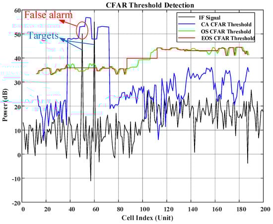
Figure 4.
Simulation results of three CFAR algorithms.
3.2. Improved Signal Processing Method for Filling in Data
After applying the EOS-CFAR algorithm, the antenna array collects data exclusively from the monitored targets, significantly reducing data redundancy. However, when multiple targets are present, the collected signals become discontinuous in the azimuth direction. In addition, each antenna array loop time is determined by the activation time of the antenna array, which leads to irregular antenna loops and subsequent data anomalies when applying the imaging algorithm. The proposed method interpolates and supplements the acquired virtual aperture signals to construct complete signals. The method uses both the periodic signal and the virtual aperture numbers to supplement the IF signal data to ensure compensated signal acquisition and subsequent image processing.
The data collected by the ADC include both the antenna switching signal marker and the pulse trigger’s output signal. The echo signals are then rearranged according to the correspondence between the physical array element combination T/R and the number of virtual array elements V. The echo signals are rearranged in the order of the virtual array elements, from 1 to 44, to form a data matrix for the virtual array elements. Then, the antenna switching signal marker is processed according to the order in which the virtual arrays are arranged. The complete signal of the virtual array antenna can be determined from the value of and a self-defined threshold A. The judgment formulas are and .
The antenna switching signal marker is segmented into rows and columns, creating a matrix of segmented signals of varying sizes. Each combination of virtual arrays has a fixed acquisition time, which can be multiplied by the acquisition frequency to determine the amount of data acquired during each radar sampling period. The signals in a radar scanning period are cut according to the trigger signal matrix. These matrices are matched to the previous switching signal markers . Subsequently, the signal matrices of different lengths are aligned according to the positions of the switching signal markers . The switching signal markers reorganize and calibrate each row of the signal matrix to obtain a signal matrix of uniform length. The specific operation is shown in Figure 5.
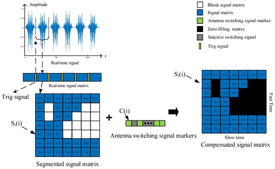
Figure 5.
Schematic diagram of signal matrix reorganization.
In the signal matrix, blank areas represent the virtual antenna array elements that fail to detect the target during the loop process of the antenna array. The blue regions represent the portion of the array element that is turned on during the loop process of the antenna array. The acquired signals are checked against the array elements one by one, with the fast time representing the period of data acquisition for a single array element and the slow time denoting the antenna array scanning period. The black regions indicate complementary zero-filling of the matrix in order to reconstruct the complete echo signal matrix for a radar scanning period.
3.3. Coherent Background Subtraction Based on Recursive Averaging
After zero-filling the data, the radar signals still exhibit significant background noise. We perform background subtraction on the time-domain signal to solve this problem. The background subtraction method is used for calibration, which involves selecting a region with significant and stable clutter interference in the horizontal direction as the background value. The average value of all signal matrix values in this region is calculated and subtracted from the channel values of the signal matrix, eliminating leakage clutter and enhancing the usefulness of the target reflection signal. Meanwhile, directly processing the time-domain signal improves the data-processing speed.
Environmental background noise is often highly dynamic, especially in a variable environment or a complex background of clutter, and may change substantially over time. In this case, simple background subtraction processing cannot accurately estimate the background value, resulting in the target signal not being effectively separated. In this study, we adopted the background subtraction method based on the adaptive recursive method. First, the background model can be obtained based on the received signal of the radar:
where is the current echo signal, is the background component, and is the sparse target component. Then, the echo data at each moment are regarded as a superposition of the background and the sparse target component, and real-time background modeling is carried out via the weighted averaging of the target signal at the current moment and the background estimation at the previous moment. Then, background subtraction is used to effectively separate the background from the sparse target component. The objective is to eliminate background clutter and retain the target features. The mathematical model of the background updating process in the adaptive recursive method is usually expressed as follows:
where is the background value at the current moment, is the echo signal at the current moment, is a weighting factor of 0 or 0.5 [41], and is the background value at the previous moment. To address the system’s operational requirements for rapid imaging and the constrained computational resources in edge devices, a dynamic adjustment mechanism for parameter is implemented based on the background environmental complexity. In scenarios characterized by minimal background variation (for example, under stable illumination conditions in experimental settings), is assigned a value of 0. This configuration suspends background modeling processes, thereby reducing the computational load during data-processing operations. In contrast, under dynamic environmental conditions that exhibit significant background fluctuations (for example, adverse environmental scenarios), is set to 0.5 to enable real-time background updating. This adaptive framework ensures the continuous optimization of image quality while maintaining system efficiency. To verify the effectiveness and robustness of the method, simulations were conducted. The signal-to-noise ratios of the processing results of this method and the traditional background subtraction method, which only takes the empty environment as the background, were tested by introducing background noise that changes over time. The results of the experiment are shown in Figure 6.
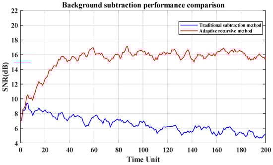
Figure 6.
The results of background subtraction performance comparison.
The comparison results show that, as the background noise intensity increases, the signal-to-noise ratio of the results obtained using the traditional background subtraction method shows a decreasing trend, while that of the method proposed in this paper shows an increasing trend and tends to stabilize. The results of the proposed approach are better than those of the traditional method. Next, we conducted a set of simulations to verify the feasibility of the background subtraction algorithm with the following simulation parameters: the number of targets is four; each target corresponds to a signal strength value of −60 dBm, −65 dBm, −70 dBm, or −80 dBm; and the background noise follows a Gaussian distribution with a mean power of −90 dBm. Figure 7 shows the results of the simulation.
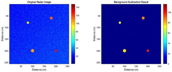
Figure 7.
Simulation results using the proposed method.
The simulation results show that the original radar imaging has high background noise, which becomes cleaner after coherent background subtraction. In contrast to the traditional background clipping algorithm, where the previous background image is directly subtracted from the latest image, the proposed background subtraction method is based on time-domain signal data without repeating the imaging operation, which improves the quality of radar imaging while ensuring the efficiency of data processing. This method is suitable for low-cost, miniaturized, and low-complexity radar usage scenarios.
4. Improved Calculation Method for Fast Target Imaging
The Omega-K algorithm, also known as the range migration algorithm (RMA) [42,43,44], is widely regarded as one of the most effective SAR imaging algorithms. We employ the TensorFlow-optimized Omega-K algorithm for radar imaging based on array radar signals. FFT is a key step in the radar imaging process, and the clarity of radar images can be improved by optimizing the radar signal phase. For the radar signal phase optimization, we use the improved Adam Optimizer to optimize the radar signal phase to keep the phase smooth, which significantly improves the clarity of the radar image and the accuracy of target detection. First, we utilize TensorFlow to create tensor variables to store phase data. The radar phase is then optimized using an improved Adam Optimizer by incorporating a self-learning rate mechanism.
In radar imaging, TensorFlow can greatly improve the computational speed of FFT and Stolt interpolation by optimizing GPUs to process large data in parallel. Because FFT and Stolt interpolation are widely used in the Omega-K-based imaging algorithm, we apply an optimized computational framework based on TensorFlow that utilizes parallel GPU operations to implement FFT and Stolt interpolation in radar imaging to increase computational efficiency and speed up processing. Specifically, we implement batch FFTs using TensorFlow’s tf.signal.fft2d and CUDA’s perceptual memory allocation. The FFT, Stolt interpolation, and IFFT computations are accelerated by the parallel processing capability provided by the improved TensorFlow/GPU-based method. The specific algorithm steps are shown in Figure 8.
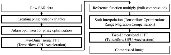
Figure 8.
The imaging algorithm flowchart.
The SAR target echo signal containing the distance and orientation dimensions is [45]
where is the signal amplitude, and are the fast time and slow time, is the beam center deviation time, and are the distance and azimuth envelopes, is the radar center frequency, is the chirp distance tuning frequency, and is the instantaneous slant distance.
The phase information of the signal is an important factor in radar imaging and target detection. The proposed Adam optimizer compensates the phase of the signal to improve the phase smoothness and reduce the blurring of the image due to phase error. The phase optimization formula is as follows:
where is the current phase value, is the phase value after iteration, is the learning rate, and are the gradient momentum estimate and the estimate of the gradient square in the Adam optimizer, and is . Then, the SAR target echo signal (9) is converted to the 2D frequency domain using the 2D FFT to obtain
After the signal is converted to the 2D frequency domain, the next step is to apply Stolt interpolation and the inverse 2D FFT. This operation converts the frequency-domain signal back into the spatial domain, reconstructing the radar image. Once the image reconstruction is complete, the final step is to perform image compression as required to reduce the data size.
In order to verify the feasibility of the proposed imaging algorithm, we conducted simulations. Both a single-target scenario and a five-target scenario were simulated. The configurations for the single-target and five-target scenes are illustrated in Figure 9a and Figure 9b, respectively, with the corresponding imaging results presented in Figure 9c and Figure 9d.
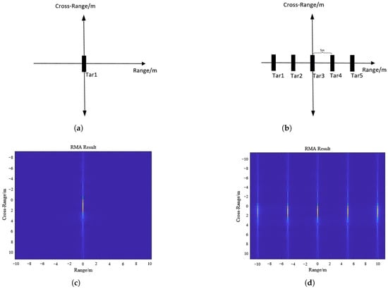
Figure 9.
(a) Position of one target. (b) Positions of five targets. (c) Imaging result for one target. (d) Imaging result for five targets.
In the simulation results, the location and shape of the targets in the image are consistent with the simulation objectives, which verifies the feasibility of the radar imaging algorithm.
In this study, Adam is extended to the phase domain to reduce the phase blur in imaging by limiting the momentum of the phase gradient. The improved algorithm significantly improves the target edge sharpness while maintaining phase continuity. We validated the proposed Adam’s phase optimization method by performing simulations, and the imaging results are shown in Figure 10.
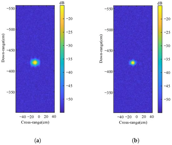
Figure 10.
(a) Imaging results before Adam optimization. (b) Imaging results after Adam optimization.
In Figure 10a the target image is surrounded by sidelobes that cause blurred scattering, but in Figure 10b, the Adam optimizer has been used to optimize the phase, which results in a more focused and clearer target image, indicating that phase optimization effectively improves the resolution of the image. The results of Adam optimization can be more concretely demonstrated by comparing the peak-to-sidelobe ratio (PSLR) to the integrated sidelobe ratio (ISLR) [46].
Table 2 shows the results of the PSLR and ISLR comparison. The optimized method improves both the PSLR (+5 dB) and ISLR (+0.7 dB), validating its effectiveness in suppressing sidelobes and enhancing image sharpness. These results are consistent with visual observations of the images.
Table 2.
PSLR and ISLR comparison results.
5. Results of Experiments
In this section, we will first introduce the experimental platform, including hardware equipment and experimental parameters. Next, we will present a series of experiments conducted to verify the feasibility of our proposed system and method, confirming its efficiency through comparative analysis.
The proposed antenna array is a combination of 13 transmitting antennas and 8 receiving antennas, and the structure is shown in Figure 11.
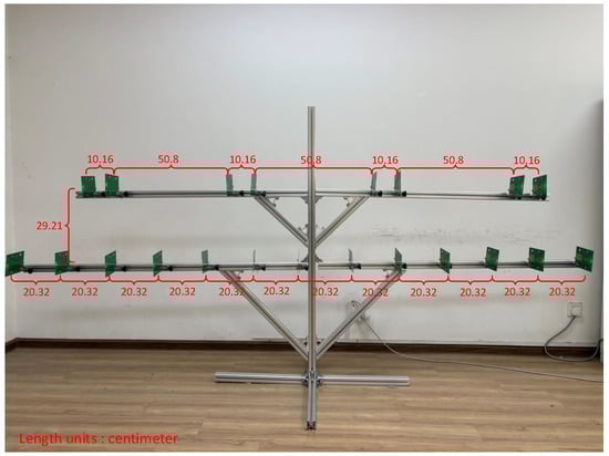
Figure 11.
The structure of antenna array radar.
All distances labeled in the figure are in centimeters (cm). The array antennas form a virtual aperture spacing of 5.08 cm. All the antennas used are equivalent Vivaldi antennas, and the designed frequency range is 1.5 to 4 GHz. In our operating frequency range, the antenna gain is around 6.58 dB; the E-plane has a 3 dB beamwidth of approximately 68.22°; and the H-plane has a 3 dB beamwidth of approximately 125°. The orientation of the beam maximum of Vivaldi antenna is characterized by radiation in the end-fire direction [47]. The proposed radar antenna and structure of the FMCW radar system are shown in Figure 12 and Figure 13.

Figure 12.
Top layer and bottom layer of the radar antenna.
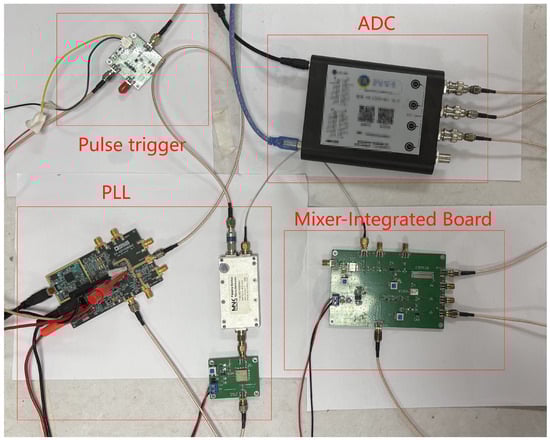
Figure 13.
A picture of the structure of the radar system.
The proposed structure of the FMCW radar system is shown in Figure 13. The modulating signal is a continuous triangular wave. The sweep parameters are shown in Table 3.
Table 3.
Sweep parameter settings.
The software environment of the experiment was a Debian GNU/Linux 11 operating system (Intel(R) Xeon(R) CPU E5-2620 v4 @ 2.10GHz, Intel Corporation, Santa Clara, CA, USA), the system memory was 32 GB, and the GPU was an NVIDIA Quadro P5000 (GP104GL, NVIDIA Corporation, Santa Clara, CA, USA). The simulation software was MATLAB R2022b.
The effectiveness of the proposed antenna switching algorithm based on the EOS-CFAR algorithm in reducing data wastage is assessed by analyzing the percentage of valid data among all data. In the unit period, the higher the proportion of effective data to all collected data, the greater the amount of data used. The degree of data validity can be expressed as
where T is the antenna array scanning period, is the activation time of the array element combination, D is the number of virtual array elements occupied by the target, and E is the number of virtual array elements.
The traditional array antenna switching algorithm cycles in a fixed order, which is the order of array elements. In contrast, the proposed antenna switching algorithm turns on only the combinations of array elements that can detect the target and turn off the remaining combinations. The results for data utilization are shown in Table 4.
Table 4.
The results for data utilization.
In the above table, the time is 1 scanning period of the antenna array, the number of targets is 2, the number of antenna beams occupied by the targets is 14, and the total number of array elements is 44. It can be seen that the improved switching algorithm improves effective data acquisition by 42.86% compared to the traditional switching algorithm.
Next, we performed array element imaging processing for real targets, which were treated as experimental objects. We performed an outdoor experiment at a site with flat concrete ground, with no obvious interference with external objects on the site.
First, we performed radar imaging directly on the acquired radar signals without any background subtraction processing, and the imaging results are shown in Figure 14a,c. Figure 14a shows the imaging results of the experimental scene in Figure 15a, and Figure 14c shows those of the scene in Figure 15a. Two targets can be seen in the images, and the imaging results are consistent with the detected target positions in the scene. However, due to the cross-range sidelobe and the non-ideal characteristics of the system hardware and environmental factors [12], the image contains substantial clutter interference, resulting in a lack of clarity.
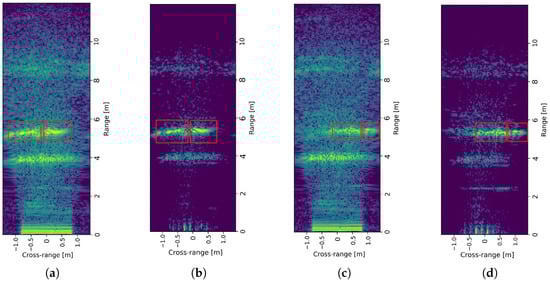
Figure 14.
(a) The initial results of an experiment with a 1 m target spacing. (b) The final results of an experiment with a 1 m target spacing. (c) The initial results of an experiment with a 0.5 m target spacing. (d) The final results of an experiment with a 0.5 m target spacing.
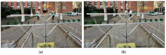
Figure 15.
(a) The experiment with a target spacing of 1 m. (b) The experiment with a target spacing of 0.5 m.
We then processed the acquired radar signals with background subtraction to obtain the radar images in Figure 14b,d. These images clearly show the two targets, and the clutter in the images is effectively suppressed. The imaging results are consistent with the detected target positions in the scene, thus validating the effectiveness and accuracy of the system and method.
Finally, we compared the TensorFlow-based GPU-accelerated method with a CPU-accelerated method and a method without GPU or CPU acceleration (NumPy); we evaluated the computation time of FFT operations and Stolt interpolation for different data volumes. Figure 16 shows the computation times of the three methods.
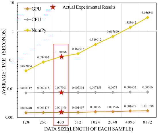
Figure 16.
The computation times of the three methods.
The experimental results show that the TensorFlow-based GPU-accelerated method significantly improves the processing speed of radar imaging. In particular, for large datasets, GPU acceleration reduces the computation time and improves the overall performance compared to the traditional CPU and NumPy methods. Moreover, it can be seen that the traditional NumPy computation time increases as the radar data volume increases. However, when the data volume is large, the computation time of the CPU- and GPU-based methods is not significantly affected by the increase in data volume. In actual experiments, the time required for the GPU-based processing of radar data is about 0.0015 s, which is one percent of the traditional NumPy computation time. Furthermore, GPU processing significantly reduces the computation time compared to the CPU approach. Therefore, the TensorFlow-based GPU-accelerated method significantly improves the processing speed of radar imaging.
In summary, the proposed array antenna achieves 2.15 times higher azimuthal resolution compared to the traditional ULA. The proposed antenna switching method based on the EOS-CFAR improves effective data acquisition by 42.86%, and the proposed recursive averaging-based background subtraction method improves the signal-to-noise ratio (SNR) by 10–15 dB in a dynamic noise environment compared to the traditional background subtraction method. Finally, the proposed TensorFlow-optimized Omega-K imaging method improves image clarity by about 30% compared to the traditional imaging method, and the imaging speed is greatly improved.
6. Conclusions
This paper proposes an array-radar-based FMCW SAR imaging system and fast detection method for targets. The system employs an equivalent 44-element virtual antenna array to improve azimuthal resolution. The improved array switching control algorithm based on the EOS-CFAR effectively reduces the echo data volume, which solves the problem of the large data volume in the traditional radar switching control method. The anomalies caused by data discontinuity are corrected by performing interpolation and compensation. Background subtraction based on the recursive averaging of time-domain data provides the basis for subsequent higher-quality imaging. In addition, the TensorFlow-accelerated Omega-K algorithm and the improved Adam Optimizer are introduced into the imaging algorithm to further enhance the image clarity and the imaging speed of the radar. The results of real-world experiments verify that these methods are feasible and effective and that the system is able to detect targets quickly. Dense clutter can saturate the subarray partitioning of the EOS-CFAR, potentially degrading its performance. The adaptive parameter of recursive averaging-based background subtraction methods may lack universal optimality under highly dynamic clutter conditions. For moving targets, we propose enhancing the Omega-K algorithm with velocity-adaptive motion compensation. This approach will utilize GPU-accelerated Kalman filtering for real-time updates, ensuring the accurate tracking of dynamic targets. In the future, we will further improve the algorithms and hardware performance and apply them to target detection in more complex environments.
Author Contributions
Conceptualization, C.W. and P.G.; methodology, C.W. and P.G.; validation, C.W., P.G., D.F., P.D., W.Z. and Y.C.; formal analysis, C.W. and P.G.; investigation, P.G.; resources, C.W. and P.G.; data curation, P.G. and D.F.; writing—original draft preparation, P.G.; writing—review and editing, C.W., D.F., P.D., W.Z. and Y.C.; visualization, P.G. All authors have read and agreed to the published version of the manuscript.
Funding
This work is partly supported by the Natural Science Foundation of Henan Province under Grant 222300420295, by the Henan Province Science and Technology Research Project under Grant 232102210050, by the University–Industry Collaborative Education Program under Grant 231103873161120, by Zhengzhou City’s Key Research and Development Special Project under Grant 20230071A, and partly by the Collaborative Innovation Major Project of Zhengzhou under Grant 20XTZX06013.
Data Availability Statement
Data are contained within the article.
Acknowledgments
This article is a revised and extended version of the paper entitled “A Low-Complexity FMCW-SAR Imaging System and Moving Target Detection Method”, which was originally presented at the Third International Conference on Algorithms, Microchips, and Network Applications (AMNA 2024), SPIE, Volume 13171, Article 131710Z [1]. We are sincerely grateful to the original conference publication for providing the foundational hardware design.
Conflicts of Interest
The authors declare no conflicts of interest.
References
- Wang, C.; Feng, D.; Guo, P.; Chang, W.; Guo, J.; Duan, P.; Cao, Y. A Low-Complexity FMCW-SAR Imaging System and Moving Target Detection Method. In Proceedings of the Third International Conference on Algorithms, Microchips, and Network Applications (AMNA 2024), Jinan, China, 8–10 March 2024; Volume 13171, p. 131710Z. [Google Scholar] [CrossRef]
- Kim, M.; Kim, S. Real-Time High-Resolution SAR Imaging Using a Commercial W-Band Radar and Rail System. In Proceedings of the 2024 24th International Conference on Control, Automation and Systems (ICCAS), Jeju, Republic of Korea, 29 October–1 November 2024; pp. 443–445. [Google Scholar] [CrossRef]
- Ling, Q.; Ma, J.; Ni, T.; Huang, P.; Xia, X.G.; Liu, Y.; Liu, Z.; Liu, X. Imaging Approach for FMCW Synthetic Aperture Radar Sensor Using Modified ω-K Method. IEEE Sens. J. 2024, 24, 41243–41250. [Google Scholar] [CrossRef]
- Peng, J.; Kai, L.; Zheng, X.; Gao, J. Research and Implementation of Mm-Wave SAR Near-Field Imaging System. In Proceedings of the 2024 5th International Symposium on Computer Engineering and Intelligent Communications (ISCEIC), Wuhan, China, 8–10 November 2024; pp. 21–26. [Google Scholar] [CrossRef]
- Zhang, Y.; Tang, H.; Wu, Y.; Wang, B.; Yang, D. FMCW Radar Human Action Recognition Based on Asymmetric Convolutional Residual Blocks. Sensors 2024, 24, 4570. [Google Scholar] [CrossRef] [PubMed]
- Song, Y.; Hu, J.; Chu, N.; Jin, T.; Zhang, J.; Zhou, Z. Building Layout Reconstruction in Concealed Human Target Sensing via UWB MIMO Through-Wall Imaging Radar. IEEE Geosci. Remote Sens. Lett. 2018, 15, 1199–1203. [Google Scholar] [CrossRef]
- Yamada, H.; Kobayashi, T.; Yamaguchi, Y.; Sugiyama, Y. High-resolution 2D SAR imaging by the millimeter-wave automobile radar. In Proceedings of the 2017 IEEE Conference on Antenna Measurements & Applications (CAMA), Tsukuba, Japan, 4–6 December 2017; pp. 149–150. [Google Scholar]
- Wang, W.; Liang, D.; Wang, Z.; Yu, H.; Liu, Q. Design and Implementation of a FPGA and DSP Based MIMO Radar Imaging System. Radioengineering 2015, 24, 518–526. [Google Scholar] [CrossRef]
- Ting, J.-W.; Oloumi, D.; Rambabu, K. FMCW SAR System for Near-Distance Imaging Applications—Practical Considerations and Calibrations. IEEE Trans. Microw. Theory Tech. 2018, 66, 450–461. [Google Scholar] [CrossRef]
- Pan, Y.; Xu, J. Phase Noise Analysis of Fractional-N PLL Based Frequency Ramp Generator for FMCW Radar. In Proceedings of the 2015 Asia-Pacific Microwave Conference (APMC), Nanjing, China, 6–9 December 2015; pp. 1–3. [Google Scholar] [CrossRef]
- Shen, Y.; Wang, Z.; Du, X.; Mo, Z.; Hua, Y. A Ku-band Frequency Synthesizer Based on PLL. In Proceedings of the 2020 International Conference on Microwave and Millimeter Wave Technology (ICMMT), Shanghai, China, 20–23 September 2020; pp. 1–3. [Google Scholar] [CrossRef]
- Charvat, G.L. Small and Short-Range Radar Systems, 1st ed.; CRC Press: Boca Raton, FL, USA, 2014. [Google Scholar] [CrossRef]
- Lee, S.; Joo, J.; Choi, J.; Kim, W.; Kwon, H.; Lee, S.; Kwon, Y.; Jeong, J. W-Band Multichannel FMCW Radar Sensor With Switching-TX Antennas. IEEE Sens. J. 2016, 16, 5572–5582. [Google Scholar] [CrossRef]
- Ding, J.; Ma, W.; Wang, Z.; Kang, H.; Wang, M. Automotive radar 4D Point-cloud Imaging with 2D Sparse Array. In Proceedings of the 2021 CIE International Conference on Radar (Radar), Haikou, China, 15–19 December 2021; pp. 2838–2842. [Google Scholar]
- Guetlein, J.; Bertl, S.; Kirschner, A.; Detlefsen, J. Switching scheme for a FMCW-MIMO radar on a moving platform. In Proceedings of the 2012 9th European Radar Conference, Amsterdam, The Netherlands, 31 October–2 November 2012; pp. 91–94. [Google Scholar]
- Hu, X.; Lu, M.; Li, Y.; Wang, Y. Motion compensation for TDM MIMO radar by sparse reconstruction. Electron. Lett. 2017, 53, 1604–1606. [Google Scholar] [CrossRef]
- Cui, G.; Wang, S.; Wang, Y.; Liu, Z.; Yuan, Y.; Wang, Q. Preceding Vehicle Detection Using Faster R-CNN Based on Speed Classification Random Anchor and Q-Square Penalty Coefficient. Electronics 2019, 8, 1024. [Google Scholar] [CrossRef]
- Sun, S.; Wang, J. Ship Detection in SAR Images Based on Steady CFAR Detector and Knowledge-Oriented GBDT Classifier. Electronics 2024, 13, 2692. [Google Scholar] [CrossRef]
- Ma, B.; Yang, H.; Yang, J. Ship Detection in Spaceborne SAR Images under Radio Interference Environment Based on CFAR. Electronics 2022, 11, 4135. [Google Scholar] [CrossRef]
- Hou, B.; Chen, X.; Jiao, L. Multilayer CFAR Detection of Ship Targets in Very High Resolution SAR Images. IEEE Geosci. Remote Sens. Lett. 2015, 12, 811–815. [Google Scholar] [CrossRef]
- Xu, C.; Li, Y.; Ji, C.; Huang, Y.; Wang, H.; Xia, Y. An Improved CFAR Algorithm for Target Detection. In Proceedings of the 2017 International Symposium on Intelligent Signal Processing and Communication Systems (ISPACS), Xiamen, China, 6–9 November 2017; pp. 883–888. [Google Scholar] [CrossRef]
- Rittiplang, A.; Phasukkit, P. 1-Tx/5-Rx Through-Wall UWB Switched-Antenna-Array Radar for Detecting Stationary Humans. Sensors 2020, 20, 6828. [Google Scholar] [CrossRef] [PubMed]
- Yang, X.; Zheng, Y.R.; Ghasr, M.T.; Donnell, K.M.; Zoughi, R. Microwave Synthetic Aperture Radar Imaging Using Sparse Measurement. In Proceedings of the 2016 IEEE International Instrumentation and Measurement Technology Conference Proceedings, Taipei, Taiwan, 23–26 May 2016; pp. 1–5. [Google Scholar] [CrossRef]
- Koklu, F.H. High Numerical Aperture Subsurface Imaging. Ph.D. Thesis, Boston University, Boston, MA, USA, 2010. [Google Scholar]
- Shen, W.; Lin, Y.; Li, Y.; Hong, W.; Wang, Y. Moving Targets Artifacts Removal in Multiaspect SAR Imagery Based on Logarithm Background Subtraction. IEEE J. Miniaturization Air Space Syst. 2023, 4, 62–69. [Google Scholar] [CrossRef]
- Hernández-Burgos, S.; Gibert, F.; Broquetas, A.; Kleinherenbrink, M.; De la Cruz, A.F.; Gómez-Olivé, A.; García-Mondéjar, A.; Aparici, M.R. A Fully Focused SAR Omega-K Closed-Form Algorithm for the Sentinel-6 Radar Altimeter: Methodology and Applications. IEEE Trans. Geosci. Remote Sens. 2024, 62, 5206016. [Google Scholar] [CrossRef]
- Liang, W.; Li, C.; Yang, S.; Shi, Y.; Luo, Z.; Qiu, R. A Novel Block Focused Omega-K Algorithm for Millimetre-Wave Radar Imaging. In Proceedings of the 2023 International Conference on Neuromorphic Computing (ICNC), Wuhan, China, 15–17 December 2023; pp. 303–312. [Google Scholar] [CrossRef]
- Wang, Z.; Li, T.; Tong, C. A Fast Simulation Method in Range-Doppler Domain for Airborne Radar Clutter. In Proceedings of the 2023 IEEE 7th International Symposium on Electromagnetic Compatibility (ISEMC), Hangzhou, China, 20–23 October 2023; pp. 1–4. [Google Scholar]
- Zhang, X.; Yang, Z.; Zhang, Y.; Li, X.; Zhao, X. Region Weighted Cross-Correlation Back Projection Imaging Algorithm for Stepped Frequency Ground Penetrating Radar. In Proceedings of the 2023 5th International Academic Exchange Conference on Science and Technology Innovation (IAECST), Guangzhou, China, 8–10 December 2023; pp. 380–385. [Google Scholar]
- Lei, H.Y.; Xiong, J.T.; Wei, S.J.; Lou, X.Y.; Zhang, T. Millimetre-wave automotive radar imaging enhancement via doppler beam sharpening. In Proceedings of the IGARSS 2023-2023 IEEE International Geoscience and Remote Sensing Symposium, Pasadena, CA, USA, 16–21 July 2023; pp. 4403–4406. [Google Scholar]
- Holder, M.; Eberspächer, M.; Waldschmidt, C. Radar imaging device using prism shaped aperture. In Proceedings of the 2024 Kleinheubach Conference, Miltenberg, Germany, 24–26 September 2024; pp. 1–4. [Google Scholar]
- Meng, D.; Hu, Y.; Tao, S.; Rui, S.; Li, X. Airborne SAR real-time imaging algorithm design and implementation with CUDA on NVIDIA GPU. J. Radars 2013, 2, 481–491. [Google Scholar] [CrossRef]
- Feng, F.; Li, Y.; Ye, X.; Shi, S.; Li, S. Design of Radar Imaging Processing Platform Based on the Architecture with Digital Signal Acquisition Board and GPU. In Proceedings of the 2021 2nd China International SAR Symposium (CISS), Shanghai, China, 3–5 November 2021. [Google Scholar]
- Forsten, H. “Synthetic Aperture Radar Imaging” [EB/OL]. 13 August 2019. Available online: https://hforsten.com/synthetic-aperture-radar-imaging.html (accessed on 23 January 2024).
- Liu, L.; Fan, J.; Liu, Q. VCO Based Design of Low Phase Noise Microwave Frequency Synthesizer. In Proceedings of the 2015 IEEE 16th International Conference on Communication Technology (ICCT), Hangzhou, China, 18–20 October 2015; pp. 248–251. [Google Scholar] [CrossRef]
- Charvat, G.L.; Kempel, L.C.; Rothwell, E.J.; Coleman, C.M.; Mokole, E.L. A Through-Dielectric Ultrawideband (UWB) Switched-Antenna-Array Radar Imaging System. IEEE Trans. Antennas Propag. 2012, 60, 5495–5500. [Google Scholar] [CrossRef]
- Charvat, G.L.; Kempel, L.C.; Rothwell, E.J.; Coleman, C.M.; Mokole, E.L. An Ultrawideband (UWB) Switched-Antenna-Array Radar Imaging System. In Proceedings of the 2010 IEEE International Symposium on Phased Array Systems and Technology, Waltham, MA, USA, 12–15 October 2010; pp. 543–550. [Google Scholar]
- Kim, H.; You, S.; Jeong, B.J.; Byun, W. Azimuth angle resolution improvement technique with neural network. In Proceedings of the 2020 International Conference on Information and Communication Technology Convergence (ICTC), Jeju Island, Republic of Korea, 21–23 October 2020; pp. 1384–1387. [Google Scholar]
- Yang, W.; Ai, M.; Wang, F.; Fu, Q.; Chai, M.; Zhang, Y. Multi Target Detection Algorithm for Millimeter Wave Radar Based on Improved OS-CFAR. In Proceedings of the 2023 3rd International Symposium on Computer Technology and Information Science (ISCTIS), Chengdu, China, 16–18 June 2023; pp. 442–447. [Google Scholar]
- Rohling, H. Radar CFAR thresholding in clutter and multiple target situations. IEEE Trans. Aerosp. Electron. Syst. 1983, 4, 608–621. [Google Scholar] [CrossRef]
- Kamel, H.; Ali, S.E.E.; Shehata, M.G. Detection Boosting of Low Signal-to-Noise Ratio Targets Using A Proposed Adaptive Filter Technique. In Proceedings of the 2024 41st National Radio Science Conference (NRSC), New Damietta, Egypt, 16–18 April 2024; Volume 1, pp. 143–150. [Google Scholar]
- Cumming, I.G.; Wong, F.H. Digital Processing of Synthetic Aperture Radar Data: Algorithms and Implementation. Artech House 2005, 1, 108–110. [Google Scholar]
- Shi, G.; Zou, Y.; Jin, Y.; Cui, X.; Li, W.J. Towards HMM based human motion recognition using MEMS inertial sensors. In Proceedings of the 2008 IEEE International Conference on Robotics and Biomimetics, Bangkok, Thailand, 22–25 February 2009; pp. 1762–1766. [Google Scholar] [CrossRef]
- Guo, S.; Dong, X. Modified Omega-K algorithm for ground-based FMCW SAR imaging. In Proceedings of the 2016 IEEE 13th International Conference on Signal Processing (ICSP), Chengdu, China, 6–10 November 2016; pp. 1647–1650. [Google Scholar] [CrossRef]
- Li, R.; Yan, H.; Wu, C.; Zhao, R.; Zhang, J.; Zhu, D. Low-Flying Moving Target Detection and Imaging Algorithm of Spaceborne SAR Based on Two-Dimensional Velocity Search. In Proceedings of the 2022 14th International Conference on Signal Processing Systems (ICSPS), Zhenjiang, China, 18–20 November 2022; pp. 437–443. [Google Scholar]
- Benmeziane, B.; Baudais, J.Y.; Méric, S.; Cinglant, K. Comparison of ZF and MF filters through PSLR and ISLR assessment in automotive OFDM radar. In Proceedings of the 2021 18th European Radar Conference (EuRAD), London, UK, 5–7 April 2022; pp. 193–196. [Google Scholar]
- Carroll, J.; Paparisto, G.; Vye, D. Theoffee-Canadar Redesigned as an Inexpensive RF PCB [Application Notes]. IEEE Microw. Mag. 2016, 17, 62–74. [Google Scholar] [CrossRef]
Disclaimer/Publisher’s Note: The statements, opinions and data contained in all publications are solely those of the individual author(s) and contributor(s) and not of MDPI and/or the editor(s). MDPI and/or the editor(s) disclaim responsibility for any injury to people or property resulting from any ideas, methods, instructions or products referred to in the content. |
© 2025 by the authors. Licensee MDPI, Basel, Switzerland. This article is an open access article distributed under the terms and conditions of the Creative Commons Attribution (CC BY) license (https://creativecommons.org/licenses/by/4.0/).