1. Introduction
Advanced Driver Assistance Systems (ADASs) improve vehicle control during dangerous manoeuvres, distractions, or high-risk situations. Standardising ADASs and introducing self-driving cars will significantly alter driving by enhancing steering, acceleration, braking, and safety [
1].
Recent advancements in intelligent transportation systems and autonomous vehicle technologies have significantly contributed to the development of vehicle control mechanisms aimed at improving vehicular stability, trajectory accuracy, and lane-keeping performance. Within this domain, the ability to accurately model and predict driver behaviour is essential for designing adaptive assistance systems that respond effectively to varying road geometries, environmental conditions, and individual driving styles. Studies have demonstrated that driver behaviour is influenced by multiple factors, including cognitive workload, visual perception, reaction time, and prior driving experience, all of which play a role in how drivers interact with path-tracking algorithms.
The driver’s understanding of the geometric properties of a road can result in variations in driving behaviour, influenced by the specific type and characteristics of the road [
2,
3,
4]. Vehicle dynamics provide a framework for the determination of certain road geometry properties by means of inertial measurements from vehicles. These data sources have been shown to be effective in identifying road characteristics, which can then be used to infer driving behaviour and indirectly assess road geometry [
5].
In this work, an intelligent follow-through control of a lead vehicle is designed that uses road geometry to optimise acceleration and steering. A 3-degree-of-freedom vehicle model is used. Deep reinforcement learning (DRL) is applied for both longitudinal and lateral control. The proposed driver assistance system incorporates the influence of road curvature by integrating features derived from road geometry, such as longitudinal and lateral acceleration perceived by the driver when cornering [
6]. The idealised Ackerman yaw rate and roll coefficient are also included in the DRL control cost function. The proposed design uses environmental observations such as vehicle speed and speed error with respect to the preceding vehicle; its integral; and the vehicle lateral deviation error, yaw rate error, and its derivatives and integrals. The outputs are acceleration and steering angle values for vehicle control. This approach improves driving safety by addressing scenarios where excessive speed in corners could compromise safety.
The control system will be applied in the context of path following, where the maintenance of a safe distance from the leader vehicle is critical [
7]. Preliminary results are promising, suggesting that the system can be integrated into vehicles equipped with inertial measurement systems to improve road safety, decrease traffic accidents, and reduce driver fatigue [
8].
In speed control systems, driver models are essential [
9]. Traditionally, supervised learning methods and rule-based approaches have been used to create these models [
10,
11]. Authors [
12] present an innovative hierarchical framework combining analytical and neural models based on physical principles. This approach enables online planning and tracking of minimum-time manoeuvres for vehicles with partially unknown parameters. Recently, reinforcement learning, particularly deep learning-based methods, has emerged as an effective solution for decision-making across various domains [
13]. For vehicle applications, deep learning has been used to control simulated cars [
14], while optimal control strategies have been applied to autonomous underwater vehicle navigation [
15]. Hybrid models combining machine learning and kinematic approaches have also been proposed for automated vehicle car-following control [
16]. Additionally, reinforcement learning methods have been employed to develop safe velocity control for autonomous vehicles (AVs), considering interactions with following vehicles [
17] as well as human-like car-following models [
18]. A recent data-driven adaptive cruise control application using DRL combines several objectives, including safety, passenger comfort, and efficient road use [
19]. In [
20], this study proposes a Provisional Cross-layered Deep Q-Network (PC-DQN) for autonomous driving path planning, improving stability and efficiency using global path guidance and fuzzy control. Experiments in CARLA confirm its superior performance over existing methods.
This study differentiates from those by taking into account and emphasising the influence of specific road geometry features, particularly road curvature, on driving dynamics.
The main contribution of this study is the approach inspired by the perception of road geometry, which extracts its influence from the curvature of the road by inferring the acceleration perceived by the vehicle occupants. The vehicle control system uses this lateral acceleration, obtained from the lateral acceleration of the vehicle itself and that induced by the road, to learn longitudinal control. On the other hand, to learn lateral control, the concept of the ideal or theoretically ideal yaw rate is included, so that the vehicle does not experience understeering or oversteering problems when cornering at excessive speeds, thus preventing skidding during driving, as well as the introduction of the anti-roll coefficient to avoid this phenomenon. The aim is to keep the vehicle within acceptable levels of acceleration, jerk and steering angle in order to maintain both safety and comfort, with pleasant sensations perceived or felt by the vehicle’s occupants.
The main contributions of this work can be summarised as follows:
- -
An intelligent system has been designed and implemented in simulation that incorporates the acceleration perceived by vehicle occupants into the longitudinal control, with the goal of making driving more comfortable. This driving criterion has been included in the cost function of the RL system for longitudinal control.
- -
The system also incorporates other aspects that make driving safer in the RL function of the vehicle lateral control, such as anti-rollover, anti-skid, etc.
- -
This system does not require historical data because the system learns from its errors. Actual historical measurements are usually scarce or non-existent.
- -
Very few measurements are required, and all cars are currently equipped with the necessary sensors to obtain them.
The paper is organised as follows:
Section 2 reviews related works.
Section 3 introduces vehicle dynamics for the vehicle control system.
Section 4 discusses the deep reinforcement learning system for control.
Section 5 presents the results. Finally,
Section 6 outlines findings and future research.
2. Background and Related Works
Although significant progress has been made in the development of car-following models in transportation research, these models still face challenges that limit their effectiveness in dynamic and complex driving environments. Traditional car-following models depend on a limited set of parameters and empirical calibration, which may not have the flexibility to handle diverse transportation environments, affecting their generalisability. Data-based approaches capture complex vehicle interactions but often rely on extensive historical datasets, possibly resulting in less optimal performance due to biases or the use of non-representative driving behaviour samples.
Achieving a specific objective in autonomous vehicle navigation requires a well-defined planning phase. If the planning occurs within configuration space, the result is typically represented as a geometric path, which can be either holonomic or non-holonomic. Path following bridges the reference geometric path and low-level vehicle control. Various studies have explored this concept, including the pure pursuit algorithm [
21], exponential control laws [
22], optimal trajectory generation [
23], small-time controllability [
24], and robust feedback-linearisation [
25]. While numerous feasibility aspects of path following have been thoroughly examined and resolved, few approaches have addressed the challenges posed by a dynamic reference path, which often requires frequent replanning in changing or unfamiliar environments.
Additionally, even fewer methods have considered the kinematic and dynamic constraints of the car while maintaining path-following accuracy.
The authors of [
26] introduce a behaviour-cloning methodology for autonomous vehicles, wherein deep learning models were trained to replicate human driving patterns based on visual input data. This approach enabled vehicles to follow predefined trajectories while exhibiting behaviour consistent with human drivers. Similarly, ref. [
27] proposed a physics-informed deep learning framework that integrates traditional car-following models with deep learning techniques to predict acceleration and deceleration behaviours across different traffic conditions. By incorporating domain knowledge into machine learning architectures, their study achieved improved generalisation and interpretability of driver behaviour models.
Furthermore, [
28] introduced the IDM-Follower framework, which leverages recurrent neural networks in conjunction with the Intelligent Driver Model (IDM) to generate precise car-following trajectories over extended time horizons. Their findings suggest that hybrid modelling approaches that combine physics-based and data-driven methodologies can enhance predictive accuracy. These studies highlight the potential of advanced computational techniques to improve our understanding of driver behaviour within path-following and vehicle control systems and inform the design of next-generation driver assistance technologies.
Longitudinal control is widely studied to reduce energy consumption. Numerous adaptive cruise control (ACC) designs have been proposed to mitigate energy-wasting behaviours by responding to the vehicle’s immediate surroundings [
29].
Similarly, determining the best speed for travel considering road topology is known as “Eco-driving”. Recent research [
30] addresses eco-driving at signalised intersections with uncertain light durations. The authors of [
31] presented an assessment method of ecological driving for electric vehicles based on the graph.
Although there is extensive literature on the energy-saving benefits of ADASs and eco-driving, experimental validation remains limited, particularly concerning advanced cruise control systems. Eco-driving problems often involve long time and space horizons, limiting the number of obstacles considered to reduce complexity, as real-time obstacles may be unknown. Experimental validation is necessary to evaluate the performance gap between ideal scenarios and real-world conditions.
The integration of Advanced Driver Assistance Systems, which respond promptly to traffic and sudden changes, with eco-driving strategies that rely on long-term static or slowly varying data, is anticipated to be crucial in overcoming this challenge. This integration requires meticulous design and planning.
Furthermore, many aspects of road experiments, particularly surrounding traffic conditions, are not reproducible [
32].
Future research in this field should focus on refining existing models by incorporating additional behavioural variables, such as driver fatigue, stress levels, and environmental distractions. Additionally, the application of reinforcement learning and hybrid AI methodologies could provide further insights into the dynamic interactions between human drivers and autonomous path-following systems. As the automotive industry progresses toward fully autonomous driving, understanding the nuances of driver adaptation within these systems will remain a critical area of investigation for ensuring seamless human–machine interaction and enhanced vehicular autonomy.
Vehicle Control System Proposed
The perception of safety and comfort of vehicle occupants during a trip can be analysed based on variations in vehicle dynamics. This study uses a multi-agent deep reinforcement learning model that considers the influence of road geometry through the user-perceived lateral acceleration, measured from the forces acting on the vehicle during turns under longitudinal control. It considers the phenomenon of vehicle understeering and oversteering and uses roll control in lateral control. In learning, it is assumed that the system’s reward functions will reach a higher value when the speed error between the lead vehicle and the test vehicle is minimal, the perceived lateral acceleration is low, and the value of the vehicle’s lateral deflection remains small and the values of the stabilisation, understeering, and oversteering coefficients reach adequate values for the system to maintain control of the vehicle safely and with comfort for passengers.
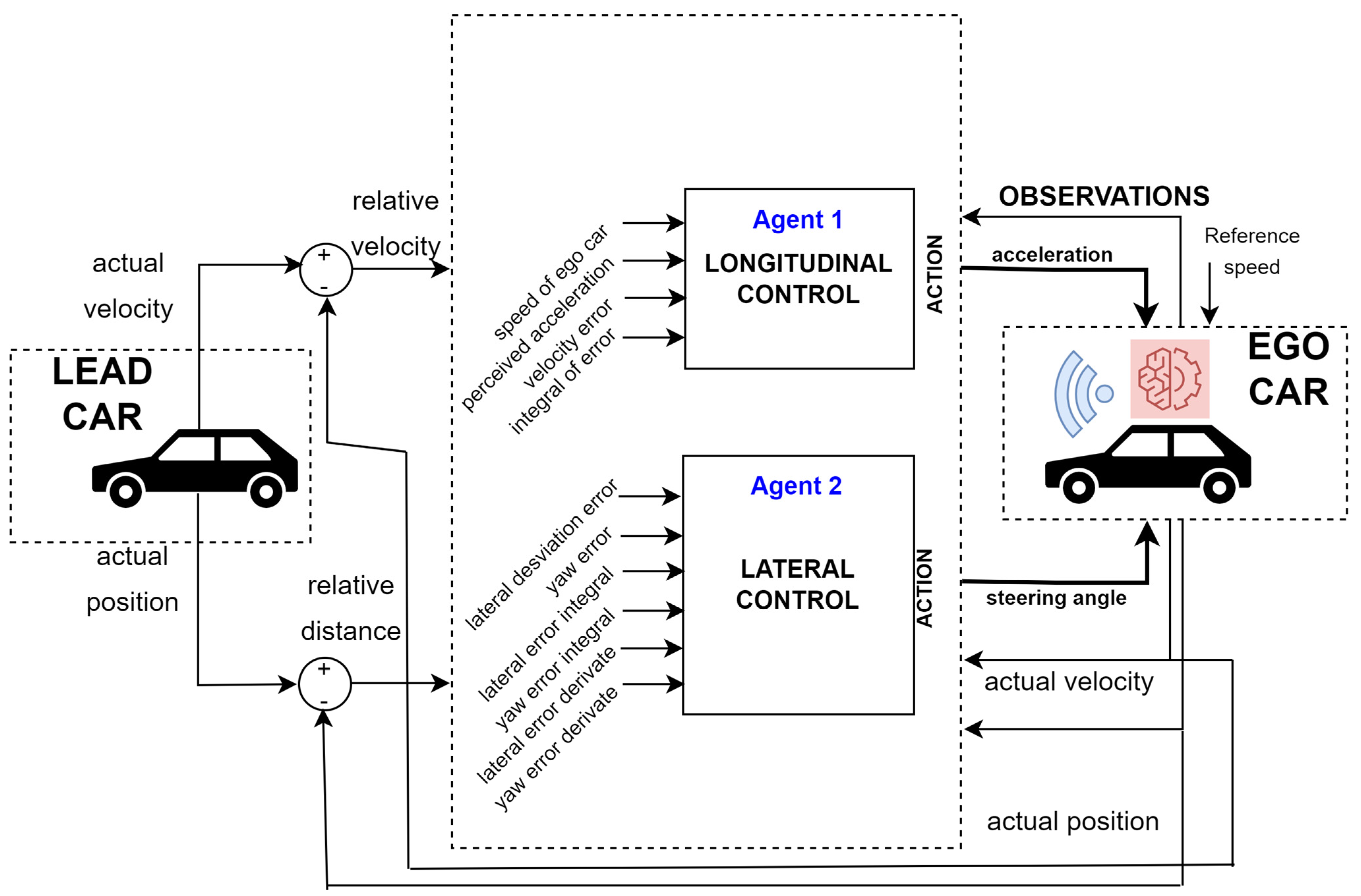
Figure 1 shows the diagram of the longitudinal and lateral vehicle control system proposed in this article.
The vehicle adjusts its speed to that of the vehicle in front of it or to a slower speed, ensuring comfortable acceleration. Using inertial data from the vehicle, the driver’s acceleration due to the road is evaluated, helping to complement other driver assistance systems and supporting potential autonomous driving applications for greater safety and comfort.
4. Methodology
4.1. A Vehicle System to Assist in the Driving Task
Sustainable driving is an approach designed to conserve energy, reduce air and noise pollution, decrease carbon dioxide emissions, and support global efforts to combat climate change. Vehicle energy consumption and emissions are influenced by a range of physical factors, including road traffic conditions, vehicle characteristics, road conditions, and road geometry. In addition to these physical factors, driving style plays a crucial role in energy consumption, even when other factors remain constant. Simple driving techniques based on engine characteristics can significantly reduce energy consumption. In contrast, aggressive driving—characterised by speeding, rapid acceleration, and harsh braking—leads to substantial energy waste. Avoiding unnecessary acceleration, practicing smooth braking, and maintaining an optimal cruising speed can improve fuel efficiency.
Current driving assistance systems typically offer general advice without considering specific contexts, and this negatively impacts drivers’ capacity to optimise their behaviour. The dynamics of traffic flow influence vehicle operations, necessitating effective systems that can predict and adapt to future traffic conditions and variations.
The purpose of this paper was to explore the function of a driving assistance system and its role in providing support to the driver. This study proposes a driving assistance system that attempts to minimise driving effort and energy consumption based on the perception of road geometry, taking into account the influence of the road itself on the vehicle.
4.2. Deep Reinforcement Learning Vehicle Control System
The deep reinforcement learning (DRL) vehicle control system described in this study considers the influence of road curvature (
Figure 1 and
Figure 2). This effect is obtained from vehicle dynamics, which uses measurements of longitudinal and lateral acceleration, yaw, and steering angle to quantify the forces acting on the vehicle.
The driving behaviour when approaching a curve is characterised by the following consideration: if the vehicle’s turning speed is too high, it leads to increased lateral acceleration, thereby compromising manoeuvrability. The perceived lateral acceleration, which represents the driver’s sensation during the drive, becomes more noticeable under such conditions. As a result, the road curvature effect is indirectly captured through the vehicle’s dynamics by measuring the longitudinal and lateral accelerations and yaw rate.
Moreover, when turning at high speeds, understeering phenomena can arise. In this case, the steering angle must be carefully controlled within a specific range to avoid causing the rear of the vehicle to skid, which would result in oversteering. Conversely, understeering occurs if the actual turning radius is smaller than the theoretical turning radius, which should be determined by the position of the front wheels.
By analysing the vehicle dynamics, as outlined in
Table 1, we can derive the perceived acceleration experienced by the driver and, consequently, evaluate the road curvature effect during each curve transition.
Deep reinforcement learning (DRL) was used for the autonomous vehicle control system. The simulation environment included a 3-degree-of-freedom (DOF) model for the ego vehicle and a simplified longitudinal model for the lead vehicle. The aim of the training was to achieve the ego car driving at a reference speed while maintaining a safe distance to the leading vehicle by controlling the longitudinal acceleration without exceeding the speed of the leading vehicle by as much as possible. The longitudinal controller took into account the interaction of the ego vehicle with the vehicles ahead, while the lateral controller only took into account the elements that affected the lateral movement of the ego vehicle.
Table 2 shows the vehicle data parameters used.
The interaction between the ego vehicle and the lead vehicle is defined as follows: when the relative distance between the two vehicles is less than a predefined safety threshold, the ego vehicle reduces its speed to the minimum of either the lead vehicle’s speed or the reference speed (
vref), ensuring the safety distance is maintained. If the relative distance exceeded the safety threshold, the ego vehicle accelerated to follow the reference speed. To improve realism, the system also incorporated variable road curvature.
Figure 2 provides an illustration of the proposed system and its environment.
In this paper, deep learning techniques were used to train driving rules using the Deep Deterministic Policy Gradient (DDPG) and Deep Q-Network (DQN) agents. The learned policies were then used to control the vehicle’s longitudinal acceleration and steering angle in a dynamic environment. The training consisted of two phases. The first phase introduced the influence of road curvature through perceived acceleration and the understeering phenomena. In the second phase, the agents were re-trained to include the rollover phenomenon.
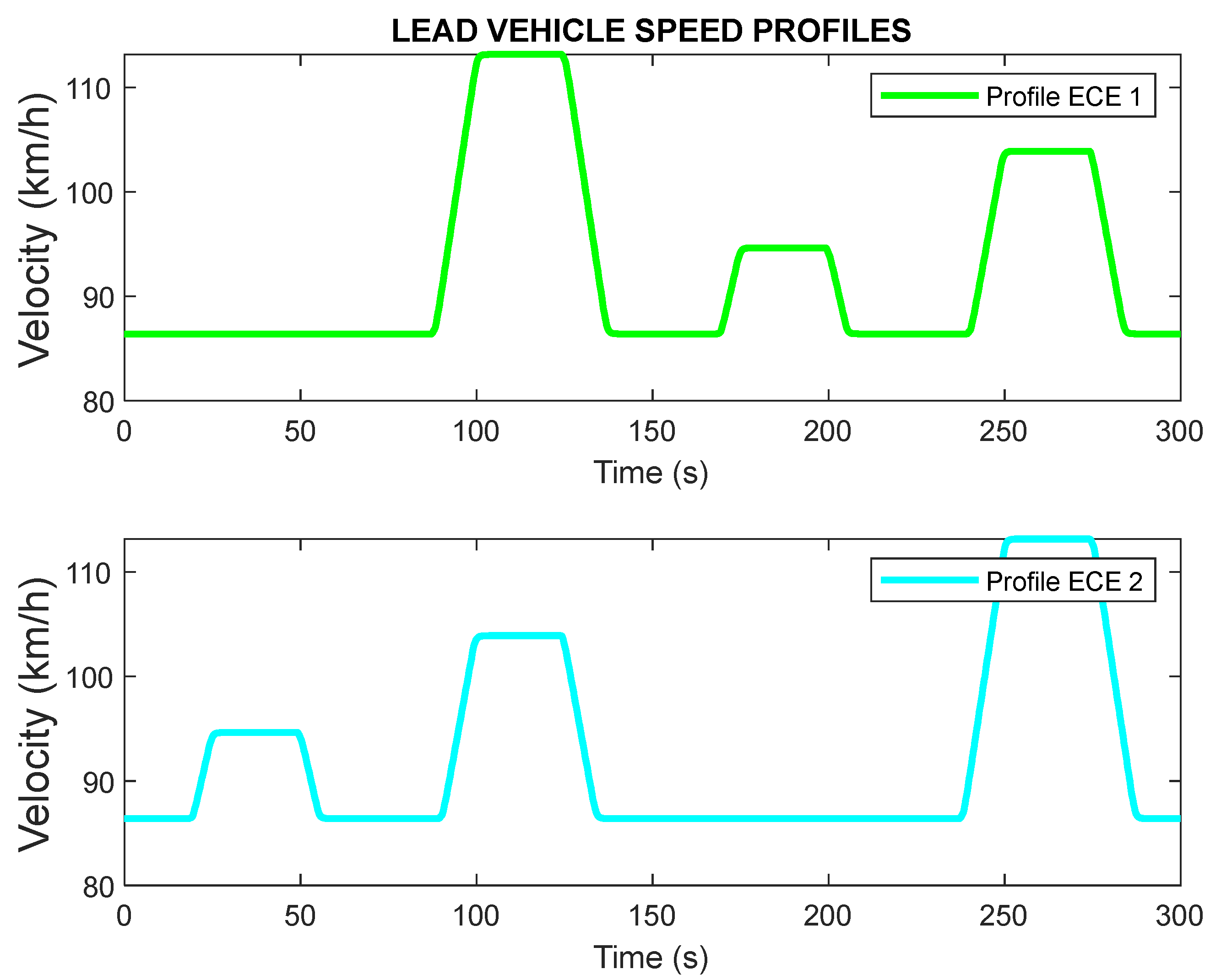
For training purposes, a sinusoidal signal was used to generate the speed profile of the lead vehicle in order to achieve robustness to changes in acceleration and speed of the preceding vehicle on the ego vehicle, and it was used as the reference vehicle speed, with each training trial lasting 60 s. Training consisted of two phases: first, the model was trained without the rollover coefficient (RC) reward; then, the RC reward was added, and the resulting agents were retrained. Experiments lasted between 2.5 and 4 h. The tests were carried out in a simulated environment for 300 s using the ECE profiles of the lead vehicle to ensure realism.
Table 3 shows training parameters.
The system was tested with initial conditions of 65 km/h for the test vehicle and a parameterised vehicle distance of 10 m. The lateral deviation parameters were also set to 0.2 m and the yaw angle to −0.1 rad. The lateral deviation parameters were also set to 0.2 m and the yaw angle to −0.1 rad. A curvature, including a generated curve with a radius of 100 m, was introduced to create a sudden and abrupt change in the road to achieve realism and to obtain the response of the vehicle control to a sudden change. For the driving simulation, the ego car followed the preceding vehicle for 300 s.
The ECE cycle, often referred to as the Urban Driving Cycle (UDC), is a standard driving cycle used to simulate typical urban or interurban driving conditions. This cycle is characterised by low vehicle speeds, minimal engine load, and low exhaust temperatures. It serves as the reference cycle for simulating road tests for light commercial vehicles [
36]. The standard ECE driving cycle includes various phases, such as acceleration, constant speed, and deceleration, which are designed to represent typical driving behaviour. In this study, ECE profiles were used to assess the effectiveness of the proposed vehicle control system and how the preceding vehicle performed ECE profiles, as shown in
Figure 3.
4.3. DDPG-Based Vehicle Longitudinal Control
The ego vehicle’s longitudinal control was provided by a Deep Deterministic Policy Gradient (DDPG) agent. In this approach, the DDPG calculates the reward for the agent’s observations and actions using a critical value function representation. Based on this, the agent chooses actions using a representation of the actor’s policy. The observations provided by the environment included the following longitudinal measurements:
Vehicle’s longitudinal speed (vl);
Speed error (ev);
Integral of the speed error;
Lateral perceived acceleration (ap);
Longitudinal jerk (Jk).
The reward function for the Deep Deterministic Policy Gradient (DDPG) agent is designed to incorporate several factors to encourage safe and efficient driving behaviour. Specifically, the reward at time step t, denoted as r(t), depends on the error speed ev (which is the difference between the lead vehicle’s speed and the ego vehicle’s speed), the previous time step’s longitudinal acceleration input a(t − 1), the previous time step’s lateral perceived acceleration ap(t − 1), and the longitudinal jerk jk(t − 1), which measures sudden changes in longitudinal acceleration. Constants A, B, C, and D are used to weigh these factors based on their relative importance to the system’s objectives. The action signal in the longitudinal control system consists of continuous acceleration values, ranging between −3 m/s2 and 2 m/s2.
The reward function can be written as follows:
where:
ev(t) is the speed error between the lead and ego vehicle at time step t;
a(t − 1) is the longitudinal acceleration at the previous time step;
ap(t − 1) is the lateral perceived acceleration at the previous time step;
jk(t − 1) is the longitudinal jerk at the previous time step, which helps evaluate sudden or erratic changes in acceleration;
A, B, C, and D are constants that are tuned to balance the importance of each factor in the reward. A = 1/100, and B = 1/10. C and D are constants that are dependent on the following:
The constants C and D depend on various system parameters, such as the desired comfort and safety levels, the vehicle’s dynamic characteristics, and the environment’s driving conditions (road curvature). These constants play a crucial role in guiding the agent’s learning process by emphasising the importance of minimising speed errors and smooth acceleration while maintaining stability and comfort during driving.
This setup allows for the DDPG agent to minimise speed error, maintain smooth acceleration as far as possible, and ensure safe and efficient driving, considering road curvature. The second column of
Table 3 shows the configured hyperparameters of the DDPG agent for longitudinal control.
4.4. DQN-Based Vehicle Lateral Control
The reward function for the Deep Q-Network (DQN) agent in the lateral control system is designed to optimise the steering behaviour of the vehicle. The observations include the following:
Lateral deviation (e1): this is the difference between the vehicle’s current position and the desired path.
Relative yaw angle (e2): this is the angle between the centreline of the vehicle and the tangent to the desired path.
Derivatives and integrals of e1 and e2: these derivatives account for changes in the lateral deviation and yaw angle, helping to assess the dynamic behaviour of the vehicle.
Lateral deviation (e1), the relative yaw angle (e2), their derivatives, and their integrals provide insight into the lateral movement of the vehicle, which the DQN agent uses to adjust the steering angle to minimise lateral deviation and maintain proper vehicle orientation. The action signal includes continuous steering angle values between −0.5 and 0.5 radians.
The reward r(t) at each time step t is calculated based on the following factors:
where:
e1 is the lateral deviation at time step t, the difference between the vehicle’s current position and the desired path.
s(t − 1) is the steering input from the previous time step,
A, B, C, D, and E are constants that are tuned to balance the importance of each factor in the reward. A = 1/10, and B = 1/2. C, D, and E are constants which depend on the following:
The constants C, D, and E are tuned to balance the relative importance of minimising lateral deviation and yaw angle, their rates of change, and their accumulated effects over time. By adjusting these constants, the DQN agent learns to select steering actions that minimise lateral errors and maintain stable vehicle control while driving.
Using the Ackerman approach, a US value close 1 stabilises yaw motion by considering current and geometric yaw rates. This minimises understeering and oversteering, reducing lateral deviation.
Table 3, third column, shows the DQN agent’s hyperparameters for lateral control.
In this approach, the system focused on minimising understeering (US) and oversteering by keeping the yaw motion stable. The Ackermann approach ensured that the yaw rate, which represented the vehicle’s rotational movement, remained within acceptable limits, promoting stable handling. If the US value approached 1, it indicated that the system was achieving a balance between the actual yaw rate and the geometric yaw rate, implying stable vehicle dynamics. By training the agent to minimise understeering and oversteering, the system also aimed to maintain minimal lateral deviation, ensuring the vehicle stayed on its desired path. Moreover, the rollover phenomenon (RC) was considered to be the avoidance or prevention of rollover of the vehicle, keeping the value of the coefficient around a small value close to zero.
The Deep Q-Network (DQN) agent is designed to optimise lateral vehicle control by adjusting the steering angle based on real-time feedback. It minimises lateral deviation and mitigates understeering or oversteering by stabilising the vehicle within an optimal yaw rate range. The agent’s learning process is guided by specific hyperparameters (
Table 3), including the learning rate, discount factor, and exploration–exploitation balance, which influence its performance in achieving stable and efficient vehicle control.
5. Results and Discussion
Road conditions, and in particular road geometry, have a significant impact on the experience of road users in terms of both comfort and safety. Well-designed road geometry has a direct impact on how safe and comfortable people feel while driving. Simulation tests evaluate the speed achieved by the vehicle control system, considering various road characteristics such as variable road curvature, which helps in modelling real road conditions. The system simulates how the vehicle interacts with these road characteristics to provide a more accurate representation of driving behaviour.
The training time for the Deep Deterministic Policy Gradient (DDPG) and Deep Q-Network (DQN) agents is considerable, with each simulation taking over an hour to complete. This high computational demand is primarily due to the complexity of the environment and the need for repeated simulations to train the agents effectively. The experiments were conducted on a computer with an Intel Core i7 1.2 GHz processor and 8 GB of RAM.
The results of the simulations are presented through various figures, highlighting key vehicle dynamics and control metrics.
Figure 3, Figures 5 and 7 show the longitudinal behaviour of the vehicle, while Figures 4, 6 and 8 focus on lateral control aspects.
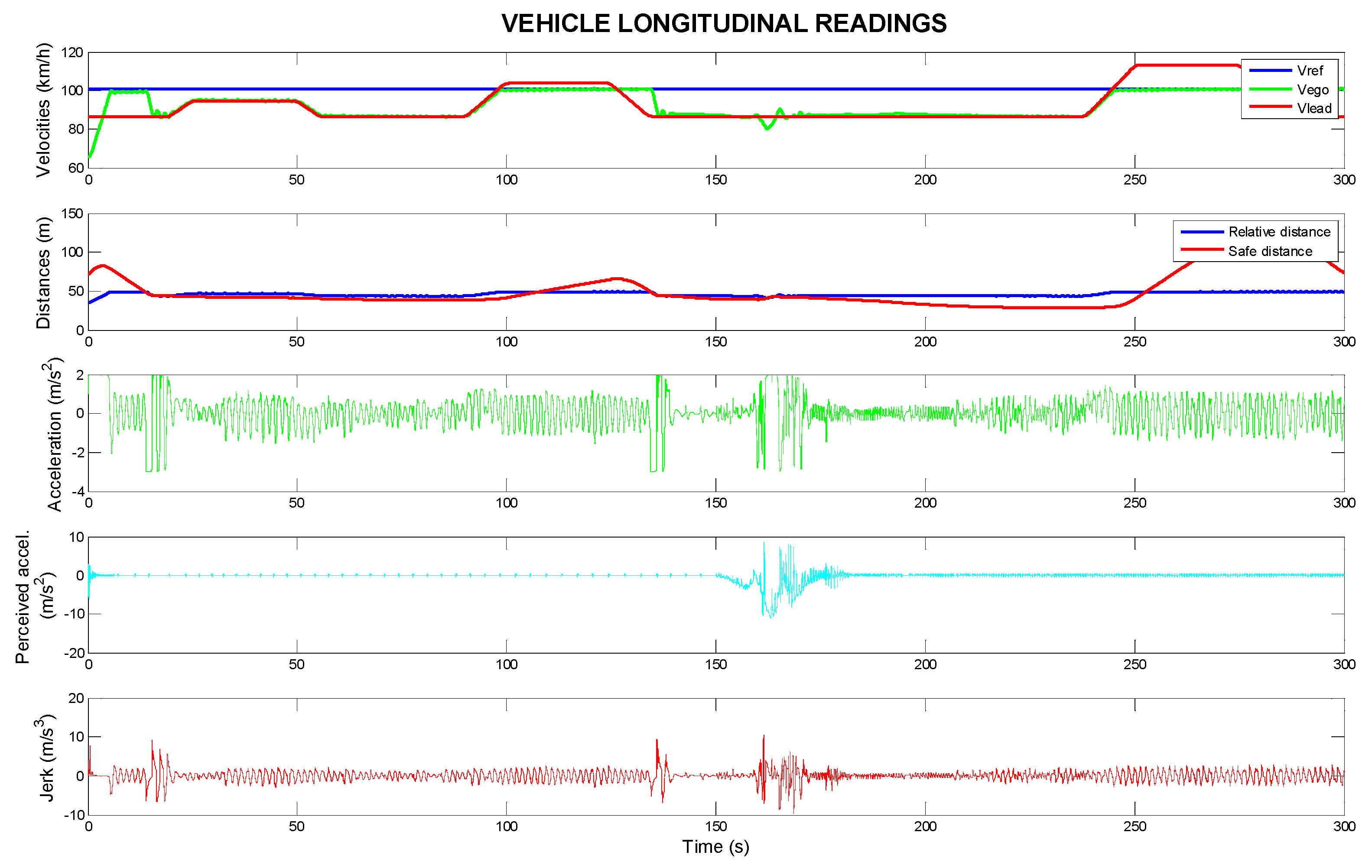
In each figure, information is shown as follows:
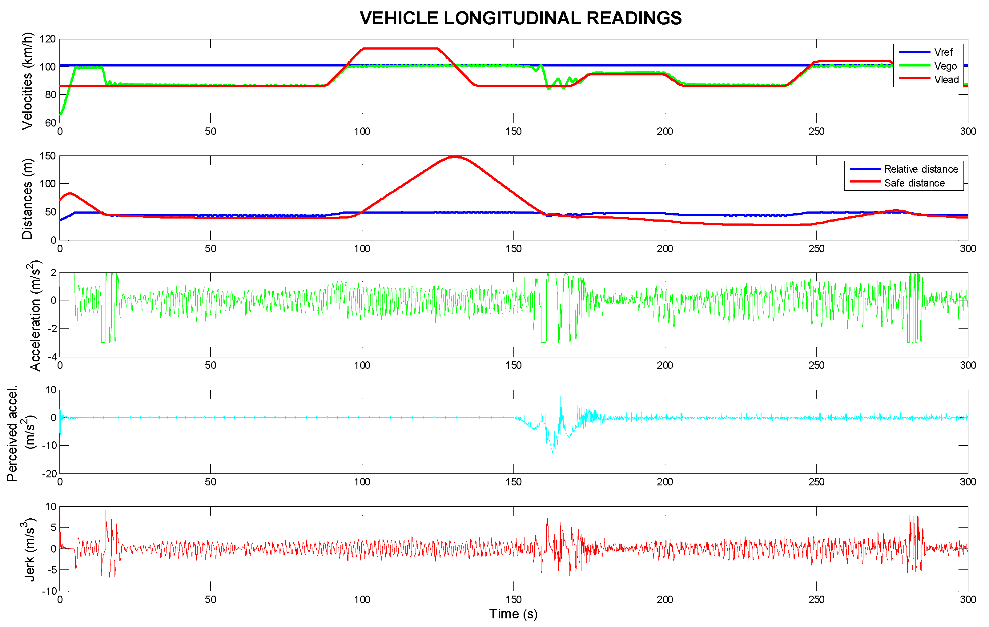
The upper graph displays the speeds of the ego vehicle (in red), the lead vehicle (in orange), and the reference speed (vref) of the ego vehicle (in blue), all in km/h. This gives an overview of how the ego vehicle adjusts its speed relative to the vehicle ahead and its reference speed.
The second graph displays the safe and relative distance between the ego vehicle and the lead vehicle in meters. Maintaining a safe distance is crucial for ensuring both comfort and safety, especially in dynamic traffic situations.
The third graph represents the instantaneous longitudinal acceleration (in m/s2), indicating how the vehicle’s speed is being adjusted at any given moment.
The fourth graph displays the lateral perceived acceleration (in m/s2), which is the driver’s feeling of acceleration due to road geometry, influencing comfort and safety in turns.
The bottom graph shows the vehicle jerk (in m/s3), which measures the rate of change in acceleration over time. High jerk values are often associated with abrupt and uncomfortable driving manoeuvres, which can detract from the comfort of passengers.
By evaluating these figures, it is possible to assess the performance of the vehicle control system under various driving conditions and its ability to maintain safe, smooth, and comfortable driving behaviours in both longitudinal and lateral control tasks.
Figure 4 shows the trajectory tracking system’s data for the lead car, using the ECE 1 speed profile, with a focus on the ego vehicle’s longitudinal travel. The speed of the ego vehicle (in km/h), the reference speed (
vref), and the speed of the lead vehicle are displayed. The ego vehicle accelerates to match the reference speed and changes its speed to match the lead vehicle if its initial speed is lower than the reference speed. This ensures that the following vehicle maintains a safe following distance and adapts to the speed of the lead vehicle. The relative distance (in meters) is between the ego vehicle and the lead vehicle. The distance increases when the lead vehicle is travelling faster than the ego vehicle. It reflects the system’s ability to maintain a safe distance and adjust the speed accordingly. Longitudinal acceleration (in m/s
2) is shown, which changes based on the road conditions and the speed of the lead vehicle. When the curvature of the road increases (the radius of curvature decreases), the ego vehicle adjusts its speed by modifying its longitudinal acceleration. These changes are not abrupt and occur gradually, ensuring smooth driving behaviour. For passenger comfort, this acceleration should be less than 2 m/s
2 [
37]. Perceived lateral acceleration (in m/s
2) is shown. It stays within the comfortable increments range of −0.5 to 0.5 m/s
2, ensuring a pleasant driving experience for the passengers. This range indicates that the system is successfully managing lateral forces and providing stability during turns. For passenger comfort, this acceleration should be less than 1.5 m/s
2 [
37]. The jerk (in m/s
3) is close to zero except in areas where the road curvature changes. In these areas, typically where the radius of curvature is around 100 m, the jerk increases briefly, indicating a smooth transition in acceleration as the system adapts to road geometry.
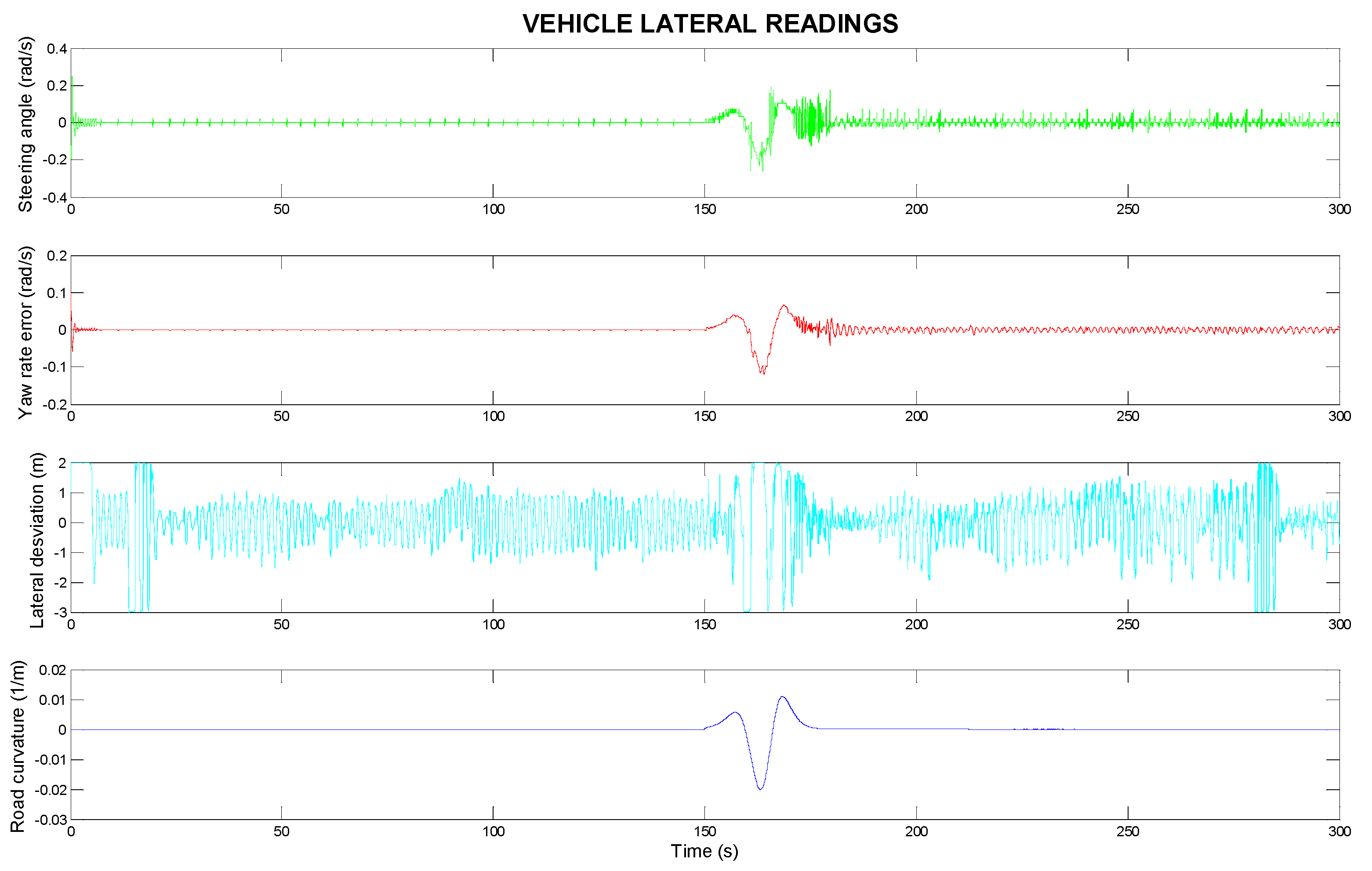
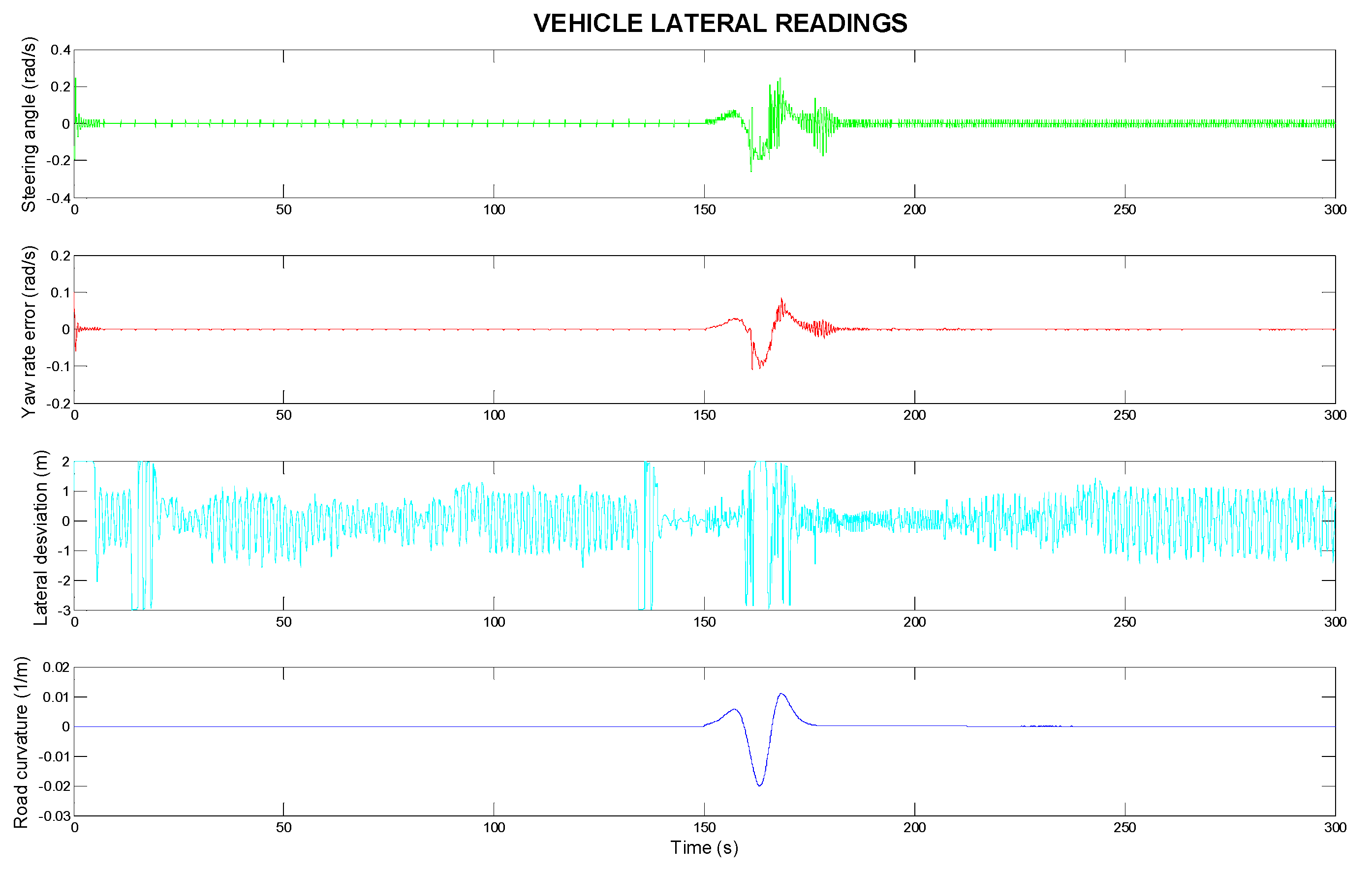
Figure 5 focuses on the lateral control aspect of the vehicle control system, with the ECE 1 speed profile demonstrating the vehicle’s lateral behaviour. The steering angle (in rad/s) applied to the ego vehicle is shown. It adjusts to keep the vehicle centred on the road, ensuring smooth lane-keeping behaviour. The yaw rate error (in rad/s) is displayed. This value is either zero or close to zero, indicating that the vehicle is maintaining a stable yaw rate and is accurately following the intended trajectory. The lateral deviation (in meters) of the ego vehicle is shown. It reflects how well the vehicle stays centred in the lane. Ideally, the lateral deviation remains minimal, demonstrating effective lane-keeping. The road curvature (in m
−1) is shown, indicating how the curvature of the road influences the vehicle’s steering angle and lateral control. The vehicle responds to changes in road curvature, especially in areas with smaller radii of curvature, to maintain stability and stay centred in the lane. For smooth and controlled driving, the recommended steering angular velocity is 0.4 rad/s. This range allows for gradual lane changes and normal cornering without excessive lateral acceleration.
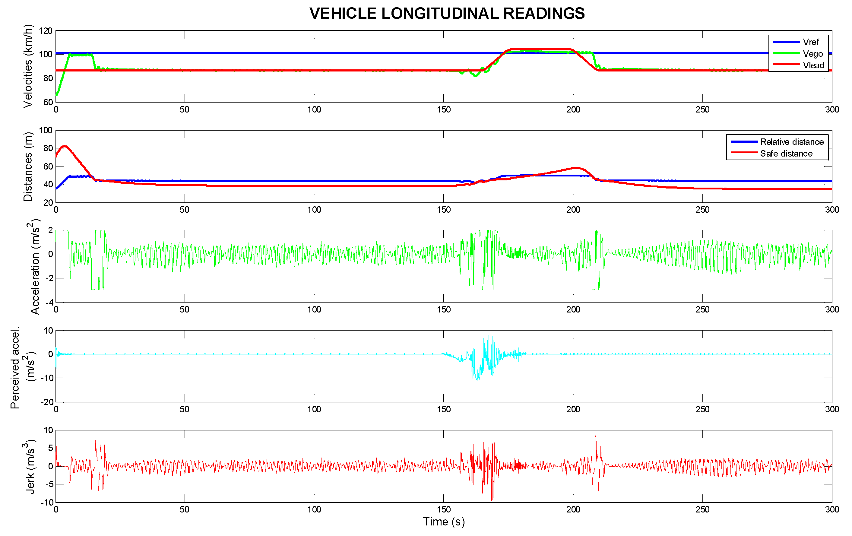
Figure 6 illustrates the longitudinal control of the vehicle using the ECE 2 speed profile. It shows the speed of the ego vehicle, reference speed (
vref), and lead vehicle speed. Initially, the ego vehicle accelerates to match the reference speed and then adjusts to the lead vehicle’s speed. The system modifies the speed based on the relative distance between the vehicles. Longitudinal acceleration varies with road conditions and lead vehicle speed, adjusting as the road curvature increases. Perceived lateral acceleration remains comfortable within −0.5 to 0.5 m/s
2. Jerk increases briefly in areas with changing road curvature, indicating smooth transitions in acceleration for passenger comfort, similar to
Figure 4.
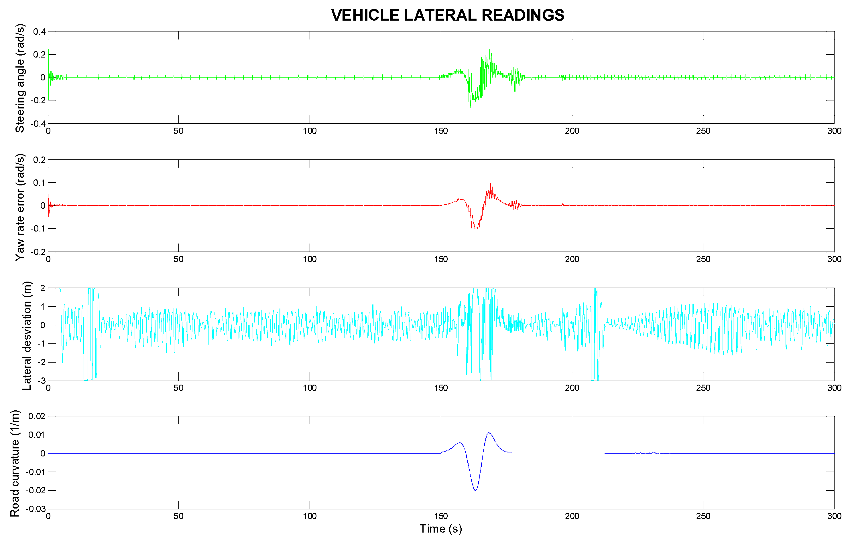
Figure 7 illustrates the lateral control of the vehicle with the ECE 2 speed profile. The steering angle (in rad/s) adjusts to keep the vehicle centred on the road for smooth lane-keeping. The yaw rate error (in rad/s) is near zero, showing stable yaw rate and accurate trajectory. The lateral deviation (in meters) indicates how well the vehicle stays in its lane; ideally, it remains minimal for effective lane-keeping. The road curvature (in m
−1) influences the steering angle and lateral control, with the vehicle responding to changes, especially in areas with smaller radii of curvature. The suggested steering angular velocity remains constant.
Figure 8 illustrates the longitudinal control of the vehicle using the ECE 3 speed profile. It shows the speed of the self-car, the reference speed, and the speed of the lead car. Initially, the ego vehicle accelerates to the reference speed and then to the speed of the lead vehicle. The system modifies the speed according to the relative distance between the vehicles. Longitudinal acceleration varies according to road conditions and the speed of the lead vehicle, adjusting as the curvature of the road increases. Perceived lateral acceleration remains comfortably between −0.5 and 0.5 m/s
2. Jerk increases briefly in areas of changing road curvature, indicating smooth transitions in acceleration for passenger comfort, similar to
Figure 4 and
Figure 6.
Figure 9 illustrates the lateral control of the vehicle with the ECE 3 speed profile. The steering angle (in rad/s) is adjusted to keep the vehicle centred on the road and to maintain the lane smoothly. The yaw rate error (in rad/s) is close to zero, indicating a stable yaw rate and accurate trajectory. Lateral deviation (in metres) indicates how well the vehicle maintains its lane; ideally, it should be minimal for effective lane keeping. Road curvature (in m
−1) affects steering angle and lateral control, and the car reacts to changes, especially in areas with smaller radii of curvature. The suggested steering angle remains constant. The ECE 3 speed profile has fewer changes in the speed of the vehicle in front of it, and the changes are less abrupt and mostly coincide in the area where the curvature changes.
These results illustrate the ability of the vehicle control system to adapt to both the longitudinal and lateral dynamics of the vehicle, ensuring safe and comfortable driving while taking into account road geometry, vehicle speed, and curvature. The system efficiently manages the vehicle’s acceleration, steering, and jerk, contributing to smooth and safe driving behaviour. The ego vehicle successfully follows the lead vehicle, maintaining a safe distance and adjusting its speed to that of the lead vehicle if necessary. If the lead vehicle is travelling slower than the reference speed (vref), the following vehicle will slow down to match it. This adjustment ensures that the ego vehicle maintains a safe following distance and performs efficiently in a variety of traffic conditions. The acceleration and jerk of the self-vehicle show remarkable changes, particularly in areas where the radius of the curve changes abruptly. These changes become more pronounced as the road geometry changes, demonstrating the system’s ability to adapt to different road conditions. In particular, the ego adjusts its longitudinal acceleration to handle the abrupt curve while minimising the jerk to ensure comfort.
The results shown in
Figure 6,
Figure 7,
Figure 8 and
Figure 9 illustrate the ability of the autonomous system to manage both longitudinal and lateral vehicle dynamics, thereby optimising the driving experience. By continuously analysing the behaviour of the lead vehicle and the geometric characteristics of the road, the system dynamically adjusts acceleration, braking and steering to ensure smooth motion and operational efficiency. The vehicle control strategy facilitates smooth acceleration and deceleration while maintaining stringent safety margins and robust lane-keeping performance. The system also demonstrates adaptability to varying road curvature and external driving conditions, enhancing overall vehicle stability and reliability. These results underline the effectiveness of advanced autonomous control methods in achieving a balance between safety, comfort, and operational efficiency in intelligent transport systems.
In order to assess the effectiveness of the proposed vehicle control system, a comparative analysis is carried out with existing driver assistance technologies, namely adaptive cruise control (ACC). ACC is widely used in modern vehicles to maintain a safe distance from other vehicles by autonomously adjusting the vehicle’s speed. However, ACC systems have limitations when dealing with complex road geometries and dynamic driving conditions. The authors of [
19] propose the use of deep reinforcement learning (DRL) to ensure safe and comfortable driving. This method results in jerk levels of about 10 m/s
3 during acceleration and 16–18 m/s
3 during abrupt deceleration in traffic. Notably, this model does not take road curvature into account. In contrast, our investigation found rare jerk peaks that were not caused by rapid deceleration of the lead vehicle or abrupt changes in road curvature. During acceleration, the highest jerk value is 5 m/s
3, with peaks of up to 10 m/s
3 during sudden decelerations. The human-like perception approach used in our model can minimise both the intensity and the duration (between 4 and 5 s) of these jerk peaks when the lead vehicle’s speed reduces sharply, compared to the results in [
19].
This demonstrates that incorporating human-like perception can reduce the discomfort associated with over-acceleration caused by road design and high speeds in bends by reducing the centripetal force experienced by the driver. Nevertheless, there remains a rolling motion speed where acceleration does not occur, thus avoiding unnecessary jerking or cornering, although the sensation of centripetal force remains unavoidable. To achieve a more comfortable driving experience, it is essential to mitigate this phenomenon, quantified in terms of perceived acceleration, while also minimising understeering and oversteering that may occur when driving at excessive or inappropriate speeds. Such conditions can cause the car to leave the road and result in an accident. This distinction distinguishes our model from others in the literature.
In conclusion, our study’s deep reinforcement learning-based vehicle control system can provide acceleration values for longitudinal vehicle motion as well as steering angle adjustments to keep the vehicle in place on the road. The apparent lateral acceleration is small, and the longitudinal jerk is lower than the thresholds defined for passenger comfort [
37] during the tracking of the lead vehicle, without considering abrupt changes in the speed of the lead car and the curvature section, which considers a very small curve radius of 100 m. The model computes the acceleration induced by the road and the perceived acceleration experienced by the driver, considering understeering phenomena that often occur during cornering or when the vehicle is travelling at high speeds [
38].
This system can contribute to a safer and more comfortable driving experience by incorporating measurements into existing vehicles. It also has the potential to help semi-autonomous or fully autonomous vehicles operate efficiently by taking into account the driver’s perception of road geometry while reducing the risk of skidding and off-road accidents.
6. Conclusions
The study presents a novel intelligent vehicle control system that includes the effect of road geometry and dynamic vehicle behaviour. At the core of the system is deep reinforcement learning (DRL), which has been recognised as a powerful tool for solving complex control problems in autonomous driving scenarios. This approach uses vehicle sensor data, including acceleration and steering inputs, to build a more accurate model of driver behaviour and vehicle dynamics. The model calculates the acceleration induced by the road and the perceived acceleration experienced by the driver, considering understeering, oversteering, and rollover.
Deep reinforcement learning techniques, specifically Deep Deterministic Policy Gradient (DDPG) and Deep Q-Network (DQN) agents, are used to train the system based on these inputs. The trained agents generate precise control commands for the vehicle’s longitudinal and lateral systems, controlling acceleration and steering. This method enables the vehicle to follow paths more accurately, considering road curvature that impacts driver performance and safety. The study shows that the DRL-based system, considering road geometry, significantly outperforms the ACC system by reducing abrupt acceleration changes.
This study finds that the DRL-based vehicle control system offers valuable insights into driver behaviour modelling in relation to road geometry. Using acceleration, gyroscopic data, and steering data from sensors in modern vehicles, the system demonstrates its effectiveness. By incorporating the driver’s subjective perception of road curvature, the model aims to provide a smoother and safer driving experience by minimising the discomfort associated with abrupt changes in acceleration or steering.
In addition, the study highlights the potential for expanding the scope of driver assistance systems to include a wider range of factors that influence driving behaviour. Future research could explore the integration of additional intelligent sensors, such as those monitoring drowsiness, distraction, and fatigue, which are critical to understanding driver impairment. In addition, external factors such as weather conditions and wheel–road interactions could further enhance the system’s ability to adapt to real-world conditions, making it a more robust and reliable tool for improving safety and comfort.
Further developments in this area should focus on improving the robustness of the DRL-based lane-keeping system by incorporating real-time data from more advanced sensors, such as those monitoring driver alertness and environmental conditions. The potential integration of systems to measure factors such as drowsiness and fatigue would help the model adapt to a wider range of driving conditions, improving the safety of both autonomous and human-assisted driving. In addition, studying the dynamics of wheel–road interaction, which can have a significant impact on vehicle control, could improve the model’s sensitivity to changes in road conditions, such as wet or icy surfaces.
In future, research could also focus on refining the system’s ability to handle extreme driving situations, such as sharp turns, sudden lane changes, and emergency manoeuvres. The integration of weather data, including rain, fog, and snow, could further improve the system’s adaptability. Understanding how these factors interact with the vehicle’s dynamic systems would provide a more comprehensive approach to vehicle control behaviour, ensuring safer road use in all conditions.


